CN101532641A - Light source device - Google Patents
Light source deviceDownload PDFInfo
- Publication number
- CN101532641A CN101532641ACN200810085351ACN200810085351ACN101532641ACN 101532641 ACN101532641 ACN 101532641ACN 200810085351 ACN200810085351 ACN 200810085351ACN 200810085351 ACN200810085351 ACN 200810085351ACN 101532641 ACN101532641 ACN 101532641A
- Authority
- CN
- China
- Prior art keywords
- light
- light source
- guide column
- source device
- light guide
- Prior art date
- Legal status (The legal status is an assumption and is not a legal conclusion. Google has not performed a legal analysis and makes no representation as to the accuracy of the status listed.)
- Pending
Links
- 230000003287optical effectEffects0.000claimsdescription71
- 238000009792diffusion processMethods0.000claimsdescription10
- 230000000007visual effectEffects0.000description6
- 241000699670Mus sp.Species0.000description1
- 239000012141concentrateSubstances0.000description1
- 239000006185dispersionSubstances0.000description1
- 230000000694effectsEffects0.000description1
- 238000005516engineering processMethods0.000description1
- 230000007613environmental effectEffects0.000description1
- 230000004313glareEffects0.000description1
- 238000001746injection mouldingMethods0.000description1
- 238000000034methodMethods0.000description1
- 238000012986modificationMethods0.000description1
- 230000004048modificationEffects0.000description1
- 230000000644propagated effectEffects0.000description1
- 230000011514reflexEffects0.000description1
- 239000004065semiconductorSubstances0.000description1
Images


Landscapes
- Non-Portable Lighting Devices Or Systems Thereof (AREA)
Abstract
Description
Translated fromChinese技术领域technical field
本发明涉及一种光源装置,且特别是涉及一种采用导光柱的光源装置。The invention relates to a light source device, and in particular to a light source device using a light guide rod.
背景技术Background technique
随着半导体技术的进步,发光二极管(light-emitting diode,LED)所能达到的功率越来越大,且所发出的光的强度越来越高,再加上发光二极管具有省电、使用寿命长、环保、启动快速、体积小...等多种优点,使得发光二极管的应用层面越来越广。此应用层面包括照明、交通号志、显示器、光学鼠标...等。With the advancement of semiconductor technology, the power that light-emitting diodes (LEDs) can achieve is getting larger and larger, and the intensity of the light emitted is getting higher and higher. Long life, environmental protection, fast start-up, small size, etc., make the application level of light-emitting diodes more and more extensive. This application level includes lighting, traffic signs, displays, optical mice...etc.
然而,由于发光二极管是点光源,随着发光强度越来越高,会使得强度极高的光都集中在一点上。当这样的点光源用于一般照明用途时,容易使得直视此点光源的人眼感到不舒服,亦即产生眩光,而使视觉舒适性下降。由于发光二极管的功率与亮度有越来越大的发展趋势,因此视觉舒适性的提升便越显得重要。However, since the light emitting diode is a point light source, as the luminous intensity becomes higher and higher, the light with extremely high intensity will be concentrated on one point. When such a point light source is used for general lighting purposes, it is easy to cause discomfort to human eyes looking directly at the point light source, that is, glare is generated, and the visual comfort is reduced. As the power and brightness of light-emitting diodes are increasingly developed, the improvement of visual comfort becomes more and more important.
一般而言,欲提升视觉舒适性可将扩散板或其他导光元件放置于发光二极管前,以产生亮度较为分散的光源。然而,在利用扩散板或导光元件来使亮度分散的同时,会使部分的光损失,而浪费了能源。因此,提升视觉舒适性的最佳方式不但要考虑到亮度的分散程度,也要考虑到光的利用率,而使得光损失尽可能减少,进而节约能源。Generally speaking, in order to improve visual comfort, a diffusion plate or other light guide elements can be placed in front of the LEDs to generate a light source with more dispersed brightness. However, when using a diffuser plate or a light guide element to disperse the brightness, part of the light will be lost, which wastes energy. Therefore, the best way to improve visual comfort should not only consider the degree of dispersion of brightness, but also the utilization rate of light, so as to minimize light loss and save energy.
发明内容Contents of the invention
本发明的目的在于提供一种光源装置,其能提供亮度较为分散的光源,且兼具较高的光利用率。The object of the present invention is to provide a light source device, which can provide a light source with relatively dispersed brightness and has a high light utilization rate.
本发明的一实施例提出一种光源装置,其包括至少一光源模块。光源模块包括一导光柱以及至少一第一发光元件。导光柱具有一第一端面、一第二端面、一出光面、一第一表面以及一第二表面。第二端面与第一端面相对。出光面连接于第一端面与第二端面之间。第一表面连接至第一端面,并与出光面相对,且相对出光面倾斜或平行。第一表面与第一端面在导光柱内的夹角大于或等于90度且小于180度。第二表面连接于第一表面与第二端面之间,并与出光面相对,且相对出光面倾斜。第一表面与第二表面在导光柱内的夹角大于0度且小于180度。第一发光元件配置于第一端面旁,并适于发出一第一光束。第一光束会由第一端面进入导光柱,并经由出光面传播至导光柱外。An embodiment of the invention provides a light source device, which includes at least one light source module. The light source module includes a light guide column and at least one first light emitting element. The light guide column has a first end surface, a second end surface, a light emitting surface, a first surface and a second surface. The second end surface is opposite to the first end surface. The light emitting surface is connected between the first end surface and the second end surface. The first surface is connected to the first end surface, is opposite to the light-emitting surface, and is inclined or parallel to the light-emitting surface. The included angle between the first surface and the first end surface in the light guide column is greater than or equal to 90 degrees and less than 180 degrees. The second surface is connected between the first surface and the second end surface, is opposite to the light-emitting surface, and is inclined relative to the light-emitting surface. The included angle between the first surface and the second surface in the light guide column is greater than 0 degree and less than 180 degree. The first light-emitting element is arranged beside the first end surface and is suitable for emitting a first light beam. The first light beam enters the light guide column from the first end surface, and propagates out of the light guide column through the light exit surface.
在本发明的一实施例中,导光柱更具有多个光学微结构,其位于第一端面,而第一光束会通过这些光学微结构。In an embodiment of the present invention, the light guide column further has a plurality of optical microstructures located on the first end surface, and the first light beam passes through these optical microstructures.
在本发明的一实施例中,导光柱更具有多个同心环状凹纹,其位于第一端面,而第一光束会通过这些同心环状凹纹。In an embodiment of the present invention, the light guide column further has a plurality of concentric ring-shaped grooves located on the first end surface, and the first light beam passes through these concentric ring-shaped grooves.
在本发明的一实施例中,导光柱更具有至少一容置凹面,其位于第一端面,以容置第一发光元件。In an embodiment of the present invention, the light guide column further has at least one accommodating concave surface located on the first end surface for accommodating the first light emitting element.
在本发明的一实施例中,导光柱更具有多个光学微结构,其位于容置凹面,而第一光束会通过这些光学微结构。In an embodiment of the present invention, the light guide column further has a plurality of optical microstructures located on the receiving concave surface, and the first light beam passes through these optical microstructures.
在本发明的一实施例中,导光柱更具有多个同轴环状凹纹,其位于容置凹面,而第一光束会通过这些同轴环状凹纹。In an embodiment of the present invention, the light guide column further has a plurality of coaxial annular grooves located on the receiving concave surface, and the first light beam passes through these coaxial annular grooves.
在本发明的一实施例中,导光柱更具有一第一图案化光学微结构,其位于第一表面及/或第二表面。In an embodiment of the present invention, the light guide column further has a first patterned optical microstructure located on the first surface and/or the second surface.
在本发明的一实施例中,光源模块更包括一第一扩散层,其配置于第一表面及/或第二表面上。In an embodiment of the present invention, the light source module further includes a first diffusion layer disposed on the first surface and/or the second surface.
在本发明的一实施例中,光源模块更包括一第一反射单元,其配置于第一表面上。In an embodiment of the present invention, the light source module further includes a first reflection unit disposed on the first surface.
在本发明的一实施例中,光源模块更包括一第二反射单元,其配置于第二表面上。In an embodiment of the present invention, the light source module further includes a second reflection unit disposed on the second surface.
在本发明的一实施例中,导光柱更更具有一第三表面,其连接于第一端面与出光面之间,并与第一表面相对。第三表面与第一端面在导光柱内的夹角大于90度且小于180度。In an embodiment of the present invention, the light guide column further has a third surface connected between the first end surface and the light-emitting surface, and opposite to the first surface. The included angle between the third surface and the first end surface in the light guide column is greater than 90 degrees and less than 180 degrees.
在本发明的一实施例中,导光柱可更具有一第二图案化光学微结构,其位于第三表面。In an embodiment of the present invention, the light guide column may further have a second patterned optical microstructure located on the third surface.
在本发明的一实施例中,光源模块更包括一第二扩散层,其配置于第三表面上。In an embodiment of the present invention, the light source module further includes a second diffusion layer disposed on the third surface.
在本发明的一实施例中,光源模块更包括一第三反射单元,其配置于第三表面上。In an embodiment of the present invention, the light source module further includes a third reflection unit disposed on the third surface.
在本发明的一实施例中,导光柱更具有一第四表面以及一第五表面。第四表面连接至第二表面,并与出光面相对,且相对出光面倾斜。第二表面与第四表面在导光柱内的夹角大于180度且小于360度。第五表面连接于第四表面与第二端面之间,并与出光面相对,且相对出光面倾斜或平行。第四表面与第五表面在导光柱内的夹角大于0度且小于180度。第五表面与第二端面在导光柱内的夹角大于或等于90度且小于180度。光源模块可更包括至少一第二发光元件,其配置于第二端面旁,并适于发出一第二光束。第二光束会由第二端面进入导光柱,并经由出光面传播至导光柱外。In an embodiment of the present invention, the light guide column further has a fourth surface and a fifth surface. The fourth surface is connected to the second surface, is opposite to the light-emitting surface, and is inclined relative to the light-emitting surface. The included angle between the second surface and the fourth surface in the light guide column is greater than 180 degrees and less than 360 degrees. The fifth surface is connected between the fourth surface and the second end surface, is opposite to the light-emitting surface, and is inclined or parallel to the light-emitting surface. The included angle between the fourth surface and the fifth surface in the light guide column is greater than 0 degree and less than 180 degree. An included angle between the fifth surface and the second end surface within the light guide column is greater than or equal to 90 degrees and less than 180 degrees. The light source module can further include at least one second light-emitting element, which is arranged beside the second end surface and is suitable for emitting a second light beam. The second light beam enters the light guide column from the second end surface, and propagates out of the light guide column through the light exit surface.
在本发明的一实施例中,光源模块更包括一第四反射单元,其配置于第二端面上。In an embodiment of the present invention, the light source module further includes a fourth reflection unit disposed on the second end surface.
在本发明的一实施例中,光源装置更包括一电连接器,其电连接至光源模块。In an embodiment of the present invention, the light source device further includes an electrical connector electrically connected to the light source module.
在本发明的一实施例中,上述至少一光源模块为多个光源模块,每一光源模块的导光柱沿着一第一方向延伸,且这些光源模块的这些导光柱沿着一与第一方向垂直的第二方向排列。In an embodiment of the present invention, the above-mentioned at least one light source module is a plurality of light source modules, the light guide columns of each light source module extend along a first direction, and the light guide columns of these light source modules extend along a first direction Aligned vertically in the second direction.
在本发明的一实施例中,上述至少一光源模块为多个光源模块,每一光源模块的导光柱沿着一第一方向延伸,且这些光源模块的这些导光柱沿着第一方向排列。In an embodiment of the present invention, the at least one light source module is a plurality of light source modules, the light guide columns of each light source module extend along a first direction, and the light guide columns of these light source modules are arranged along the first direction.
在本发明的一实施例中,第二端面的法向量与出光面的法向量的夹角大于或等于90度且小于180度。In an embodiment of the present invention, the included angle between the normal vector of the second end surface and the normal vector of the light-emitting surface is greater than or equal to 90 degrees and less than 180 degrees.
本发明的一实施例更提出一种光源装置,其包括至少一光源模块。光源模块包括一导光柱以及至少一第一发光元件。导光柱具有一第一端面、一第二端面、一环状表面、一出光面以及一第二表面。第二端面与第一端面相对。环状表面连接至第一端面。出光面连接于环状表面与第二端面之间,其中至少部分环状表面与出光面之间有段差。第二表面连接于环状表面与第二端面之间,并与出光面相对,其中至少部分环状表面与第二表面之间有段差。第一发光元件配置于第一端面旁,并适于发出一第一光束,其中第一光束会由第一端面进入导光柱,并经由出光面传播至导光柱外。An embodiment of the invention further provides a light source device, which includes at least one light source module. The light source module includes a light guide column and at least one first light emitting element. The light guide column has a first end surface, a second end surface, an annular surface, a light emitting surface and a second surface. The second end surface is opposite to the first end surface. The annular surface is connected to the first end surface. The light-emitting surface is connected between the annular surface and the second end surface, wherein at least part of the annular surface has a step difference from the light-emitting surface. The second surface is connected between the annular surface and the second end surface, and is opposite to the light-emitting surface, wherein at least part of the annular surface has a step difference from the second surface. The first light-emitting element is arranged beside the first end surface, and is suitable for emitting a first light beam, wherein the first light beam enters the light guide column from the first end surface, and propagates out of the light guide column through the light exit surface.
在本发明的一实施例中,导光柱具有一图案化光学微结构,位于第二表面上。导光柱是沿着一第一方向由第一端面往第二端面延伸,而图案化光学微结构可包括多个凹纹。每一凹纹沿着一与第一方向垂直的第二方向延伸,且这些凹纹沿着第一方向排列。In an embodiment of the present invention, the light guide column has a patterned optical microstructure on the second surface. The light guide column extends from the first end surface to the second end surface along a first direction, and the patterned optical microstructure may include a plurality of concave grooves. Each groove extends along a second direction perpendicular to the first direction, and the grooves are arranged along the first direction.
在本发明的一实施例中,第二端面包括多个子端面。每一子端面为曲面或平面,且相邻两子端面在导光柱内的夹角大于0度且小于180度。In an embodiment of the present invention, the second end surface includes a plurality of sub-end surfaces. Each sub-end surface is a curved surface or a plane, and the angle between two adjacent sub-end surfaces in the light guide column is greater than 0 degrees and less than 180 degrees.
在本发明一实施例的光源装置中,发光元件所发出的光会经过导光柱而转换为亮度较为分散的条状光源。此外,以较大角度偏离发光元件的光轴的光线能够被第一表面或环状表面反射,所以偏离光轴的光线仍能够被有效地利用,进而提升光源装置的光利用率。In the light source device according to an embodiment of the present invention, the light emitted by the light-emitting element is converted into a strip-shaped light source with relatively dispersed brightness through the light guide rod. In addition, the light that deviates from the optical axis of the light emitting element at a large angle can be reflected by the first surface or the annular surface, so the light that deviates from the optical axis can still be effectively used, thereby improving the light utilization efficiency of the light source device.
为让本发明的上述特征和优点能更明显易懂,下文特举多个实施例,并配合所附附图,作详细说明如下。In order to make the above-mentioned features and advantages of the present invention more comprehensible, a number of embodiments will be described in detail below together with the accompanying drawings.
附图说明Description of drawings
图1A为本发明第一实施例的光源装置的剖面示意图;1A is a schematic cross-sectional view of a light source device according to a first embodiment of the present invention;
图1B为图1A的光源装置的光源模块沿着I-I线的剖面示意图;1B is a schematic cross-sectional view of the light source module of the light source device of FIG. 1A along the line I-I;
图2为本发明第二实施例的光源装置的剖面示意图;2 is a schematic cross-sectional view of a light source device according to a second embodiment of the present invention;
图3A为本发明第三实施例的光源装置的光源模块的剖面示意图;3A is a schematic cross-sectional view of a light source module of a light source device according to a third embodiment of the present invention;
图3B绘示图3A中的导光柱以其第一端面朝前的侧视示意图;3B is a schematic side view of the light guide column in FIG. 3A with its first end facing forward;
图4A为本发明第四实施例的光源装置的光源模块的剖面示意图;4A is a schematic cross-sectional view of a light source module of a light source device according to a fourth embodiment of the present invention;
图4B绘示图4A中的导光柱以其第一端面朝前的侧视示意图;4B is a schematic side view of the light guide column in FIG. 4A with its first end facing forward;
图5为本发明第五实施例的光源装置的光源模块的剖面示意图;5 is a schematic cross-sectional view of a light source module of a light source device according to a fifth embodiment of the present invention;
图6A为本发明第六实施例的光源装置的光源模块的剖面示意图;6A is a schematic cross-sectional view of a light source module of a light source device according to a sixth embodiment of the present invention;
图6B绘示图6A中的导光柱以其第一端面朝前的侧视示意图;6B is a schematic side view of the light guide column in FIG. 6A with its first end facing forward;
图7为本发明第七实施例的光源装置的光源模块的剖面示意图;7 is a schematic cross-sectional view of a light source module of a light source device according to a seventh embodiment of the present invention;
图8为本发明第八实施例的光源装置的光源模块的剖面示意图;8 is a schematic cross-sectional view of a light source module of a light source device according to an eighth embodiment of the present invention;
图9为本发明第九实施例的光源装置的光源模块的剖面示意图;9 is a schematic cross-sectional view of a light source module of a light source device according to a ninth embodiment of the present invention;
图10为本发明第十实施例的光源装置的光源模块的剖面示意图;10 is a schematic cross-sectional view of a light source module of a light source device according to a tenth embodiment of the present invention;
图11为本发明第十一实施例的光源装置的光源模块的剖面示意图;11 is a schematic cross-sectional view of a light source module of a light source device according to an eleventh embodiment of the present invention;
图12为本发明第十二实施例的光源装置的光源模块的剖面示意图;12 is a schematic cross-sectional view of a light source module of a light source device according to a twelfth embodiment of the present invention;
图13为本发明第十三实施例的光源装置的剖面示意图;13 is a schematic cross-sectional view of a light source device according to a thirteenth embodiment of the present invention;
图14A为本发明第十四实施例的光源装置的光源模块的剖面示意图;14A is a schematic cross-sectional view of a light source module of a light source device according to a fourteenth embodiment of the present invention;
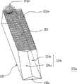
图14B为图14A中的导光柱的立体示意图;FIG. 14B is a schematic perspective view of the light guide column in FIG. 14A;
图15为本发明第十五实施例的光源装置的剖面示意图;15 is a schematic cross-sectional view of a light source device according to a fifteenth embodiment of the present invention;
图16为本发明第十六实施例的光源装置中的导光柱的立体示意图;16 is a schematic perspective view of a light guide column in a light source device according to a sixteenth embodiment of the present invention;
图17为本发明第十七实施例的光源装置以其导光柱的出光面朝前的正视示意图;17 is a schematic front view of the light source device according to the seventeenth embodiment of the present invention with the light emitting surface of the light guide column facing forward;
图18为本发明第十八实施例的光源装置以其导光柱的出光面朝前的正视示意图。FIG. 18 is a schematic front view of a light source device according to an eighteenth embodiment of the present invention with the light emitting surface of the light guide column facing forward.
主要元件符号说明Description of main component symbols
100、100a、100l、100n、100p、100q:光源装置100, 100a, 100l, 100n, 100p, 100q: light source device
110:电连接器110: electrical connector
200、200a、200b、200c、200d、200e、200f、200g、200h、200i、200j、200k、200l、200m、200n:光源模块200, 200a, 200b, 200c, 200d, 200e, 200f, 200g, 200h, 200i, 200j, 200k, 200l, 200m, 200n: light source module
210、210a、210b、210c、210d、210e、210f、210g、210h、210i、210j、210k、210l、210m、210n、210o:导光柱210, 210a, 210b, 210c, 210d, 210e, 210f, 210g, 210h, 210i, 210j, 210k, 210l, 210m, 210n, 210o: light guide column
220:第一发光元件220: the first light-emitting element
222:第一光束222: First Beam
222a、222b、222c:光束222a, 222b, 222c: light beams
230、230m:第一反射单元230, 230m: the first reflection unit
240、240k:第二反射单元240, 240k: second reflection unit
250:第四反射单元250: Fourth reflex unit
260、260k:第五反射单元260, 260k: fifth reflection unit
270、270k:第六反射单元270, 270k: sixth reflection unit
280:第三反射单元280: Third reflection unit
290:第七反射单元290: Seventh reflection unit
310、310b、310c、310d、310e、310f、310m:第一端面310, 310b, 310c, 310d, 310e, 310f, 310m: first end face
312:光学微结构312: Optical Microstructures
312’:圆锥形凹陷312': conical depression
312”:椭圆锥形凹陷312": Oval Conical Depression
312”’:多角锥形凹陷312"': polygonal conical depression
312c:同心环状凹纹312c: Concentric circular grooves
312d、312e、312f、312m:容置凹面312d, 312e, 312f, 312m: accommodate concave surfaces
312e’:同轴环状凹纹312e’: coaxial annular dimples
313a:底面313a: bottom surface
313b:侧面313b: side
313m:子表面313m: Subsurface
320、320g、320i、320l、320m、320o:第二端面320, 320g, 320i, 320l, 320m, 320o: second end face
322、342、352、352m、362、372、382、392、412、422:图案化光学微结构322, 342, 352, 352m, 362, 372, 382, 392, 412, 422: patterned optical microstructures
322g、342g、352g:扩散层322g, 342g, 352g: diffusion layer
324a、324b:子端面324a, 324b: sub-end faces
330:出光面330: Light-emitting surface
340、340a、340g:第一表面340, 340a, 340g: first surface
340m:环状表面340m: ring surface
350、350g、350k、350m:第二表面350, 350g, 350k, 350m: second surface
353m:凹纹353m: Dimple
355m:微倾斜面355m: slightly inclined surface
357m:微垂直面357m: micro vertical plane
360、360k:第八表面360, 360k: eighth surface
370、370k:第六表面370, 370k: sixth surface
380:第三表面380: third surface
390:第四表面390: Fourth Surface
410:第五表面410: Fifth Surface
420:第七表面420: Seventh Surface
430m、430o:连接面430m, 430o: connecting surface
510:第二发光元件510: second light emitting element
512:第二光束512: Second Beam
520:第八反射单元520: Eighth reflection unit
530:第九反射单元530: Ninth reflection unit
A:光轴A: optical axis
D1:第一方向D1: first direction
D2:第二方向D2: Second direction
L1、L2:距离L1, L2: Distance
L3、L3’、L3”、L3”’:宽度L3, L3’, L3”, L3”’: Width
L4、L4’、L4”、L4”’:深度L4, L4’, L4”, L4”’: Depth
N1、N1’、N1”、N2:法向量N1, N1’, N1”, N2: normal vector
θ1、θ1’、θ2、θ3、θ4、θ5、θ6、θ7、θ8、θ8’:夹角θ1, θ1’, θ2, θ3, θ4, θ5, θ6, θ7, θ8, θ8’: included angle
具体实施方式Detailed ways
在本说明书中,一物体的一表面的法向量定义为由该物体内部指向该物体外部且与该表面垂直的向量。In this specification, a normal vector of a surface of an object is defined as a vector pointing from the interior of the object to the exterior of the object and perpendicular to the surface.
第一实施例first embodiment
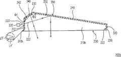
图1A为本发明第一实施例的光源装置的剖面示意图,而图1B为图1A的光源装置的光源模块沿着I-I线的剖面示意图。请参照图1A与图1B,本实施例的光源装置100包括一光源模块200。光源模块200包括一导光柱210。导光柱210具有一第一端面310、一第二端面320、一出光面330、一第一表面340以及一第二表面350。第二端面320与第一端面310相对。出光面330连接于第一端面310与第二端面320之间。第一表面340连接至第一端面310,并与出光面330相对。在本实施例中,第一表面340相对出光面330倾斜。此外,第一表面340与第一端面310在导光柱210内的夹角θ1大于90度且小于180度。第二表面350连接于第一表面340与第二端面320之间,并与出光面330相对,且相对出光面330倾斜。第一表面340与第二表面350在导光柱210内的夹角θ2大于0度且小于180度。1A is a schematic cross-sectional view of a light source device according to a first embodiment of the present invention, and FIG. 1B is a schematic cross-sectional view of a light source module of the light source device in FIG. 1A along line I-I. Please refer to FIG. 1A and FIG. 1B , the
光源模块200还包括一第一发光元件220,其配置于第一端面310旁,并适于发出一第一光束222。在本实施例中,第一发光元件220例如为发光二极管。然而,在其他实施例中,第一发光元件也可以是其他适当的发光元件。第一光束222会由第一端面310进入导光柱210,并经由出光面330传播至导光柱210外。具体而言,在本实施例中,第一表面340上配置有一第一反射单元230。此外,第二表面350上也可配置有一第二反射单元240。第一反射单元230与第二反射单元240例如为反射片或反射膜,其可为一体成型或各自成型。以较大角度偏离发光元件220的光轴A的光束222a可被第一反射单元230反射至出光面330,而以较小角度偏离光轴A的光束222b会被第二反射单元240反射至出光面330。The
在本实施例的光源装置100中,由于以较大角度偏离发光元件220的光轴A的光束222a可被第一反射单元230反射而得以被利用,因此光源装置100具有较高的光利用率。此外,由于发光元件220所发出的点光源在通过导光柱210后,会转变为亮度较为分散的条状光源,因此光源装置100能够有效提升视觉的舒适性。此外,第一端面310与第一表面340的交界线至第一表面340与第二表面350的交界线的距离为L1,而第一表面340与第二表面350的交界线至第二表面350与第二端面320的交界线的距离为L2。为了进一步提升光源装置100的光利用率,在本实施例中,可使L1与L2符合下列关系式:In the
0<L1/L2≦3。0<L1/L2≦3.
在本实施例中,第二端面320上也可配置有一第四反射单元250,以反来自第一端面310的光,进而提升光源装置100的光利用率。此外,导光柱210在第一表面340上可具有图案化光学微结构342。导光柱210在第二表面350上也可具有图案化光学微结构352。再者,导光柱210在第二端面320上也可具有图案化光学微结构322。图案化光学微结构342、352、322可以使光集中或扩散,进而使第一光束222较为均匀地经由出光面330传播至外界。在本实施例中,图案化光学微结构342、352、322包括多个光学微结构,光学微结构例如为在导光柱210表面上的图案化凹点。在本实施例中,每一光学微结构的宽度L3例如为小于或等于10毫米,而深度L4例如为小于或等于10毫米。然而,在其他实施例中,图案化光学微结构也可以是在导光柱表面上呈任何几何形状的凹纹、凸点、凸纹或其他形式的不平滑表面结构。In this embodiment, a
在本实施例中,导光柱210更具有一第八表面360与一第六表面370(如图1B所绘示)。第八表面360连接第一端面310与第二端面320,且连接第一表面340与出光面330,并连接第二表面350与出光面330。第六表面370连接第一端面310与第二端面320,且连接第一表面340与出光面330,并连接第二表面350与出光面330。此外,第八表面360与第六表面370彼此相对。再者,第八表面360上可配置有第五反射单元260与图案化光学微结构362。另外,第六表面370上也可配置有第六反射单元270与图案化光学微结构372。第五反射单元260、第六反射单元270与第二反射单元240可为一体成型或各自成型。In this embodiment, the
在本实施例中,光源装置100还包括一电连接器110,其电连接至光源模块200。具体而言,电连接器110是电连接至第一发光元件220。电连接器110可连接至一灯座(未绘示),灯座所提供的电源可经由电连接器110传递至第一发光元件220,而驱使第一发光元件220发光。在本实施例中,电连接器110、第一发光元件220与导光柱210可通过任何形式的固定架(未绘示)固定在一起。此外,在本实施例中,电连接器110可为一般日光灯管常用的电连接器。举例而言,电连接器110的规格例如为GX-10q或GY-10q。如此一来,便可以用本实施例的光源装置100直接置入传统灯座中来取代传统日光灯管,而不需将传统灯座更换为专为发光二极管设计的新型灯座。In this embodiment, the
值得注意的是,本发明并不限定配置于第一端面310旁的第一发光元件220的数量仅为一个。在其他实施例中,配置于第一端面旁的第一发光元件也可以有多个。此外,本发明并不限定第一表面340上必须配置有第一反射单元230与图案化光学微结构342,且不限定第二表面350上必须配置有第二反射单元240与图案化光学微结构352。在其他实施例中,第一表面与第二表面上可以不配置有反射单元,也可以不具有图案化光学微结构,而第一发光元件所发出的第一光束则在第一表面与第二表面上产生全反射,并被全反射至出光面。It should be noted that the present invention does not limit the number of the first light-emitting
第二实施例second embodiment
图2为本发明第二实施例的光源装置的剖面示意图。请参照图2,本实施例的光源装置100a与上述光源装置100(如图1A所绘示)类似,两者的差异如下所述。在光源装置100a中,光源模块200a的导光柱210a的第一表面340a相对出光面330平行,且第一表面340a与第一端面310在导光柱210a内的夹角θ1’等于90度。光源装置100a具有与光源装置100类似的功效,在此不再重述。FIG. 2 is a schematic cross-sectional view of a light source device according to a second embodiment of the present invention. Referring to FIG. 2 , the light source device 100a of this embodiment is similar to the above-mentioned light source device 100 (shown in FIG. 1A ), and the differences between the two are as follows. In the light source device 100a, the
第三实施例third embodiment
图3A为本发明第三实施例的光源装置的光源模块的剖面示意图,而图3B绘示图3A中的导光柱以其第一端面朝前的侧视示意图。请参照图3A与图3B,本实施例的光源模块200b与上述光源模块200(如图1A所绘示)类似,两者的差异如下所述。在光源模块200b中,导光柱210b在第一端面310b上具有多个光学微结构312,而第一光束222会通过这些光学微结构312。在本实施例中,这些光学微结构312包括圆锥形凹陷312’、椭圆锥形凹陷312”以及多角锥形凹陷312”’。多角锥形凹陷312”’例如是N角锥形凹陷,其中N大于或等于3。这些光学微结构312可以有效降低部分第一光束222被第一端面310b反射或全反射的机会,以使较多比例的第一光束222能够顺利进入导光柱210b中,进而提升光源装置的光利用率。在本实施例中,每一光学微结构312的宽度L3’例如为小于或等于10毫米,而深度L4’例如为小于或等于10毫米。3A is a schematic cross-sectional view of a light source module of a light source device according to a third embodiment of the present invention, and FIG. 3B is a schematic side view of the light guide column in FIG. 3A with its first end facing forward. Please refer to FIG. 3A and FIG. 3B , the
值得注意的是,本发明并不限定光学微结构312必须同时包括圆锥形凹陷312’、椭圆锥形凹陷312”与多角锥形凹陷312”’。在其他实施例中,光学微结构也可以是包括上述各种类凹陷的其中一种以上,或者光学微结构也可以是其他形状的凹陷,例如多面体凹陷、半球状凹陷、各种形式的曲面所形成的凹陷...等。另外,在光源模块200b中,各光学微结构312是彼此相间隔配置。然而,在其他实施例中,各光学微结构也可以是彼此相靠而不间隔地配置。It should be noted that the present invention does not limit the
第四实施例Fourth embodiment
图4A为本发明第四实施例的光源装置的光源模块的剖面示意图,而图4B绘示图4A中的导光柱以其第一端面朝前的侧视示意图。请参照图4A与图4B,本实施例的光源模块200c与上述光源模块200(如图1A所绘示)类似,两者的差异如下所述。在光源模块200c中,导光柱210c在第一端面310c上具有多个同心环状凹纹312c,而第一光束222会通过这些同心环状凹纹312c。在本实施例中,这些同心环状凹纹312c所形成的表面例如为类似菲涅耳透镜(Fresnel lens)的表面,而每一同心环状凹纹312c即落在一菲涅耳区(Fresnel zone)的表面上。然而,在其他实施例中,同心环状凹纹312c所形成的表面也可以是呈其他形式的表面。同心环状凹纹312c具有类似上述光学微结构312(如图3A所绘示)的功效,也能够有效降低第一光束222在第一端面310c上发生反射或全反射的机会。在本实施例中,每一同心环状凹纹312c的宽度L3”例如为小于或等于10毫米,而深度L4”例如为小于或等于10毫米。4A is a schematic cross-sectional view of a light source module of a light source device according to a fourth embodiment of the present invention, and FIG. 4B is a schematic side view of the light guide column in FIG. 4A with its first end facing forward. Please refer to FIG. 4A and FIG. 4B , the light source module 200c of this embodiment is similar to the above-mentioned light source module 200 (shown in FIG. 1A ), and the differences between the two are as follows. In the light source module 200c, the
第五实施例fifth embodiment
图5为本发明第五实施例的光源装置的光源模块的剖面示意图。请参照图5,本实施例的光源模块200d与上述光源模块200(如图1A所绘示)类似,两者的差异如下所述。在光源模块200d中,导光柱210d在第一端面310d上具有一容置凹面312d,以容置第一发光元件220。在本实施例中,容置凹面312d例如为一曲面。容置凹面312d的设计能够使以较大角度偏离第一发光元件220的光轴A的光束222a也能够尽量保持接近垂直地入射容置凹面312d,因此可以有效降低第一光束222在第一端面310d发生反射或全反射的机会,进而有效提升光源装置的光利用率。5 is a schematic cross-sectional view of a light source module of a light source device according to a fifth embodiment of the present invention. Referring to FIG. 5 , the
在其他未绘示的实施例中,容置凹面312d上也可以设有多个上述光学微结构312(如图3A所绘示),而第一光束会通过这些光学微结构312,以进一步提升光源装置的光利用率。此外,本发明并不限定第一端面310d上的容置凹面312d的数量只有一个。在其他实施例中,第一端面上也可以设有多个容置凹面,以容置多个第一发光元件。In other non-illustrated embodiments, a plurality of the above-mentioned optical microstructures 312 (as shown in FIG. 3A ) may also be provided on the accommodating
第六实施例Sixth embodiment
图6A为本发明第六实施例的光源装置的光源模块的剖面示意图,而图6B绘示图6A中的导光柱以其第一端面朝前的侧视示意图。请参照图6A与图6B,本实施例的光源模块200e与上述光源模块200d(如图5所绘示)类似,两者的差异如下所述。在光源模块200e中,导光柱210e在第一端面310e的容置凹面312e上可具有多个同轴环状凹纹312e’,而第一光束222会通过这些同轴环状凹纹312e’,以进一步提升光源装置的光利用率。在本实施例中,这些同轴环状凹纹312e’所形成的表面例如为涅菲耳透镜的表面。然而,在其他实施例中,这些同轴环状凹纹312e’所形成的表面也可以是呈其他适当形式的表面。6A is a schematic cross-sectional view of a light source module of a light source device according to a sixth embodiment of the present invention, and FIG. 6B is a schematic side view of the light guide column in FIG. 6A with its first end facing forward. Please refer to FIG. 6A and FIG. 6B , the
值得注意的是,本发明并不限定容置凹面为曲面。在其他实施例中,其也可以呈其他适当形状。以下将举一实施例详加说明。It should be noted that the present invention does not limit the receiving concave surface to be a curved surface. In other embodiments, it may also take other suitable shapes. An example will be given below to describe in detail.
第七实施例Seventh embodiment
图7为本发明第七实施例的光源装置的光源模块的剖面示意图。请参照图7,本实施例的光源模块200f与上述光源模块200d(如图5所绘示)类似,两者的差异如下所述。在光源模块200f中,导光柱210f的第一端面310f上的容置凹面312f包括一底面313a及至少一侧面313b,而侧面313b连接至底面313a。在本实施例中,底面313a上可设有多个上述光学微结构312。然而,在其他实施例中,容置凹面的底面也可以是一平滑面,而其上不设置光学微结构。7 is a schematic cross-sectional view of a light source module of a light source device according to a seventh embodiment of the present invention. Referring to FIG. 7 , the light source module 200f of this embodiment is similar to the above-mentioned
第八实施例Eighth embodiment
图8为本发明第八实施例的光源装置的光源模块的剖面示意图。请参照图8,本实施例的光源模块200g与上述光源模块200(如图1A所绘示)类似,两者的差异如下所述。在光源模块200g中,导光柱210g在第一表面340g、第二表面350g及第二端面320g上没有图案化光学微结构,取而代之的是,导光柱210g在第一表面340g、第二表面350g及第二端面320g上分别配置有扩散层342g、352g及322g。扩散层342g、352g及322g也具有光扩散的功效。8 is a schematic cross-sectional view of a light source module of a light source device according to an eighth embodiment of the present invention. Please refer to FIG. 8 , the
第九实施例Ninth embodiment
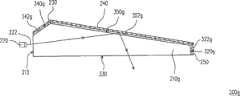
图9为本发明第九实施例的光源装置的光源模块的剖面示意图。请参照图9,本实施例的光源模块200h与上述光源模块200(如图1A所绘示)类似,两者的差异如下所述。在光源模块200h中,导光柱210h更具有一第三表面380,其连接于第一端面310与出光面330之间,并与第一表面340相对。第三表面380与第一端面310在导光柱210h内的夹角θ3大于90度且小于180度。在本实施例中,导光柱210h在第三表面380上可具有图案化光学微结构382。图案化光学微结构382可类似于上述图案化光学微结构342。然而,在其他实施例中,也可以用扩散层来取代图案化光学微结构382。此外,在本实施例中,第三表面380上可配置有第三反射单元280。9 is a schematic cross-sectional view of a light source module of a light source device according to a ninth embodiment of the present invention. Referring to FIG. 9 , the
在光源模块200h中,相对光束222a以相反方向偏离光轴A的光束222c可在第三表面380上产生反射,且接着传递至第二表面350并产生反射,最后经由出光面330传播至导光柱210h外。因此,光源模块200h可以进一步善加利用光束222c,而使光源装置具有更好的光利用率。In the
第十实施例Tenth embodiment
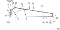
图10为本发明第十实施例的光源装置的光源模块的剖面示意图。请参照图10,本实施例的光源模块200i与上述光源模块200(请参照图1A)部分类似,两者的差异处如下所述。在光源模块200i中,导光柱210i更具有一第四表面390以及一第五表面410。第四表面390连接至第二表面350,并与出光面330相对,且相对出光面330倾斜。第二表面350与第四表面390在导光柱内的夹角θ4大于180度且小于360度。第五表面410连接于第四表面390与第二端面320i之间,并与出光面330相对。第四表面390与第五表面410在导光柱210i内的夹角θ5大于0度且小于180度。在本实施例中,第五表面410相对出光面330倾斜,且第五表面410与第二端面320i在导光柱210i内的夹角θ6大于90度且小于180度。然而,在其他未绘示的实施例中,第五表面410也可相对出光面330平行,且第五表面410与第二端面320i在导光柱210i内的夹角θ6等于90度。10 is a schematic cross-sectional view of a light source module of a light source device according to a tenth embodiment of the present invention. Please refer to FIG. 10 , the light source module 200i of this embodiment is partially similar to the above-mentioned light source module 200 (please refer to FIG. 1A ), and the differences between the two are as follows. In the light source module 200i, the
光源模块210i可更包括至少一第二发光元件510,其配置于第二端面320i旁,并适于发出一第二光束512。第二光束512会由第二端面320i进入导光柱210i,并经由出光面330传播至导光柱210i外。在本实施例中,第四表面390、第五表面410与第二端面320i可分别对称于第二表面350、第一表面340与第一端面310。如此的设计可以使导光柱210i延长,并同时兼具光源装置所提供的光束的均匀性。此外,由于本实施例的光源模块200i具有两个发光元件(即第一发光元件220与第二发光元件510),因此可提升光源装置的亮度。然而,在其他实施例中,第四表面、第五表面与第二端面也可不对称于第二表面、第一表面与第一端面。The
在本实施例中,第四表面390与第五表面410上也可分别设有图案化光学微结构392及412,且可分别设有第七反射单元290与第八反射单元520。然而,在其他实施例中,第四表面与第五表面上也可不配置有图案化光学微结构与反射单元,且第四表面与第五表面可以是以全反射的方式将第二光束反射。In this embodiment, patterned
第十一实施例Eleventh embodiment
图11为本发明第十一实施例的光源装置的光源模块的剖面示意图。请参照图11,本实施例的光源模块200j与上述光源模块200i(如图10所绘示)类似,两者的差异如下所述。在光源模块200j中,导光柱210j更包括一第七表面420,其连接于第二端面320i与出光面330之间,并与第五表面410相对。第七表面420与第二端面320i在导光柱210j内的夹角θ7大于90度且小于180度。在本实施例中,第七表面420与第四表面380对称。但在其他实施例中,第七表面420也可以不对称于第四表面380。此外,在本实施例中,第七表面420上可设有图案化光学微结构422与第九反射单元530。11 is a schematic cross-sectional view of a light source module of a light source device according to an eleventh embodiment of the present invention. Referring to FIG. 11 , the
第十二实施例Twelfth embodiment
请参照图1B,本发明并不限定第二表面350、第八表面360、第六表面370与出光面330为平面。在其他实施例中,第二表面、第八表面、第六表面与出光面也可以是皆为曲面,或者也可以是部分为曲面,部分为平面。以下将举一实施例详加说明。Please refer to FIG. 1B , the present invention does not limit the
图12为本发明第十二实施例的光源装置的光源模块的剖面示意图。请参照图12,本实施例的光源模块200k与上述光源模块200(如图1B所绘示)类似,两者的差异如下所述。在光源模块200k中,导光柱210k的第二表面350k、第八表面360k与第六表面370k皆为曲面,而出光面330为平面。此外,第二反射单元240k、第五反射单元260k与第六反射单元270k的形状可分别随着第二表面350k、第八表面360k与第六表面370k的形状弯曲。再者,光源模块200k在沿着导光柱210k的纵长方向上的一剖面与图1A所绘示者形状相同。12 is a schematic cross-sectional view of a light source module of a light source device according to a twelfth embodiment of the present invention. Referring to FIG. 12 , the
第十三实施例Thirteenth embodiment
图13为本发明第十三实施例的光源装置的剖面示意图。请参照图1A与图13,本实施例的光源装置100l与上述光源装置100类似,两者的差异如下所述。在光源装置100中,第二端面320的法向量N1与出光面330的法向量N2可互相垂直。然而,在光源装置100l的光源模块200l的导光柱210l中,第二端面320l的法向量N1’与出光面330的法向量N2的夹角θ8大于90度且小于180度。13 is a schematic cross-sectional view of a light source device according to a thirteenth embodiment of the present invention. Please refer to FIG. 1A and FIG. 13 , the
第十四实施例Fourteenth embodiment
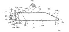
图14A为本发明第十四实施例的光源装置的光源模块的剖面示意图,而图14B为图14A中的导光柱的立体示意图。请参照图14A与图14B,本实施例的光源模块200m与上述光源模块200e(请参照图6A)类似,两者的差异如下所述。在光源模块200m中,导光柱210m具有一环状表面340m以取代图6A中的导光柱210e的第一表面340。环状表面340m连接至第一端面310m,出光面330连接于环状表面340m与第二端面320m之间,而第二表面350m连接于环状表面340m与第二端面320m之间。在本实施例中,环状表面340m与第二表面350m之间有段差,且环状表面340m与出光面330之间有段差。环状表面340m的功效类似于图9的第一表面340与第三表面380,环状表面340m可将以较大角度偏离第一发光元件220的光轴A的第一光束222反射,而使其能够被利用。在其他实施例中,也可以是环状表面的一部分与第二表面之间有段差,而另一部分没有段差。此外,在其他实施例中,也可以是环状表面的一部分与出光面之间有段差,而另一部分没有段差。再者,在本实施例中,环状表面340m上可配置有第一反射单元230m,以反射第一光束222。然而,在其他实施例中,环状表面上也可以不配置有反射单元,而环状表面是以全反射的方式将第一光束反射。FIG. 14A is a schematic cross-sectional view of a light source module of a light source device according to a fourteenth embodiment of the present invention, and FIG. 14B is a schematic perspective view of a light guide column in FIG. 14A . Please refer to FIG. 14A and FIG. 14B , the
在本实施例中,第二表面350m是平行于出光面330。然而,在其他实施例中,第二表面也可以相对出光面倾斜。此外,在本实施例中,导光柱210m在第二表面350m上具有一图案化光学微结构352m。具体而言,图案化光学微结构352m包括多个凹纹353m。导光柱210m是沿着一第一方向D1由第一端面310m往第二端面320m延伸。每一凹纹353m沿着一与第一方向D1垂直的第二方向D2延伸,且这些凹纹353m沿着第一方向D1排列。在本实施例中,每一凹纹353m可由一微倾斜面355m与一微垂直面357m所形成,其中微倾斜面355m相对出光面330倾斜,而微垂直面357m则垂直于出光面330。在本实施例中,每一凹纹353m的宽度L3”’例如为小于或等于10毫米,而深度L4”’例如为小于或等于10毫米。In this embodiment, the
在本实施例中,第一端面310m具有一容置凹面312m,以容置第一发光元件220。具体而言,容置凹面312m可由多个同轴环状子表面313m所构成,而相邻两子表面313m之间有一夹角。在其他实施例中,容置凹面也可以是球面、非球面、其他曲面、多面体状凹面或其他形式的凹面。In this embodiment, the
在本实施例中,环状表面340m呈圆环状。然而,在其他实施例中,环状表面也可以呈多边形环状或其他形式的环状。此外,在本实施例中,环状表面340m为平滑表面。然而,在其他实施例中,环状表面也可以是类似涅菲耳透镜的表面,亦即包括多个涅菲耳区的表面。或者,环状表面上也可以有上述图案化光学微结构。In this embodiment, the
在本实施例中,第二端面320m的法向量N1”与出光面330的法向量N2的夹角θ8’大于90度且小于180度。当导光柱210m是以注塑成型制成时,为了便于成型,导光柱210m可更具有一连接面430m,连接于第二端面320m与出光面330之间。此外,在本实施例中,第二端面320m为一平面。然而,在其他实施例中,第二端面上也可以有上述图案化光学微结构,或者第二端面也可为一曲面。In this embodiment, the angle θ8' between the normal vector N1" of the
第十五实施例Fifteenth embodiment
图15为本发明第十五实施例的光源装置的剖面示意图。请参照图15,本实施例的光源装置100n与上述光源装置100l(如图13所绘示)类似,两者的差异如下所述。在光源装置100n中,光源模块200n的导光柱210n不具有图13中的第一表面340,而第二表面350直接连接至第一端面310。15 is a schematic cross-sectional view of a light source device according to a fifteenth embodiment of the present invention. Please refer to FIG. 15 , the light source device 100 n of this embodiment is similar to the above-mentioned light source device 100 l (as shown in FIG. 13 ), and the differences between the two are as follows. In the light source device 100 n , the light guide column 210 n of the light source module 200 n does not have the
第十六实施例Sixteenth embodiment
图16为本发明第十六实施例的光源装置中的导光柱的立体示意图。请参照图16,本实施例的导光柱210o与上述导光柱210m(如图14A所绘示)类似,两者的差异如下所述。在导光柱210o中,第二端面320o包括多个子端面324a、324b。在本实施例中,每一子端面324a、324b为平面,且相邻两子端面324a、324b在导光柱210o内的夹角大于0度且小于180度。此外,连接面430o连接于子端面324a与出光面330之间,并连接于子端面324b与出光面330之间。然而,在其他实施例中,第二端面的子端面也可以是曲面。FIG. 16 is a schematic perspective view of a light guide column in a light source device according to a sixteenth embodiment of the present invention. Referring to FIG. 16 , the light guide column 210o of this embodiment is similar to the above-mentioned
本发明并不限定一光源装置仅能具有一光源模块。在其他实施例中,一光源装置也可以具有多个光源模块。以下将举两个实施例详加说明。The present invention does not limit a light source device to only have one light source module. In other embodiments, a light source device may also have multiple light source modules. Two examples will be cited below to describe in detail.
第十七实施例Seventeenth embodiment
图17为本发明第十七实施例的光源装置以其导光柱的出光面朝前的正视示意图。请参照图17,本实施例的光源装置100p包括多个上述光源模块200。每一光源模块200的导光柱210沿着一第一方向D1延伸,且这些光源模块200的这些导光柱210沿着一与第一方向D1垂直的第二方向D2排列。在本实施例中,每一光源模块200电连接至电连接器110。此外,各光源模块200与电连接器110可通过固定架(未绘示)固定为一体。17 is a schematic front view of a light source device according to a seventeenth embodiment of the present invention with the light emitting surface of the light guide column facing forward. Please refer to FIG. 17 , the
第十八实施例Eighteenth embodiment
图18为本发明第十八实施例的光源装置以其导光柱的出光面朝前的正视示意图。请参照图18,本实施例的光源装置100q与上述光源装置100p(如图17所绘示)类似,两者的差异如下所述。在光源装置100q中,这些光源模块200的这些导光柱210是沿着第一方向D1(即每一导光柱210的延伸方向)排列。FIG. 18 is a schematic front view of a light source device according to an eighteenth embodiment of the present invention with the light emitting surface of the light guide column facing forward. Please refer to FIG. 18 , the light source device 100q of this embodiment is similar to the above-mentioned
值得注意的是,本发明并不限定各光源模块的排列方式。在其他实施例中,各光源模块也可以以不同于上述两种方式的排列方式排列。此外,光源装置100p与光源装置100q中的光源模块200也可以用上述其他实施例的光源模块取代,以形成多种不同的光源装置。It should be noted that the present invention does not limit the arrangement of each light source module. In other embodiments, the light source modules can also be arranged in an arrangement different from the above two arrangements. In addition, the
综上所述,在本发明一实施例的光源装置中,发光元件所发出的光会经过导光柱而转换为亮度较为分散的条状光源,进而增加视觉的舒适性。此外,以较大角度偏离发光元件的光轴的光线能够被第一表面或环状表面全反射或被配置于第一表面或环状表面上的反射单元反射,所以偏离光轴的光线仍能够被有效地利用,进而提升光源装置的光利用率。在本发明一实施例的光源装置中,导光柱的第一端面上可配置有光学微结构、环状凹纹或容置凹面,以提升发光元件所发出的光进入导光柱的比例,进而提升光源装置的光利用率。To sum up, in the light source device according to an embodiment of the present invention, the light emitted by the light-emitting element will be converted into a strip-shaped light source with relatively dispersed brightness through the light guide rod, thereby increasing visual comfort. In addition, the light that deviates from the optical axis of the light-emitting element at a large angle can be totally reflected by the first surface or the annular surface or reflected by the reflection unit configured on the first surface or the annular surface, so the light that deviates from the optical axis can still be be effectively utilized, thereby improving the light utilization rate of the light source device. In the light source device according to an embodiment of the present invention, the first end surface of the light guide column may be provided with optical microstructures, annular grooves or accommodating concave surfaces, so as to increase the proportion of light emitted by the light-emitting element entering the light guide column, thereby improving The light utilization rate of the light source device.
虽然结合以上多个实施例揭露本发明,然而其并非用以限定本发明,任何所属技术领域中熟悉此技术者,在不脱离本发明的精神和范围内,可作些许的更动与润饰,因此本发明的保护范围应以所附的权利要求所界定的为准。Although the present invention is disclosed in conjunction with the above multiple embodiments, it is not intended to limit the present invention. Anyone skilled in the art can make some changes and modifications without departing from the spirit and scope of the present invention. Therefore, the scope of protection of the present invention should be defined by the appended claims.
Claims (25)
Translated fromChinesePriority Applications (1)
| Application Number | Priority Date | Filing Date | Title |
|---|---|---|---|
| CN200810085351ACN101532641A (en) | 2008-03-14 | 2008-03-14 | Light source device |
Applications Claiming Priority (1)
| Application Number | Priority Date | Filing Date | Title |
|---|---|---|---|
| CN200810085351ACN101532641A (en) | 2008-03-14 | 2008-03-14 | Light source device |
Publications (1)
| Publication Number | Publication Date |
|---|---|
| CN101532641Atrue CN101532641A (en) | 2009-09-16 |
Family
ID=41103400
Family Applications (1)
| Application Number | Title | Priority Date | Filing Date |
|---|---|---|---|
| CN200810085351APendingCN101532641A (en) | 2008-03-14 | 2008-03-14 | Light source device |
Country Status (1)
| Country | Link |
|---|---|
| CN (1) | CN101532641A (en) |
Cited By (2)
| Publication number | Priority date | Publication date | Assignee | Title |
|---|---|---|---|---|
| CN102734655A (en)* | 2011-04-15 | 2012-10-17 | 东莞万士达液晶显示器有限公司 | Light source module |
| CN103712095A (en)* | 2012-10-02 | 2014-04-09 | 胜华科技股份有限公司 | lighting device |
- 2008
- 2008-03-14CNCN200810085351Apatent/CN101532641A/enactivePending
Cited By (2)
| Publication number | Priority date | Publication date | Assignee | Title |
|---|---|---|---|---|
| CN102734655A (en)* | 2011-04-15 | 2012-10-17 | 东莞万士达液晶显示器有限公司 | Light source module |
| CN103712095A (en)* | 2012-10-02 | 2014-04-09 | 胜华科技股份有限公司 | lighting device |
Similar Documents
| Publication | Publication Date | Title |
|---|---|---|
| CN102472454B (en) | Light-guiding plate, light-guiding plate manufacturing method, surface light-source device, and liquid crystal display device | |
| CN101644415B (en) | Light guide plate and backlight module | |
| CN101191905B (en) | Light bar, backlight module and display using the same | |
| JP5089960B2 (en) | Surface light source device, backlight unit including the same, and liquid crystal display device including the backlight unit | |
| KR20130117645A (en) | Light-guide panel, planar light-source device, and display device | |
| CN103375741A (en) | Light guide plate and backlight module using same | |
| CN104121517A (en) | Backlight module | |
| CN104932140A (en) | Backlight module | |
| CN104132304A (en) | Optical lens | |
| CN104747938A (en) | Lighting device using line shaped beam | |
| TWI331666B (en) | Light source apparatus | |
| KR20140060625A (en) | Light emitting device and lighting device having the same | |
| CN204285310U (en) | Optical lens, lamp bar and down straight aphototropism mode set | |
| CN202382107U (en) | Backlight module and liquid crystal display equipment using same | |
| CN101235953A (en) | Lens structure and light emitting unit | |
| CN1963624A (en) | Backlight module | |
| TW201426125A (en) | Light guide plate and backlight module | |
| CN102162868B (en) | Optical sheet and backlight module with optical sheet | |
| CN205581468U (en) | Side-entry backlight module and liquid crystal display device | |
| CN101532641A (en) | Light source device | |
| CN104122617A (en) | Light guide plate and backlight module | |
| TWI485483B (en) | Light-guiding plate, light emitting module and display apparatus | |
| CN202691910U (en) | Omnidirectional projected light guide column structure | |
| TWI338110B (en) | Light source apparatus | |
| CN207008107U (en) | Light guide part of lamp |
Legal Events
| Date | Code | Title | Description |
|---|---|---|---|
| C06 | Publication | ||
| PB01 | Publication | ||
| C10 | Entry into substantive examination | ||
| SE01 | Entry into force of request for substantive examination | ||
| C02 | Deemed withdrawal of patent application after publication (patent law 2001) | ||
| WD01 | Invention patent application deemed withdrawn after publication | Open date:20090916 |