CN101526127A - A continuously variable transmission - Google Patents
A continuously variable transmissionDownload PDFInfo
- Publication number
- CN101526127A CN101526127ACNA2009100066277ACN200910006627ACN101526127ACN 101526127 ACN101526127 ACN 101526127ACN A2009100066277 ACNA2009100066277 ACN A2009100066277ACN 200910006627 ACN200910006627 ACN 200910006627ACN 101526127 ACN101526127 ACN 101526127A
- Authority
- CN
- China
- Prior art keywords
- support
- disc
- shaft
- grooves
- continuously variable
- Prior art date
- Legal status (The legal status is an assumption and is not a legal conclusion. Google has not performed a legal analysis and makes no representation as to the accuracy of the status listed.)
- Granted
Links
Images


Classifications
- F—MECHANICAL ENGINEERING; LIGHTING; HEATING; WEAPONS; BLASTING
- F16—ENGINEERING ELEMENTS AND UNITS; GENERAL MEASURES FOR PRODUCING AND MAINTAINING EFFECTIVE FUNCTIONING OF MACHINES OR INSTALLATIONS; THERMAL INSULATION IN GENERAL
- F16H—GEARING
- F16H15/00—Gearings for conveying rotary motion with variable gear ratio, or for reversing rotary motion, by friction between rotary members
- F16H15/48—Gearings for conveying rotary motion with variable gear ratio, or for reversing rotary motion, by friction between rotary members with members having orbital motion
- F16H15/50—Gearings providing a continuous range of gear ratios
- F16H15/52—Gearings providing a continuous range of gear ratios in which a member of uniform effective diameter mounted on a shaft may co-operate with different parts of another member
- F—MECHANICAL ENGINEERING; LIGHTING; HEATING; WEAPONS; BLASTING
- F16—ENGINEERING ELEMENTS AND UNITS; GENERAL MEASURES FOR PRODUCING AND MAINTAINING EFFECTIVE FUNCTIONING OF MACHINES OR INSTALLATIONS; THERMAL INSULATION IN GENERAL
- F16H—GEARING
- F16H15/00—Gearings for conveying rotary motion with variable gear ratio, or for reversing rotary motion, by friction between rotary members
- F16H15/02—Gearings for conveying rotary motion with variable gear ratio, or for reversing rotary motion, by friction between rotary members without members having orbital motion
- F16H15/04—Gearings providing a continuous range of gear ratios
- B—PERFORMING OPERATIONS; TRANSPORTING
- B62—LAND VEHICLES FOR TRAVELLING OTHERWISE THAN ON RAILS
- B62M—RIDER PROPULSION OF WHEELED VEHICLES OR SLEDGES; POWERED PROPULSION OF SLEDGES OR SINGLE-TRACK CYCLES; TRANSMISSIONS SPECIALLY ADAPTED FOR SUCH VEHICLES
- B62M11/00—Transmissions characterised by the use of interengaging toothed wheels or frictionally-engaging wheels
- B62M11/04—Transmissions characterised by the use of interengaging toothed wheels or frictionally-engaging wheels of changeable ratio
- B62M11/12—Transmissions characterised by the use of interengaging toothed wheels or frictionally-engaging wheels of changeable ratio with frictionally-engaging wheels
- F—MECHANICAL ENGINEERING; LIGHTING; HEATING; WEAPONS; BLASTING
- F16—ENGINEERING ELEMENTS AND UNITS; GENERAL MEASURES FOR PRODUCING AND MAINTAINING EFFECTIVE FUNCTIONING OF MACHINES OR INSTALLATIONS; THERMAL INSULATION IN GENERAL
- F16H—GEARING
- F16H15/00—Gearings for conveying rotary motion with variable gear ratio, or for reversing rotary motion, by friction between rotary members
- F16H15/02—Gearings for conveying rotary motion with variable gear ratio, or for reversing rotary motion, by friction between rotary members without members having orbital motion
- F16H15/04—Gearings providing a continuous range of gear ratios
- F16H15/06—Gearings providing a continuous range of gear ratios in which a member A of uniform effective diameter mounted on a shaft may co-operate with different parts of a member B
- F16H15/26—Gearings providing a continuous range of gear ratios in which a member A of uniform effective diameter mounted on a shaft may co-operate with different parts of a member B in which the member B has a spherical friction surface centered on its axis of revolution
- F16H15/28—Gearings providing a continuous range of gear ratios in which a member A of uniform effective diameter mounted on a shaft may co-operate with different parts of a member B in which the member B has a spherical friction surface centered on its axis of revolution with external friction surface
- F—MECHANICAL ENGINEERING; LIGHTING; HEATING; WEAPONS; BLASTING
- F16—ENGINEERING ELEMENTS AND UNITS; GENERAL MEASURES FOR PRODUCING AND MAINTAINING EFFECTIVE FUNCTIONING OF MACHINES OR INSTALLATIONS; THERMAL INSULATION IN GENERAL
- F16H—GEARING
- F16H61/00—Control functions within control units of change-speed- or reversing-gearings for conveying rotary motion ; Control of exclusively fluid gearing, friction gearing, gearings with endless flexible members or other particular types of gearing
- F16H61/66—Control functions within control units of change-speed- or reversing-gearings for conveying rotary motion ; Control of exclusively fluid gearing, friction gearing, gearings with endless flexible members or other particular types of gearing specially adapted for continuously variable gearings
- F16H61/664—Friction gearings
- F16H61/6649—Friction gearings characterised by the means for controlling the torque transmitting capability of the gearing
- F—MECHANICAL ENGINEERING; LIGHTING; HEATING; WEAPONS; BLASTING
- F16—ENGINEERING ELEMENTS AND UNITS; GENERAL MEASURES FOR PRODUCING AND MAINTAINING EFFECTIVE FUNCTIONING OF MACHINES OR INSTALLATIONS; THERMAL INSULATION IN GENERAL
- F16H—GEARING
- F16H63/00—Control outputs from the control unit to change-speed- or reversing-gearings for conveying rotary motion or to other devices than the final output mechanism
- F16H63/02—Final output mechanisms therefor; Actuating means for the final output mechanisms
- F16H63/04—Final output mechanisms therefor; Actuating means for the final output mechanisms a single final output mechanism being moved by a single final actuating mechanism
- F16H63/06—Final output mechanisms therefor; Actuating means for the final output mechanisms a single final output mechanism being moved by a single final actuating mechanism the final output mechanism having an indefinite number of positions
- F16H63/067—Final output mechanisms therefor; Actuating means for the final output mechanisms a single final output mechanism being moved by a single final actuating mechanism the final output mechanism having an indefinite number of positions mechanical actuating means
Landscapes
- Engineering & Computer Science (AREA)
- General Engineering & Computer Science (AREA)
- Mechanical Engineering (AREA)
- Chemical & Material Sciences (AREA)
- Combustion & Propulsion (AREA)
- Transportation (AREA)
- Friction Gearing (AREA)
- General Details Of Gearings (AREA)
- Valve Device For Special Equipments (AREA)
- Valve-Gear Or Valve Arrangements (AREA)
- Electrical Discharge Machining, Electrochemical Machining, And Combined Machining (AREA)
- Retarders (AREA)
Abstract
Description
Translated fromChinese本申请为国际申请日为2002年4月25日、标题为连续可变变速器且国际申请号为PCT/US02/13399、国家申请号为02809761.0的专利申请的分案申请。This application is a divisional application of a patent application whose international filing date is April 25, 2002, titled continuously variable transmission, international application number PCT/US02/13399, and national application number 02809761.0.
技术领域technical field
本发明的领域通常涉及变速器,并且更具体地说本发明涉及连续可变变速器。The field of the invention relates generally to transmissions, and more particularly the invention relates to continuously variable transmissions.
背景技术Background technique
本发明涉及连续可变变速器领域,并且包括几个取得进步并且优于现有技术的新颖特征和具有创造性的方面。为了提供一种无级可变变速器,已经开发出各种牵引滚轮(traction roller)变速器,其中通过支撑在壳体中的牵引滚轮在扭矩输入和输出盘之间传递动力。在这种变速器中,牵引滚轮安装在支撑结构中,这些支撑结构在绕枢轴转动时根据所要求的传动比使得牵引滚轮在直径不同的圆周运动中与扭矩盘(torque disk)啮合。The present invention relates to the field of continuously variable transmissions and includes several novel features and inventive aspects that advance and provide advantages over the prior art. In order to provide a continuously variable transmission, various traction roller transmissions have been developed in which power is transmitted between torque input and output discs through traction rollers supported in a housing. In such transmissions, the traction rollers are mounted in support structures which, when pivoted, cause the traction rollers to mesh with torque disks in circular motions of varying diameters according to the desired transmission ratio.
但是,这些传统的解决方案具有局限性。例如,在一个解决方案中,披露了一种具有可变可调传动比的汽车用驱动轮毂。该方法指导使用两块隔板(iris plate),在这些牵引滚轮的每一侧上一块,从而使得这些滚轮的每一个的转轴倾斜。但是,由于在变速器换挡期间调节这些隔板所需要的零件数量较大,所以隔板的使用非常复杂。这种变速器的另一个难题在于,它具有一导环,其构成主要是相对于每个滚轮固定。由于该导环是固定的,所以难以改变每个牵引滚轮的转轴。However, these traditional solutions have limitations. For example, in one solution, a drive hub for a vehicle with a variable adjustable transmission ratio is disclosed. The method directs the use of two iris plates, one on each side of the traction rollers, so that the axis of rotation of each of the rollers is inclined. However, the use of spacers is complicated by the large number of parts required to adjust these spacers during transmission shifts. Another difficulty with this type of transmission is that it has a guide ring which is essentially constituted fixed relative to each roller. Since the guide ring is fixed, it is difficult to change the rotation axis of each traction roller.
对这种早期结构的一个改进之处是一个主动部件和从动部件围绕转动的轴。该主动部件和从动部件都安装在该轴上,并且接触径向围绕该轴等距设置的多个动力调节器。这些动力调节器与这两个部件摩擦接触,并且从主动部件将动力传递给从动部件。同心设在轴上并且位于动力调节器之间的支撑部件施加作用力,从而使这些动力调节器分离以便能够摩擦接触主动部件和从动部件。这种结构的缺点在于,缺少用于在该变速器上的扭矩负载改变时产生足够的轴向力以使主动和从动部件与动力调节器保持足够的摩擦接触的装置。该结构的另一个缺点是在高扭矩和非常低速度情况下。以及变速器分离和滑行装置能力不够时导致换挡困难。An improvement over this earlier structure was an axis around which the driving and driven parts rotate. Both the driving part and the driven part are mounted on the shaft and contact a plurality of power regulators arranged radially equidistant around the shaft. These power regulators are in frictional contact with the two components and transmit power from the driving component to the driven component. A support member located concentrically on the shaft and between the power regulators exerts a force that separates the power regulators to enable frictional contact of the driving and driven parts. A disadvantage of this construction is the lack of means for generating sufficient axial force to maintain sufficient frictional contact of the driving and driven components with the power regulator as the torque load on the transmission changes. Another disadvantage of this structure is at high torque and very low speed. And when the transmission is disengaged and the capacity of the coasting device is insufficient, it will cause difficulty in shifting gears.
因此,需要一种连续可变变速器,它具有改进的动力调节器支撑件和换挡机构、针对不同扭矩和动力负载向主动和从动部件施加适当轴向推力的装置以及使离合器分离和再啮合以便滑行的装置。Therefore, there is a need for a continuously variable transmission having an improved power modulator support and shift mechanism, means to apply appropriate axial thrust to the driving and driven components for different torques and power loads, and to disengage and re-engage the clutches device for sliding.
发明内容Contents of the invention
这些系统和方法具有几个特征,其中任何单个特征都不单独对其所要求的属性负责。在不限制由下面权利要求所示范围的情况下,现在简要地对其比较突出的特征进行说明。在研究了该说明书之后,尤其在阅读了题为“优选实施方案的详细说明”的部分之后,人们将理解这些系统和方法的特征是如何达到优于传统系统和方法的几个优点的。These systems and methods have several features, no single one of which is solely responsible for their claimed attributes. Without limiting the scope indicated by the following claims, its more prominent features will now be briefly described. After studying this specification, and particularly after reading the section entitled "Detailed Description of the Preferred Embodiments," one will understand how the features of these systems and methods achieve several advantages over conventional systems and methods.
在一个方面,披露了一种连续可变变速器,它具有一纵轴和多个调速器。每个调速器具有一从纵轴径向向外设置的可倾斜转轴。另外还设置有一主动盘,它可以绕着纵轴环形转动并且接触调速器中每一个上的第一点;还有一支撑部件,它同样可绕着纵轴环形转动。设置一个支承盘和至少两个轴向力产生装置,前者也可绕着纵轴环形转动。轴向力产生装置设置在主动盘和支承盘之间,并且构成每个轴向力产生装置以向主动盘施加轴向力。In one aspect, a continuously variable transmission is disclosed having a longitudinal shaft and a plurality of governors. Each governor has a tiltable shaft disposed radially outward from the longitudinal axis. Also provided is a driving disc which is circularly rotatable about the longitudinal axis and contacts the first point on each of the speed governors; and a support member which is also circularly rotatable about the longitudinal axis. A support disk and at least two axial force generating devices are provided, the former also being rotatable in a ring about the longitudinal axis. Axial force generating devices are arranged between the drive disc and the support disc, and constitute each axial force generating device to apply axial force to the drive disc.
在另一个方面中,除了分离机构外,还披露了一种绕着纵轴环形转动的支承盘。分离机构可以设置在支承盘和主动盘之间,并且适合使主动盘与调速器分离。In another aspect, in addition to the decoupling mechanism, a support disc is disclosed that rotates annularly about a longitudinal axis. A separation mechanism may be provided between the support disc and the driving disc, and is adapted to separate the driving disc from the governor.
在还有一个方面中,除了可绕着变速器纵轴环形转动的支承盘外,还披露了一种输出盘或转动毂套。包括有一支撑部件,它也可以绕着纵轴环形转动,并且适合朝向更缓慢转动的主动盘或输出盘中的任一个移动。In yet another aspect, an output disc or rotating hub is disclosed in addition to a support disc that is annularly rotatable about the longitudinal axis of the variator. A support member is included which is also circularly rotatable about a longitudinal axis and adapted to move towards either the more slowly rotating drive or output discs.
在又一个方面中,披露了一种具有钩的连接组件,其中钩连接到主动盘或支承盘上。还包括一连接到主动盘或支承盘上的卡锁(latch)。In yet another aspect, a connection assembly having a hook is disclosed, wherein the hook is connected to a drive or support disk. Also included is a latch attached to the driving disc or the support disc.
在更有一个方面中,披露了多根具有两个端部的轴,其中一根轴设置在每个调速器的孔中,并且设有多个具有平台端部和轴端部的轴支撑件。每个轴支撑件与其中一根轴的两个端部中的一个可操作啮合。另外还设有多个轴支撑轮,其中为每个轴支撑件设置至少一个轴支撑轮。包括有环形第一和第二固定支撑件,每个支撑件具有面对调速器的第一侧面和背对调速器的第二侧面。第一和第二固定支撑件的每一个在第一侧面上具有一凹面,并且第一固定支撑件靠近主动盘设置,而第二固定支撑件则靠近从动盘设置。In yet another aspect, a plurality of two-ended shafts is disclosed, with one shaft disposed in the bore of each governor, and a plurality of shaft supports having a platform end and a shaft end pieces. Each shaft support is operatively engaged with one of the two ends of one of the shafts. In addition, a plurality of axle support wheels are provided, wherein at least one axle support wheel is provided for each axle support. Included are annular first and second stationary supports, each having a first side facing the governor and a second side facing away from the governor. Each of the first and second fixed supports has a concave surface on the first side, and the first fixed support is disposed close to the driving disc, and the second fixed support is disposed close to the driven disc.
另外,还还披露了一种连续可变变速器,它具有一盘簧,该盘簧设置在支承盘和主动盘之间。In addition, a continuously variable transmission is also disclosed, which has a coil spring arranged between the support disc and the drive disc.
在又一个方面中,披露了一种变速器换挡机构,它包括一杆件;具有一组外螺纹的蜗杆件;具有一组内螺纹的换挡管,其中换挡管的转动引起传动比变化;一套筒,它具有一组内螺纹;以及一分轴,它具有一螺纹端。In yet another aspect, a transmission shift mechanism is disclosed, which includes a rod member; a worm member with a set of external threads; a shift tube with a set of internal threads, wherein the rotation of the shift tube causes a change in transmission ratio ; a sleeve, which has a set of internal threads; and a shaft, which has a threaded end.
在还有一个方面中,披露了一种遥控变速器换挡装置,它包括一转动操纵把手;具有第一端部和第二端部的系绳,其中第一端部与操纵把手接合而第二端部与换挡管接合。该操纵把手适于向系绳施加拉力,而系绳在施加拉力时作动换挡管。In yet another aspect, a remote transmission shifter is disclosed that includes a rotary operating handle; a tether having a first end and a second end, wherein the first end engages the operating handle and the second The end engages the shift tube. The operating handle is adapted to apply a pulling force to the tether, and the tether actuates the shift tube when the pulling force is applied.
本领域的普通技术人员在他们阅读以下详细说明及附图后对本发明的这些和其它改进之处更加清楚。These and other improvements in the invention will become apparent to those of ordinary skill in the art upon their reading of the following detailed description and accompanying drawings.
附图说明Description of drawings
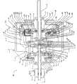
图1为变速器一个实施方案的剖开侧视图;Figure 1 is a cutaway side view of one embodiment of a transmission;
图2为图1线II-II剖取出的局部端部剖视图;Fig. 2 is a partial end sectional view taken from line II-II of Fig. 1;
图3为图1变速器的分轴和两个固定支撑件的透视图;Fig. 3 is the perspective view of the sub-shaft and two fixed supports of Fig. 1 transmission;
图4为换成低挡的图1变速器剖面侧视简图;Fig. 4 is the schematic diagram of the cross-sectional side view of the transmission of Fig. 1 changed into a low gear;
图5为换成高挡的图1变速器剖面侧视简图;Fig. 5 is a schematic diagram of the cross-sectional side view of the transmission of Fig. 1 changed into a high gear;
图6为设置在图1变速器的两个弯曲滑道(ramp)之间的滑道轴承侧视简图;Fig. 6 is a schematic side view of a ramp bearing disposed between two curved ramps of the transmission of Fig. 1;
图7为设置在图1变速器的两个弯曲滑道之间的滑道轴承侧视简图;Fig. 7 is a schematic side view of the slideway bearing arranged between the two curved slideways of the transmission of Fig. 1;
图8为设置在图1变速器的两个弯曲滑道之间的滑道轴承侧视简图;Fig. 8 is a schematic side view of the slideway bearing arranged between the two curved slideways of the transmission of Fig. 1;
图9为图1的变速器的动力调节器组件透视图;9 is a perspective view of a power regulator assembly of the transmission of FIG. 1;
图10为图1变速器的换挡组件剖面透视图;Fig. 10 is a sectional perspective view of the shift assembly of the transmission of Fig. 1;
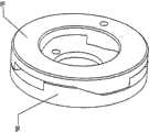
图11为图1变速器的固定支撑件透视图;Fig. 11 is a perspective view of a fixed support member of the transmission of Fig. 1;
图12为图1变速器的螺杆件和螺母透视图;Figure 12 is a perspective view of a screw member and a nut of the transmission of Figure 1;
图13为图1变速器的框架支撑件透视简图;Fig. 13 is a schematic perspective view of a frame support member of the transmission of Fig. 1;
图14为图1变速器的中心滑道局部剖面透视图;Fig. 14 is a partial sectional perspective view of the central slideway of the transmission of Fig. 1;
图15为图1变速器的周边滑道透视图;Figure 15 is a perspective view of the peripheral slideways of the transmission of Figure 1;
图16为图1变速器的连接组件透视图;Figure 16 is a perspective view of the connection assembly of the transmission of Figure 1;
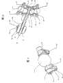
图17为图1变速器的分离机构组件透视图;Fig. 17 is a perspective view of the separation mechanism assembly of the transmission of Fig. 1;
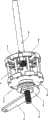
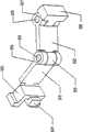
图18为图1变速器的操纵把手换挡装置透视图;Fig. 18 is a perspective view of the operating handle shifting device of the transmission of Fig. 1;
图19为图1变速器的可选实施方案剖面侧视图;Figure 19 is a sectional side view of an alternative embodiment of the transmission of Figure 1;
图20为图1变速器的另一个可选实施方案剖面侧视图;Figure 20 is a sectional side view of another alternative embodiment of the transmission in Figure 1;
图21为图20变速器的透视图,示出一扭力拉条;Figure 21 is a perspective view of the transmission of Figure 20, showing a torsion brace;
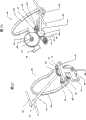
图22为图1变速器的可选分离机构透视图;Figure 22 is a perspective view of an optional release mechanism of the transmission of Figure 1;
图23为图22的可选分离机构另一个透视图;Fig. 23 is another perspective view of the alternative separation mechanism of Fig. 22;
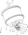
图24为图20变速器轴向力产生装置的可选实施方案组件视图;Fig. 24 is a component view of an optional embodiment of the axial force generating device of the transmission in Fig. 20;
图25为图24轴向力产生装置的花键和凹槽剖视简图;Fig. 25 is a schematic sectional view of the spline and the groove of the axial force generating device of Fig. 24;
图26为图1变速器的可选分离机构透视图;Figure 26 is a perspective view of an optional release mechanism of the transmission of Figure 1;
图27为图26的可选分离机构透视图。FIG. 27 is a perspective view of the alternative separation mechanism of FIG. 26. FIG.
具体实施方式Detailed ways
现在将参照这些附图对本发明的实施方案进行说明,在这些附图中相同的编号表示相同的元件。本文说明中所使用的术语不能简单地按照任何限定性或限制的方式进行解释,因为它是结合本发明特定具体实施方案的详细说明使用的。另外,本发明的实施方案可以包括几个新颖的特征,其中任何单个特征都不单独对其所要求的属性负责或者对实施本文所述的发明是必不可少的。Embodiments of the invention will now be described with reference to the drawings in which like numerals refer to like elements. The terminology used in the description herein is not to be construed simply in any limiting or restrictive manner, as it is used in connection with the detailed description of certain specific embodiments of the invention. Additionally, embodiments of the invention may contain several novel features, no single one of which is solely responsible for its claimed attributes or is essential to practicing the invention described herein.
本文所述的变速器是如在2000年10月24日提出的美国专利申请No.09.695757中所述的一样采用了具有倾斜轴调速器球的型式。主动(输入)盘和从动(输出)盘与调速器球接触。当球在其轴上倾斜时,一个圆盘上的滚动接触点朝着球的顶点或轴运动,在直径缩小的圆周处接触该球,而另一个圆盘上的滚动接触点朝着球的赤道运动,因此在直径增大的圆周处接触圆盘。如果球轴反向倾斜,则这些圆盘相应地倒转。这样,只是倾斜调速器球的轴便可在大范围内改变主动盘的转速与从动盘的转速的比值或者传动比。The variator described herein is of the type with inclined shaft governor balls as described in US Patent Application No. 09.695757 filed October 24,2000. The driving (input) and driven (output) discs are in contact with the governor balls. As the ball tilts on its axis, the rolling contact point on one disk moves toward the apex or axis of the ball, contacting the ball at a reduced diameter circumference, while the rolling contact point on the other disk moves toward the ball's apex or axis. The equator moves and thus touches the disk at a circumference of increasing diameter. If the axis of the ball is tilted in the opposite direction, the discs are inverted accordingly. In this way, the ratio of the rotational speed of the driving disc to the rotational speed of the driven disc, or the transmission ratio, can be changed over a wide range by simply tilting the shaft of the governor ball.
参照变速器实施方案的纵轴,主动盘和从动盘可从调速器球径向向外设置,并且惰轮型通常为圆柱形的支撑部件从调速器球向内径向设置,从而使每个球与内部支撑部件和外部圆盘三点接触。主动盘、从动盘和支撑部件都可以绕着同一纵轴转动。主动盘和从动盘可以形成为简单的圆盘或可以根据所要求的输入和输出的结构而为凹形、凸形、圆柱形或任何其它形状。圆盘接合调速器球的滚动接触面根据施加的扭矩和效率要求可以是平坦的、凹形的、凸形的或其它形状。With reference to the longitudinal axis of the variator embodiment, the drive and driven discs may be positioned radially outward from the governor balls, and an idler-type generally cylindrical support member is positioned radially inward from the governor balls so that each A ball is in three-point contact with the inner support member and the outer disc. The driving disc, the driven disc and the supporting part can all rotate around the same longitudinal axis. The driving and driven discs can be formed as simple circular discs or can be concave, convex, cylindrical or any other shape depending on the desired input and output configuration. The rolling contact surface where the disc engages the governor ball can be flat, concave, convex or other shape depending on the applied torque and efficiency requirements.
参照图1和2,该图披露一个连续可变变速器100的实施方案。该变速器100罩在毂套40中,该毂套起到输出盘的作用,并且理想地用在各种用途中,其中包括车辆(例如自行车或摩托车)具有装在从动轮内的变速器的那些用途。在某些实施方案中毂套40可盖上毂盖67。在变速器100的中心有多个调速器1,它们形状可以为球形,并且围绕着变速器100的中心线或转轴在圆周上或多或少等距离或对称地隔开。在所示的实施方案中,采用了八个调速器1。但是,应该指出的是,可以根据变速器100的用途使用更多或更少的调速器1。例如,该变速器可以包括3、4、5、6、7、8、9、10、11、12、13、14、15或更多的调速器。设置多于3、4或5个调速器可以达到某些优点,例如包括广泛分布施加在各个调速器1及其与变速器100其它部件接触点上的力。在扭矩低传动比高用途中的某些实施方案可以使用少量大型的调速器1,而在扭矩高变速器传动比也高用途中的某些实施方案可以使用许多大型的调速器1。在扭矩高传动比低用途中的其它实施方案可以使用许多小型的调速器1。最后,在扭矩低传动比也低用途中的某些实施方案可以使用少量小型的调速器1。Referring to FIGS. 1 and 2, an embodiment of a continuously
轴3插入穿过每个调速器1中心的孔,以限定每个调速器1的转轴。轴3通常为细长的轴,调速器1绕着该轴转动,轴3有两个端部,它们伸出贯穿调速器孔的每个端部。某些实施方案具有圆柱形轴3,但是可以采用任何形状。调速器1安装成可以绕着轴3自由转动。在图1中,显示的调速器1转轴沿着大致水平方向(即平行于变速器100的主轴)。A
图1、4和5可以用来说明调速器1的轴如何在操作中可能倾斜而使变速器100换挡。图4描述了换到低传动比或低挡的变速器100,而图5则说明换到高传动比或高挡的变速器100。现在还参照图9和10,多个轴支撑件2在从贯穿调速器1的孔伸出的轴3每个端部附近连接到轴3上,并且从那些连接点朝着变速器100的轴径向向内延伸。在一个实施方案中,每个轴支撑件2具有安装其中一根轴3的一个端部的通孔。轴3最好贯穿超出轴支撑件2,使之具有露出的端部。在所示的实施方案中,轴3最好具有共轴滑动设置在轴3露出端部上的轴滚轮(spindle roller)4。这些轴滚轮4通常为圆柱形轮,轴向固定在轴支撑件2外面远处的轴3上,而且自由地绕着轴3转动。还参照图11,轴滚轮4和轴3的端部装在切入一对固定支撑件5a、5b中的凹槽6中。Figures 1, 4 and 5 may be used to illustrate how the shaft of the
参照图4、5和11,固定支撑件5a、5b通常为平行圆盘形状,它们在动力调节器1的每一侧围绕变速器的轴线环形设置。在轴支撑件2从变速器100的轴径向移出使轴3倾斜而改变调速器1的转轴时,每个轴滚轮4装进切入固定支撑件5a、5b之一的凹槽6并沿着该凹槽移动。调速器1可能施加到轴3上的任何径向力(不是旋转力而是横轴向力)被轴3、轴滚轮4和固定支撑件5a、5b中凹槽6的侧面81所吸收。固定支撑件5a、5b装在沿变速器100的轴设置的一对分轴98、99上。分轴98、99通常为细长的圆柱体,它们限定出变速器100轴向长度相当大的部分,因而可用来将变速器100连接在使用它的物体上。每根分轴98、99具有变速器100中间附近的内端和伸出变速器100内壳体的外端。这些分轴98、99最好中空以便安装其它可起作用的任选部件。固定支撑件5a、5b各有一孔82,分轴98、99插入穿过该孔,并且刚性连接以防止在分轴98、99和固定支撑件5a、5b之间出现任何相对运动。固定支撑件5a、5b最好刚性连接在离变速器100中心最近的分轴98、99端部上。固定支撑螺母90可以拧在分轴99上并且通过固定支撑件5a、5b的相应螺纹紧固在固定支撑件5b上。上面所指的固定支撑件5a、5b中的凹槽6从固定支撑件5a、5b的外圆周朝着分轴98、99径向向内延伸。在大多数实施方案中,凹槽6的凹槽侧面81基本上平行以使轴滚轮4可在变速器100换挡时沿着凹槽侧面81上下滚动。另外,在某些实施方案中,凹槽6的深度在固定支撑件5a、5b的周边9基本上恒定,但是这些凹槽6的深度在离分轴98、99较近的点7处变得浅些,以便在它们倾斜时与轴3端部运动的弧形相对应,并且增加固定支撑件5a、5b的强度。在改变调速器1的转轴将变速器100换到较低或较高的传动比时,位于单根轴3相对端的成对轴滚轮4的每一对均沿着它们的相应凹槽6反向运动。Referring to Figures 4, 5 and 11, the fixed
参照图9和11,固定支撑轮30可以用固定支撑轮销31或者通过任何其它连接方法连接在轴支撑件2上。固定支撑轮30共轴滑动地安装在固定支撑轮销31上并用标准紧固件例如环夹固定。在某些实施方案中,一个固定支撑轮30设置在轴2的每一侧要留有足够的间隙,以便使固定支撑轮30在变速器100换挡时能够在固定支撑件5a、5b的凹面84上径向滚动。在某些实施方案中,这些凹面84与调速器1的中心同心。Referring to Figures 9 and 11, the fixed
参照图2、3和11,多个细长衬垫8围绕着变速器的轴径向分布,并且与该轴通常共轴延伸。这些细长衬垫8把固定支撑件5a相互连接起来,从而提高了变速器100内部结构的强度和刚度。衬垫8的取向通常是相互平行,而在有些实施方案中,每个衬垫从靠近外周边的一个固定支撑件5a的点处延伸至另一个固定支撑件5b上的相应点。衬垫8还可以精确地固定在固定支撑件5a、5b之间的距离内,使固定支撑件5a、5b的凹槽6对准,确保固定支撑件5a、5b平行,并且形成在分轴98、99之间的连接。在一个实施方案中,衬垫8被压穿过固定支撑件5a、5b上的衬垫孔46。虽然示出有八个衬垫8,但是可以使用或多或少的衬垫8。在某些实施方案中,衬垫8设在两个调速器1之间。Referring to Figures 2, 3 and 11, a plurality of
参照图1、3和13,在某些实施方案中,固定支撑件5a刚性连接在围绕着分轴98共轴设置的固定支撑套筒42上,或者以其它方式刚性连接在分轴98上或者制成该分轴98的一个整体部分。固定套筒42贯穿毂套40的壁并且连接在框架支撑件15上。在有些实施方案中,框架支撑件15共轴装在固定套筒42上,并且刚性连接在该固定套筒42上。该框架支撑件15在有些实施方案中使用扭矩杆件(torque lever)43来保持固定套筒42的固定位置。扭矩杆件43通过框架支撑件15将固定套筒42以及固定部件的剩余部分机械连接在要装变速器100的物体的固定支撑部件上,从而为变速器100提供转动稳定性。扭矩螺母(torque nut)44拧到固定套筒42的外面以使扭矩杆件43保持在与框架支撑件15接合的位置。在某些实施方案中,框架支撑件15不是圆柱形,以便直接(in a positive manner)接合扭矩杆件43,从而防止固定套筒42转动。1, 3 and 13, in some embodiments, the fixed
例如,该框架支撑件15可以是方形件,厚度等于扭矩杆件43厚度,侧面大于固定套筒,而孔则从其中心切出,从而使该方形件可以装配在固定套筒42上,然后进行刚性连接。另外,扭矩杆件43可以是杠杆臂,厚度等于框架支撑件15的厚度,第一端部靠近框架支撑件15而第二端部与第一端部相对。在有些实施方案中,扭矩杆件43还具有一个穿过其端部之一的孔,但是该孔是方形,并且是比框架支撑件15稍大的方形,因此扭矩杆件43可以在框架支撑件15上滑动,从而导致框架支撑件15和扭矩杆件43转动接合。另外,扭矩杆件43的杠杆件臂如此定位,要使第二端部延伸至连接在自行车、汽车、拖拉机或其它使用变速器100之处的框架上,以此通过框架支撑件15和固定套筒42克服由变速器100施加的任何扭矩。固定支撑轴承48共轴装配在固定套筒42周围,而且轴向位于毂套40的外边缘和扭矩杆件43之间。该固定支撑轴承48支撑毂套40,使毂套40能够相对于固定支撑套筒42转动。For example, the
参照图1和10,在有些实施方案中,通过转动设置在中空分轴98中的杆件10手工作动换挡。在有些实施方案中,有一组外螺纹的蜗杆件11连接在处于变速器100中心杆件10的端部上,而该杆件10的另一个端部轴向延伸至变速器100的外面,并且具有外螺纹,固定在其外表面。在一个实施方案中,蜗杆件11拧入具有相配螺纹的共轴套筒19中,从而在杆件10和蜗杆件11转动时,该套筒19就轴向运动。套筒19通常为中空圆柱体,共轴装配在蜗杆件11和杆件10周围,并且具有两个端部,一个端部靠近固定支撑件5a,而另一个靠近固定支撑件5b。该套筒19每个端部固定在平台13、14上。这两个平台13、14每个通常都是圆环形状,其内径大到足以能装配并连接在套筒19上,而且成形为具有两个侧面。第一侧面通常为直面,它通过两组接触轴承17a、17b动态接触和轴向支撑着支撑部件18。每个平台13、14的第二侧面是凸面形状。平台13、14每个都连接在套筒19外面的一个端部上,以便形成围绕套筒19周边的环槽。一个平台13连接在离固定支撑件5a最近的侧面上,而另一个平台14则连接在离固定支撑件5b最近的端部上。平台13、14的凸面起到凸轮的作用,每个都接触并推动多个换挡轮21。为了达到这种凸轮带动的作用,平台13、14最好在它们的周边(离分轴98、99最远)附近过渡成凸形弯曲面97,它可以是也可不是圆弧形。该弯曲面97与换挡轮21接触,致使这些平台13、14轴向运动,换挡轮21沿着平台13、14表面朝着通常径向方向运动,以迫使轴支撑件2从分轴98、99径向出来,或者朝着它们进入,由此改变轴3和相关调速器1转轴的角度。在某些实施方案中,换挡轮21在离变速器100中心线最近的端部装进轴支撑件2上的狭槽中,并靠轮轴22保持就位。Referring to FIGS. 1 and 10 , in some embodiments, shifting is manually performed by turning a
仍然参照图1和10,支撑部件18设置在形成在平台13、14和套筒19之间的沟槽中,因此与平台13、14和套筒19一致运动。在某些实施方案中,支撑部件18通常有一个外径,并且沿着其内径中心通常为圆柱形,在其内径的每个边缘上具有轴承座圈。在其它实施方案中,支撑部件18的外径可以是不均匀的,并且可以是任意形状,例如倾斜的或弯曲的。支撑部件18具有两个侧面,一个侧面靠近其中一个固定支撑件5a,一个侧面靠近另一个固定支撑件5b。该支撑部件18搭在两个接触轴承17a、17b之间,从而在支撑部件18和套筒19之间形成滚动接触。接触轴承17a、17b共轴位于套筒19周围,而套筒19与平台13、14相交,从而使支撑部件18能够绕着变速器100的轴自由转动。该套筒19由蜗杆件11和杆件10轴向支撑,因此通过这种结构,该套筒19能够在蜗杆件11使它定位时轴向滑动。当变速器100换挡时,套筒19轴向运动,而且动态或静态连接在套筒上的所有轴承17a、17b、支撑部件18和平台13、14都以相应的方式轴向运动。Still referring to FIGS. 1 and 10 , the
在某些实施方案中,杆件10在其与蜗杆件11相对的端部通过杆件螺母51和杆件凸缘52连接在换挡管50上。换挡管50通常为管形,有一端是开口,另一端基本封闭。换挡管50的开口端其直径适于装在从变速器100中心向外轴向延伸的分轴98的端部上。换挡管50基本封闭的端部具有一个贯穿它的小孔,从而使与蜗杆件11相对的杆件10端部能在换挡管50置于分轴98的外面上时穿过该小孔。然后,换挡管50基本封闭的端部可分别通过紧固在换挡管50外面的杆件螺母51和又紧固在换挡管50基本封闭的端部里面的杆件凸缘52固定在轴向位置中。在有些实施方案中,换挡管50可通过连接在换挡管50外面上的缆索53转动。在这些实施方案中,缆索53通过缆索夹54和缆索螺钉56连接在换挡管50上,然后缠绕在换挡管50上,从而当拉力施加在该缆索53上时,围绕换挡管50的轴中心产生一个力矩,因而使之转动。或者可通过任何其它机构,例如杆件、手工转动、伺服电机或其它设法使杆件10转动的方法造成换挡管50的转动。在某些实施方案中,当拉动缆索53而使换挡管50在分轴98上顺时针转动时,蜗杆件11也顺时针转动,以致将套筒19、支撑部件18和平台13、14轴向拉向换挡管50,并使变速器100换向低传动比。如图3所示,连接在蜗杆件11端部的蜗杆件弹簧55可以是能够产生压力和转动力的锥形盘簧,它设置在固定支撑件5b和平台14之间,并且阻挡变速器100换挡。蜗杆件弹簧55设计成偏移换挡管50转动,以便使变速器100在有些实施方案中换向低传动比而在另一些实施方案中换向高传动比。In certain embodiments, the end of the
参照图1、10和11,平台13、14的轴向运动限定了变速器100的换挡范围。轴向运动被与平台13、14接触的固定支撑件5a、5b上的内表面85所限制。在极高的传动比时,平台14接触固定支撑件5a、5b之一的内表面85,而在极低的传动比时,平台13接触固定支撑件5a、5b中另一个的内表面85。在许多实施方案中,平台13、14的凸形半径曲率在作用上取决于从调速器1的中心到轮21中心的距离,轮21的半径、可操作连接在每个调速器1上的两个轮21之间的距离以及调速器1轴的倾角。Referring to FIGS. 1 , 10 and 11 , the axial movement of the
尽管披露了左旋螺纹螺杆件11,但是可以使用右旋螺纹螺杆件11、相应的右旋缠绕的换挡管50以及刚才所述可用来支持支撑部件18和平台13、14横向运动的任何其它组合部件。另外,换挡管50可以具有内螺纹,与分轴98外面的外螺纹啮合。通过增加这种螺纹啮合,换挡管50在它绕着分轴98转动时将轴向运动,从而使得杆件10也轴向运动。这样可以用来增强由蜗杆件11造成的套筒19轴向运动,以便加强蜗杆件11转动的效果,从而更加迅速地变换齿轮速比,或者降低蜗杆件11转动的效果,以便减缓换挡过程和使变速器100调节得更加精确。Although a left-handed threaded
参照图10和18,使用可共轴设在固定管上的旋转操纵把手132、操纵杆件130或其它一些结构件来实现手动换挡。在某些实施方案中,缆索53的端部连接在固定在旋转操纵把手132上的缆索止动件133上。在有些实施方案中,变速器100和锥形弹簧55的内力往往导致变速器偏移换向较低的传动比。当用户转动旋转操纵把手132时,可以围绕着旋转操纵把手132沿着凹槽缠绕的缆索53根据缆索53的转动方向缠绕或退绕,同时换挡管50转动,把变速器100换向较高的传动比。一组棘轮齿134可以呈圆周形式设在旋转操纵把手132的两个侧面之一上,以便与棘轮管(ratcheted tube)135的第一侧面上的配套棘轮齿组啮合,从而防止旋转操纵把手132反向转动。能够支承调节螺杆提供可变夹紧力的管夹136将棘轮管132固定在操纵柄130上。当反向换挡时,旋转操纵把手132被迫反向朝着较低传动比转动,引起管夹136与旋转操纵把手132一致转动。在与棘轮齿134相对的侧面贴近棘轮管135设置的操纵柄管(handlebar tube)137通过管夹138刚性夹紧在操纵柄130上,从而防止棘轮管135与棘轮齿134分离。不能转动的操纵把手131固定在操纵柄130上,并且设置贴近旋转操纵把手132,以防止旋转操纵把手132轴向运动和防止棘轮齿134与棘轮管135分离。Referring to Figures 10 and 18, manual gear shifting is accomplished using a
现在参照图1、9和11所示的实施方案,一个或多个固定支撑滚轮30可通过插入穿过每个轴支撑件2上的孔的滚轮销31连接在每个轴支撑件2上。这些滚轮销31具有适当的尺寸和结构,从而使固定支撑滚轮30能够在每个滚轮销31上自由转动。固定支撑滚轮30沿着面对调速器1的固定支撑件5a、5b侧面上的弯曲凹面84滚动。固定支撑滚轮30提供轴向支撑,以防止轴支撑件2轴向运动,并且还确保轴2在变速器100换挡时容易倾斜。Referring now to the embodiment shown in FIGS. 1 , 9 and 11 , one or more
参照图1、12、14和17,位于固定支撑件5b附近的三个辐条式主动盘34部分封装,但是通常不会接触固定支撑件5b。主动盘34可以具有两根或多根辐条或者可以是实心盘。这些辐条降低了重量,并且在使用它们的实施方案中有助于变速器100的装配,但是也可以采用实心盘。主动盘34具有两个侧面,即与调速器1接触的第一侧面和面对第一侧面对面的第二侧面。主动盘34通常是环形盘,它以其内径共轴装在一组内螺纹或螺母37上,并从其中径向延伸。如果采用的毂套40为封装调速器1和主动盘34的类型,并且与毂盖67接合,主动盘34的外径则设计成配装在毂套40内。主动盘34沿着主动盘34第一侧面的唇部上的圆周支承面可转动连接在调速器1上。如上所述,主动盘34的一些实施方案在其中心处具有一组内螺纹37或螺母37,并且该螺母37拧在螺杆件35上,从而使主动盘34与螺杆件35啮合。该螺杆件35刚性连接在一组中心螺杆件滑道(screw ramp)90上,该螺杆件滑道通常是一组共轴设置在分轴99上的环形盘上的凸面。这些中心螺杆件滑道90由一组中心主动轴滑道91驱动,它们同样形成在通常为环形的盘上。中心驱动滑道91和中心螺杆滑道90的滑道面可以是线性的,但是也可以是任何其它形状,并且相互可操作接触。共轴且刚性连接在主动轴69上的中心主动轴滑道91向中心螺杆件滑道90施加扭矩和轴向力,这些扭矩和轴向力然后传递给主动盘34。设置在中心主动轴滑道91和中心螺杆件滑道90之间的中心驱动受拉杆件92产生转动力和/或压力,以确保中心滑道90、91相互接触。Referring to Figures 1, 12, 14 and 17, the three spoke-
仍然参照图1、12、14和17,能够轴向运动的螺杆件35可以随着环形止推轴承73接触面对调速器1的螺杆件35侧面上的座圈偏移而轴向移动离开调速器1。共轴设置在分轴99上的环形止推垫圈72接触止推轴承73,并且可被销12推动,该销12贯穿分轴99上的狭槽。能够产生压力的受压杆件95在第一端部设置在中空分轴99的孔中。可为弹簧的受压杆件95在一个端部接触销12,而在第二端部接触杆件10。当杆件10朝着较高传动比换挡并且轴向运动时,便接触受压杆件95,将它按压在销12上。一旦传动比朝向高挡超过1∶1传动比并且主动盘34转动的比毂套40要慢,则变速器100的内力便偏移支撑部件18,使朝向高传动比位置移动。这种偏移轴向推动螺杆件35,从而使它与螺母37分离,并且不再向主动盘34施加轴向力或扭矩,或者减小螺杆件35施加在螺母37上的力。在这种情况下,由周边滑道61施加在主动盘34上的轴向力百分比便得到增加。应该注意的是,一旦支撑部件18朝着低挡超过1∶1传动比的位置并且毂套40转动的比主动盘34要慢,则变速器100的内力仍然朝着低挡偏移支撑部件18。由于在换到低挡时转速下降并且扭矩增加,所以这个有利的偏移有助于换挡。Still referring to FIGS. 1 , 12 , 14 and 17 , the axially
仍然参照图1、12、14和17,主动轴69为具有两个端部并共轴设置在分轴99外面通常为管状的套筒,该主动轴69一个端部具有与其连接的上述中心主动轴滑道91,而相对端部则背对主动盘34。支承盘60通常为径向圆盘,它共轴设在主动轴69上,向外径向延伸至通常等于主动盘34的半径距离。支承盘60设在主动轴69上靠近主动盘34的位置,但离得足够远,使有空间用于一组周边滑道61、相关的滑道轴承62和轴承座圈64,所有这些部件都位于主动盘34和支承盘67之间。在某些实施方案中,多个周边滑道61可以是凹形的,并且刚性连接在面对主动盘34侧面的支承盘60上。换句话说,这些周边滑道61根据变速器100的用途可以是凸形的或线性的。另一方面,轴承座圈64可以被第二组周边滑道97代替,这些周边滑道97也可以是线性的、凸形的或凹形的,并且刚性连接在面对支承盘60侧面的主动盘34上。这些滑道轴承62通常是多个轴承,在数量上与周边滑道61相配。多个滑道轴承62的每一个位于一个周边滑道61和轴承座圈64之间,并通过由滑道61还有轴承罩63施加的压力而保持就位。轴承罩63是一环形圈,它与分轴99共轴,并且轴向设置在凹形滑道61和凸形滑道64之间。轴承罩63具有比较大的内径,致使该轴承罩63的径向厚度只是稍微大于滑道轴承62的直径,以便安装滑道轴承62。每个滑道轴承62装进形成在轴承罩63径向厚度上的孔中,并且这些孔伴随着前面所述的压力使滑道轴承62保持就位。轴承罩63可以通过比轴承罩63内径稍微小的支承盖60或主动盘34的凸缘引导到位。Still referring to Fig. 1, 12, 14 and 17, the
参照图1、6、7、8和15,描述一个实施方案的支承盘60,周边滑道61和滑道轴承62。特别参照图6,该示意图示出接触凹形周边滑道61的滑道轴承62和第二凸形周边滑道97。特别参照图7,该示意图示出在不同扭矩或传动比时图6滑道轴承62、凹形周边滑道61和第二凸形周边滑道97。在图7所示滑道轴承62在周边滑道61上的位置产生的轴向力比在图6所示这些滑道轴承62在周边滑道61上的位置要小。特别参照图8,示出接触凸形周边滑道61的滑道轴承62以及在那些相应滑道上处于基本中心位置的凹形第二周边滑道97。应该注意的是,周边滑道61、97的曲线变化会改变在不同传动比时施加在动力调节器1上的轴向力值,由此使不同齿轮速比的效率和扭矩变化达到最大限度。根据变速器100的用途,可以采用弯曲或线性周边滑道61、97的许多组合形式。为了简化操作和降低成本,在一些用途中,可以省去一组周边滑道,例如第二组周边滑道97,然后用轴承座圈64代替。为了进一步降低成本,这组周边滑道61可以具有线性倾斜度。Referring to Figures 1, 6, 7, 8 and 15, one embodiment of the
参照图1,具有两个端部的盘簧65共轴缠绕在主动轴69上,并且一个端部连接在支承盘60上,而另一个端部则连接在主动盘34上。盘簧65具有作用力,使主动盘34与调速器1保持接触,并且沿着周边滑道61向上偏移滑道轴承62。盘簧65设计成将需要操作的轴向空间缩小到最低程度,并在某些实施方案中,盘簧65的横断面为矩形,其径向长度大于轴向长度。Referring to FIG. 1 , a
参照图1,支承盘60最好接触面向凹形滑道61对面的支承盘60侧面上的外部毂盖轴承66。外部毂盖轴承66可以是径向设置在变速器100中心线外面但要与其共轴的环形滚柱轴承组66。外部毂盖轴承66径向设置在可以与毂盖67和支承盘60接触的位置,以便使它们能够彼此之间相对运动。毂盖67通常为中心有孔的圆盘形状,以便装在主动轴69上,并且具有一外径,这样将它装在毂盖40内。毂盖的内径与设置在毂盖67和主动轴69之间的内部毂盖轴承96接合,并且保持毂盖67和主动轴69彼此之间相对径向和轴向对准。毂盖67在其外径的边缘可制螺纹,以便毂盖67可以拧到毂套40内,以封装大部分变速器100。链轮或滑轮38或其它传动系连接装置,例如齿轮装置可以刚性连接在旋转主动轴69上,以达到输入转动。主动轴69通过锥形轴承70使其保持在围绕分轴99的共轴位置上。锥形轴承70为环形轴承,围绕分轴99共轴安装,并能在主动轴69和分轴99之间滚动接触。锥形轴承70可以通过拧到分轴99上的锥形螺母71或者通过任何其它紧固方法固定在其轴向位置。Referring to FIG. 1, the
在某些实施方案操作中,来自链轮或滑轮38的输入转动被传递给主动轴69,该主动轴69又使支承盘60和多个周边滑道61转动,从而使得滑道轴承62沿着周边滑道61向上滚动,而将主动盘34压在调速器1上。滑道轴承62在它们楔入周边滑道61和凸形滑道64之间并在两者之间传递能量时同样把转动能量传递给主动盘34。转动能量从主动盘34传递给调速器1,它又使毂套40转动,从而为变速器100提供输出转动和扭矩。In certain embodiment operations, the input rotation from the sprocket or
参照图16,卡锁115刚性连接在面对支承盘60的主动盘34的侧面上,并且接合刚性连接在钩杆件(hook lever)113两个端部的第一个上。卡锁115开口下面的接合面积大于钩114的宽度,并且提供特别大的空间,以便钩114能在主动盘34和支承盘60彼此之间相对运动时在卡锁114的限定范围内相对于轴径向运动。钩杆件113通常是用于钩114的纵向支撑部件,并在其第二端部钩杆件113有一整体钩铰链116,它通过第一铰链销111与中间铰链119接合。中间铰链119与主动盘杆件112的第一端部成一整体,是具有两个端部通常细长的支撑部件。在其第二端部,该主动盘杆件112具有一整体主动盘铰链117,该铰链117通过使用第二铰链销118接合铰链支柱110。该铰链支柱110通常是一底座,用来支撑钩114、钩杆件113、钩铰链116、第一铰链销111、中间铰链119、主动盘杆件112,第二铰链销118和主动盘铰链117,并且它刚性连接在面对主动盘34侧面上的支承盘60上。当卡锁73和钩72接合时,可防止滑道轴承62滚动到在周边滑道61上没有向主动盘34提供正确量轴向力的区域。这就确保了由周边滑道61施加在滑道轴承62上的所有转动力传递给主动盘34。Referring to FIG. 16 , the
参照图1和17,该图描述了变速器100一个实施方案的分离机构,用来分离主动盘34与调速器1,以便滑行。在向变速器100输入转动中断的时候,链轮或滑轮38停止转动,但是毂套40和调速器1会继续转动。这使主动盘34转动,致使主动盘34孔中的内螺纹组37缠绕到外螺纹螺杆件35上,从而轴向移动主动盘34离开调速器1,直到主动盘34不再接触调速器1为止。刚性连接在面对支承盘60侧面主动盘34上的齿条126具有齿,这些齿在主动盘34缠绕到螺杆件35上并与动力调节器1分离时接合齿轮124并且使之转动。齿轮124的中心有一孔,穿过该孔设置一齿轮轴套121,以使齿轮124转动。共轴连接在齿轮轴套121上的夹子125把齿轮124固定就位,不过可以使用任何固定装置。共轴设置在中心主动轴滑道91上并紧固其上的预加载器(preloader)沿着从变速器100中心径向向外的方向延伸。由在弯曲时能恢复到其原始形状的弹性材料制成的预加载器120具有第一端部128和第二端部127。该预加载器128的第一端部贯穿齿轮轴套121并终止在轴承罩63。该预加载器128的第一端部沿着滑道61向上偏移轴承罩63和滑道轴承62,以确保滑道轴承62和滑道61之间的接触,并且还把齿轮124偏移在齿条126上。卡爪123啮合齿轮124,并在一个实施方案中啮合与齿条126基本相对侧面的齿轮124。卡爪123具有一孔,穿过该孔是卡爪轴套122,致使卡爪123能够转动。夹子125或其它紧固装置将卡爪123固定在卡爪轴套121上。卡爪弹簧122偏移卡爪123的转动,以啮合齿轮124,因而防止齿轮124在主动盘34缠绕到螺杆件35上时使其反向转动。卡爪轴套121设置在预加载器127的第二端部,与主动轴69一致转动。Referring to Figures 1 and 17, this figure depicts a disengagement mechanism of an embodiment of the
再参照图1,与主动轴69共轴并围绕着它设置的盘簧65轴向位于支承盘60和主动盘34之间,并且通过销或其它紧固件(未示出)一个端部连接在支承盘60上,而另一个端部连接在主动盘34上。在某些实施方案中,盘簧65代替了现有技术的盘簧,以便提供更大的作用力并且占据更少的轴向空间,从而减小变速器100的外形尺寸。在有些实施方案中,盘簧65由矩形弹簧钢线材生产,其径向长度或高度大于其轴向长度或宽度。在变速器100的运行过程中,盘簧65确保了调速器1和主动盘34之间的接触。但是,一旦主动盘34已经脱离调速器1,便可防止盘簧65缠绕主动盘34,致使齿轮124和卡爪123啮合而使主动盘34再次接触调速器1。当输入链轮、齿轮或滑轮38重新开始转动时,卡爪123也转动,从而使齿轮124转动,因此使得主动盘34转动,并且由于盘簧65产生的转动力而从螺杆件35退绕。卡爪123和齿轮124之间的相对运动是由以下情况产生的,即因为预加载器128的第一端部连接在轴承罩63,所以预加载器128的第一端部以预加载器127的第二端部大约一半的速度转动。另外,因为滑道轴承62正在支承盘60的周边滑道61上滚动,所以轴承罩63将以支承盘60一半的速度转动。Referring again to FIG. 1 , a
现在参照图19,该图披露了图1变速器100的可选实施方案。在该实施方案中,输出盘201代替了图1所示变速器100的毂套40。与主动盘34类似的输出盘201接触调速器1,并且通过它转动。输出盘201由接触输出盘201和固定外壳盖204的输出盘轴承202支撑。该外壳盖204用外壳螺栓205或任何其它紧固件刚性连接在固定外壳203上。固定外壳203可以连接在不运动物体,例如框架或连接在它所使用的机器上。齿轮、链轮或滑轮206共轴刚性连接在外壳盖204和固定外壳203外面的输出盘201上。但是可以使用任何其它类型的输出装置,例如齿轮。可以增加扭力拉条207,它将分轴98刚性连接在外壳盖204上,作为附加支撑。Referring now to FIG. 19 , an alternative embodiment of the
现在参照图20和21,这些图披露了图1变速器100的可选实施方案。固定支撑座圈302添加在背对调速器1的固定支撑件5a的侧面上,并且与固定支撑轴承301和旋转毂套座圈303接合,以保持固定支撑件5a相对于旋转毂套40正确对准。扭力拉条304刚性连接在固定支撑件301上,然后可以刚性连接在外部固定部件上,以防止固定支撑件5a、5b在变速器300的运行期间转动。主动轴轴承306设置在主动轴69面对调速器1的端部,并且接合形成在主动轴69同一端部的主动轴座圈307和形成在分轴99径向凸起部分上的分轴座圈305,以便向主动轴69提供附加支撑,并且使主动轴69相对于固定支撑件5a、5b正确定位。在利用图20所示结构的实施方案中,在毂盖67的内径和主动轴69上与其相邻的位置之间采用了动态密封件(未示出),因为所述两个部件经常以不同的速度转动。密封件可以用来最大限度地减少进入旋转轮毂40内的灰尘和碎屑量。Referring now to FIGS. 20 and 21 , these figures disclose an alternative embodiment of the
现在参照图22和23,该图披露了图1变速器100的可选分离机构400。齿轮402共轴设置在轮轴套408上,并用夹子413或其它紧固件固定就位,以便使它能够转动。轮轴套408共轴设置在具有第一端部和第二端部(这两个端部在图22和23中没有单独示出)的预加载器405的第一端部上。预加载器405环绕中心主动轴滑道91弹性夹紧。该预加载器405的第一端部延伸到轴承罩63,沿着周边滑道61向上偏移轴承罩63。另外,设置在轮轴套408上的还有一杠杆件401,它绕着轮轴套408转动,并且支撑齿轮卡爪411和小齿轮卡爪409。齿轮卡爪411啮合齿轮402,以控制其转动,并且设置在压入杠杆件401孔的齿轮轴套414上面。齿轮卡爪弹簧412将齿轮卡爪411偏压在齿轮402上。与杠杆件401上齿轮卡爪411基本相对设置的小齿轮卡爪409共轴设置在装到杠杆件401另一个孔中的小齿轮卡爪轴套415上,而使小齿轮卡爪409旋转运动。小齿轮卡爪弹簧410将小齿轮卡爪409偏移在小齿轮403上。Referring now to FIGS. 22 and 23 , there is disclosed an
现在参照图1、22和23,小齿轮403中心有一孔,并且共轴设置在棒式杠(rod lever)杆件404的两个端部的第一个上。棒式杠杆件是一种细长的杆件,它在滑行期间啮合小齿轮卡爪409,直到链轮、滑轮或齿轮38重新开始输入转动为止。在支承盘60转动时,固定在支承盘60上的支承盘销406接触棒式杠杆件404的第二端部,因而将棒式杠杆件404按压在与主动盘34刚性连接的主动盘销407上。这种动作迫使棒式杠杆件404的第一端部摆动离开齿轮402,从而使小齿轮403暂时脱离齿轮402,使齿轮402转动起来。杆件钩401连接在杠杆件401上,并且接触主动盘34上的卡锁(未示出),因此在盘簧65偏移主动盘34退绕并接触调速器1时被推回。在链轮、滑轮或齿轮38的输入转动中断和调速器1继续旋转期间,主动盘34缠绕到螺杆件35上并且与调速器1分离。在主动盘34转动时,主动盘销407与棒式杠杆件404分离,然后小齿轮403摆动与齿轮402接触,从而防止主动盘34重新啮合调速器1。Referring now to Figures 1, 22 and 23, the
参照图24和25,该图披露了图20变速器300的一套可选轴向力产生装置500的组件。当被输入链轮、齿轮或滑轮38转动时,花键主动轴(splined drive shaft)501转动支承盘60,在其孔中可有凹槽505,以安装和啮合花键主动轴501的花键506。中心主动轴滑道508刚性连接在支承盘60或花键主动轴501上,并转动中心螺杆件滑道507,两者都具有通过花键主动轴501花键506的孔。中心受拉杆件92(图1所示)设置在中心主动轴滑道508和中心螺杆件滑道507之间。具有凹槽端部和支承端部的沟纹螺杆件(grooved screw)502按中心螺杆件滑道90转动,并在其支承端具有凹槽505,这些凹槽比花键主动轴501上的花键506要宽,以致在花键506和凹槽505之间形成间隙。花键506和凹槽505之间的间隙便于在沟纹螺杆件502和/或支承盘60与花键主动轴501之间相对运动。当沟纹螺杆件502没有按中心主动轴滑道508和中心螺杆件滑道507转动时,花键主动轴501的花键506便接触沟纹螺杆件502上的凹槽505并使之转动,因此该沟纹螺杆件502也转动起来。环形螺杆件轴承504接触沟纹螺杆件502支承端上的座圈,并定位,以支撑相对于分轴99轴线的花键主动轴501和沟纹螺杆件502。沟纹螺杆件502的孔稍微大于花键主动轴501的外径,从而使得沟纹螺杆件502能够轴向和旋转相对运动。螺杆件锥形座圈504接触并且接合着环形螺杆件轴承503,并有与其轴线垂直的孔,以使销12能够插入。销12接合杆件10,该杆件10可以推动销12并使沟纹螺杆件502轴向运动,使之与螺母37分离,或者减小施加在其上的轴向力。Referring to FIGS. 24 and 25 , there are disclosed components of an optional axial
参照图26,该图披露了图22和23分离装置400的可选分离装置600。对杠杆件401进行了改进,取消了用于安装小齿轮卡爪409和齿轮卡爪411的T形,以使新杠杆件601只有与其连接的齿轮卡爪411。第二杠杆件602具有第一端部和第二端部。小齿轮卡爪409可操作连接在第二杠杆件602的第一端部上。第二杠杆件602具有一第一孔,通过该孔将预加载器405的第一端部插入。第二杠杆件602可转动安装在预加载器405的第一端部上。第二杠杆件602在其第二端部具有一第二孔,通过该孔将预加载器603的第二端部插入。当链轮、齿轮或滑轮38的转动中断时,主动盘34继续向前转动,并且缠绕到螺杆件36上,直到它与调速器1分离为止。预加载器405的第一端部向前转动,致使小齿轮卡爪409接触小齿轮403并使之顺时针转动。这样造成齿轮402逆时针转动,使齿轮卡爪411越过齿轮402的一个或多个齿,将主动盘34固定并防止它从螺杆件36退绕脱落而接触调速器1。当链轮、齿轮或滑轮38的转动重新开始时,预加载器603的第二端部转动,从而接触第二杠杆件602的第二端部,致使小齿轮卡爪409转出小齿轮403而与其分离,从而使主动盘34能够退绕而与调速器1重新啮合。Referring to Figure 26, there is disclosed an alternative separation device 600 to the
现在就本说明应有的地方对本发明的一些具体改进和优点进行描述。应当指出,不是所有这些改进都必须在本发明的所有实施方案中找到。Some specific improvements and advantages of the present invention will now be described where this description is due. It should be noted that not all such modifications are necessarily found in all embodiments of the invention.
参照图1,有些实施方案的现行改进之处包括向主动盘34提供可变轴向力,以适应不同的负载或用途。这可以通过使用多个轴向力发生器来实现。轴向力可以通过相关的中心主动轴滑道91和螺杆件滑道90在螺杆件35和螺母37之间转换到周边滑道61、64产生。即螺杆件35、中心滑道90、91和周边滑道61、64可以共同产生轴向力。另外,在周边滑道61、64的轴向力可以是可变的。这可以通过使用可变斜度和偏角的滑道来实现,滑道包括凹形和凸形滑道。参照图1和图6-8以及前面的详细说明,披露这样一个实施方案,其中固定在支承盘60上的是第一组周边滑道61,它们可以是凹形的,滑道轴承62与其接触。与第一组周边滑道61相对的是第二组周边滑道97,它们连接在可以是凸形的主动盘34上,并且与滑道轴承62接触。使用凹形和凸形滑道接触滑道轴承62便于根据调速器1和支撑部件18的位置调节非线性地增加或降低主动盘34上的轴向负载。Referring to FIG. 1 , some embodiments present improvements include providing variable axial force to drive
某些实施方案的另一项改进之处包括直接啮合(positivelyengaging)支承盘60和主动盘34,使在扭矩传动的某些挡位提供更大的旋转传动和恒定的轴向推力。例如参照如上所述图1所示的实施方案,这可以通过使用钩114和卡锁115的组合来实现,其中钩114连接在轴承罩63上,该轴承罩63将滑道轴承62罩在主动盘34和支承盘60之间,而卡锁115则连接在主动盘34上,该主动盘34在滑道轴承62到达其在滑道面上相应极限位置时与钩114啮合。尽管提供这种结构作为示例,但是应该理解的是,钩114和卡锁115可以连接在上述相对部件上,或者可以采用许多其它机构来达到支承盘60和主动盘34在滑道轴承62极限位置的这种直接啮合。Another improvement in certain embodiments includes positively engaging the
某些实施方案在原先设计方案上的进一步改进之处是主动盘34具有径向辐条(没有单独示出),这降低了重量并有助于变速器100的装配。在某些实施方案中,主动盘34具有三个彼此等距的辐条,使能连同其它部件一道使用钩114和卡锁115。A further improvement of some embodiments over the original design is that the
某些实施方案的另一项改进之处包括使用螺纹35,例如梯形螺纹,用来在主动盘34和支承盘60之间有相对转动运动时使主动盘34轴向运动。参照图1所示的实施方案,外螺纹螺杆件35可以拧到主动盘34孔中的一组内螺纹37即螺母37上。这使得主动盘34能够在主动盘34中断提供输入扭矩时例如在空挡滑行或者滚动时与调速器1分离,并且还便于对调速器1提供或大或小的轴向力。另外,外螺纹螺杆件35还设计成通过一组内螺纹37将轴向力传递给主动盘34。Another refinement of certain embodiments includes the use of
在以往发明某些实施方案的再一个改进之处是一种将变速器换挡至较高或较低传动比的改进方法。还有,参照图1所示的实施方案,该方法可以通过使用螺纹杆件10例如包括左旋螺纹蜗杆件11和相应的右旋螺纹换挡管50即套筒来实现,它通过缆索53或遥控电机或其它遥控装置来遥控操纵。另一方面,左旋螺纹可以用于蜗杆件11和换挡管,或者可以使用无螺纹换挡管50,并在适当时也可以使用其任意组合以相对于换挡管50的转运速率影响变速器100的换挡率。另外,可以采用锥形弹簧55来帮助操作人员保持适当换挡管50的位置。蜗杆件11最好与螺纹套管19相配,以便使支撑部件18轴向对准,从而在蜗杆件11转动时支撑部件18将轴向运动。Yet another improvement in certain embodiments of the prior invention is an improved method of shifting a transmission to a higher or lower gear ratio. Also, with reference to the embodiment shown in FIG. 1, the method may be implemented by using a threaded
在以往发明有些实施方案的另一个改进之处是用于变速器100的脱离机构。该脱离机构使得输入链轮、滑轮或齿轮38能够反向转动,并且通过主动盘34与调速器1分离还使变速器100能空挡滑行。Another improvement over some embodiments of the prior invention is the disengagement mechanism for the
上面的说明详述了本发明的某些实施方案。但是要理解的是,无论上面在文字上是多么详细,但本发明可以用许多方式来实施。还有上述的也是这样,应当指出,在说明本发明的某些特征或方面时使用的特定术语不应该用来暗示该术语在这里被重新定义来限制包括与该术语相关的本发明的方面或特征的任何具体特点。所以,本发明的范围应该根据所附权利要求和其等同方案进行解释。The foregoing description details certain embodiments of the invention. It is to be understood, however, that no matter how detailed the above may appear in writing, the present invention may be practiced in many ways. Also as above, it should be noted that a particular term used in describing certain features or aspects of the present invention should not be used to imply that the term is redefined herein to limit the aspect or aspect of the invention to which the term relates. Any specific characteristic of a feature. Therefore, the scope of the present invention should be interpreted in accordance with the appended claims and their equivalents.
Claims (25)
Translated fromChineseApplications Claiming Priority (2)
| Application Number | Priority Date | Filing Date | Title |
|---|---|---|---|
| US28680301P | 2001-04-26 | 2001-04-26 | |
| US60/286,803 | 2001-04-26 |
Related Parent Applications (1)
| Application Number | Title | Priority Date | Filing Date |
|---|---|---|---|
| CNB028097610ADivisionCN100472101C (en) | 2001-04-26 | 2002-04-25 | continuously variable transmission |
Publications (2)
| Publication Number | Publication Date |
|---|---|
| CN101526127Atrue CN101526127A (en) | 2009-09-09 |
| CN101526127B CN101526127B (en) | 2011-08-17 |
Family
ID=23100215
Family Applications (3)
| Application Number | Title | Priority Date | Filing Date |
|---|---|---|---|
| CN200910006626.2AExpired - Fee RelatedCN101526133B (en) | 2001-04-26 | 2002-04-25 | The ratio adjusting mechanism of continuously variable transmission, speed ratio adjusting method and operation handle gearshift |
| CN2009100066277AExpired - Fee RelatedCN101526127B (en) | 2001-04-26 | 2002-04-25 | A continuously variable transmission and member support, support frame and frame manufacture method |
| CNB028097610AExpired - Fee RelatedCN100472101C (en) | 2001-04-26 | 2002-04-25 | continuously variable transmission |
Family Applications Before (1)
| Application Number | Title | Priority Date | Filing Date |
|---|---|---|---|
| CN200910006626.2AExpired - Fee RelatedCN101526133B (en) | 2001-04-26 | 2002-04-25 | The ratio adjusting mechanism of continuously variable transmission, speed ratio adjusting method and operation handle gearshift |
Family Applications After (1)
| Application Number | Title | Priority Date | Filing Date |
|---|---|---|---|
| CNB028097610AExpired - Fee RelatedCN100472101C (en) | 2001-04-26 | 2002-04-25 | continuously variable transmission |
Country Status (12)
| Country | Link |
|---|---|
| US (16) | US6689012B2 (en) |
| EP (2) | EP1384015B1 (en) |
| JP (1) | JP4332699B2 (en) |
| KR (6) | KR100854795B1 (en) |
| CN (3) | CN101526133B (en) |
| AT (1) | ATE493603T1 (en) |
| AU (6) | AU2002303524B2 (en) |
| CA (3) | CA2722124C (en) |
| DE (1) | DE60238755D1 (en) |
| MX (1) | MXPA03009830A (en) |
| RU (1) | RU2289045C2 (en) |
| WO (1) | WO2002088573A2 (en) |
Families Citing this family (101)
| Publication number | Priority date | Publication date | Assignee | Title |
|---|---|---|---|---|
| US6551210B2 (en) | 2000-10-24 | 2003-04-22 | Motion Technologies, Llc. | Continuously variable transmission |
| US7296815B2 (en)* | 1998-03-02 | 2007-11-20 | Anthony S. Ellsworth | Bicycle suspension apparatus and related method |
| KR100854795B1 (en)* | 2001-04-26 | 2008-08-27 | 모션 테크놀로지즈 엘엘씨 | Device for speed ratio adjustment of roller traction transmission and continuous variable transmission |
| US7011600B2 (en)* | 2003-02-28 | 2006-03-14 | Fallbrook Technologies Inc. | Continuously variable transmission |
| US7166052B2 (en) | 2003-08-11 | 2007-01-23 | Fallbrook Technologies Inc. | Continuously variable planetary gear set |
| US7214159B2 (en) | 2003-08-11 | 2007-05-08 | Fallbrook Technologies Inc. | Continuously variable planetary gear set |
| EP1774199B1 (en)* | 2004-07-21 | 2013-06-12 | Fallbrook Intellectual Property Company LLC | Rolling traction planetary drive |
| WO2006041718A2 (en)* | 2004-10-05 | 2006-04-20 | Fallbrook Technologies, Inc. | Continuously variable transmission |
| US7309081B1 (en) | 2005-06-20 | 2007-12-18 | Zuhlsdorf David A | Four wheel off-road vehicle |
| WO2007044128A2 (en)* | 2005-08-22 | 2007-04-19 | Viryd Technologies Inc. | Fluid energy converter |
| US7670243B2 (en)* | 2005-08-24 | 2010-03-02 | Fallbrook Technologies, Inc. | Continuously variable transmission |
| SE531288C2 (en)* | 2005-09-13 | 2009-02-17 | Kongsberg Automotive As | Cable valve |
| WO2007070167A2 (en) | 2005-10-28 | 2007-06-21 | Fallbrook Technologies Inc. | Electromotive drives |
| PL1954959T3 (en) | 2005-11-22 | 2013-10-31 | Fallbrook Ip Co Llc | Continuously variable transmission |
| CN102221073B (en)* | 2005-12-09 | 2013-03-27 | 福博科技术公司 | Continuously variable transmission |
| EP1811202A1 (en)* | 2005-12-30 | 2007-07-25 | Fallbrook Technologies, Inc. | A continuously variable gear transmission |
| US7882762B2 (en)* | 2006-01-30 | 2011-02-08 | Fallbrook Technologies Inc. | System for manipulating a continuously variable transmission |
| WO2007106874A2 (en)* | 2006-03-14 | 2007-09-20 | Autocraft Industries, Inc. | Improved wheelchair |
| US20080070729A1 (en)* | 2006-05-11 | 2008-03-20 | Fallbrook Technologies Inc. | Continuously variable drivetrain |
| CN102269055B (en) | 2006-06-26 | 2013-08-28 | 福博科技术公司 | Continuously variable transmission |
| PL2089642T3 (en) | 2006-11-08 | 2013-09-30 | Fallbrook Ip Co Llc | Clamping force generator |
| EP2125469A2 (en)* | 2007-02-01 | 2009-12-02 | Fallbrook Technologies Inc. | System and methods for control of transmission and/or prime mover |
| US20100093479A1 (en) | 2007-02-12 | 2010-04-15 | Fallbrook Technologies Inc. | Continuously variable transmissions and methods therefor |
| TWI461615B (en) | 2007-02-16 | 2014-11-21 | Fallbrook Ip Co Llc | Infinitely variable transmissions, continuously variable transmissions, methods, assemblies, subassemblies, and components therefor |
| EP2142826B1 (en)* | 2007-04-24 | 2015-10-28 | Fallbrook Intellectual Property Company LLC | Electric traction drives |
| US8641577B2 (en)* | 2007-06-11 | 2014-02-04 | Fallbrook Intellectual Property Company Llc | Continuously variable transmission |
| CN103697120B (en) | 2007-07-05 | 2017-04-12 | 福博科技术公司 | Continuously variable transmission |
| US7887032B2 (en)* | 2007-11-07 | 2011-02-15 | Fallbrook Technologies Inc. | Self-centering control rod |
| CN103939602B (en) | 2007-11-16 | 2016-12-07 | 福博科知识产权有限责任公司 | Controllers for variable speed drives |
| US8321097B2 (en) | 2007-12-21 | 2012-11-27 | Fallbrook Intellectual Property Company Llc | Automatic transmissions and methods therefor |
| US8313405B2 (en)* | 2008-02-29 | 2012-11-20 | Fallbrook Intellectual Property Company Llc | Continuously and/or infinitely variable transmissions and methods therefor |
| US8317651B2 (en) | 2008-05-07 | 2012-11-27 | Fallbrook Intellectual Property Company Llc | Assemblies and methods for clamping force generation |
| CN102112778B (en) | 2008-06-06 | 2013-10-16 | 福博科技术公司 | Infinitely variable transmission, continuously variable transmission, methods, assemblies, subassemblies and components therefor |
| KR101008187B1 (en)* | 2008-06-16 | 2011-01-14 | 오토스테크 주식회사 | Welding mask with functional gasket |
| EP2304272B1 (en) | 2008-06-23 | 2017-03-08 | Fallbrook Intellectual Property Company LLC | Continuously variable transmission |
| DE102008031438A1 (en) | 2008-07-04 | 2010-02-04 | Clean Mobile Ag | Vehicle with automatic transmission |
| CA2732668C (en) | 2008-08-05 | 2017-11-14 | Fallbrook Technologies Inc. | Methods for control of transmission and prime mover |
| US8469856B2 (en) | 2008-08-26 | 2013-06-25 | Fallbrook Intellectual Property Company Llc | Continuously variable transmission |
| WO2010032890A1 (en)* | 2008-09-20 | 2010-03-25 | Sun Choung Kim | Continuously variable transmission |
| ES2423934T3 (en) | 2008-10-14 | 2013-09-25 | Fallbrook Intellectual Property Company Llc | Continuously variable transmission |
| US8167759B2 (en) | 2008-10-14 | 2012-05-01 | Fallbrook Technologies Inc. | Continuously variable transmission |
| KR20100055352A (en)* | 2008-11-17 | 2010-05-26 | 변동환 | Continuously variable transmission |
| US9464701B2 (en)* | 2009-01-22 | 2016-10-11 | Orbital Traction, Ltd. | Fluid movement systems including a continuously variable transmission |
| ES2439647T3 (en) | 2009-04-16 | 2014-01-24 | Fallbrook Intellectual Property Company Llc | Stator set and speed change mechanism for a continuously variable transmission |
| KR101035207B1 (en)* | 2009-11-12 | 2011-05-17 | 최정용 | Continuously variable transmission |
| CN102144113B (en)* | 2009-12-02 | 2014-02-05 | 丰田自动车株式会社 | Stepless transmission |
| US8382636B2 (en)* | 2009-12-02 | 2013-02-26 | Toyota Jidosha Kabushiki Kaisha | Continuously variable transmission |
| KR101026005B1 (en)* | 2010-01-29 | 2011-03-30 | 최정용 | Continuously variable speed gear for bicycle |
| US8512195B2 (en)* | 2010-03-03 | 2013-08-20 | Fallbrook Intellectual Property Company Llc | Infinitely variable transmissions, continuously variable transmissions, methods, assemblies, subassemblies, and components therefor |
| GB2488506A (en) | 2010-04-15 | 2012-09-05 | Orbital Traction Ltd A Texas Ltd Partnership | Continuously variable transmission with non-linear end clamping force |
| US9631563B2 (en) | 2010-06-30 | 2017-04-25 | Orbital Traction, Ltd | Torque pulse dampener |
| US8888643B2 (en) | 2010-11-10 | 2014-11-18 | Fallbrook Intellectual Property Company Llc | Continuously variable transmission |
| AU2012240435B2 (en) | 2011-04-04 | 2016-04-28 | Fallbrook Intellectual Property Company Llc | Auxiliary power unit having a continuously variable transmission |
| US8836157B2 (en)* | 2011-05-26 | 2014-09-16 | Hoang Luu Vo | Power generation device |
| RU2492097C2 (en)* | 2011-06-22 | 2013-09-10 | Анатолий Исаакович Хмельницкий | Bicycle stepless transmission |
| EP2764305A2 (en) | 2011-10-03 | 2014-08-13 | Fallbrook Intellectual Property Company LLC | Refrigeration system having a continuously variable transmission |
| CN104302949B (en) | 2012-01-23 | 2017-05-03 | 福博科知识产权有限责任公司 | Infinitely variable continuously variable transmission, continuously variable continuously variable transmission, method, assembly, subassembly, and parts thereof |
| CN104204615B (en) | 2012-02-15 | 2017-10-24 | 德纳有限公司 | Transmission device and the power train with tilt ball speed changer infinitely variable speed transmission |
| EP2893219A4 (en) | 2012-09-06 | 2016-12-28 | Dana Ltd | Transmission having a continuously or infinitely variable variator drive |
| WO2014039713A1 (en) | 2012-09-07 | 2014-03-13 | Dana Limited | Ivt based on a ball type cvp including powersplit paths |
| US9689477B2 (en) | 2012-09-07 | 2017-06-27 | Dana Limited | Ball type continuously variable transmission/infinitely variable transmission |
| WO2014039708A1 (en) | 2012-09-07 | 2014-03-13 | Dana Limited | Ball type cvt including a direct drive mode |
| US9599204B2 (en) | 2012-09-07 | 2017-03-21 | Dana Limited | Ball type CVT with output coupled powerpaths |
| US10030748B2 (en) | 2012-11-17 | 2018-07-24 | Dana Limited | Continuously variable transmission |
| US9429217B2 (en) | 2013-01-28 | 2016-08-30 | Robert Hornblower Meyer | Continuously variable drive mechanism |
| WO2014124063A1 (en) | 2013-02-08 | 2014-08-14 | Microsoft Corporation | Pervasive service providing device-specific updates |
| US9322461B2 (en) | 2013-03-14 | 2016-04-26 | Team Industries, Inc. | Continuously variable transmission with input/output planetary ratio assembly |
| US9133918B2 (en) | 2013-03-14 | 2015-09-15 | Team Industries, Inc. | Continuously variable transmission with differential controlling assemblies |
| US8814739B1 (en) | 2013-03-14 | 2014-08-26 | Team Industries, Inc. | Continuously variable transmission with an axial sun-idler controller |
| CN105121905A (en) | 2013-03-14 | 2015-12-02 | 德纳有限公司 | Ball type continuously variable transmission |
| US8827856B1 (en) | 2013-03-14 | 2014-09-09 | Team Industries, Inc. | Infinitely variable transmission with an IVT stator controlling assembly |
| US9057439B2 (en)* | 2013-03-14 | 2015-06-16 | Team Industries, Inc. | Infinitely variable transmission with IVT traction ring controlling assemblies |
| US9551404B2 (en) | 2013-03-14 | 2017-01-24 | Dana Limited | Continuously variable transmission and an infinitely variable transmission variator drive |
| KR102433297B1 (en) | 2013-04-19 | 2022-08-16 | 폴브룩 인텔렉츄얼 프로퍼티 컴퍼니 엘엘씨 | Continuously variable transmission |
| EP3004686B1 (en) | 2013-06-06 | 2018-08-08 | Dana Limited | 3-mode front wheel drive and rear wheel drive continuously variable planetary transmission |
| JP2015075185A (en)* | 2013-10-10 | 2015-04-20 | 日本精工株式会社 | Single cavity type toroidal type continuously variable transmission |
| US9115793B2 (en)* | 2013-10-15 | 2015-08-25 | Schlumberger Technology Corporation | Controllable mechanical transmission for downhole applications |
| WO2015073948A2 (en) | 2013-11-18 | 2015-05-21 | Dana Limited | Torque peak detection and control mechanism for cvp |
| US10030751B2 (en) | 2013-11-18 | 2018-07-24 | Dana Limited | Infinite variable transmission with planetary gear set |
| ITMI20131995A1 (en) | 2013-11-29 | 2015-05-30 | Cms Spa | VARIABLE TRANSMISSION REPORT DEVICE |
| ES2554181B1 (en)* | 2014-06-12 | 2016-06-09 | José Antonio CARAMÉS JIMÉNEZ | Continuously Variable Automatic Transmission |
| CN106536987A (en) | 2014-06-17 | 2017-03-22 | 德纳有限公司 | Off-highway continuously variable planetary-based multimore transmission including infinite variable transmission and direct continuously variable tranmission |
| WO2016168439A1 (en)* | 2015-04-17 | 2016-10-20 | Dana Limited | Passive centrifugal hydraulic clamping for high-speed continuously variable planetary operation |
| US10030594B2 (en) | 2015-09-18 | 2018-07-24 | Dana Limited | Abuse mode torque limiting control method for a ball-type continuously variable transmission |
| DE102015222062A1 (en)* | 2015-11-10 | 2017-05-11 | Robert Bosch Gmbh | Friction gear, drive and vehicle |
| US10047861B2 (en) | 2016-01-15 | 2018-08-14 | Fallbrook Intellectual Property Company Llc | Systems and methods for controlling rollback in continuously variable transmissions |
| KR102364407B1 (en) | 2016-03-18 | 2022-02-16 | 폴브룩 인텔렉츄얼 프로퍼티 컴퍼니 엘엘씨 | continuously variable transmission system and method |
| US10023266B2 (en) | 2016-05-11 | 2018-07-17 | Fallbrook Intellectual Property Company Llc | Systems and methods for automatic configuration and automatic calibration of continuously variable transmissions and bicycles having continuously variable transmissions |
| CN105864384B (en)* | 2016-05-16 | 2018-01-12 | 浙江工业大学 | Line traffic control jaw clutch transmission device |
| RU2636628C1 (en)* | 2016-09-15 | 2017-11-24 | Публичное акционерное общество "Уфимское моторостроительное производственное объединение" (ПАО "ОДК-УМПО") | Transmission element of turbomachine |
| TWI610038B (en)* | 2017-02-07 | 2018-01-01 | Motive Power Industry Co Ltd | Stepless shifting ring seat drive mechanism |
| EP3378760A1 (en)* | 2017-03-24 | 2018-09-26 | Airbus Operations GmbH | Wing for an aircraft |
| US20180306283A1 (en) | 2017-04-24 | 2018-10-25 | Fallbrook Intellectual Property Company Llc | Disc with insertable pins and method of manufacture for same |
| EP3431795B1 (en)* | 2017-07-21 | 2020-09-02 | Ge Avio S.r.l. | Gear transmission for aeronautical applications |
| CN108194595B (en)* | 2018-01-25 | 2024-11-15 | 倍能科技(广州)有限公司 | Continuously variable transmission |
| US11215268B2 (en) | 2018-11-06 | 2022-01-04 | Fallbrook Intellectual Property Company Llc | Continuously variable transmissions, synchronous shifting, twin countershafts and methods for control of same |
| CN109372962B (en)* | 2018-12-17 | 2024-06-25 | 刘天军 | Automatic gearbox of CVT with gear |
| WO2020176392A1 (en) | 2019-02-26 | 2020-09-03 | Fallbrook Intellectual Property Company Llc | Reversible variable drives and systems and methods for control in forward and reverse directions |
| CN113883242A (en)* | 2020-07-02 | 2022-01-04 | 四川大学 | An adaptive variable speed runner index type non-spinning traction type continuously variable transmission |
| CN113908455A (en)* | 2021-11-25 | 2022-01-11 | 华东交通大学 | Descent control device |
| EP4450341A1 (en) | 2021-12-13 | 2024-10-23 | Yurchenko, Nikolay Nikolaevich | Release bearing adjustment device |
Family Cites Families (298)
| Publication number | Priority date | Publication date | Assignee | Title |
|---|---|---|---|---|
| US1121210A (en) | 1914-12-15 | Fried Krupp Germaniawerft Ag | Submarine boat. | |
| US2005A (en)* | 1841-03-16 | Improvement in the manner of constructing molds for casting butt-hinges | ||
| US2675713A (en) | 1954-04-20 | Protective mechanism for variable | ||
| US4963A (en)* | 1847-02-09 | Armstrong James | Improvement in water-wheels | |
| GB592320A (en) | 1945-03-13 | 1947-09-15 | Frederick Whigham Mcconnel | Improvements in or relating to variable speed-gears |
| US2004A (en)* | 1841-03-12 | Improvement in the manner of constructing and propelling steam-vessels | ||
| US117567A (en)* | 1871-08-01 | Improvement in boring-machines | ||
| US220925A (en)* | 1879-10-28 | Improvement in paper-bag machines | ||
| US719595A (en) | 1901-07-06 | 1903-02-03 | Jacob B Huss | Bicycle driving mechanism. |
| US719210A (en)* | 1901-10-24 | 1903-01-27 | Edward M Gilbert | Bag-holder for bagging grain. |
| US971148A (en) | 1909-07-20 | 1910-09-27 | Universal Motor Company | Differential-speed motor. |
| US1175677A (en) | 1914-10-24 | 1916-03-14 | Roderick Mcclure | Power-transmitting device. |
| US1380006A (en) | 1917-08-04 | 1921-05-31 | Hamilton Beach Mfg Co | Variable-speed transmission |
| US1629092A (en) | 1918-09-10 | 1927-05-17 | Whitin Machine Works | Waste-removal apparatus |
| US1610666A (en) | 1923-07-27 | 1926-12-14 | Farrell William | Multiple motor |
| US1558222A (en) | 1924-01-14 | 1925-10-20 | Beetow Albert | Backlash take-up for gears |
| CH118064A (en) | 1924-08-07 | 1926-12-16 | Jakob Arter | Friction change transmission. |
| US1629902A (en) | 1924-08-07 | 1927-05-24 | Arter Jakob | Power-transmitting device |
| US1631069A (en) | 1925-09-04 | 1927-05-31 | William M Smith | Power generator |
| US1686446A (en) | 1926-04-15 | 1928-10-02 | John A Gilman | Planetary transmission mechanism |
| FR620375A (en) | 1926-06-24 | 1927-04-21 | Automatic pressure device for friction plates | |
| US1774254A (en) | 1927-06-28 | 1930-08-26 | John F Daukus | Clutch mechanism |
| US1903228A (en)* | 1927-10-21 | 1933-03-28 | Gen Motors Corp | Frictional gearing |
| DE498701C (en)* | 1927-11-18 | 1930-05-31 | Jakob Arter | Friction ball change gear |
| US1865102A (en) | 1929-05-07 | 1932-06-28 | Frank A Hayes | Variable speed transmission mechanism |
| US1978439A (en) | 1930-04-01 | 1934-10-30 | John S Sharpe | Variable transmission |
| GB391448A (en) | 1930-08-02 | 1933-04-27 | Frank Anderson Hayes | Improvements in or relating to friction transmission |
| US1930228A (en) | 1931-05-27 | 1933-10-10 | Perser Corp | Apparatus for viewing stereoscopic pictures |
| US1858696A (en) | 1931-07-08 | 1932-05-17 | Carl W Weiss | Transmission |
| US2086491A (en) | 1932-04-11 | 1937-07-06 | Adiel Y Dodge | Variable speed transmission |
| US2060884A (en) | 1933-09-19 | 1936-11-17 | Erban Operating Corp | Power transmission mechanism |
| US2112763A (en)* | 1933-12-28 | 1938-03-29 | Cloudsley John Leslie | Variable speed power transmission mechanism |
| US2088599A (en) | 1934-09-27 | 1937-08-03 | Johnson Alfred | Clutch |
| US2152796A (en) | 1935-03-13 | 1939-04-04 | Erban Patents Corp | Variable speed transmission |
| US2153252A (en)* | 1936-08-19 | 1939-04-04 | William P Hunsdorf | Variable speed electrical apparatus and control therefor |
| US2191872A (en)* | 1937-08-30 | 1940-02-27 | Arch N Goddard | Variable speed electric motor |
| US2230398A (en)* | 1937-09-29 | 1941-02-04 | Clifford Yewdall | Aeroturbine propeller |
| US2209254A (en)* | 1938-07-29 | 1940-07-23 | Yrjo A Ahnger | Friction transmission device |
| US2325502A (en) | 1940-03-08 | 1943-07-27 | Georges Auguste Felix | Speed varying device |
| US2269434A (en)* | 1940-11-18 | 1942-01-13 | Cuyler W Brooks | Automatic transmission mechanism |
| US2380646A (en)* | 1941-10-04 | 1945-07-31 | Blood Brothers Machine Company | Flexible coupling |
| US2480968A (en) | 1944-08-30 | 1949-09-06 | Ronai Ernest | Variable transmission means |
| US2469653A (en) | 1945-02-01 | 1949-05-10 | Kopp Jean | Stepless variable change-speed gear with roller bodies |
| US2461258A (en)* | 1946-06-06 | 1949-02-08 | Cuyler W Brooks | Automatic transmission mechanism |
| US2596538A (en)* | 1946-07-24 | 1952-05-13 | Allen A Dicke | Power transmission |
| NL82920C (en) | 1948-04-17 | |||
| US2561131A (en) | 1949-03-16 | 1951-07-17 | Jose S Oropeza | Electrically operated power plant |
| US2730904A (en)* | 1952-07-14 | 1956-01-17 | Rennerfelt Sven Bernhard | Continuously variable speed gears |
| US2748614A (en) | 1953-06-23 | 1956-06-05 | Zenas V Weisel | Variable speed transmission |
| US2868038A (en) | 1955-05-26 | 1959-01-13 | Liquid Controls Corp | Infinitely variable planetary transmission |
| US2913932A (en) | 1955-10-04 | 1959-11-24 | Mcculloch Motors Corp | Variable speed planetary type drive |
| US2874592A (en)* | 1955-11-07 | 1959-02-24 | Mcculloch Motors Corp | Self-controlled variable speed planetary type drive |
| US2885579A (en) | 1956-04-18 | 1959-05-05 | Robert J Lemp | Motive means and drive therefor |
| US2959063A (en)* | 1956-09-11 | 1960-11-08 | Perbury Engineering Ltd | Infinitely variable change speed gears |
| US2891213A (en)* | 1956-10-30 | 1959-06-16 | Electric Control Corp | Constant frequency variable input speed alternator apparatuses |
| US2931235A (en)* | 1957-11-12 | 1960-04-05 | George Cohen 600 Group Ltd | Variable speed friction drive transmissions |
| US2931234A (en) | 1957-11-12 | 1960-04-05 | George Cohen 600 Group Ltd | Variable speed friction drive trans-mission units |
| US2964959A (en) | 1957-12-06 | 1960-12-20 | Gen Motors Corp | Accessory drive transmission |
| DE1171692B (en) | 1958-01-09 | 1964-06-04 | Fabrications Unicum Soc D | Friction gear with several flat friction discs |
| BE574149A (en)* | 1958-01-09 | 1959-04-16 | Fabrications Unicum Soc D | Pressure device of friction speed variators |
| US3048056A (en) | 1958-04-10 | 1962-08-07 | Gen Motors Corp | Drive system |
| US2959070A (en) | 1959-01-09 | 1960-11-08 | Borg Warner | Accessory drive |
| US2959972A (en) | 1959-02-11 | 1960-11-15 | Avco Mfg Corp | Single ball joint roller support for toroidal variable ratio transmissions |
| US3051020A (en) | 1959-02-16 | 1962-08-28 | Thornton Axle Inc | Locking differential with pressure relief device |
| US3248960A (en) | 1959-11-13 | 1966-05-03 | Roller Gear Ltd | Variable speed drive transmission |
| US2974547A (en)* | 1960-03-03 | 1961-03-14 | Egan Joseph Thomas | Speed change mechanism |
| DE1217166B (en) | 1960-11-04 | 1966-05-18 | Manabu Kashihara | Ball friction gear with swiveling balls |
| US3071194A (en)* | 1961-02-13 | 1963-01-01 | William C Geske | Marine drive assembly |
| US3216283A (en) | 1963-03-04 | 1965-11-09 | Ford Motor Co | Variable speed torque transmitting means |
| US3184983A (en) | 1963-10-30 | 1965-05-25 | Excelermatic | Toroidal transmission mechanism with torque loading cam means |
| FR1376401A (en) | 1963-12-05 | 1964-10-23 | Fabrications Unicum Soc D | Improvements to the adjustment device of friction speed variators in particular |
| US3273468A (en) | 1965-01-26 | 1966-09-20 | Fawick Corp | Hydraulic system with regenerative position |
| JPS422844Y1 (en) | 1965-02-06 | 1967-02-20 | ||
| US3464281A (en) | 1965-10-27 | 1969-09-02 | Hiroshi Azuma | Friction-type automatic variable speed means |
| GB1132473A (en) | 1965-11-15 | 1968-11-06 | James Robert Young | Variable ratio friction transmission and control system therefor |
| US3280646A (en)* | 1966-02-02 | 1966-10-25 | Ford Motor Co | Control system for an infinitely variable speed friction drive |
| GB1135141A (en) | 1966-07-04 | 1968-11-27 | Self Changing Gears Ltd | Improved auxiliary overdrive gear |
| GB1195205A (en)* | 1966-09-12 | 1970-06-17 | Nat Res Dev | Improvements in or relating to Toroidal Race Transmission Units. |
| SE316664B (en) | 1966-11-30 | 1969-10-27 | B Gustavsson | |
| US3488533A (en)* | 1968-02-23 | 1970-01-06 | Umc Ind | Electroservomechanism |
| JPS4720535Y1 (en) | 1968-06-14 | 1972-07-10 | ||
| BE732960A (en) | 1969-05-13 | 1969-10-16 | ||
| NL7004605A (en) | 1970-04-01 | 1971-10-05 | ||
| US3707888A (en) | 1970-07-31 | 1973-01-02 | Roller Gear Ltd | Variable speed transmission |
| US3695120A (en) | 1971-01-14 | 1972-10-03 | Georg Titt | Infinitely variable friction mechanism |
| JPS5232351Y2 (en) | 1971-02-05 | 1977-07-23 | ||
| CH534826A (en)* | 1971-02-18 | 1973-03-15 | Zuercher Andre | Friction gear |
| US3727473A (en)* | 1971-04-14 | 1973-04-17 | E Bayer | Variable speed drive mechanisms |
| JPS5235481Y2 (en) | 1971-05-13 | 1977-08-12 | ||
| US3727474A (en) | 1971-10-04 | 1973-04-17 | Fullerton Transiission Co | Automotive transmission |
| JPS5125903B2 (en) | 1971-11-13 | 1976-08-03 | ||
| DE2210880C3 (en) | 1972-03-07 | 1978-06-15 | Hoechst Ag, 6000 Frankfurt | Process for the one-bath dyeing of unmodified polyolefin fibers with water-insoluble pigment dyes |
| US3768715A (en)* | 1972-05-01 | 1973-10-30 | Bell & Howell Co | Planetary differential and speed servo |
| JPS5348166Y2 (en) | 1972-07-29 | 1978-11-17 | ||
| US3769849A (en) | 1972-08-02 | 1973-11-06 | E Hagen | Bicycle with infinitely variable ratio drive |
| US3802284A (en)* | 1972-08-02 | 1974-04-09 | Rotax Ltd | Variable-ratio toric drive with hydraulic relief means |
| US3810398A (en) | 1972-11-16 | 1974-05-14 | Tracor | Toric transmission with hydraulic controls and roller damping means |
| US3820416A (en) | 1973-01-05 | 1974-06-28 | Excelermatic | Variable ratio rotary motion transmitting device |
| DE2310880A1 (en) | 1973-03-05 | 1974-09-12 | Helmut Koerner | RING ADJUSTMENT DEVICE FOR CONTINUOUSLY ADJUSTABLE BALL REVERSING GEAR |
| IT1016679B (en) | 1973-07-30 | 1977-06-20 | Valdenaire J | TRANSMISSION DEVICE PARTS COLARLY FOR MOTOR VEHICLES |
| GB1376057A (en) | 1973-08-01 | 1974-12-04 | Allspeeds Ltd | Steplessly variable friction transmission gears |
| GB1494895A (en)* | 1973-12-15 | 1977-12-14 | Raleigh Industries Ltd | Epicyclic change speed gears |
| GB1469776A (en) | 1974-03-05 | 1977-04-06 | Cam Gears Ltd | Speed control devices |
| US3891235A (en) | 1974-07-02 | 1975-06-24 | Cordova James De | Bicycle wheel drive |
| US3984129A (en) | 1974-07-15 | 1976-10-05 | Hege Advanced Systems Corporation | Reciprocating pedal drive mechanism for a vehicle |
| US3954282A (en) | 1974-07-15 | 1976-05-04 | Hege Advanced Systems Corporation | Variable speed reciprocating lever drive mechanism |
| US4056746A (en) | 1974-12-20 | 1977-11-01 | Burtis Wilson A | Counterrotation electric motor |
| JPS51150380U (en) | 1975-05-26 | 1976-12-01 | ||
| JPS51150380A (en) | 1975-06-18 | 1976-12-23 | Babcock Hitachi Kk | Response property variable ae sensor |
| DE2532661C3 (en) | 1975-07-22 | 1978-03-09 | Jean Walterscheid Gmbh, 5204 Lohmar | Telescopic shaft, in particular for agricultural machinery |
| JPS5348166A (en) | 1976-10-13 | 1978-05-01 | Toyoda Mach Works Ltd | Stepless change gear |
| US4086026A (en)* | 1977-02-04 | 1978-04-25 | Tamanini Robert J | Windmill with radial vanes |
| US4177683A (en)* | 1977-09-19 | 1979-12-11 | Darmo Corporation | Power transmission mechanism |
| US4159653A (en) | 1977-10-05 | 1979-07-03 | General Motors Corporation | Torque-equalizing means |
| US4169609A (en) | 1978-01-26 | 1979-10-02 | Zampedro George P | Bicycle wheel drive |
| GB1600646A (en) | 1978-03-22 | 1981-10-21 | Olesen H T | Power transmission having a continuously variable gear ratio |
| CA1115218A (en) | 1978-09-01 | 1981-12-29 | Yves J. Kemper | Hybrid power system and method for operating same |
| CH632071A5 (en) | 1978-11-20 | 1982-09-15 | Beka St Aubin Sa | VARIATOR. |
| US4227712A (en) | 1979-02-14 | 1980-10-14 | Timber Dick | Pedal driven vehicle |
| JPS5834381Y2 (en) | 1979-03-20 | 1983-08-02 | 株式会社ガスタ− | Solar hot water heating storage device |
| JPS55135259A (en) | 1979-04-05 | 1980-10-21 | Toyota Motor Corp | Cup-type stepless speed change gear |
| US4360839A (en) | 1980-04-21 | 1982-11-23 | Rca Corporation | Deflection yoke adjustment apparatus |
| DE3169011D1 (en) | 1980-05-31 | 1985-03-28 | Bl Tech Ltd | Control systems for continuously variable ratio transmissions |
| GB2080452A (en) | 1980-07-17 | 1982-02-03 | Franklin John Warrender | Variable speed gear box |
| US4391156A (en) | 1980-11-10 | 1983-07-05 | William R. Loeffler | Electric motor drive with infinitely variable speed transmission |
| US4382186A (en) | 1981-01-12 | 1983-05-03 | Energy Sciences Inc. | Process and apparatus for converged fine line electron beam treatment of objects |
| US4631469A (en)* | 1981-04-14 | 1986-12-23 | Honda Giken Kogyo Kabushiki Kaisha | Device for driving electrical current generator for use in motorcycle |
| DE3215221C2 (en) | 1981-06-09 | 1984-03-22 | Georg 3300 Braunschweig Ortner | Sample container for perfume or the like. |
| US4369667A (en)* | 1981-07-10 | 1983-01-25 | Vadetec Corporation | Traction surface cooling method and apparatus |
| US4700581A (en)* | 1982-02-05 | 1987-10-20 | William R. Loeffler | Single ball traction drive assembly |
| US4459873A (en) | 1982-02-22 | 1984-07-17 | Twin Disc, Incorporated | Marine propulsion system |
| US4574649A (en)* | 1982-03-10 | 1986-03-11 | B. D. Yim | Propulsion and speed change mechanism for lever propelled bicycles |
| US4494524A (en)* | 1982-07-19 | 1985-01-22 | Lee Wagner | Centrifugal heating unit |
| JPS5969565U (en) | 1982-10-29 | 1984-05-11 | コニカ株式会社 | Video camera |
| GB2150240B (en) | 1983-11-17 | 1987-03-25 | Nat Res Dev | Continuously-variable ratio transmission |
| US4781663A (en) | 1984-03-27 | 1988-11-01 | Reswick James B | Torque responsive automatic bicycle transmission with hold system |
| US4585429A (en) | 1984-09-19 | 1986-04-29 | Yamaha Hatsudoki Kabushiki Kaisha | V-belt type continuously variable transmission |
| US4735430A (en) | 1984-11-13 | 1988-04-05 | Philip Tomkinson | Racing bicycle having a continuously variable traction drive |
| JPS61228155A (en)* | 1985-04-01 | 1986-10-11 | Mitsubishi Electric Corp | Engine auxiliary drive device |
| JPS61169464U (en)* | 1985-04-03 | 1986-10-21 | ||
| US4630839A (en) | 1985-07-29 | 1986-12-23 | Alenax Corp. | Propulsion mechanism for lever propelled bicycles |
| GB8522747D0 (en) | 1985-09-13 | 1985-10-16 | Fellows T G | Transmission systems |
| JPS62127556A (en) | 1985-11-27 | 1987-06-09 | スペリ− コ−ポレイシヨン | Ball-coupled composite traction drive device |
| US4744261A (en) | 1985-11-27 | 1988-05-17 | Honeywell Inc. | Ball coupled compound traction drive |
| US4838122A (en) | 1986-09-18 | 1989-06-13 | Bridgestone Cycle Co., Ltd. | Speed change device for bicycle |
| DE3706716A1 (en) | 1987-03-02 | 1988-09-15 | Planetroll Antriebe Gmbh | TRANSMISSION |
| JPS63219953A (en) | 1987-03-10 | 1988-09-13 | Kubota Ltd | Disc type continuously variable transmission |
| US4869130A (en) | 1987-03-10 | 1989-09-26 | Ryszard Wiecko | Winder |
| ES2008251A6 (en) | 1987-10-06 | 1989-07-16 | Aranceta Angoitia Inaki | Transmission for bicycles. |
| US4909101A (en) | 1988-05-18 | 1990-03-20 | Terry Sr Maurice C | Continuously variable transmission |
| US4961477A (en) | 1988-06-08 | 1990-10-09 | Sweeney John F | Wheel chair transporter |
| US4857035A (en) | 1988-07-21 | 1989-08-15 | Anderson Cyril F | Continuous, variable power bicycle transmission device |
| US5020384A (en) | 1988-10-17 | 1991-06-04 | Excelermatic Inc. | Infinitely variable traction roller transmission |
| JPH02157483A (en) | 1988-12-07 | 1990-06-18 | Nippon Seiko Kk | wind power generator |
| JPH02271142A (en) | 1989-04-12 | 1990-11-06 | Nippondenso Co Ltd | Frictional type continuously variable transmission |
| JPH0826924B2 (en) | 1989-09-06 | 1996-03-21 | 日産自動車株式会社 | Toroidal type continuously variable transmission |
| DE3940919A1 (en) | 1989-12-12 | 1991-06-13 | Fichtel & Sachs Ag | DRIVE HUB WITH CONTINUOUSLY ADJUSTABLE FRICTION GEARBOX |
| DE3941768C1 (en)* | 1989-12-18 | 1991-02-07 | Qingshan 8000 Muenchen De Liu | |
| US5121654A (en) | 1990-09-04 | 1992-06-16 | Hector G. Fasce | Propulsion and transmission mechanism for bicycles, similar vehicles and exercise apparatus |
| JPH04151053A (en) | 1990-10-12 | 1992-05-25 | Takashi Takahashi | Traction type gear shifter |
| US5089734A (en)* | 1990-11-26 | 1992-02-18 | Ramsingh Bickraj | Dual rotary ac generator |
| US5125677A (en) | 1991-01-28 | 1992-06-30 | Ogilvie Frank R | Human powered machine and conveyance with reciprocating pedals |
| US5156412A (en)* | 1991-02-08 | 1992-10-20 | Ohannes Meguerditchian | Rectilinear pedal movement drive system |
| US5236211A (en)* | 1991-02-08 | 1993-08-17 | Ohannes Meguerditchian | Drive system |
| JP2666608B2 (en) | 1991-05-28 | 1997-10-22 | 日産自動車株式会社 | Friction wheel type continuously variable transmission |
| US5198585A (en)* | 1991-07-05 | 1993-03-30 | Hoechst Celanese Corporation | Method for the preparation of arylketoamines |
| DE4126993A1 (en)* | 1991-08-16 | 1993-02-18 | Fichtel & Sachs Ag | Drive hub for a vehicle, especially a bicycle, with a continuously variable transmission ratio. |
| DE4127030A1 (en) | 1991-08-16 | 1993-02-18 | Fichtel & Sachs Ag | DRIVE HUB WITH CONTINUOUSLY ADJUSTABLE GEAR RATIO |
| DE4127043A1 (en)* | 1991-08-16 | 1993-02-18 | Fichtel & Sachs Ag | DRIVE HUB WITH CONTINUOUSLY ADJUSTABLE GEAR RATIO |
| JP3200901B2 (en) | 1991-12-20 | 2001-08-20 | 株式会社日立製作所 | Electric vehicle drive |
| JPH05235481A (en) | 1992-02-21 | 1993-09-10 | Nippon Telegr & Teleph Corp <Ntt> | Semiconductor light emitting device |
| JP2578448Y2 (en)* | 1992-03-13 | 1998-08-13 | 日産自動車株式会社 | Loading cam device |
| EP0630451A1 (en) | 1992-03-17 | 1994-12-28 | Eryx Limited | Continuously variable transmission system |
| JP2588342B2 (en)* | 1992-07-22 | 1997-03-05 | 安徳 佐藤 | Bicycle hydraulic drive |
| US5260617A (en) | 1992-09-02 | 1993-11-09 | Centergy, Inc. | Electric generation system |
| JPH0698408A (en)* | 1992-09-11 | 1994-04-08 | Fuji Electric Co Ltd | Electric vehicle drive system |
| US5330396A (en) | 1992-12-16 | 1994-07-19 | The Torax Company, Inc. | Loading device for continuously variable transmission |
| US5451070A (en)* | 1993-05-26 | 1995-09-19 | Lindsay; Stuart M. W. | Treadle drive system with positive engagement clutch |
| IL106440A0 (en) | 1993-07-21 | 1993-11-15 | Ashot Ashkelon Ind Ltd | Wind turbine transmission apparatus |
| US5375865A (en) | 1993-09-16 | 1994-12-27 | Terry, Sr.; Maurice C. | Multiple rider bicycle drive line system including multiple continuously variable transmissions |
| US5383677A (en) | 1994-03-14 | 1995-01-24 | Thomas; Timothy N. | Bicycle body support apparatus |
| JP3058005B2 (en)* | 1994-04-28 | 2000-07-04 | 日産自動車株式会社 | Control device for continuously variable transmission |
| CA2189529A1 (en)* | 1994-05-04 | 1995-11-16 | Jean Valdenaire | Automatic continuously variable positive mechanical transmission and method for actuating same |
| US5746676A (en) | 1994-05-31 | 1998-05-05 | Ntn Corporation | Friction type continuously variable transmission |
| JP3456267B2 (en)* | 1994-08-26 | 2003-10-14 | 日本精工株式会社 | Toroidal type continuously variable transmission |
| US5508574A (en) | 1994-11-23 | 1996-04-16 | Vlock; Alexander | Vehicle transmission system with variable speed drive |
| US5799541A (en) | 1994-12-02 | 1998-09-01 | Fichtel & Sachs Ag | Twist-grip shifter for bicycles and a bicycle having a twist-grip shifter |
| JPH08170706A (en) | 1994-12-14 | 1996-07-02 | Yasukuni Nakawa | Automatic continuously variable transmission |
| CN2219256Y (en)* | 1995-01-24 | 1996-02-07 | 太雅康培股份有限公司 | Bicycle multi-speed transmission control device |
| JP3595887B2 (en) | 1995-03-07 | 2004-12-02 | 光洋精工株式会社 | Continuously variable transmission |
| EP0759393B1 (en)* | 1995-03-13 | 2002-08-21 | Sakae Co., Ltd. | Bicycle and speed change operating device for the same |
| US6054844A (en)* | 1998-04-21 | 2000-04-25 | The Regents Of The University Of California | Control method and apparatus for internal combustion engine electric hybrid vehicles |
| US5661750A (en)* | 1995-06-06 | 1997-08-26 | Cellnet Data Systems, Inc. | Direct sequence spread spectrum system |
| JP3097505B2 (en) | 1995-07-13 | 2000-10-10 | トヨタ自動車株式会社 | Vehicle drive system |
| JP3414059B2 (en) | 1995-07-19 | 2003-06-09 | アイシン・エィ・ダブリュ株式会社 | Vehicle drive system |
| US5690346A (en) | 1995-07-31 | 1997-11-25 | Keskitalo; Antti M. | Human powered drive-mechanism with versatile driving modes |
| RU2149787C1 (en)* | 1995-11-20 | 2000-05-27 | Торотрак (Дивелопмент) Лимитед | Improvements for positioning servosystems or pertaining to such systems |
| JP3585617B2 (en) | 1995-12-28 | 2004-11-04 | 本田技研工業株式会社 | Power unit with continuously variable transmission |
| KR100377658B1 (en) | 1996-01-11 | 2003-07-16 | 지멘스 악티엔게젤샤프트 | Control for a device in a motor vehicle |
| US5669758A (en) | 1996-01-24 | 1997-09-23 | Williamson; Larry D. | Wind turbine |
| JP3911749B2 (en) | 1996-03-29 | 2007-05-09 | マツダ株式会社 | Control device for automatic transmission |
| JP3314614B2 (en) | 1996-04-26 | 2002-08-12 | 日産自動車株式会社 | Loading cam for toroidal type continuously variable transmission |
| GB9612231D0 (en) | 1996-06-12 | 1996-08-14 | Harris Michael A | Variable transmission apparatus |
| JP3355941B2 (en) | 1996-07-16 | 2002-12-09 | 日産自動車株式会社 | Toroidal type continuously variable transmission |
| JP3480261B2 (en)* | 1996-09-19 | 2003-12-15 | トヨタ自動車株式会社 | Electric vehicle drive |
| CN2294212Y (en)* | 1996-11-05 | 1998-10-14 | 陆崇理 | Hand control device for motorcycle speed variator |
| US6186922B1 (en)* | 1997-03-27 | 2001-02-13 | Synkinetics, Inc. | In-line transmission with counter-rotating outputs |
| US6079726A (en)* | 1997-05-13 | 2000-06-27 | Gt Bicycles, Inc. | Direct drive bicycle |
| US6119800A (en) | 1997-07-29 | 2000-09-19 | The Gates Corporation | Direct current electric vehicle drive |
| JPH1163130A (en) | 1997-08-07 | 1999-03-05 | Nidec Shimpo Corp | Traction transmission gear |
| JP3618967B2 (en) | 1997-08-08 | 2005-02-09 | 日産自動車株式会社 | Toroidal continuously variable transmission for vehicles |
| US6241636B1 (en)* | 1997-09-02 | 2001-06-05 | Motion Technologies, Llc | Continuously variable transmission |
| US6000707A (en) | 1997-09-02 | 1999-12-14 | Linear Bicycles, Inc. | Linear driving apparatus |
| US6419608B1 (en) | 1999-10-22 | 2002-07-16 | Motion Technologies, Llc | Continuously variable transmission |
| US6551210B2 (en) | 2000-10-24 | 2003-04-22 | Motion Technologies, Llc. | Continuously variable transmission |
| DE19851995B4 (en) | 1997-11-11 | 2006-01-12 | Nsk Ltd. | Continuously adjustable toroidal transmission |
| DE69827589T2 (en)* | 1997-12-17 | 2005-11-03 | Elixent Ltd. | Configurable processing assembly and method of using this assembly to build a central processing unit |
| DE69911916T2 (en) | 1998-01-12 | 2004-08-19 | Orbital Traction Ltd., Hinckley | CONTINUOUSLY ADJUSTABLE GEARBOX |
| US5964826A (en)* | 1998-01-13 | 1999-10-12 | National Science Council | Division circuits based on power-sum circuit for finite field GF(2m) |
| US6119539A (en) | 1998-02-06 | 2000-09-19 | Galaxy Shipping Enterprises, Inc. | Infinitely and continuously variable transmission system |
| CA2259771C (en) | 1998-02-19 | 2003-04-01 | Hitachi, Ltd. | Transmission, and vehicle and bicycle using the same |
| JPH11257479A (en) | 1998-03-10 | 1999-09-21 | Honda Motor Co Ltd | Control device for toroidal type continuously variable transmission |
| JP3259684B2 (en) | 1998-06-22 | 2002-02-25 | 日産自動車株式会社 | Toroidal type continuously variable transmission for vehicles |
| JP2000153795A (en)* | 1998-06-29 | 2000-06-06 | Yamaha Motor Co Ltd | Electrically assisted vehicle |
| JP2000046135A (en) | 1998-07-28 | 2000-02-18 | Nissan Motor Co Ltd | Transmission control device for toroidal type continuously variable transmission |
| US6076846A (en) | 1998-08-06 | 2000-06-20 | Clardy; Carl S. | Bicycle chest rest system |
| SE520313C2 (en)* | 1998-09-30 | 2003-06-24 | Olle Larsson Construktion Ab | Wind Power |
| JP2000142549A (en) | 1998-11-11 | 2000-05-23 | Sony Corp | Bicycle having auxiliary drive |
| JP3498901B2 (en) | 1998-12-25 | 2004-02-23 | 日産自動車株式会社 | Control device for belt-type continuously variable transmission |
| US6095940A (en)* | 1999-02-12 | 2000-08-01 | The Timken Company | Traction drive transmission |
| US6325386B1 (en)* | 1999-03-30 | 2001-12-04 | Shimano, Inc. | Rotatable seal assembly for a bicycle hub transmission |
| JP3547347B2 (en) | 1999-09-20 | 2004-07-28 | 株式会社日立製作所 | Motor generator for vehicles |
| JP3824821B2 (en)* | 1999-10-08 | 2006-09-20 | 本田技研工業株式会社 | Regenerative control device for hybrid vehicle |
| ATE256831T1 (en)* | 1999-11-12 | 2004-01-15 | Motion Technologies Llc | CONTINUOUSLY VARIABLE TRANSMISSION |
| US6499373B2 (en) | 1999-12-17 | 2002-12-31 | Dale E. Van Cor | Stack of gears and transmission system utilizing the same |
| US6375412B1 (en) | 1999-12-23 | 2002-04-23 | Daniel Christopher Dial | Viscous drag impeller components incorporated into pumps, turbines and transmissions |
| TW582363U (en) | 2000-01-14 | 2004-04-01 | World Ind Co Ltd | Apparatus for changing speed of bicycles |
| JP3804383B2 (en) | 2000-01-19 | 2006-08-02 | トヨタ自動車株式会社 | Control device for vehicle having fuel cell |
| US6239524B1 (en) | 2000-02-14 | 2001-05-29 | Martin N. Leibowitz | Power conversion methods and apparatus |
| JP3630297B2 (en) | 2000-03-23 | 2005-03-16 | 日産自動車株式会社 | Toroidal continuously variable transmission for automobiles |
| US7174007B1 (en)* | 2000-04-19 | 2007-02-06 | Agere Systems Inc. | Method and apparatus providing caller identification telephone service with a real time audio message |
| US6366067B1 (en)* | 2000-06-30 | 2002-04-02 | Intel Corporation | Voltage regulator for reducing EMI |
| US6406399B1 (en) | 2000-07-28 | 2002-06-18 | The Timken Company | Planetary traction drive transmission |
| DE10139119A1 (en) | 2000-09-08 | 2002-03-21 | Luk Lamellen & Kupplungsbau | Torque sensor for continuously variable transmission, has transmission body between input part receiving torque and output part providing corresponding pressure |
| DE10059450A1 (en) | 2000-11-30 | 2002-06-13 | Zf Batavia Llc | Variator slip detection method for continuously variable transmission uses detection and analysis of vibration noise |
| JP3531607B2 (en) | 2000-12-28 | 2004-05-31 | トヨタ自動車株式会社 | Toroidal continuously variable transmission and full toroidal continuously variable transmission |
| US6482094B2 (en) | 2001-03-16 | 2002-11-19 | Schenck Rotec Gmbh | Self-aligning splined male shaft head and engagement method |
| KR100854795B1 (en)* | 2001-04-26 | 2008-08-27 | 모션 테크놀로지즈 엘엘씨 | Device for speed ratio adjustment of roller traction transmission and continuous variable transmission |
| WO2002089231A2 (en)* | 2001-04-30 | 2002-11-07 | Leibowitz Martin Nick | Improved power conversion apparatus and methods |
| DE10124265B4 (en) | 2001-05-18 | 2015-10-29 | Gustav Klauke Gmbh | pump |
| US6532890B2 (en)* | 2001-06-14 | 2003-03-18 | Ad-Ii Engineering Inc. | Speed indicator for a shifting device of bicycle |
| US7933642B2 (en)* | 2001-07-17 | 2011-04-26 | Rud Istvan | Wireless ECG system |
| JP2003028258A (en) | 2001-07-19 | 2003-01-29 | Nsk Ltd | Toroidal type continuously variable transmission |
| JP4186438B2 (en) | 2001-07-26 | 2008-11-26 | トヨタ自動車株式会社 | Vehicle control apparatus equipped with continuously variable transmission |
| JP3714226B2 (en) | 2001-10-19 | 2005-11-09 | 日本精工株式会社 | Toroidal continuously variable transmission |
| DE10155372A1 (en) | 2001-11-10 | 2003-05-22 | Bosch Gmbh Robert | System and method for specifying an engine torque and a transmission ratio in a vehicle with a continuously variable transmission |
| US7143561B2 (en)* | 2001-12-12 | 2006-12-05 | Hollman, Inc. | Veneered raised panel element and method of manufacturing thereof |
| KR20040096556A (en) | 2002-02-07 | 2004-11-16 | 룩라멜렌운트쿠플룽스바우베타일리궁스카게 | Method for regulating the gear ratio of an automatic power-branched transmission, and automatic power split transmission |
| US7011592B2 (en) | 2002-03-08 | 2006-03-14 | Shimano, Inc. | Sprocket assembly for a bicycle |
| JP4115166B2 (en) | 2002-05-31 | 2008-07-09 | 本田技研工業株式会社 | Bicycle with continuously variable transmission |
| US6931316B2 (en) | 2002-06-05 | 2005-08-16 | Nissan Motor Co., Ltd. | Toroidal continuously variable transmission control apparatus |
| CA2490804C (en)* | 2002-06-28 | 2016-12-06 | The Government Of The United States Of America As Represented By The Secretary Of The Department Of Health And Human Services | Method of treating autoimmune diseases with interferon-beta and il-2r antagonist |
| US6682432B1 (en)* | 2002-09-04 | 2004-01-27 | Kinzou Shinozuka | Multiple shaft diameter flexible coupling system |
| CA2401474C (en) | 2002-09-05 | 2011-06-21 | Ecole De Technologie Superieure | Drive roller control for toric-drive transmission |
| DE10241006A1 (en)* | 2002-09-05 | 2004-03-25 | Zf Friedrichshafen Ag | Electromagnetic switching device of a two-stage planetary gear |
| US7111860B1 (en) | 2002-10-25 | 2006-09-26 | Jorge Grimaldos | Treadle scooter |
| JP2004162652A (en) | 2002-11-14 | 2004-06-10 | Nsk Ltd | Wind power generator |
| JP3951904B2 (en) | 2002-11-29 | 2007-08-01 | 株式会社エクォス・リサーチ | Hybrid vehicle drive system |
| JP3639829B2 (en) | 2002-12-09 | 2005-04-20 | 株式会社日立製作所 | Automatic transmission system and automobile |
| JP4064806B2 (en) | 2002-12-19 | 2008-03-19 | ヤマハモーターエレクトロニクス株式会社 | Structure of synchronous motor for power assist |
| JP2004245326A (en) | 2003-02-14 | 2004-09-02 | Nsk Ltd | Continuously variable transmission |
| US6991053B2 (en) | 2003-02-27 | 2006-01-31 | Ford Global Technologies, Llc | Closed-loop power control for hybrid electric vehicles |
| US7011600B2 (en) | 2003-02-28 | 2006-03-14 | Fallbrook Technologies Inc. | Continuously variable transmission |
| US7214159B2 (en) | 2003-08-11 | 2007-05-08 | Fallbrook Technologies Inc. | Continuously variable planetary gear set |
| US7166052B2 (en) | 2003-08-11 | 2007-01-23 | Fallbrook Technologies Inc. | Continuously variable planetary gear set |
| JP4038460B2 (en) | 2003-09-04 | 2008-01-23 | 株式会社日立製作所 | Active shift transmission, transmission control device, and automobile |
| US6976931B2 (en)* | 2003-11-24 | 2005-12-20 | General Motors Corporation | Eight speed transmissions with three planetary gear sets |
| JP4588333B2 (en) | 2004-02-27 | 2010-12-01 | 株式会社モートロン・ドライブ | Rotating cam pressure regulator |
| US7140199B2 (en)* | 2004-04-06 | 2006-11-28 | Suberi Brothers | Mounting system for cut stones |
| JP4151607B2 (en) | 2004-05-06 | 2008-09-17 | トヨタ自動車株式会社 | Belt type continuously variable transmission |
| DE102004024031A1 (en) | 2004-05-11 | 2005-12-08 | Getrag Getriebe- Und Zahnradfabrik Hermann Hagenmeyer Gmbh & Cie Kg | Hydraulic circuit for a toroidal transmission |
| US7021693B2 (en)* | 2004-07-14 | 2006-04-04 | William Bruce Keller | Pickup bed cover |
| EP1774199B1 (en) | 2004-07-21 | 2013-06-12 | Fallbrook Intellectual Property Company LLC | Rolling traction planetary drive |
| WO2006041718A2 (en)* | 2004-10-05 | 2006-04-20 | Fallbrook Technologies, Inc. | Continuously variable transmission |
| US7332881B2 (en) | 2004-10-28 | 2008-02-19 | Textron Inc. | AC drive system for electrically operated vehicle |
| TWI302501B (en) | 2005-02-15 | 2008-11-01 | Honda Motor Co Ltd | Power control unit |
| WO2007044128A2 (en) | 2005-08-22 | 2007-04-19 | Viryd Technologies Inc. | Fluid energy converter |
| US7670243B2 (en) | 2005-08-24 | 2010-03-02 | Fallbrook Technologies, Inc. | Continuously variable transmission |
| WO2007070167A2 (en) | 2005-10-28 | 2007-06-21 | Fallbrook Technologies Inc. | Electromotive drives |
| PL1954959T3 (en) | 2005-11-22 | 2013-10-31 | Fallbrook Ip Co Llc | Continuously variable transmission |
| CN102221073B (en) | 2005-12-09 | 2013-03-27 | 福博科技术公司 | Continuously variable transmission |
| EP1811202A1 (en) | 2005-12-30 | 2007-07-25 | Fallbrook Technologies, Inc. | A continuously variable gear transmission |
| CN104154203A (en) | 2006-03-14 | 2014-11-19 | 福博科知识产权有限责任公司 | Scooter shifter |
| US20080070729A1 (en)* | 2006-05-11 | 2008-03-20 | Fallbrook Technologies Inc. | Continuously variable drivetrain |
| CN102269055B (en) | 2006-06-26 | 2013-08-28 | 福博科技术公司 | Continuously variable transmission |
| KR101257840B1 (en)* | 2006-07-19 | 2013-04-29 | 삼성디스플레이 주식회사 | Inkjet head having piezoelectric actuator for restrictor |
| US7679207B2 (en)* | 2007-05-16 | 2010-03-16 | V3 Technologies, L.L.C. | Augmented wind power generation system using continuously variable transmission and method of operation |
| US8321097B2 (en) | 2007-12-21 | 2012-11-27 | Fallbrook Intellectual Property Company Llc | Automatic transmissions and methods therefor |
- 2002
- 2002-04-25KRKR1020077019876Apatent/KR100854795B1/ennot_activeExpired - Fee Related
- 2002-04-25KRKR1020037014061Apatent/KR100884971B1/ennot_activeExpired - Fee Related
- 2002-04-25CACA2722124Apatent/CA2722124C/ennot_activeExpired - Lifetime
- 2002-04-25ATAT02731549Tpatent/ATE493603T1/ennot_activeIP Right Cessation
- 2002-04-25CNCN200910006626.2Apatent/CN101526133B/ennot_activeExpired - Fee Related
- 2002-04-25EPEP02731549Apatent/EP1384015B1/ennot_activeExpired - Lifetime
- 2002-04-25AUAU2002303524Apatent/AU2002303524B2/ennot_activeCeased
- 2002-04-25KRKR1020077019881Apatent/KR100884973B1/ennot_activeExpired - Fee Related
- 2002-04-25KRKR1020077019880Apatent/KR100884972B1/ennot_activeExpired - Fee Related
- 2002-04-25DEDE60238755Tpatent/DE60238755D1/ennot_activeExpired - Lifetime
- 2002-04-25USUS10/134,097patent/US6689012B2/ennot_activeExpired - Lifetime
- 2002-04-25JPJP2002585835Apatent/JP4332699B2/ennot_activeExpired - Fee Related
- 2002-04-25KRKR1020077019874Apatent/KR100907861B1/ennot_activeExpired - Fee Related
- 2002-04-25WOPCT/US2002/013399patent/WO2002088573A2/enactiveApplication Filing
- 2002-04-25KRKR1020077019878Apatent/KR100884970B1/ennot_activeExpired - Fee Related
- 2002-04-25CACA002443808Apatent/CA2443808C/ennot_activeExpired - Fee Related
- 2002-04-25MXMXPA03009830Apatent/MXPA03009830A/enactiveIP Right Grant
- 2002-04-25RURU2003129641/11Apatent/RU2289045C2/enactive
- 2002-04-25EPEP10010707Apatent/EP2261537A3/ennot_activeWithdrawn
- 2002-04-25CACA2676065Apatent/CA2676065C/ennot_activeExpired - Lifetime
- 2002-04-25CNCN2009100066277Apatent/CN101526127B/ennot_activeExpired - Fee Related
- 2002-04-25CNCNB028097610Apatent/CN100472101C/ennot_activeExpired - Fee Related
- 2004
- 2004-02-03USUS10/770,966patent/US6949049B2/ennot_activeExpired - Lifetime
- 2004-12-06USUS11/005,916patent/US7112159B2/ennot_activeExpired - Lifetime
- 2004-12-06USUS11/005,915patent/US7172529B2/ennot_activeExpired - Lifetime
- 2004-12-06USUS11/006,115patent/US7131930B2/ennot_activeExpired - Lifetime
- 2004-12-06USUS11/006,021patent/US7166057B2/ennot_activeExpired - Fee Related
- 2004-12-06USUS11/006,341patent/US7175566B2/ennot_activeExpired - Fee Related
- 2004-12-06USUS11/006,448patent/US7192381B2/ennot_activeExpired - Fee Related
- 2004-12-06USUS11/006,316patent/US7163486B2/ennot_activeExpired - Fee Related
- 2004-12-06USUS11/006,315patent/US7175565B2/ennot_activeExpired - Fee Related
- 2004-12-06USUS11/006,026patent/US7147586B2/ennot_activeExpired - Lifetime
- 2004-12-06USUS11/006,355patent/US7166058B2/ennot_activeExpired - Fee Related
- 2004-12-07USUS11/007,531patent/US7153233B2/ennot_activeExpired - Lifetime
- 2007
- 2007-03-19USUS11/688,124patent/US7462127B2/ennot_activeExpired - Fee Related
- 2008
- 2008-02-06USUS12/027,218patent/US7510499B2/ennot_activeExpired - Fee Related
- 2008-02-14AUAU2008200713Apatent/AU2008200713B2/ennot_activeCeased
- 2008-02-14AUAU2008200712Apatent/AU2008200712B2/ennot_activeCeased
- 2008-02-14AUAU2008200709Apatent/AU2008200709B2/ennot_activeCeased
- 2008-02-14AUAU2008200711Apatent/AU2008200711B2/ennot_activeCeased
- 2008-02-14AUAU2008200708Apatent/AU2008200708B2/ennot_activeCeased
- 2009
- 2009-01-26USUS12/360,020patent/US7883442B2/ennot_activeExpired - Fee Related
Also Published As
Similar Documents
| Publication | Publication Date | Title |
|---|---|---|
| CN101526133B (en) | The ratio adjusting mechanism of continuously variable transmission, speed ratio adjusting method and operation handle gearshift | |
| AU2002303524A1 (en) | Continuously variable transmission | |
| HK1072093B (en) | Continuously variable transmission | |
| HK1152093A (en) | Continuously variable transmission |
Legal Events
| Date | Code | Title | Description |
|---|---|---|---|
| C06 | Publication | ||
| PB01 | Publication | ||
| C10 | Entry into substantive examination | ||
| SE01 | Entry into force of request for substantive examination | ||
| C14 | Grant of patent or utility model | ||
| GR01 | Patent grant | ||
| C56 | Change in the name or address of the patentee | ||
| CP01 | Change in the name or title of a patent holder | Address after:American California Patentee after:Fallbrook Intellectual Property Co.,LLC Address before:American California Patentee before:Fallbrook Technologies Inc. | |
| ASS | Succession or assignment of patent right | Owner name:FALLBROOK INTELLECTUAL PROPERTY CO., LTD. Free format text:FORMER OWNER: FALLBROOK TECHNOLOGIES INC. Effective date:20140331 | |
| C41 | Transfer of patent application or patent right or utility model | ||
| C56 | Change in the name or address of the patentee | ||
| CP02 | Change in the address of a patent holder | Address after:Texas in the United States Patentee after:FALLBROOK INTELLECTUAL PROPERTY CO.,LLC Address before:American California Patentee before:FALLBROOK INTELLECTUAL PROPERTY CO.,LLC | |
| TR01 | Transfer of patent right | Effective date of registration:20140331 Address after:American California Patentee after:FALLBROOK INTELLECTUAL PROPERTY CO.,LLC Address before:American California Patentee before:Fallbrook Intellectual Property Co.,LLC | |
| CF01 | Termination of patent right due to non-payment of annual fee | Granted publication date:20110817 Termination date:20210425 | |
| CF01 | Termination of patent right due to non-payment of annual fee |