CN101523325B - Hydraulic Tools with Haptic Feedback - Google Patents
Hydraulic Tools with Haptic FeedbackDownload PDFInfo
- Publication number
- CN101523325B CN101523325BCN2007800381302ACN200780038130ACN101523325BCN 101523325 BCN101523325 BCN 101523325BCN 2007800381302 ACN2007800381302 ACN 2007800381302ACN 200780038130 ACN200780038130 ACN 200780038130ACN 101523325 BCN101523325 BCN 101523325B
- Authority
- CN
- China
- Prior art keywords
- hydraulic
- tool
- user
- valve
- signal
- Prior art date
- Legal status (The legal status is an assumption and is not a legal conclusion. Google has not performed a legal analysis and makes no representation as to the accuracy of the status listed.)
- Active
Links
Images


Classifications
- H—ELECTRICITY
- H01—ELECTRIC ELEMENTS
- H01R—ELECTRICALLY-CONDUCTIVE CONNECTIONS; STRUCTURAL ASSOCIATIONS OF A PLURALITY OF MUTUALLY-INSULATED ELECTRICAL CONNECTING ELEMENTS; COUPLING DEVICES; CURRENT COLLECTORS
- H01R43/00—Apparatus or processes specially adapted for manufacturing, assembling, maintaining, or repairing of line connectors or current collectors or for joining electric conductors
- H01R43/04—Apparatus or processes specially adapted for manufacturing, assembling, maintaining, or repairing of line connectors or current collectors or for joining electric conductors for forming connections by deformation, e.g. crimping tool
- H01R43/042—Hand tools for crimping
- H01R43/0427—Hand tools for crimping fluid actuated hand crimping tools
- B—PERFORMING OPERATIONS; TRANSPORTING
- B25—HAND TOOLS; PORTABLE POWER-DRIVEN TOOLS; MANIPULATORS
- B25B—TOOLS OR BENCH DEVICES NOT OTHERWISE PROVIDED FOR, FOR FASTENING, CONNECTING, DISENGAGING OR HOLDING
- B25B27/00—Hand tools, specially adapted for fitting together or separating parts or objects whether or not involving some deformation, not otherwise provided for
- B25B27/02—Hand tools, specially adapted for fitting together or separating parts or objects whether or not involving some deformation, not otherwise provided for for connecting objects by press fit or detaching same
- B25B27/10—Hand tools, specially adapted for fitting together or separating parts or objects whether or not involving some deformation, not otherwise provided for for connecting objects by press fit or detaching same inserting fittings into hoses
- Y—GENERAL TAGGING OF NEW TECHNOLOGICAL DEVELOPMENTS; GENERAL TAGGING OF CROSS-SECTIONAL TECHNOLOGIES SPANNING OVER SEVERAL SECTIONS OF THE IPC; TECHNICAL SUBJECTS COVERED BY FORMER USPC CROSS-REFERENCE ART COLLECTIONS [XRACs] AND DIGESTS
- Y10—TECHNICAL SUBJECTS COVERED BY FORMER USPC
- Y10T—TECHNICAL SUBJECTS COVERED BY FORMER US CLASSIFICATION
- Y10T29/00—Metal working
- Y10T29/53—Means to assemble or disassemble
- Y10T29/53087—Means to assemble or disassemble with signal, scale, illuminator, or optical viewer
- Y—GENERAL TAGGING OF NEW TECHNOLOGICAL DEVELOPMENTS; GENERAL TAGGING OF CROSS-SECTIONAL TECHNOLOGIES SPANNING OVER SEVERAL SECTIONS OF THE IPC; TECHNICAL SUBJECTS COVERED BY FORMER USPC CROSS-REFERENCE ART COLLECTIONS [XRACs] AND DIGESTS
- Y10—TECHNICAL SUBJECTS COVERED BY FORMER USPC
- Y10T—TECHNICAL SUBJECTS COVERED BY FORMER US CLASSIFICATION
- Y10T29/00—Metal working
- Y10T29/53—Means to assemble or disassemble
- Y10T29/5313—Means to assemble electrical device
- Y10T29/532—Conductor
- Y10T29/53209—Terminal or connector
- Y10T29/53213—Assembled to wire-type conductor
- Y10T29/53222—Means comprising hand-manipulatable implement
- Y10T29/53226—Fastening by deformation
Landscapes
- Engineering & Computer Science (AREA)
- Mechanical Engineering (AREA)
- Manufacturing & Machinery (AREA)
- Hand Tools For Fitting Together And Separating, Or Other Hand Tools (AREA)
- Fluid-Pressure Circuits (AREA)
- Manipulator (AREA)
- Portable Nailing Machines And Staplers (AREA)
Abstract
Description
Translated fromChinese技术领域technical field
本发明涉及一种液压工具,并且更具体地,涉及一种具有触觉反馈系统的工具。The present invention relates to a hydraulic tool, and more particularly, to a tool with a tactile feedback system.
背景技术Background technique
电池供电的液压压接工具是已知的。一些电池供电的液压压接工具具有在达到预定液压时产生可听见声音的系统,比如“砰”声。这能用于发送已经获得良好压接的信号给用户。这个声音能通过压力安全阀打开来产生。Battery powered hydraulic crimping tools are known. Some battery-operated hydraulic crimping tools have systems that produce an audible sound, such as a "pop," when a predetermined hydraulic pressure is reached. This can be used to signal to the user that a good crimp has been achieved. This sound can be produced by the pressure relief valve opening.
这种类型的可听系统的问题在于,如果可听见的砰声不是非常大或不存在,那么用户不能意识到已经获得压接压力。如果用户在没有进一步压接动作之下继续操作工具电机,电池将被不必要地消耗掉。因此,期望为用户提供一种替代类型的反馈,其指示已经获得预定的压接压力以便用户能停止工具并且从而防止电池不必要的使用(以及电池的过早消耗)。这在嘈杂的环境下是特别期望的。The problem with this type of audible system is that the user is not aware that crimp pressure has been achieved if the audible pop is not very loud or absent. If the user continues to operate the tool motor without further crimping action, the battery will be unnecessarily drained. Accordingly, it is desirable to provide an alternative type of feedback to the user indicating that a predetermined crimp pressure has been achieved so that the user can stop the tool and thereby prevent unnecessary use of the battery (and premature drain of the battery). This is especially desirable in noisy environments.
发明内容Contents of the invention
根据本发明的一个方面,一种液压工具包括:具有液压流体管道系统的框架;结合至管道系统的液压泵;以及触觉反馈系统。触觉反馈系统结合至管道系统并且适合将预定事件出现的信号发送给用户。According to one aspect of the invention, a hydraulic tool includes: a frame having hydraulic fluid piping; a hydraulic pump coupled to the piping; and a tactile feedback system. A tactile feedback system is incorporated into the tubing and adapted to signal the occurrence of a predetermined event to the user.
根据本发明的另一个方面,一种液压工具提供为包括:具有液压流体管道系统的框架;结合至管道系统的液压泵;以及信号发送系统。信号发送系统结合至管道系统并且适合将预定事件出现的信号发送给用户。信号发送系统适合产生至少两种不同的信号给用户。According to another aspect of the present invention, a hydraulic tool is provided comprising: a frame having hydraulic fluid piping; a hydraulic pump coupled to the piping; and a signaling system. A signaling system is coupled to the conduit system and adapted to signal the occurrence of a predetermined event to a user. The signaling system is adapted to generate at least two different signals to the user.
根据本发明的另一个方面,一种将预定事件出现的信号发送给液压工具的用户的方法提供为包括:允许液压流体在预定事件出现时穿过工具的阀;以及基于穿过阀的液压流体对于保持工具的用户的手产生触感。According to another aspect of the present invention, a method of signaling the occurrence of a predetermined event to a user of a hydraulic tool is provided comprising: allowing hydraulic fluid to pass through a valve of the tool when the predetermined event occurs; and A tactile sensation is created for the user's hand holding the tool.
附图说明Description of drawings
本发明的前述方面和其它特点在下面结合附图的描述中解释,其中:The foregoing aspects and other features of the present invention are explained in the following description taken in conjunction with the accompanying drawings, in which:
图1是结合本发明特点的电池操作的液压工具的侧视图;Figure 1 is a side view of a battery operated hydraulic tool incorporating features of the present invention;
图2是图1所示工具的侧视图,具有壳体的切除视图;Figure 2 is a side view of the tool shown in Figure 1, with a cut away view of the housing;
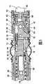
图3是图1和2所示工具的一些部件的局部横截视图;Figure 3 is a partial cross-sectional view of some components of the tool shown in Figures 1 and 2;
图4是图1和2所示工具的一些部件的局部横截视图;Figure 4 is a partial cross-sectional view of some components of the tool shown in Figures 1 and 2;
图5是图4所示安全阀的放大横截视图;Fig. 5 is an enlarged cross-sectional view of the safety valve shown in Fig. 4;
图6是图1-5所示工具的替代实施例的横截视图;Figure 6 is a cross-sectional view of an alternative embodiment of the tool shown in Figures 1-5;
图7是图6所示区域A的放大视图;Figure 7 is an enlarged view of area A shown in Figure 6;
图8是图6-7所示安全阀的放大横截视图;并且Figure 8 is an enlarged cross-sectional view of the relief valve shown in Figures 6-7; and
图9是图8所示安全阀的替代实施例的横截视图。9 is a cross-sectional view of an alternative embodiment of the relief valve shown in FIG. 8 .
具体实施方式Detailed ways
参照图1,其中示出结合本发明特点的工具10的分解透视图。虽然本发明将参照图中所示的示例性实施例描述,然而应当理解到本发明能以许多替代形式的实施例具体化。另外,能使用任何适合的尺寸、形状或类型的元件或材料。Referring to Figure 1, there is shown an exploded perspective view of a tool 10 incorporating features of the present invention. Although the invention will be described with reference to the exemplary embodiments shown in the drawings, it should be understood that the invention can be embodied in many alternative forms of embodiments. In addition, any suitable size, shape or type of elements or materials could be used.
工具10是手持液压操作的电池供电工具。然而,本发明的特点能用于非电池操作的工具中。工具10是压接工具,用于将电连接器压接到导体上,比如举例来说电缆。然而,本发明的特点能用于任何适合类型的液压操作的工具,比如举例来说切割工具。Tool 10 is a hand held hydraulically operated battery powered tool. However, features of the present invention can be used in non-battery operated tools. Tool 10 is a crimping tool for crimping electrical connectors onto conductors, such as, for example, cables. However, features of the present invention can be used with any suitable type of hydraulically operated tool, such as for example a cutting tool.
参照图2,工具10一般包括泵12、电机14、将电机连接至泵的传输机构16、电池18、流体储存器20、工作头部22以及壳体24。工具10具有用户致动的控制器25,比如举例来说按钮或摇臂开关。然而,在替代实施例中,能提供任何适合类型的用户致动控制。在这个实施例中,工作头部22包括框架26、两个棘爪28和辊子30(参见图4)。然而,在替代实施例中,可提供任何适合类型的工作头部。棘爪28在枢转连接32处可枢转地连接至框架26。棘爪的前端适合可移除地接收压接模。然而,在替代实施例中,工作头部能是无模的压接头部。辊子30相对于棘爪28的后端定位,并且能在棘爪的后端之间推动。枢轴连接32能由棘爪孔中的牵簧(举例来说参见图6)来协助,以便在冲头34(参见图4)处于向后位置时朝着打开位置偏压棘爪28。Referring to FIG. 2 , the tool 10 generally includes a
参照图3和4,泵12能包括任何适合的泵。然而,在这个实施例中,泵是摆板泵,比如在美国专利申请No.11/429,039中所描述的,该专利申请的全部内容通过参考结合于此。泵12包括框架36。框架36具有形成冲头气缸38的前端。冲头34定位于冲头气缸38中并且由冲头弹簧34朝着向后位置偏压。冲头34的前端相对于辊子30定位。冲头34能由液压流体向前移动以将辊子30向前移动,并且因而,将棘爪28的后端扩展隔开。这引起棘爪的前端朝着彼此移动。Referring to Figures 3 and 4, the
框架36形成从活塞通道42至冲头位于冲头气缸38处的后端的液压管道。各种止回阀和释放和/或安全阀也优选地定位于液压管道中。框架36的外侧还形成储存器20的一部分。囊44附着于框架36的环状凹陷46处以形成储存器20。然而,在替代实施例中,能提供任何适合类型的液压流体储存器或液压流体供应源。The
泵12包括定位于活塞通道42中的活塞泵元件48。活塞泵元件48延伸出框架36的后端并且由弹簧50向外偏压。活塞元件48布置于活塞通道42中,用于往复向前和向后移动。在活塞元件48向后移动时,其将液压流体从储存器20穿过管道70并且经过止回阀72吸入活塞腔42。在活塞元件48向前移动时,其朝着冲头气缸38推动液压流体穿过管道74并且经过止回阀76。
框架36的后端包括枢转元件孔52以及至少一个弹簧孔54。枢转元件56可枢转地定位于孔52中。在这个实施例中,枢转元件56是球状物。然而,在替代实施例中,能提供摆板60至框架36后端的任何适合的可枢转连接。弹簧58(比如盘簧)定位于每个孔54中。在这个实施例中,仅提供一个盘簧58。然而,在替代实施例中,能提供两个至五个或更多盘簧。弹簧58定位在框架36的后端与活塞元件48相反的侧上并且其间具有枢转元件56。The rear end of the
传输机构16一般包括摆板60、传输机构外壳62、锥盘64以及齿轮箱66。齿轮箱66连接至电机14的输出轴。锥盘64连接至齿轮箱66的输出轴68。锥盘64的前端具有成角的前表面。该表面相对于中心轴线成角。前端还包括配重袋。The
用户接口或控制器25包括可枢转地连接至框架36或壳体24的致动杆94。杆94优选地由弹簧偏压于向外位置中。然而,在替代实施例中,能提供任何适合类型的用户致动控制器。在杆94由用户压下时,电机14致动。User interface or controller 25 includes an
如在图4中看到的,工具10包括液压流体释放系统78。释放系统78一般包括排出销80、排出阀82以及缩回杆84。缩回杆84是用户接口25的一部分。释放系统78将这些元件与管道86、88、90、92相结合地使用以将液压流体从冲头气缸38释放返回入储存器20。排出阀82具有用于将排出阀偏压于闭合位置中的弹簧。排出销80具有延伸出框架36的端部。缩回杆84可枢转地连接至框架36或壳体24。杆84可由弹簧相对于排出销80的外端偏压。然而,杆84优选地在壳体24上偏压远离排出销80。排出阀82的弹簧比杆84的弹簧要强。然而,杆能从图4中所示的原位向内和向外移动。杆84能由用户的手或手指压下以将排出销80向内移动。这能使排出阀82离位并且因此打开排出阀82以允许液压流体从冲头气缸38释放返回入储存器20。这允许冲头34向后缩回,引起压接棘爪打开。As seen in FIG. 4 , the tool 10 includes a hydraulic
工具10还包括液压流体安全系统96。安全系统96一般包括在冲头气缸38与储存器20之间连接至框架36的管道系统的安全阀98。在这个实施例中,安全阀98安装在管道90中接近管道92之处。参照图5,安全阀98一般包括阀主体100、阀锥体102和弹簧104。阀主体100包括入口106、出口108、调节螺钉110以及外径减小区段111。阀锥体102可移动地定位于阀主体内。弹簧104将阀锥体102偏压入与形成于入口106处的阀座112密封地接触。The tool 10 also includes a hydraulic
在冲头气缸38中的液压达到预定值时,阀锥体102的前部从阀座椅112离位(由于入口106处的液压)并且液压流体被允许从冲头气缸38流过入口106、流出出口108并且穿过管道92返回储存器20。如果没有达到预定值,安全阀98保持闭合。安全阀98可适合在其被打开时产生可听见的声音,比如“砰”。安全阀98还能适合保持打开直到达到预定的较低液压。When the hydraulic pressure in the
除了上面提到的可听见信号发送系统以外,工具10包括第二信号发送系统,其包括触觉反馈系统。在这个实施例中,触觉反馈系统包括杆84、排出销80以及杆84的弹簧。触觉反馈系统结合至管道系统并且适合将预定事件出现的信号发送给用户。例如,预定事件能是安全阀98被致动或达到预定液压。In addition to the audible signaling system mentioned above, tool 10 includes a second signaling system that includes a tactile feedback system. In this embodiment, the tactile feedback system includes a
触觉反馈系统将触觉反馈至用户的手,因为用户的手将在用户致动杆94时接触杆84。更具体地,在阀98打开时,来自冲头气缸38的一些液压流体将被推入管道90中并且将排出销80向外推动。杆84将向外移动,同时杆84的弹簧被偏转。在阀98再次闭合时,杆84的弹簧将杆移动返回至其原位;向内返回。由于活塞泵元件48的往复运动,阀98将反复地打开和闭合直到用户停止致动杆94。因而,在这个实施例中,触觉反馈系统将引起杆84上下移动,其类型为在用户的手上产生振动效果;因为阀98将反复打开和闭合。然而,在替代实施例中,触觉反馈可以不是振动的。例如,触觉反馈能仅包括一个触觉摇晃类型的信号。这可以伴有如下面描述的替代实施例中提到的可听见的“砰”声。The tactile feedback system provides tactile feedback to the user's hand as the user's hand will contact the
在上述实施例中,工具具有信号发送系统,用于将预定事件出现的信号发送给用户,更具体地,信号发送系统适合产生至少两种不同的信号给用户。在所述实施例中,这两种信号包括可听见信号和触觉信号。然而,在替代实施例中,能提供超过两种类型的信号,并且信号能包括除可听见和/或触觉以外的信号,比如举例来说,可视的。在另一种类型的替代实施例中,可仅提供触觉信号发送系统。In the above embodiments, the tool has a signaling system for signaling the occurrence of a predetermined event to the user, more specifically, the signaling system is adapted to generate at least two different signals to the user. In the described embodiment, the two signals include an audible signal and a tactile signal. However, in alternative embodiments, more than two types of signals can be provided, and the signals can include signals other than audible and/or tactile, such as, for example, visual. In another type of alternative embodiment, only a tactile signaling system may be provided.
本发明能涉及电池供电的液压压接工具。本发明能给操作者提供触觉反馈,显示压接已经完成。一旦管道系统中的液压达到预定值,即一旦达到安全阀设置压力,就能产生触觉反馈。仅作为举例来说,对于六吨的压接或切割工具来说安全阀设置压力可以是大约4000-10000psi,或对于三吨的压接或切割工具可以是大约2000-6000psi。根据期望的特定压接/切割力,大于或小于大约2000-10000psi的其它安全阀设置压力是预期的。The invention can relate to battery powered hydraulic crimping tools. The present invention can provide tactile feedback to the operator, indicating that the crimping has been completed. Haptic feedback can be generated once the hydraulic pressure in the piping system reaches a predetermined value, ie once the safety valve set pressure is reached. By way of example only, the relief valve set pressure may be approximately 4000-10000 psi for a six ton crimping or cutting tool, or approximately 2000-6000 psi for a three ton crimping or cutting tool. Other relief valve set pressures greater or less than about 2000-10000 psi are contemplated depending on the specific crimping/cutting force desired.
具有上述实施例,电池供电的液压压接工具10能由结合至直流电机14的直流电池18供电,直流电机14具有结合至也具有输出轴的齿轮箱66的输出轴。在轴旋转时,锥盘64旋转,其在推力轴承上旋转并且将旋转运动转换为摆板60的线性运动。这个活动引起泵12和泵弹簧的往复运动。这个往复运动将液压流体从储存器20泵送至活塞冲头34的向后区段。当泵在朝着工具10后部的方向上移动时,流体从储存器20穿过入口止回阀72被吸入。当泵在朝着工具10前部的方向上移动时,流体被推动穿过出口止回阀76并且在活塞冲头34之后进入气缸38。在流体填满气缸38时,活塞冲头34朝着工具10的前部前进,迫使托架和辊子30到棘爪的凸轮表面上。这时,棘爪闭合并且压接槽或模(未示出)压接工件。With the embodiments described above, the battery powered hydraulic crimping tool 10 can be powered by a
气缸38中的压力将上升至预定的安全阀设置压力。当压力在气缸端口中上升时,安全阀98承受与气缸38相同的压力。在压力处于预定的阀设置压力时,阀锥体102升起离开阀座112并且锥体102远离端口106地穿梭并且允许流体穿过端口108返回至储存器20。这时,一些流体被允许在位于由外径减小的区段111产生的小直径环状通路113处穿过阀体并且进入保持排出销80的管道。The pressure in
因为大多溢出流体通向储存器20,保持排出销80的管道中产生的液压比气缸38中的液压低很多。然而,这仍然是足以推动排出销80的压力。施加至排出销80的压力出现非常小的时期并且引起排出销80在与排出阀82相反的方向上穿梭。排出阀弹簧定尺寸为相对较硬并且进入保持排出销80的管道中的压力脉冲不能提供足够的力来移动这个弹簧;所以排出阀82保持闭合。当排出销80在与排出阀82相反的方向上穿梭时,其冲击将达到预定安全阀压力设置的触觉反馈提供给操作者的缩回触发器84,并且因此压接完成。Since most of the overflow fluid goes to the
另外应当注意到,操作者能在在任何时间点通过简单地致动缩回杆84并且压下排出销80来中断压接循环,从而致动排出阀。此时,允许流体从气缸38穿过管道、穿过排出阀82,并且穿过位于阀98处的环状通路排出返回储存器20。这个活动将引起压接棘爪打开。It should also be noted that the operator can interrupt the crimping cycle at any point by simply actuating the retract
在一种类型的替代实施例中,泵能设在工具外侧。在另一种类型的替代实施例中,工具能是气动工具而不是液压工具。优选地工具是轻便手持的,但是在替代实施例中,仅工具的一部分可由用户的手保持。In one type of alternative embodiment, the pump can be located outside the tool. In another type of alternative embodiment, the tool could be a pneumatic tool rather than a hydraulic tool. Preferably the tool is hand-held lightly, but in alternative embodiments only a portion of the tool may be held by the user's hand.
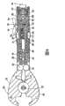
现在参照图6-8,示出一种类型的液压工具的替代实施例。在这个实施例中,工具120一般包括泵12、电机14、将电机连接至泵的传输机构16、电池18、流体储存器20、工作头部22以及壳体24`。工具10具有包括摇臂开关组件的用户致动的控制器25`。然而,在替代实施例中,能提供任何适合类型的用户致动的控制器。在这个实施例中,工作头部22包括安装在棘爪28的孔中以将棘爪28的后端朝着彼此偏压的拉伸弹簧122。然而,在替代实施例中,能提供任何适合类型的工作头部。棘爪28可在枢转连接32处枢转地连接至框架26。辊子30相对于棘爪28的后端定位;并且能在棘爪28的后端之间推动。Referring now to FIGS. 6-8 , an alternate embodiment of one type of hydraulic tool is shown. In this embodiment, the
框架26及其液压管道、以及框架26中的止回阀与图1-5中所示和描述的相同。然而,安全阀是不同的。如能在图7和8中更详细地看到的,安全阀124一般包括阀主体100`、阀锥体102和弹簧104。阀主体100`包括具有入口106的前部元件126、具有出口108的主元件128以及调节螺钉110`。阀锥体102可移动地定位于阀主体100`中。弹簧104将阀锥体102偏压入与形成于入口106后部的阀座112密封地接触。阀主体100`具有外径减小区段111`。在图5中所示的实施例中,外径减少区段111`从阀主体的后面延伸至出口108后面的位置。在这个实施例中,外径减小区段111`从主元件128的后部延伸至出口108前面的位置。因而,形成于框架16与阀124之间的环状通道113`延伸至管道92。The
调节螺钉110`螺旋入主元件128的后端并且弹簧104的后端与之相靠。通过调整螺钉110`相对于主元件128的位置来调整由弹簧104相对于阀锥体102施加的力。与螺钉110不同,螺钉110`具有延伸穿过螺钉110`的孔径130。这个孔径130提供为增强被移动打开的锥体102对排出销80的触觉反馈信号的液压效果。尤其是在阀锥体102向后移动时(当其在预定液压下打开时),区域132中的液压流体被推出孔径130进入管道90、88以便非常迅速并且突然地将排出销80推动至其向外位置。销80又非常迅速并且突然地向外推动用户控制器25`的释放杆区段134。这就由释放杆区段134在用户手上引起摇晃。The adjustment screw 110' is threaded into the rear end of the
在这个实施例中,摇晃是单个信号;不是反复类型的振动信号。然而,摇晃的强度足以让用户清楚地注意到;优选地即使用户带上手套。在这个实施例中,信号是单独信号而不是振动。液压流体从区域132的移动引起排出销80向外移动。液压流体穿过通路113`的移动不会显著地辅助由销80提供的触觉反馈,因为从区域132的液压流体移动是非常大的。通路113`仅仅主要提供用于在安全阀82被手动地打开时液压流体进入管道92的路径。In this embodiment, the shaking is a single signal; not a repetitive type vibration signal. However, the shaking is strong enough for the user to clearly notice; preferably even if the user is wearing gloves. In this embodiment, the signal is a single signal rather than a vibration. Movement of hydraulic fluid from
在这个实施例中,触觉反馈系统还提供关于预定事件的放大声频信号。尤其在排出销80处于其闭合的原位,并且用户控制器25`被致动以便致动电机14时,排出销80的外端与释放杆区段134隔开。在预定液压事件出现并且安全阀124`打开时,排出销80的向外快速移动引起控制器25`的表面136上的撞击,这在框架26的外侧产生可听见的“砰”声,这个声音大于以前由常规工具中提供的内部“砰”声。这个外部听觉信号能通过与由排出销80向外移动提供的同时地提供的另外的内部“砰”来补充或增大。替代地,听觉信号能仅内部地引起,比如由快速内部液压流体移动的声音引起;没有在框架26外部。因而,本发明能提供一种在将触觉信号提供给用户的同时增大音量的听觉信号。In this embodiment, the tactile feedback system also provides amplified audio signals regarding predetermined events. The outer end of the
参照图9,示出安全阀的替代实施例。在这个实施例中,安全阀140包括阀主体100`、阀锥体102和弹簧104。阀主体100`包括具有入口106的前部元件126、具有出口108的主元件128,以及调节螺钉110;而不是调节螺钉110`。如上所述,阀主体100`具有外径减小区段111`。外径减小区段111`从主元件128的后端延伸至出口108前面的位置。因而,形成于框架26和阀124之间的环状通路113`延伸至管道92。Referring to Figure 9, an alternate embodiment of a relief valve is shown. In this embodiment, the
调节螺钉110螺旋入主元件128的后端并且弹簧104的后端与之相靠。通过调整螺钉110相对于主元件128的位置来调节由弹簧104相对于阀锥体102施加的力。与螺钉110`不同,螺钉110不具有延伸穿过螺钉110的孔径130。在阀锥体102向后移动时(当在预定的液压下打开时),区域132中的液压流体能移动经过锥体102的侧面从出口108流出。在阀锥体102向后移动时,来自阀140的液压流体能由进入入口106的流体的压力推动进入通路113`以引起排出销80被向外推动。这种类型的设计能减少在螺钉110中做出孔径130的需要,但是仍然提供触觉反馈,因为液压流体能在安全阀140打开时具有从安全阀140朝着排出阀82移动的能力。在替代实施例中,工具的附加或替代部件能用来在由工具的一部分获得预定的液压时给用户提供触感。The
应当理解到,前述仅是本发明的示例。各种替代和变型能由本领域的技术人员在不脱离本发明之下设计出。因此,本发明将涵盖所有这些落入所附权利要求范围内的替代、变型和变化。It should be understood that the foregoing is merely exemplary of the present invention. Various alternatives and modifications can be devised by those skilled in the art without departing from the invention. Accordingly, the present invention is to embrace all such alternatives, modifications and changes that fall within the scope of the appended claims.
Claims (13)
Translated fromChineseApplications Claiming Priority (5)
| Application Number | Priority Date | Filing Date | Title |
|---|---|---|---|
| US85172406P | 2006-10-13 | 2006-10-13 | |
| US60/851,724 | 2006-10-13 | ||
| US11/893,248US7487654B2 (en) | 2006-10-13 | 2007-08-15 | Hydraulic tool with tactile feedback |
| US11/893,248 | 2007-08-15 | ||
| PCT/US2007/020404WO2008048409A2 (en) | 2006-10-13 | 2007-09-20 | Hydraulic tool with tactile feedback |
Publications (2)
| Publication Number | Publication Date |
|---|---|
| CN101523325A CN101523325A (en) | 2009-09-02 |
| CN101523325Btrue CN101523325B (en) | 2011-11-23 |
Family
ID=39301954
Family Applications (1)
| Application Number | Title | Priority Date | Filing Date |
|---|---|---|---|
| CN2007800381302AActiveCN101523325B (en) | 2006-10-13 | 2007-09-20 | Hydraulic Tools with Haptic Feedback |
Country Status (4)
| Country | Link |
|---|---|
| US (1) | US7487654B2 (en) |
| EP (1) | EP2089785A2 (en) |
| CN (1) | CN101523325B (en) |
| WO (1) | WO2008048409A2 (en) |
Families Citing this family (26)
| Publication number | Priority date | Publication date | Assignee | Title |
|---|---|---|---|---|
| PL2043818T3 (en)* | 2006-08-25 | 2010-07-30 | Hans Oetiker Ag Maschinen Und Apparatefabrik | Manually actuated tongs having force monitoring |
| US7841223B2 (en) | 2006-10-12 | 2010-11-30 | Burndy Technology Llc | Rocker switch |
| USD673829S1 (en)* | 2009-10-02 | 2013-01-08 | Izumi Products Company | Battery operated oil hydraulic crimping tool |
| CN102781311B (en) | 2010-02-24 | 2016-09-21 | 优瑞技术公司 | Split type magnetic resonance imaging system |
| US8838308B2 (en) | 2010-05-27 | 2014-09-16 | Boxx Corp. | Two wheeled vehicle with modular features |
| US9000898B2 (en)* | 2012-08-16 | 2015-04-07 | Deere & Company | Electrohydraulic controller feedback system and method |
| USD734112S1 (en)* | 2012-09-25 | 2015-07-14 | Establissement Georges Renault | Riveting tool |
| USD716124S1 (en)* | 2013-09-30 | 2014-10-28 | Izumi Products Company | Battery operated oil hydraulic crimping tool and middle portion of the same |
| US10312653B2 (en) | 2015-05-06 | 2019-06-04 | Milwaukee Electric Tool Corporation | Hydraulic tool |
| ITUA20161807A1 (en)* | 2016-03-18 | 2017-09-18 | Cembre Spa | HYDRAULIC COMPRESSION OR CUTTING TOOL |
| CA3022406A1 (en)* | 2016-05-02 | 2017-11-09 | Hubbell Incorporated | In-line hydraulic crimp tool |
| USD834908S1 (en)* | 2016-12-22 | 2018-12-04 | Gustav Klauke Gmbh | Hand-held power tool and a display on a hand-held power tool |
| USD835487S1 (en) | 2017-05-15 | 2018-12-11 | Hubbell Incorporated | Handle for in-line power tools |
| EP3625006B1 (en) | 2017-05-15 | 2024-03-27 | Hubbell Incorporated | Portable in-line hydraulic tool |
| USD845729S1 (en)* | 2017-09-29 | 2019-04-16 | Izumi Products Company | Portable battery operated oil hydraulic tool |
| MX2020010668A (en) | 2018-04-10 | 2020-10-28 | Hubbell Inc | Portable in-line cutting tool with stabilizer. |
| US12264848B2 (en)* | 2018-09-05 | 2025-04-01 | Ojjo, Inc. | Systems, methods, and machines for joining truss foundation components without mechanical fasteners |
| US11621531B2 (en) | 2018-09-28 | 2023-04-04 | Hubbell Incorporated | Power tool with crimp localization |
| US11890763B2 (en)* | 2020-03-26 | 2024-02-06 | Ridge Tool Company | Threaded rod shearing mechanism |
| CN115917454A (en) | 2020-06-21 | 2023-04-04 | 哈勃股份有限公司 | Power tools with images of crimping |
| USD1042068S1 (en)* | 2021-05-19 | 2024-09-17 | Gustav Klauke Gmbh | Hydraulic press tool |
| CN113276072B (en)* | 2021-05-19 | 2025-06-13 | 艾默生精密工具技术(上海)有限公司 | Hydraulic tools |
| WO2023038989A1 (en) | 2021-09-07 | 2023-03-16 | Hubbell Incorporated | Tool with multi-stage trigger |
| EP4243222B1 (en)* | 2022-03-09 | 2024-05-15 | WEZAG GmbH & Co. KG | Crimping tool force sensor and crimping tool |
| USD1042074S1 (en) | 2022-09-07 | 2024-09-17 | Hubbell Incorporated | Handle for power tools |
| JP7550334B1 (en) | 2024-03-28 | 2024-09-12 | マクセルイズミ株式会社 | Power tools |
Citations (2)
| Publication number | Priority date | Publication date | Assignee | Title |
|---|---|---|---|---|
| US6398763B1 (en)* | 2000-02-16 | 2002-06-04 | Ultradent Products, Inc. | Syringe apparatus having a plunger tip with a flexible spring lever |
| US6834524B2 (en)* | 1999-09-22 | 2004-12-28 | Swagelok Company | Apparatus for swaging ferrules |
Family Cites Families (24)
| Publication number | Priority date | Publication date | Assignee | Title |
|---|---|---|---|---|
| US2444550A (en) | 1944-05-20 | 1948-07-06 | Electrol Inc | Hydraulic power pack unit |
| US2388462A (en) | 1944-07-19 | 1945-11-06 | Beeh Louis | Multiple metering pump |
| US2737168A (en) | 1949-10-22 | 1956-03-06 | Pratt & Whitney Co Inc | Fuel injection apparatus |
| DE2537794C2 (en)* | 1975-08-25 | 1985-09-26 | Alfred Honsel Nieten - und Metallwarenfabrik GmbH & Co, 5758 Fröndenberg | Pressure medium operated blind riveting tool |
| US4236878A (en) | 1978-09-29 | 1980-12-02 | Sankyo Electric Company Limited | Lubrication system for compressor unit |
| US4240280A (en) | 1979-02-08 | 1980-12-23 | Minnesota Mining And Manufacturing Company | Hand crimping tool |
| US4494398A (en)* | 1983-02-14 | 1985-01-22 | Midas International Corporation | Tubing expander apparatus |
| FR2563291A1 (en)* | 1984-04-20 | 1985-10-25 | Etude Methode Applic Sarl | HYDRAULIC CYLINDER WITH MANUAL CONTROL |
| USRE33714E (en) | 1984-06-29 | 1991-10-15 | Crimping tool | |
| US5152162A (en)* | 1990-06-27 | 1992-10-06 | Burndy Corporation | System and method for crimping articles |
| US5195042A (en) | 1990-06-27 | 1993-03-16 | Burndy Corporation | Apparatus and method for controlling crimping of articles |
| US5297417A (en) | 1992-09-18 | 1994-03-29 | Dana Corporation | Portable collet crimping apparatus |
| JPH06241161A (en) | 1993-02-15 | 1994-08-30 | Sanden Corp | Compressor |
| FR2708674B1 (en) | 1993-07-30 | 1996-05-15 | Dubuis | Volumetric piston pump driven by an alternating linear movement. |
| US5553478A (en)* | 1994-04-08 | 1996-09-10 | Burndy Corporation | Hand-held compression tool |
| US5727417A (en) | 1995-09-22 | 1998-03-17 | Greenlee Textron Inc. | Portable battery powered crimper |
| JP3990732B2 (en)* | 1996-06-07 | 2007-10-17 | イドロ レデュク | High pressure pump that can be used for any fluid |
| US6162024A (en)* | 1998-12-01 | 2000-12-19 | Spx Corporation | Constant horsepower continuously variable volume pump |
| US6510719B2 (en)* | 2000-04-28 | 2003-01-28 | Novartec @ Ag | Pressing tool and pressing process for extruding press fittings |
| US6453719B1 (en)* | 2000-07-28 | 2002-09-24 | Fci Usa, Inc. | Hydraulic tool with forward surrounding reservoir |
| US7094216B2 (en)* | 2000-10-18 | 2006-08-22 | Medrad, Inc. | Injection system having a pressure isolation mechanism and/or a handheld controller |
| US6564610B2 (en)* | 2001-06-18 | 2003-05-20 | Fci Usa, Inc. | Hydraulic tool having mechanical actuator with internal bypass valve |
| US6446482B1 (en)* | 2001-09-17 | 2002-09-10 | Fci Americas Technology, Inc. | Battery operated hydraulic compression tool with rapid ram advance |
| US6745611B2 (en)* | 2002-02-19 | 2004-06-08 | Fci Americas Technology, Inc. | Battery powered hydraulic tool |
- 2007
- 2007-08-15USUS11/893,248patent/US7487654B2/enactiveActive
- 2007-09-20EPEP07838586Apatent/EP2089785A2/ennot_activeWithdrawn
- 2007-09-20CNCN2007800381302Apatent/CN101523325B/enactiveActive
- 2007-09-20WOPCT/US2007/020404patent/WO2008048409A2/enactiveApplication Filing
Patent Citations (2)
| Publication number | Priority date | Publication date | Assignee | Title |
|---|---|---|---|---|
| US6834524B2 (en)* | 1999-09-22 | 2004-12-28 | Swagelok Company | Apparatus for swaging ferrules |
| US6398763B1 (en)* | 2000-02-16 | 2002-06-04 | Ultradent Products, Inc. | Syringe apparatus having a plunger tip with a flexible spring lever |
Also Published As
| Publication number | Publication date |
|---|---|
| EP2089785A2 (en) | 2009-08-19 |
| WO2008048409A2 (en) | 2008-04-24 |
| US20080087064A1 (en) | 2008-04-17 |
| WO2008048409A3 (en) | 2008-08-21 |
| US7487654B2 (en) | 2009-02-10 |
| CN101523325A (en) | 2009-09-02 |
Similar Documents
| Publication | Publication Date | Title |
|---|---|---|
| CN101523325B (en) | Hydraulic Tools with Haptic Feedback | |
| US7841223B2 (en) | Rocker switch | |
| CN100369695C (en) | Hydraulic tools with quick-travel rams | |
| US6564610B2 (en) | Hydraulic tool having mechanical actuator with internal bypass valve | |
| US5425164A (en) | Hand-tool system for installing blind fasteners | |
| US20080282763A1 (en) | Hydraulic tool | |
| CN219827299U (en) | hydraulic tools | |
| US8307690B2 (en) | Hand-tool system for installing blind fasteners | |
| US7383894B2 (en) | Pneumatic hammer drill (I) | |
| JPH0464835B2 (en) | ||
| JP2020537596A (en) | Compressed air nailer with safety actuator | |
| US7540220B2 (en) | Electronic torque wrench having a trip unit | |
| JP2019521865A (en) | Air nailer with single and contact trigger | |
| US7140597B2 (en) | Carpet stretching device | |
| CN222697131U (en) | Hydraulic Hand Tools | |
| JPH085028Y2 (en) | Hydraulic tool with built-in bite release mechanism | |
| JPWO2020016917A1 (en) | Valve device | |
| JPH11247806A (en) | Hydraulic cylinder | |
| JP2001242941A (en) | Device for fluid pressure control | |
| EP1690477A1 (en) | Carpet stretching device |
Legal Events
| Date | Code | Title | Description |
|---|---|---|---|
| C06 | Publication | ||
| PB01 | Publication | ||
| C10 | Entry into substantive examination | ||
| SE01 | Entry into force of request for substantive examination | ||
| C14 | Grant of patent or utility model | ||
| GR01 | Patent grant | ||
| ASS | Succession or assignment of patent right | Owner name:HUBBELL INC. Free format text:FORMER OWNER: FCI S.A. Effective date:20120203 | |
| C41 | Transfer of patent application or patent right or utility model | ||
| TR01 | Transfer of patent right | Effective date of registration:20120203 Address after:American Connecticut Patentee after:Hubbell Inc. Address before:Versailles France Patentee before:FCI Corp. |