CN101523267B - Illuminator method and device - Google Patents
Illuminator method and deviceDownload PDFInfo
- Publication number
- CN101523267B CN101523267BCN2007800377684ACN200780037768ACN101523267BCN 101523267 BCN101523267 BCN 101523267BCN 2007800377684 ACN2007800377684 ACN 2007800377684ACN 200780037768 ACN200780037768 ACN 200780037768ACN 101523267 BCN101523267 BCN 101523267B
- Authority
- CN
- China
- Prior art keywords
- light
- entrance pupil
- luminaire device
- ray guide
- point
- Prior art date
- Legal status (The legal status is an assumption and is not a legal conclusion. Google has not performed a legal analysis and makes no representation as to the accuracy of the status listed.)
- Expired - Fee Related
Links
- 238000000034methodMethods0.000titleabstractdescription9
- 238000003384imaging methodMethods0.000claimsabstractdescription191
- 210000001747pupilAnatomy0.000claimsabstractdescription184
- 230000003287optical effectEffects0.000claimsabstractdescription145
- 238000005286illuminationMethods0.000claimsdescription70
- 230000005855radiationEffects0.000claimsdescription33
- 239000000463materialSubstances0.000claimsdescription23
- 239000000470constituentSubstances0.000claimsdescription20
- 239000007787solidSubstances0.000claimsdescription8
- 230000005670electromagnetic radiationEffects0.000claimsdescription7
- 230000008859changeEffects0.000claimsdescription5
- 229920003229poly(methyl methacrylate)Polymers0.000claimsdescription4
- 239000004926polymethyl methacrylateSubstances0.000claimsdescription4
- 239000004793PolystyreneSubstances0.000claimsdescription2
- 229920001577copolymerPolymers0.000claimsdescription2
- 239000004417polycarbonateSubstances0.000claimsdescription2
- 229920000515polycarbonatePolymers0.000claimsdescription2
- 230000015572biosynthetic processEffects0.000claims3
- 238000005755formation reactionMethods0.000claims3
- 230000009897systematic effectEffects0.000claims3
- 125000004122cyclic groupChemical group0.000claims1
- 229920002223polystyrenePolymers0.000claims1
- 238000007792additionMethods0.000abstract1
- 238000013461designMethods0.000description19
- 230000009466transformationEffects0.000description16
- 230000008901benefitEffects0.000description12
- 239000000243solutionSubstances0.000description11
- 238000009826distributionMethods0.000description10
- 238000004519manufacturing processMethods0.000description10
- 239000013598vectorSubstances0.000description10
- 230000005611electricityEffects0.000description5
- 238000010438heat treatmentMethods0.000description5
- 239000004033plasticSubstances0.000description5
- 229920003023plasticPolymers0.000description5
- 238000010586diagramMethods0.000description4
- 238000009499grossingMethods0.000description4
- 238000007493shaping processMethods0.000description4
- 238000000844transformationMethods0.000description4
- 238000013459approachMethods0.000description3
- 230000009286beneficial effectEffects0.000description3
- 238000010276constructionMethods0.000description3
- 238000007516diamond turningMethods0.000description3
- 230000004907fluxEffects0.000description3
- 239000007788liquidSubstances0.000description3
- XLYOFNOQVPJJNP-UHFFFAOYSA-NwaterSubstancesOXLYOFNOQVPJJNP-UHFFFAOYSA-N0.000description3
- PXHVJJICTQNCMI-UHFFFAOYSA-NNickelChemical compound[Ni]PXHVJJICTQNCMI-UHFFFAOYSA-N0.000description2
- 238000006243chemical reactionMethods0.000description2
- 239000012141concentrateSubstances0.000description2
- 239000012530fluidSubstances0.000description2
- 239000011521glassSubstances0.000description2
- 238000001746injection mouldingMethods0.000description2
- 238000005259measurementMethods0.000description2
- 238000005457optimizationMethods0.000description2
- 239000004038photonic crystalSubstances0.000description2
- 230000002207retinal effectEffects0.000description2
- 239000000758substrateSubstances0.000description2
- WKBPZYKAUNRMKP-UHFFFAOYSA-N1-[2-(2,4-dichlorophenyl)pentyl]1,2,4-triazoleChemical compoundC=1C=C(Cl)C=C(Cl)C=1C(CCC)CN1C=NC=N1WKBPZYKAUNRMKP-UHFFFAOYSA-N0.000description1
- 230000004075alterationEffects0.000description1
- 230000003667anti-reflective effectEffects0.000description1
- 230000005540biological transmissionEffects0.000description1
- 238000004364calculation methodMethods0.000description1
- 239000011248coating agentSubstances0.000description1
- 238000000576coating methodMethods0.000description1
- 239000000084colloidal systemSubstances0.000description1
- 238000010411cookingMethods0.000description1
- 238000005520cutting processMethods0.000description1
- 230000003247decreasing effectEffects0.000description1
- 229910003460diamondInorganic materials0.000description1
- 239000010432diamondSubstances0.000description1
- 230000000694effectsEffects0.000description1
- 238000010894electron beam technologyMethods0.000description1
- 238000005516engineering processMethods0.000description1
- 239000000835fiberSubstances0.000description1
- 239000003292glueSubstances0.000description1
- 238000000265homogenisationMethods0.000description1
- 238000007654immersionMethods0.000description1
- 238000003754machiningMethods0.000description1
- 238000012423maintenanceMethods0.000description1
- 238000013507mappingMethods0.000description1
- 238000013178mathematical modelMethods0.000description1
- 238000000386microscopyMethods0.000description1
- 238000012986modificationMethods0.000description1
- 230000004048modificationEffects0.000description1
- 229910052759nickelInorganic materials0.000description1
- 239000002245particleSubstances0.000description1
- 230000010287polarizationEffects0.000description1
- 238000010248power generationMethods0.000description1
- 238000012545processingMethods0.000description1
- 238000004064recyclingMethods0.000description1
- 210000001525retinaAnatomy0.000description1
- 238000013341scale-upMethods0.000description1
- 239000004065semiconductorSubstances0.000description1
- 230000003595spectral effectEffects0.000description1
- 238000001228spectrumMethods0.000description1
Images


Classifications
- F—MECHANICAL ENGINEERING; LIGHTING; HEATING; WEAPONS; BLASTING
- F21—LIGHTING
- F21V—FUNCTIONAL FEATURES OR DETAILS OF LIGHTING DEVICES OR SYSTEMS THEREOF; STRUCTURAL COMBINATIONS OF LIGHTING DEVICES WITH OTHER ARTICLES, NOT OTHERWISE PROVIDED FOR
- F21V5/00—Refractors for light sources
- F21V5/04—Refractors for light sources of lens shape
- F21V5/046—Refractors for light sources of lens shape the lens having a rotationally symmetrical shape about an axis for transmitting light in a direction mainly perpendicular to this axis, e.g. ring or annular lens with light source disposed inside the ring
- H—ELECTRICITY
- H10—SEMICONDUCTOR DEVICES; ELECTRIC SOLID-STATE DEVICES NOT OTHERWISE PROVIDED FOR
- H10H—INORGANIC LIGHT-EMITTING SEMICONDUCTOR DEVICES HAVING POTENTIAL BARRIERS
- H10H20/00—Individual inorganic light-emitting semiconductor devices having potential barriers, e.g. light-emitting diodes [LED]
- H10H20/80—Constructional details
- G—PHYSICS
- G02—OPTICS
- G02B—OPTICAL ELEMENTS, SYSTEMS OR APPARATUS
- G02B19/00—Condensers, e.g. light collectors or similar non-imaging optics
- G02B19/0004—Condensers, e.g. light collectors or similar non-imaging optics characterised by the optical means employed
- G02B19/0028—Condensers, e.g. light collectors or similar non-imaging optics characterised by the optical means employed refractive and reflective surfaces, e.g. non-imaging catadioptric systems
- G—PHYSICS
- G02—OPTICS
- G02B—OPTICAL ELEMENTS, SYSTEMS OR APPARATUS
- G02B19/00—Condensers, e.g. light collectors or similar non-imaging optics
- G02B19/0033—Condensers, e.g. light collectors or similar non-imaging optics characterised by the use
- G02B19/0047—Condensers, e.g. light collectors or similar non-imaging optics characterised by the use for use with a light source
- G02B19/0061—Condensers, e.g. light collectors or similar non-imaging optics characterised by the use for use with a light source the light source comprising a LED
- F—MECHANICAL ENGINEERING; LIGHTING; HEATING; WEAPONS; BLASTING
- F21—LIGHTING
- F21V—FUNCTIONAL FEATURES OR DETAILS OF LIGHTING DEVICES OR SYSTEMS THEREOF; STRUCTURAL COMBINATIONS OF LIGHTING DEVICES WITH OTHER ARTICLES, NOT OTHERWISE PROVIDED FOR
- F21V13/00—Producing particular characteristics or distribution of the light emitted by means of a combination of elements specified in two or more of main groups F21V1/00 - F21V11/00
- F21V13/02—Combinations of only two kinds of elements
- F21V13/04—Combinations of only two kinds of elements the elements being reflectors and refractors
- F—MECHANICAL ENGINEERING; LIGHTING; HEATING; WEAPONS; BLASTING
- F21—LIGHTING
- F21V—FUNCTIONAL FEATURES OR DETAILS OF LIGHTING DEVICES OR SYSTEMS THEREOF; STRUCTURAL COMBINATIONS OF LIGHTING DEVICES WITH OTHER ARTICLES, NOT OTHERWISE PROVIDED FOR
- F21V7/00—Reflectors for light sources
- F21V7/0091—Reflectors for light sources using total internal reflection
- F—MECHANICAL ENGINEERING; LIGHTING; HEATING; WEAPONS; BLASTING
- F21—LIGHTING
- F21Y—INDEXING SCHEME ASSOCIATED WITH SUBCLASSES F21K, F21L, F21S and F21V, RELATING TO THE FORM OR THE KIND OF THE LIGHT SOURCES OR OF THE COLOUR OF THE LIGHT EMITTED
- F21Y2115/00—Light-generating elements of semiconductor light sources
- F21Y2115/10—Light-emitting diodes [LED]
- G—PHYSICS
- G02—OPTICS
- G02B—OPTICAL ELEMENTS, SYSTEMS OR APPARATUS
- G02B21/00—Microscopes
- G02B21/06—Means for illuminating specimens
Landscapes
- Physics & Mathematics (AREA)
- General Physics & Mathematics (AREA)
- Optics & Photonics (AREA)
- Engineering & Computer Science (AREA)
- General Engineering & Computer Science (AREA)
- Lenses (AREA)
- Non-Portable Lighting Devices Or Systems Thereof (AREA)
- Projection Apparatus (AREA)
Abstract
Description
Translated fromChinese技术领域technical field
本发明的示例性且非限定性实施例总体涉及辐射成像,特别涉及辐射的收集、校准和会聚。更具体而言,这些实施例涉及光学系统的特定组元,所述组元将大角度的光线捕获到系统光轴,并将这些光线收集并重新分配,以形成对象或数据的照明质量图像。 Exemplary and non-limiting embodiments of the invention relate generally to radiation imaging, and more particularly to collection, collimation and convergence of radiation. More specifically, these embodiments relate to specific components of optical systems that capture large angle rays of light onto the system optical axis and collect and redistribute these rays to form illumination-quality images of objects or data. the
背景技术Background technique
怎样收集从特定光源发射的所有光,并进一步将光束成形为期望形式是一个公知的问题。对许多应用的一种理想解决方案是通过利用发射到绕光源的半球的光线来将光源成像。这里术语“成像”并不是指以最小化的象差来形成图像,而仅仅是用足够的照明质量成像。 How to collect all the light emitted from a particular light source and further shape the beam into a desired form is a known problem. An ideal solution for many applications is to image a light source by emitting light into a hemisphere around the source. The term "imaging" here does not mean forming an image with minimized aberrations, but merely imaging with sufficient illumination quality. the
一种公知的方法是使用高NA(数值孔径)物镜,例如非球面摄取透镜系统或显微镜物镜。这些解决方案或者相对于收集的展度(etendue)太大,或者不能从物体形成足够良好的图像。这些系统还可能很复杂且昂贵。这样的内容采取不同的方法。不同地,本发明的实施例通过使用与成像系统光轴成大角度发射的光线(例如,侧发射光线)而使得有可能形成物体的照明质量成像。 One known approach is to use high NA (numerical aperture) objectives, such as aspheric capture lens systems or microscope objectives. These solutions are either too large relative to the etendue of the collection, or do not form a sufficiently good image from the object. These systems can also be complex and expensive. Such content takes a different approach. Differently, embodiments of the present invention make possible illumination-quality imaging of objects by using rays emitted at large angles to the optical axis of the imaging system (eg, side-emitting rays). the
如果需要收集从光源发射的所有光,而所述光源处于其折射率n大于周围材料折射率(典型为空气,n=1)的材料之内,这时光的收集问题变得更加困难。典型地,仅当光源在空气中时,才有可能进行大角度收集。如果光源被封装在更高折射率的材料中,典型的收集光学元件趋向于太大而不能使用。此外,许多典型的光学收集方案(诸如收集透镜、TIR准直仪、锥形光导管、抛物面聚光镜)仅仅收集光,而需要其他组元来将光束 成形为期望的形式,例如均匀矩形。这导致更大的光学系统尺寸,并由于增加的分立组元数目或光束的增加的展度而导致额外的损耗。本发明的实施例对于该问题的解决在于即使在物体处于折射率大于周围材料的材料中时,描述的组元也使得有可能在大角度形成物体的图像。 The light collection problem becomes more difficult if there is a need to collect all the light emitted from a light source within a material whose refractive index n is greater than that of the surrounding material (typically air, n=1). Typically, wide angle collection is only possible when the light source is in air. Typical collection optics tend to be too large to be used if the light source is encapsulated in a higher index material. Furthermore, many typical optical collection schemes (such as collection lenses, TIR collimators, tapered light pipes, parabolic condensers) only collect light while requiring other components to shape the beam into a desired form, such as a uniform rectangle. This results in larger optical system size and additional losses due to increased number of discrete elements or increased etendue of the beam. Embodiments of the present invention solve this problem in that the described components make it possible to form images of the object at large angles even when the object is in a material with a higher refractive index than the surrounding material. the
在许多应用中,有利的是具有很低F数的物镜,技术上为超高数值孔径,其不需要完美的成像但是有很高的通量。本发明的实施例对该问题的解决在于这里描述的组元的数值孔径可以等于有待成像的物体周围的材料的折射率。 In many applications, it is advantageous to have objectives with very low F-numbers, technically ultra-high numerical apertures, which do not require perfect imaging but have high throughput. Embodiments of the present invention solve this problem in that the numerical aperture of the components described herein may be equal to the refractive index of the material surrounding the object to be imaged. the
对于物体或数据需要从远离光轴的角度成像的情况还有其他的设计考虑。例如,在一些应用中,由于其他使用,光轴被阻隔或者不可用于直接成像,并且仍然需要以很高的通量照明物体。下面将会看到,本发明的实施例也可以解决这样的问题。 There are additional design considerations for cases where objects or data need to be imaged from angles away from the optical axis. For example, in some applications the optical axis is blocked or not available for direct imaging due to other uses, and the object still needs to be illuminated at very high flux. As will be seen below, embodiments of the present invention can also address such problems. the
在小型LED投影仪中,一个难题是如何将来自LED芯片的光穿过矩形微显示器和投影透镜耦合到屏幕上。这必需有效地在一个很小空间内完成,且仍然提供均匀的图像质量。共有的美国专利No.7,059,728通过在光介质内部的一侧封入LED光源,在另一侧封入反射衬底,全面描述和设计了这样的考虑因素。来自LED非点光源的光分布遍及整个光介质。由于具有微尺度衍射和/或折射表面图形的反射和透射表面,分布的光被收集到具有相对均匀强度的线性输出中。但是,在那些技术考虑之外,照明组元需要以合理的成本能够批量生产。这些内容对该难题的进一步解决在于,这里详述的实施例提供一种照明系统和用于基于LED(或其他光源)的小型投影仪的方法,具有很高的效率和良好的均匀性,并且进一步地能够高效批量生产并具鲁棒性。 One challenge in small LED projectors is how to couple the light from the LED chips to the screen through the rectangular microdisplay and projection lens. This must be done efficiently in a small space and still provide uniform image quality. Commonly owned US Patent No. 7,059,728 fully describes and designs such considerations by enclosing an LED light source on one side inside an optical medium and a reflective substrate on the other. The light from the LED non-point light source is distributed throughout the entire optical medium. Due to reflective and transmissive surfaces with microscale diffractive and/or refractive surface patterns, the distributed light is collected into a linear output with relatively uniform intensity. However, beyond those technical considerations, the lighting components need to be mass-producible at a reasonable cost. A further solution to this dilemma is that the embodiments detailed herein provide an illumination system and method for LED (or other light source) based compact projectors with high efficiency and good uniformity, and It is further capable of efficient mass production and robustness. the
最接近的已知现有技术可认为是全内反射TIR-准直仪,诸如在 
另外,许多应用要求将来自漫射光源的光会聚。一个很好的例子是太阳光辐射的会聚。在太阳光会聚方面,本发明人已知的现有系统存在的一些问题是,它们不能以接近最大会聚比例来会聚光,并且相对于它们递送的能量来说它们物理上都很大。一些重现还要求一些光学表面紧邻光会聚的位置,当使用最大会聚比例时,这会导致严重的问题,因为在光具有很高强度处光学表面将会受到影响。并且,对于现有技术中基于抛物面反射镜的会聚器,发热元件位于抛物面镜面之上,这是一种很困难的物理布置。本发明的实施例对这些关注方面的解决在于,描述的组元可用于以接近理论最大值的会聚比例会聚光,而不存在上述问题。具体地,根据以下内容的太阳光会聚器可表现出几乎最大可能的会聚比例,而没有光学表面靠近发热元件,发热元件在会聚器之下,这使得发热元件处于固定位置,因此只有会聚器需要追踪太阳的移动。 Additionally, many applications require that light from a diffuse light source be concentrated. A good example is the concentration of solar radiation. Some of the problems with existing systems known to the inventors in terms of concentration of sunlight are that they cannot concentrate light at near maximum concentration ratios, and they are all physically large relative to the energy they deliver. Some renditions also require some optical surfaces to be in the immediate vicinity of where the light converges, which can cause serious problems when using the maximum convergence ratio, as the optical surfaces will be affected where the light has a high intensity. Moreover, for the converging device based on the parabolic mirror in the prior art, the heating element is located on the parabolic mirror surface, which is a very difficult physical arrangement. Embodiments of the present invention address these concerns in that the described constituents can be used to concentrate light at a concentration ratio close to the theoretical maximum without the aforementioned problems. In particular, solar concentrators according to the following can exhibit almost the maximum possible concentration ratio without optical surfaces close to the heating element, which is under the concentrator, which allows the heating element to be in a fixed position, so that only the concentrator needs Track the movement of the sun. the
在其他领域,诸如显微镜或光学测量领域,特定应用需要光的亮点。这也是以下描述的实施例的有利配置。 In other fields, such as microscopy or optical measurement, bright spots of light are required for specific applications. This is also an advantageous configuration of the embodiments described below. the
发明内容Contents of the invention
根据本发明一个实施例的是一种装置,包括第一和第二光线导向件,其中至少第一光线导向件是环形的。该第一环形光线导向件限定旋转轴,并具有环形入射光瞳,所述入射光瞳适于以40和140度之间的到旋转轴的角度将入射到入射光瞳上的辐射成像。第一环形光线导向件还具有与所述入射光瞳相对的第一成像表面。第二光线导向件也限定同样的旋转轴,并具有与所述第一成像表面邻近的第二成像表面。 According to one embodiment of the present invention is an apparatus comprising first and second light guides, wherein at least the first light guide is annular. The first annular light guide defines an axis of rotation and has an annular entrance pupil adapted to image radiation incident on the entrance pupil at an angle to the axis of rotation of between 40 and 140 degrees. The first annular light guide also has a first imaging surface opposite the entrance pupil. The second light guide also defines the same axis of rotation and has a second imaging surface adjacent to said first imaging surface. the
根据本发明另一实施例的是一种方法,包括从沿光轴排布的光源以离光轴40和140度之间的角度的发射光,在圆形对称的光线导向配置的入射光瞳处接收发射的光,其中所述圆形对称配置围绕光轴圆形对称,然后将接收到的光通过所述圆形对称光线导向配置以基本平行于光轴的平均方向重新定向到出射光瞳。According to another embodiment of the present invention is a method comprising emitting light from a light source arranged along an optical axis at an angle between 40 and 140 degrees from the optical axis, an entrance pupil in a circularly symmetrical light guide arrangement Emitted light is received at , wherein the circularly symmetric configuration is circularly symmetric about the optical axis, and the received light is then redirected to the exit pupil by the circularly symmetric light-guiding configuration in a mean direction substantially parallel to the optical axis .
根据本发明另一实施例的是一种装置,包括至少一个绕轴基本圆柱对称的光线导向件;所述至少一个光线导向件被设置为将光线的至少一部分基本成像为图像,所述光线从非点状物体朝向所述至少一个光线导向件的入射光瞳发射。在包含所述轴和入射光瞳一部分的各个横截平面的每一个中,所述至少一个光线导向件被布置为,将来自非点状物体、且沿着各个横截平面朝向在各个横截平面上且在轴的一侧的入射光瞳的一部分发射的光线的各个子集在各个横截平面上成像为中间图像,并进一步将来自所述中间图像的光线的至少一部分在横截平面上基本成像为横截图像,其中所述横截图像基本与所述各个横截平面处的图像的横截面一致,使得所述光线的各个子集中没有光线穿过光线与至少一个光线导向组元的横截面的第一和最后交叉之间的轴,所述至少一个光线导向组元与所述入射光瞳的横截面位于轴的同一侧。 According to another embodiment of the present invention is an apparatus comprising at least one substantially cylindrically symmetric light guide about an axis; said at least one light guide being arranged to substantially image at least a portion of light from A non-point-shaped object is emitted towards the entrance pupil of the at least one light guide. In each of the respective cross-sectional planes containing the axis and a portion of the entrance pupil, the at least one light guide is arranged to direct light from a non-point-like object along the respective cross-sectional plane towards the Respective subsets of rays emitted by a portion of the entrance pupil in the plane and on one side of the axis are imaged as intermediate images on respective cross-sectional planes, and further at least a portion of rays from said intermediate images are imaged on the cross-sectional planes substantially imaging as a cross-sectional image, wherein the cross-sectional image substantially coincides with a cross-section of the image at each of the cross-sectional planes such that no ray in each subset of the rays passes through the ray and the at least one ray-guiding component An axis between the first and last intersections of the cross-sections, the at least one light-guiding component being on the same side of the axis as the cross-section of the entrance pupil. the
根据本发明另一实施例的是一种装置,包括至少一个绕旋转轴基本圆柱对称的光线导向组元。所述至少一个光线导向组元被布置为将光线的至少一部分基本成像为图像,所述光线从非点状物体朝向所述至少一个光线导向组元的入射光瞳发射。所述至少一个光线导向组元进一步被布置为将所述至少一个光线导向组元的入射光瞳基本成像到出射光瞳,使得入射光瞳上的每一个点基本沿着所述旋转轴的方向在出射光瞳上基本成像为点的投影。进一步地,所述至少一个光线导向组元被布置为使入射光瞳的基本所有点距离物体基本相同距离。所述至少一个光线导向组元还被布置为使得从入射光瞳到出射光瞳成像的任何子午光线中没有路径穿过入射光瞳和出射光瞳之间的旋转轴。 According to another embodiment of the present invention is a device comprising at least one light guiding element substantially cylindrically symmetrical about an axis of rotation. The at least one light directing component is arranged to substantially image at least a portion of the light rays emitted from the non-point-like object towards the entrance pupil of the at least one light directing component as an image. The at least one ray guiding component is further arranged to substantially image an entrance pupil of the at least one ray guiding component to an exit pupil such that each point on the entrance pupil is substantially along the direction of the axis of rotation Basically imaged as a projection of a point on the exit pupil. Further, the at least one light guiding component is arranged such that substantially all points of the entrance pupil are at substantially the same distance from the object. The at least one ray directing component is also arranged such that no path of any meridian ray imaged from the entrance pupil to the exit pupil passes through the axis of rotation between the entrance pupil and the exit pupil. the
根据本发明的照明器装置,其中所述至少一个光线导向件被设置为使得从非点状物体基本成像到图像的任何点在图像上形成斑 点,使得其均方根斑点尺寸基本小于图像的平均直径,其中所述均方根斑点尺寸小于图像的平均直径的四分之一,所述至少一个光线导向件被设置为使得从非点状物体到入射光瞳的平均距离显著大于从所述非点状物体到所述轴的平均距离,从非点状物体到入射光瞳的所述平均距离是从所述非点状物体到所述轴的平均距离的至少三倍,以及,其中所述至少一个光线导向件被设置为使得入射光瞳覆盖绕所述轴上最接近非点状物体的平均点的点至少0.1球面度的立体角。 A luminaire arrangement according to the invention, wherein said at least one light guide is arranged such that any point substantially imaged into the image from a non-point-like object forms a spot on the image such that its root mean square spot size is substantially smaller than the image's mean diameter, wherein the root mean square spot size is less than a quarter of the mean diameter of the image, and the at least one light guide is arranged such that the mean distance from the non-point-like object to the entrance pupil is significantly greater than from the the average distance from the non-point-shaped object to the axis, the average distance from the non-point-shaped object to the entrance pupil is at least three times the average distance from the non-point-shaped object to the axis, and wherein The at least one light guide is arranged such that the entrance pupil covers a solid angle of at least 0.1 steradian around a point on said axis closest to the mean point of the non-point-shaped object. the
根据本发明的照明器装置,其中所述至少一个光线导向组元被设置为使得从非点状物体基本成像到图像的任何点在图像上形成斑点,使得其均方根斑点尺寸基本小于图像的平均直径,其中所述均方根斑点尺寸小于图像的平均直径的四分之一,所述至少一个光线导向组元被设置为使得从非点状物体到入射光瞳的平均距离显著大于从所述物体到所述轴的平均距离,其中从非点状物体到入射光瞳的所述平均距离是从所述非点状物体到所述轴的平均距离的至少三倍,所述至少一个光线导向组元被设置为沿所述轴具有小于出射光瞳直径的长度,以及,其中所述至少一个光线导向组元被设置为使得入射光瞳覆盖绕所述轴上最接近非点状物体的平均点的点至少3球面度的立体角。 A luminaire arrangement according to the invention, wherein said at least one light directing component is arranged such that any point substantially imaged into the image from a non-point-like object forms a spot on the image such that its root mean square spot size is substantially smaller than the image's average diameter, wherein the root mean square spot size is less than a quarter of the average diameter of the image, and the at least one light guiding component is arranged such that the average distance from the non-point-like object to the entrance pupil is significantly greater than the average distance from the the average distance from the object to the axis, wherein the average distance from the non-point object to the entrance pupil is at least three times the average distance from the non-point object to the axis, and the at least one ray The guide element is arranged to have a length along said axis that is less than the diameter of the exit pupil, and wherein said at least one light guide element is arranged such that the entrance pupil covers an area around said axis closest to the non-point shaped object The average point is a solid angle of at least 3 steradians. the
附图说明Description of drawings
结合附图阅读接下来的具体描述会使得这些内容的各个方面更加清楚明显,其中: Reading the ensuing detailed description in conjunction with the accompanying drawings will make each aspect of these contents more obvious, among which:
图1A-B是现有技术TIR准直仪的各种示图; 1A-B are various diagrams of prior art TIR collimators;
图2A-D示出本发明的实施例提出的数学模型,图2E示出双透镜布置; Figure 2A-D shows the mathematical model that the embodiment of the present invention proposes, and Figure 2E shows double lens arrangement;
图3示出折反射光线导向组元; Figure 3 shows a catadioptric light guiding component;
图4A和4C-4F示出根据本发明的实施例用于离光轴大角度的各光学通道的横截面,图4B示出用于离光轴小角度的这样的通道; Figures 4A and 4C-4F show cross-sections of individual optical channels for large angles from the optical axis, and Figure 4B shows such channels for small angles from the optical axis, according to embodiments of the present invention;
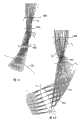
图5A-E示出照明器的各种实施例和根据本发明实施例形成光学通道的光线导向件的进一步细节; 5A-E illustrate various embodiments of luminaires and further details of light guides forming optical channels according to embodiments of the present invention;
图6A-6B示出照明器的另一实施例,图6C-6D示出通过图6A-6B的照明器的光学通道的光线追踪,图6E是图6A-6B的照明器的展开图; Figures 6A-6B illustrate another embodiment of the illuminator, Figures 6C-6D illustrate ray tracing through the optical channel of the illuminator of Figures 6A-6B, Figure 6E is an expanded view of the illuminator of Figures 6A-6B;
图7A-C示出根据本发明实施例的照明器的输出光瞳处的照明锥的数学构造和相对尺度; 7A-C illustrate the mathematical construction and relative dimensions of the illumination cone at the output pupil of an illuminator according to an embodiment of the invention;
图7D是示出从光源通过整个系统到显示屏的空间和角度分布的示意图; Figure 7D is a schematic diagram showing the spatial and angular distribution from the light source through the entire system to the display screen;
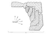
图8示出一个实施例,其中图4A的功能表面从一个通道移动到额外的拱顶; Figure 8 shows an embodiment in which the functional surface of Figure 4A is moved from one channel to an additional vault;
图9A-B示出根据一个实施例中继透镜如何被功能性地引入到光学通道的表面; 9A-B illustrate how a relay lens is functionally introduced into the surface of an optical channel according to one embodiment;
图10示出根据本发明实施例适于以大于90度的角度成像的形成光学通道的光线导向件; 10 illustrates a light guide forming an optical channel adapted to image at angles greater than 90 degrees in accordance with an embodiment of the present invention;
图11示出根据本发明实施例的圆形对称光线导向配置的90度断面; Figure 11 shows a 90 degree cross-section of a circular symmetric light guide arrangement according to an embodiment of the invention;
图12示出根据本发明实施例仅由三个光线导向件制成并形成四个光学通道的简单照明器的截面图; Figure 12 shows a cross-sectional view of a simple illuminator made of only three light guides and forming four optical channels according to an embodiment of the invention;
图13是示出光源和拱顶之间的空气隙以管理入射到光线导向件的角度的实施例; Figure 13 is an embodiment showing an air gap between the light source and the dome to manage the angle of incidence to the light guide;
图14A-D示出各种实施例用于放大目的,并倒转了光方向; Figures 14A-D illustrate various embodiments for magnification purposes, with light direction reversed;
图15A-C是适于在显微镜中使用的本发明的两个实施例的示意图; 15A-C are schematic diagrams of two embodiments of the invention suitable for use in a microscope;
图16是根据本发明一个实施例建立的模型; Fig. 16 is a model established according to one embodiment of the present invention;
图17A-B是照明强度图形,示出从根据本发明的实施例建立的模型的线性均匀照明; 17A-B are illumination intensity graphs showing linear uniform illumination from models built in accordance with embodiments of the present invention;
图18示出本发明一个实施例的横截切面; Figure 18 shows a cross-sectional section of an embodiment of the present invention;
图19示出具有光线矢量的旋转轴; Figure 19 shows the axis of rotation with the ray vector;
图20示出光源和照明(出射)光瞳;以及 Figure 20 shows the light source and illumination (exit) pupil; and
图21示出根据本发明一个实施例的光线路径。 Fig. 21 shows light paths according to one embodiment of the present invention. the
具体实施方式Detailed ways
本发明的一个实施例用作为LED照明器,该照明器特别用作小型LED投影仪中的组元。本发明的实施例提供下列优势中的一种或多种。 One embodiment of the present invention is used as an LED illuminator, particularly as a component in a small LED projector. Embodiments of the invention provide one or more of the following advantages. the
1.照明器组元具有良好的效率,也就是,照明效率大于50%,甚至可以大于80%(光谱透射效率)。 1. The illuminator component has good efficiency, that is, the lighting efficiency is greater than 50%, and can even be greater than 80% (spectral transmission efficiency). the
2.照明非常均匀且为矩形,因此不需要(但是可以使用)单独的光束均化器组元,例如复眼透镜。 2. The illumination is very uniform and rectangular, so a separate beam homogenizer component such as a fly-eye lens is not required (but can be used). the
3.照明器组元具有这样的优势,它即使在光源如同许多高亮度LED芯片一样被封入更高折射率的材料的情况下,也能够在很小的空间内从光源(LED)附近的整个半球收集光。当设计用于非封入的光源时,照明器组元不需要任何光学表面紧邻光源,这在一些应用中也是一项很重要的优势(对于热问题和材料的选择)。 3. The illuminator component has the advantage that it can illuminate from the entire vicinity of the light source (LED) in a small space even when the light source is enclosed in a higher refractive index material like many high-brightness LED chips. The hemisphere collects light. When designed for non-enclosed light sources, the illuminator components do not require any optical surfaces in close proximity to the light source, which is also an important advantage in some applications (with respect to thermal issues and material choice). the
通过以有益的方式利用光源的形状,照明器组元还执行光束成形,也就是说,照明的形状就是光源的形状。 By exploiting the shape of the light source in an advantageous manner, the illuminator component also performs beam shaping, that is to say the shape of the illumination is the shape of the light source. the
4.照明的展度可保持在光源的原始展度的140%以下,甚至在光源的原始展度的105%以下。 4. The etendue of the illumination can be kept below 140% of the original etendue of the light source, even below 105% of the original etendue of the light source. the
5.照明器组元的尺寸非常紧凑。该组元的直径由展度定律确定,该照明器组元的高度通常为直径的一半。下面给出具体的尺寸实例。 5. The size of the illuminator components is very compact. The diameter of the component is determined by the law of spread, and the height of the illuminator component is usually half the diameter. Specific size examples are given below. the
6.照明器组元具有圆形外形,这使得能够与小型LED投影仪应用中的投影透镜良好匹配。这也使得光学引擎的总体尺寸非常小。 6. The illuminator component has a circular shape, which enables a good match with projection lenses in small LED projector applications. This also makes the overall size of the optical engine very small. the
7.照明器组元的输出光束可以是非常远心的,意味着可以在照明器组元之上使用偏振循环片以增加LCD或LCoS投影仪应用的效率。 7. The output beam of the illuminator component can be very telecentric, meaning that a polarization recycling plate can be used on top of the illuminator component to increase the efficiency of LCD or LCoS projector applications. the
8.照明器组元所形成的均匀远心光束可用在宽泛的各种光学结构和应 用中。 8. The uniform telecentric light beam formed by the illuminator components can be used in a wide variety of optical structures and applications. the
9.照明器组元可通过注塑成型批量生产。模具可通过例如金刚石车削或精密NC加工而制成。 9. Illuminator components can be mass-produced by injection molding. The mold can be made by eg diamond turning or precision NC machining. the
10.除了小型LED投影仪之外,照明器组元可用在宽泛的各种不同应用中,例如包括相机闪光灯、显微镜和平视显示器。 10. In addition to small LED projectors, the illuminator components can be used in a wide variety of different applications including, for example, camera flashes, microscopes, and head-up displays. the
考虑将平面物体成像到离物体距离L的共面图像上的成像器。光轴收集物体和图像的中心点,并且光轴垂直于物体平面和图像平面。成像的放大率M是图像高度与物体高度的比例。靠近光轴,成像器包括将物体成像为图像的一个或多个透镜。这样的透镜对相对光轴以相对小角度入射的光进行作用。可利用常规透镜设计原理来设计上述透镜。例如,可以使用离物体距离为R=L/(M+1)定位的焦距为f=ML/(M+1)2的非球面透镜。这是常规的。本发明的成像通道的实施例对离光轴大角度的光进行收集和操作。这可以是对小角度操作的常规透镜的补充,因此根据成像器的实施例,照明器或会聚器包括下面详述的一个或多个成像通道。 Consider an imager that images a planar object onto a coplanar image at a distance L from the object. The optical axis collects the center point of the object and the image, and the optical axis is perpendicular to the object plane and the image plane. The imaging magnification M is the ratio of the image height to the object height. Near the optical axis, an imager includes one or more lenses that image an object into an image. Such lenses act on light incident at relatively small angles to the optical axis. The lenses described above can be designed using conventional lens design principles. For example, an aspheric lens with a focal length f=ML/(M+1)2 located at a distance R=L/(M+1) from the object may be used. This is routine. Embodiments of the imaging channel of the present invention collect and manipulate light at large angles from the optical axis. This may be in addition to conventional lenses operating at small angles, so depending on the embodiment of the imager, the illuminator or converger includes one or more of the imaging channels detailed below.
下面的描述是在光源为发光二极管LED的情景下。由于其低功率要求和低热输出以及对特定颜色实施的适应性,对于这里描述的多种照明应用,上述光源被认为是高度有利的光源(参见例如引入的共有美国专利No.7,059,728),但是这并不是本发明的限制因素;LED作为光源只是用于本发明实施例的一种扩展光源的示例。其他光源包括有机LED,光子晶体LED,光子晶格LED,谐振腔LED,激光器,弧光灯,灯泡,光纤等等。本发明的使用并不局限于产生光的组元,而是该情景下的光源同样可理解为例如是发射、反射或散射光的任何物体,或者可以是光源的像或者虚像。 The following description is under the scenario that the light source is a light emitting diode LED. Due to their low power requirements and low heat output and adaptability to specific color implementations, the aforementioned light sources are considered highly advantageous light sources for many of the lighting applications described herein (see, e.g., incorporated co-owned U.S. Patent No. 7,059,728), but this It is not a limiting factor of the invention; LEDs as light sources are merely an example of an extended light source for embodiments of the invention. Other light sources include organic LEDs, photonic crystal LEDs, photonic lattice LEDs, resonant cavity LEDs, lasers, arc lamps, light bulbs, fiber optics, and more. The use of the invention is not limited to light-generating components, but a light source in this context is equally understood to be, for example, any object that emits, reflects or scatters light, or may be an image or a virtual image of the light source. the
现货供应的LED封装包括衬底上安装的LED芯片,该LED芯片是实际的发光半导体芯片。除此之外,高效LED芯片可封入在拱顶形外壳之内,所述外壳填充有折射率大于空气(大于1)的光透射材料。 Off-the-shelf LED packages include a substrate-mounted LED chip, which is the actual light-emitting semiconductor chip. Additionally, high-efficiency LED chips can be enclosed within a dome-shaped housing filled with a light-transmissive material with a refractive index greater than that of air (greater than 1). the
出于本说明的目的,考虑LED芯片为矩形的,并仅仅辐射到半球中(有效面积实际上辐射到整个球中,但是典型地在LED芯片下面有一个镜面表面,因此辐射被粗略限制到仅仅一个半球)。假定期望的照明形状是矩形 的,如同大多数光学数据投影的情况(例如,电视、计算机屏幕、诸如MP3播放器和手机之类的手持设备的屏幕)。该矩形形状可以例如是正方的,或者是通用的4∶3或16∶9的纵横比的矩形。为了全面优化光学引擎的尺寸,LED芯片和期望照明的形状应该优选为相似的。因此,在期望具有最小尺寸的光学引擎时,例如旨在照明16∶9的纵横比的光学引擎优选包括16∶9纵横比的LED芯片作为其光源。 For the purposes of this description, consider the LED chip to be rectangular and radiate only into the hemisphere (the active area actually radiates into the entire sphere, but typically there is a specular surface underneath the LED chip so the radiation is roughly limited to only one hemisphere). It is assumed that the desired illumination shape is rectangular, as is the case with most optical data projections (e.g., televisions, computer screens, screens of handheld devices such as MP3 players and cell phones). The rectangular shape may be, for example, square, or a rectangle with a common aspect ratio of 4:3 or 16:9. In order to fully optimize the size of the optical engine, the shape of the LED chip and the desired illumination should preferably be similar. Thus, where an optical engine with minimal dimensions is desired, for example an optical engine intended to illuminate a 16:9 aspect ratio preferably comprises a 16:9 aspect ratio LED chip as its light source. the
解决利用离光轴相对较大角度的光进行成像这一问题的一个重要课题是适当处理这样的问题:怎样修改LED辐射图形从而获得这样一个圆形区域,从该区域内的每个位置以相似的一致直角锥辐射。这在图2A中进行图示。一个重要的设计考虑是,照明的展度,也就是ΩA,应该尽可能接近LED芯片的原始展度。 An important issue in solving the problem of imaging with light at relatively large angles from the optical axis is to properly deal with the problem of how to modify the LED radiation pattern so as to obtain such a circular area from each position in the area with similar A uniform right-angle cone of radiation. This is illustrated in Figure 2A. An important design consideration is that the etendue of the illumination, ΩA, should be as close as possible to the native etendue of the LED chip. the
本文详述的方案是基于接下来描述的发现。图2B示出在用公式表示数学解中使用到的一些尺寸和常数。令z轴为光轴20。在xy平面内(垂直于z轴)的圆坐标由半径r和角度α定义。到光轴20的角度由θ表示。假设一个矩形Lambertian光源22(例如,LED芯片),并将其置于xy平面上,使得其中心点位于原点。让我们假定在LED芯片下面有一个镜面,由此仅需要收集射向LED芯片之上的上半球的光。现在以中心在原点的半径为R的表面S(24)构造一个半球。圆形区域U(26)平行于xy平面,其半径为R,中心在离圆心至少距离R的z轴上。(在图2B中距离为R,但是该距离也可以更大)。现在,考虑圆形区域U内的一个微小的任意面元dU(28),该面元由圆形坐标α1,α2,r1,以及r2限定。现在将面元dU(28)沿z轴投影到半球S的表面上,从而限定另一个面元dS(29)。 The protocol detailed here is based on the findings described next. Figure 2B shows some of the dimensions and constants used in formulating the mathematical solution. Let the z-axis be the
现在,我们假定对在面元dU(28)内均匀的、到达面元dS(29)的光进行变换。当我们在整个表面U(26)上进行这种变换时,我们对从LED芯片到达半球的区域U(26)上的所有光进行了变换。然而,同时我们将会获得我们想要的照明:在整个区域U(26)上的相似均匀照明图形。区域U(26)上的光束将具有与光源相同的展度。 Now, we assume that the light arriving at bin dS(29), which is uniform within bin dU(28), is transformed. When we do this transformation over the entire surface U(26), we transform all the light from the LED chip to the area U(26) that reaches the hemisphere. However, at the same time we will get the lighting we want: a similar uniform lighting pattern over the whole area U(26). The beam on area U (26) will have the same etendue as the source. the
接下来的问题是,怎样在仍然有制造效率的组元中实施上述构想。精 确变换将需要极其复杂的结构,然而我们可以对期望的变换进行近似仍然获得很好的结果。 The next question is how to implement the above ideas in components that are still productive. Exact transformations would require extremely complex structures, however we can approximate the desired transformation and still get good results. the
接近光轴,也就是,当角度θ接近零时,期望的变换已经固有地完成,也就是,不需要均衡任何光。 Close to the optical axis, that is, when the angle θ is close to zero, the desired transformation is already inherently accomplished, that is, there is no need to equalize any light. the
在小角度θ下,解决方案很简单:透镜表面将会进行很好的变换。例如,如果LED封入在具有折射率n=1.5的材料中,那么其曲率半径约为R/2,曲率中心位于光轴处且距离LED芯片大约R/2的距离的透镜表面将会形成期望的光输出图形,如图2C中最靠近光轴z(20)的两个投影所示。表面的精确形状可以利用光学设计软件进行设计。在仅需要一个表面时,最好的形状典型为非球面。 At small angles θ, the solution is simple: the lens surface will be well transformed. For example, if the LED is encapsulated in a material with a refractive index n=1.5, then a lens surface with a radius of curvature of approximately R/2 centered at the optical axis and a distance of approximately R/2 from the LED chip will form the desired The light output pattern is shown in Figure 2C for the two projections closest to the optical axis z(20). The precise shape of the surface can be designed using optical design software. When only one surface is required, the best shape is typically aspherical. the
然而,如图2C中可见,随着θ的增加,透镜表面30更加靠近芯片,因此光束的光锥32变得大于从更靠近光轴20的小角度θ发射的光束的对应光锥34,照明(也就是,照明强度)不再均匀。另外,从更大θ角度产生的这些锥形投影34相对理想矩形的畸变变得更加严重。最后,在大θ角度下,例如当θ接近约45度时,光变得从透镜表面30全内反射TIR36。尽管如此,透镜对于小θ角度仍然实现良好的变换。 However, as can be seen in Figure 2C, as θ increases, the
根据所需照明的质量,使用透镜作为良好近似的最大θ角可以通过使用类似菲涅耳透镜的结构38而扩展到例如最高至约40度,如图2D所示。菲涅耳透镜结构具有这样的优势:由于表面高度和角度并没有如光滑透镜类似表面那样强地约束在一起,因此可以改善照明均匀性和图像畸变。缺点是有可能损失光,并增加表面方向的不连续中的展度。 Depending on the quality of illumination required, the maximum theta angle using lenses as a good approximation can be extended, for example, up to about 40 degrees by using a Fresnel lens-
当然,可以使用若干光学表面取代仅一个表面,例如如图2E中所示的两个或更多个透镜。然而,当θ进一步增加远离光轴20时,这些透镜解决方案开始具有与上述相似的问题。 Of course, instead of just one surface, several optical surfaces could be used, such as two or more lenses as shown in Figure 2E. However, as Θ increases further away from the
在不能使用以上提到的透镜或菲涅耳透镜类似结构38的中间θ角度附近(也就是,例如接近45度),可以通过例如图3中所示的镜面或折反射结构近似期望的变换,所述折反射结构包括第一折射面302,镜面304和第二折射面306。镜面304可以是基于TIR的表面或者是镜面涂布表面。 In the vicinity of intermediate theta angles (i.e., e.g., near 45 degrees) where the above-mentioned lens or Fresnel lens-
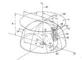
对于更大的θ角度,可以根据这些内容使用形成“成像通道”的一个或多个结构来完成变换。这样的成像通道圆柱对称的。图4A中示出一个示例性成像通道的横截面。 For larger theta angles, transformations can be accomplished using one or more structures forming an "imaging channel" according to these contexts. Such imaging channels are cylindrically symmetric. A cross-section of an exemplary imaging channel is shown in Figure 4A. the
示出的成像通道包括:两个分立的圆柱对称组元即光线导向件40,42,所述成像通道限定类似环面的表面T1,T2,T3和T4;镜面M;以及被认为是侧表面的其他表面。将镜面光线导向件40考虑作为第一光线导向件,将非镜面的42作为第二光线导向件。如从光线追踪中可见的,第一40和第二42光线导向件彼此处于一个光学序列中。如图4A中的光线轨迹可见,表面T1形成来自LED 22的光的入射光瞳(也就是,通道输入),如图4A中的发射光线可见,表面T4形成进入入射光瞳T1的光的出射光瞳(也就是,通道输出)。在该示例性成像通道中,该入射光瞳接受从LED 22以大约40度角度发射的光(若从光轴20测量,该角度更大)。如将会看到的,该成像通道可适于以更接近的角度成像,但是用于更大角度的图4A的布置解决了在设计总体光学引擎中更为困难的问题。表面T1,T2,T3,T4,和M为类似环面的表面,在切线方向不具有成像能力,但是当观察横截平面时,我们可以讨论该横截平面中的成像。我们描述的横截面和光轴20都位于该平面中,该平面在图4A中即为页面本身。光线导向件40,42本身为环形形状,如同示出的横截面视图绕旋转轴20旋转以限定所述光线导向件40,42的外表面一样。在任意横截平面中,表面T1将来自LED芯片的光通过全内反射镜面M成像为近似在表面T2和T3之间的中间图像。表面T2和T3共同将表面T1成像到表面T4上。最后,表面T4将中间图像成像为无穷大,并形成矩形远心照明图形。换句话说,在径向(也就是,在任意横截平面中)形成期望的变换。这可能是粗略的,因为例如表面T1可能并不是严格沿着半球表面S。另外,由于Lambertian余弦定理,穿越表面T1的照明可能并不均匀。然而,这是一种很好的近似,并且能够提供足够好的期望变换。如果光线导向件40,42很狭窄,那么变换更为精确,但是制造光线导向件40,42变得更加困难。通过使用非球面横截表面优化成像通道的几何形状,有可能非常精确地实现期望的变换。 The illustrated imaging channel comprises: two discrete cylindrically symmetric components, namely light guides 40, 42, which define torus-like surfacesT1 ,T2 ,T3 andT4 ; a mirror M; Other surfaces considered to be side surfaces. Consider the specular
在切线方向,由于圆柱对称,粗略形成期望的变换。在切线方向,由成像通道的输入侧(入射光瞳,图4A中的T1)和输出侧(出射光瞳,图4A中的T4)离光轴的距离限定角度放大率。这是由于光学组元的圆柱对称性,其结果是每个光线的偏斜都是不变的。偏斜是光线离光轴20的距离和光线的切线分量的乘积。由于通道的入射和出射光瞳距离光轴相等的距离(平均上),因此出射光瞳处的切线分量与入射光瞳处的相等,这意味着形成了期望的变换。本发明的该内容在这里被称为相等半径规则。 In the tangential direction, due to cylindrical symmetry, roughly forms the desired transformation. In the tangential direction, the angular magnification is defined by the distance from the optical axis on the input side (entrance pupil, T1 in FIG. 4A ) and output side (exit pupil, T4 in FIG. 4A ) of the imaging channel. This is due to the cylindrical symmetry of the optical components, which results in a constant deflection for each ray. Skew is the product of the distance of the ray from the
来自LED 22的特定光线可通过全内反射从侧表面反射,这将重新获得否则就会损失的光。 Specific light from the
还存在执行相同功能的可能的其他成像通道结构。例如,如果在一些几何情况下不能使用全内反射,可以将镜面M进行镜面涂布。镜面M可以在表面T3和T4之间,而不是表面T1和T2之间。镜面M还可以位于表面T2和T3之间(例如,如果两个光线导向件都具有与第二光线导向件42相似的横截面,并且镜面没有引入到光线导向件之一中,而是设置于其间),并且可以通过镜面涂布一个独立组元或在所讨论的成像通道附近的成像通道的一部分,或者通过使用例如具有棱柱形状横截面的独立组元而形成所述镜面M。 There are also possible other imaging channel configurations that perform the same function. For example, if total internal reflection cannot be used in some geometry, the mirror surface M can be mirror coated. Mirror M may be between surfacesT3 andT4 instead of between surfacesT1 andT2 . The mirror M can also be located between the surfacesT2 andT3 (for example, if both light guides have a similar cross-section as the second
成像通道的使用并不仅仅局限于较大的θ角度,也就是在形成离光轴大角度的方向,它们还可以以有益的方式用于更靠近光轴的情况。如果区域U26距离原点的距离h基本大于半球S 24的半径R,将很难在中心(靠近光轴)使用透镜类似结构38,因为张开角度要求与透镜表面位置要求不符合。在这种情况下,有可能使用中心区域没有镜面的成像通道结构,如图4B所示。在图4B中,两个光线导向件44,46以横截面示出,并配置为跨越光轴20。两个光线导向件形成不具有镜面M的四个成像通道A,B,C,D(沿虚线偏移)。这些光线导向件44,46具有与图4A所详细示出的表面并无不同的成像表面,但是由于它们从更靠近光轴20的角度接受入射光,因此并不需要镜面M。光线路径401,402,403,404示出在横截平面中成像通道C的成像功能。这示出可以更靠近轴使用的成像通道的一个实施例。 The use of imaging channels is not limited only to larger θ angles, that is, in directions forming large angles from the optical axis, they can also be used in a beneficial manner closer to the optical axis. If the distance h of the region U26 from the origin is substantially greater than the radius R of the hemisphere S24, it will be difficult to use the lens-
注意到,以上描述的具有镜面的成像通道形成光源的镜面像,如同透镜或菲涅耳透镜系统靠近光轴一样。在切线方向,只能在成像通道中形成光源22的镜面像。然而,以上描述的不具有镜面的成像通道在横截平面中形成光源22的不是镜面像的像。因此不具有镜面的通道并不形成光源的像,除非该光源是基本轴对称的。因此,这样的通道特别地适合用于利用基本轴对称的光源用于照明目的。然而,如果期望一定量的不成像用于平滑光源的像以用于例如照明的目的,那么这样的通道也可用于非轴对称的光源,例如矩形光源。 Note that the imaging channels described above with mirrors form a mirror image of the light source, as do lenses or Fresnel lens systems close to the optical axis. In the tangential direction, only a mirror image of the
照明器的一个实施例使用具有镜面的成像通道和不具有镜面的成像通道两者。这样的照明器在径向方向形成光源的镜面像和非镜面像两者,并且这些像在像平面上(出射光瞳之外)位于彼此顶上。相比于对光源直接成像所获得的照明,这样的照明器可用于从光源产生更加均匀的照明。 One embodiment of the illuminator uses both imaging channels with and without mirrors. Such illuminators form both specular and non-specular images of the light source in radial direction, and these images lie on top of each other on the image plane (outside the exit pupil). Such illuminators can be used to produce more uniform illumination from a light source than would be obtained by directly imaging the light source. the
有可能以多种方式对呈现的通道结构进行修改,使得创新构想是相同的。单个功能表面可以实施为若干表面,或者若干功能表面可以实施为一个表面,只要形成上述创新构想和期望的变换。一些体积(例如,T2和T3之间)可以用材料填充,但也可以是空气,一些空气间隙可以改变为一些透射材料。有可能以各种不同方式执行多种上述的光学功能,例如可以使用衍射光学元件或光子晶体或晶格代替折射和/或反射光学元件。也可以改变各种光线导向件和组元的材料和折射率。可以对表面进行抗反射或高反射涂布用以提高性能。因此,这里示出的配置并不限制本发明的范围。 It is possible to modify the presented channel structure in many ways such that the innovative idea is the same. A single functional surface can be implemented as several surfaces, or several functional surfaces can be implemented as one surface, as long as the above-mentioned innovative ideas and desired transformations are formed. Some volumes (eg, betweenT2 andT3 ) can be filled with material, but also air, and some air gaps can be changed to some transmissive material. It is possible to perform many of the above-mentioned optical functions in various ways, for example diffractive optical elements or photonic crystals or lattices may be used instead of refractive and/or reflective optical elements. The materials and indices of refraction of the various light guides and components can also be varied. Surfaces can be antireflective or highly reflective coated for enhanced performance. Therefore, the configurations shown here do not limit the scope of the present invention.
图4C,4D,4E,4F和4G示出成像通道的一些其他示例性实施例。 Figures 4C, 4D, 4E, 4F and 4G illustrate some other exemplary embodiments of imaging channels. the
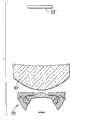
图4C示出与图4A中呈现的相同的结构,但是具有的LED芯片22封入到透射拱顶50之内。注意到,取代于将LED芯片成像为中间图像(在横截平面处)的一个表面,这里存在两个表面:拱顶表面53和下光线导向件40的下表面,并且如果镜面M具有任何的光焦度(因为它也可以具有),还可以有三个表面。 FIG. 4C shows the same structure as presented in FIG. 4A , but with the
图4D示出与图4C相同的成像通道结构,但是其中上(第二)光线导向件42的功能通过下述方式实现:使得下(第一)光线导向件40的上表 面T2’上的曲率更强(也就是,图4C的表面T2和T3由具有T2和T3共同光焦度的仅仅一个表面T2’代替),以及具有两个表面代替一个表面T4、用于将中间图像成像为图像(在横截平面中)的环形透镜408。 Fig. 4D shows the same imaging channel structure as Fig. 4C, but wherein the function of the upper (second)
图4E示出具有镜面M的另一个成像通道,其中表面T1与拱顶50一体形成,TIR镜面用单独的圆柱对称镜面组元408代替。 FIG. 4E shows another imaging channel with a mirror M, where the surface T1 is integrally formed with the
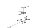
图4F示出具有镜面的又一成像通道,其中表面T1和T4由环形透镜410,412代替,表面T2和T3由一个环形透镜414代替,镜面由单独的圆柱对称镜面组元408代替。 Figure 4F shows yet another imaging channel with mirrors, wherein surfacesT1 andT4 are replaced by
图4G示出具有镜面的又一成像通道,其中表面T1,T2,T3和T4由圆柱对称表面416,418,420,422代替,这些圆柱对称表面具有平面的横截面,包含微光学特征,诸如衍射光学结构或小尺度菲涅耳透镜结构。镜面由单独的圆柱对称镜面组元408代替。 FIG. 4G shows yet another imaging channel with mirrors, wherein surfaces T1 , T2 , T3 and T4 are replaced by cylindrically
通过将上述成像通道或其变体与靠近光轴的例如透镜、菲涅耳透镜或反折射结构结合在一起,有可能对绕光源22的整个半球以足够的精确度进行期望的变换。由于成像通道可以以各种不同实施例来实现,有可能选择这样的实现方式,使得通过将一些组元一体形成而简化制造阶段。这也是本发明的优势。环形透镜、菲涅耳透镜、反折射结构或者具有微光学或衍射光学结构的组元都可以被称为光线导向件,因为它们都对光线进行导向。因此,光线导向件的概念并不局限于以上例子中示出的结构,而是应该将其理解为对光线进行导向,也就是,改变至少一些光线的传播方向的任何组元或组元的部分。图5A-5E示出诸如图4A中示出的成像通道,这些成像通道在Luxeon K2 LED封装上设置在一起作为LED照明器。 By combining the imaging channels described above or variants thereof with eg lenses, Fresnel lenses or catadioptric structures close to the optical axis, it is possible to perform the desired transformation with sufficient accuracy for the entire hemisphere around the
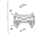
图5A示出具有毫米尺寸的LED照明器的实施例,其中具有菲涅耳透镜和两个成像通道,所述透镜靠近轴,并被以上描述的反折射镜面结构和两个成像通道包围。所述两个通道的上部一体形成到一个光线导向件42中用以使得制造更加容易。组元的部分设计用于光学级PMMA塑料。 Figure 5A shows an embodiment of a millimeter-sized LED illuminator with a Fresnel lens close to the axis and surrounded by the catadioptric mirror structure and two imaging channels described above. The upper parts of the two channels are integrated into a
图5B示出同样的LED照明器的3维视图,示出组元的圆形对称。 Figure 5B shows a 3-dimensional view of the same LED illuminator showing the circular symmetry of the components. the
图5C示出同样的LED照明器的横截切面。 Figure 5C shows a cross-sectional section of the same LED illuminator. the
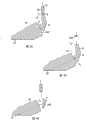
换言之,图5A示出使用与衬底的镜面隔开的商用LED芯片(Luxeon K2)的本发明LED照明器的实施例的示意性截面视图。在横截面40,42,46中示出四个不同的光线导向件(结构),第三光线导向件48原则上与第一光学光线导向件40相似地操作,但是由于其位置在第一光线导向件40内侧,适用于稍微不同的光入射角度。第二光线导向件42被显示为一个组元,但是可以由独立的多个部分制成以将来自第一光线导向件40和第三光线导向件48两者的光独立地“成像”。光线导向件40,42,46,48可以是一体结构。LED 22装入安装到镜面52的光透射拱顶50的一侧。尽管测量的是几毫米,但是实施例可以在测量基础上成比例地扩展/缩减。图5B示出各种通道和总体组元的圆形对称,图5C是图5B的截面视图,示出LED封装22的设置。电引线54对LED芯片22供电。 In other words, Figure 5A shows a schematic cross-sectional view of an embodiment of an inventive LED luminaire using a commercial LED chip (Luxeon K2) spaced apart from the mirror surface of the substrate. Four different light guides (structures) are shown in
图5D示出本发明LED照明器的另一实例。该照明器包括靠近轴的菲涅耳透镜、反折射镜面结构502以及三个成像通道A,B和C。成像通道的上部501与菲涅耳透镜部分和反折射镜面结构502一体形成为一个组元46/42以使得制造简单。成像通道A的下部分是一个分立的光线导向件组元49。注意到,第二光线导向件42在一个实施例中可适于包括这样的中心透镜从而跨越光轴20,如图5D中46/42所示出。在这种情况下,第二光线导向件42不再是环形的,而是对于多个通道在更靠近其外侧的部分作用以穿过成像表面T3和T4成像,其中与基本如上所述的第一环形光线导向件40,第三环形光线导向件48和第四环形光线导向件49中的每一个的成像表面T2相交。 Fig. 5D shows another example of the LED illuminator of the present invention. The illuminator includes a near-axis Fresnel lens, a
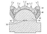
图5E示出LED照明器的另一实例,其具有靠近轴的菲涅耳透镜和进一步远离轴20的三个成像通道A,B和C。最中心的通道A的下部分504与菲涅耳部分一体形成,所有三个通道的上部一体形成为一个光线导向件42。注意到,每个通道A,B和C的镜面MA,MB和MC具有弯曲形状,也就是,参与将通道的入射光瞳成像到中间图像,所述中间图像大致位于通道的下部504,48,40和上部42之间。 FIG. 5E shows another example of an LED illuminator with a Fresnel lens close to the axis and three imaging channels A, B and C further away from the
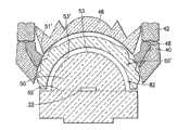
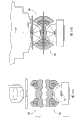
图6A示出按比例(单位是毫米)的另一照明器的横截面。图6B示出 具有拱顶50的、LED芯片22之上的同样照明器的透视图。该照明器具有靠近轴的透镜,其后有不具有镜面的三个成像通道D,E和F,以及具有镜面MA,MB和MC的三个成像通道A,B和C。整个照明器仅仅包含四部分,这四部分可以经济高效地进行批量制造。组元还具有支撑物和用于组装目的的对准特征。图6B示出图6A的照明器58的透视图。第三光线导向件48具有与第一光学通道40所描述的不同的入射光瞳和第二表面。如可见的,进入第三光线导向件48的入射光瞳的基本所有光都通过该第三光线导向件48,并通过其上表面T2朝向第二光线导向件42的下表面T3重新定向。另一光线导向件46是一个组合,在外侧边沿,其形成光学通道的一部分,在最靠近光轴20的中心区域,它是一个常规的透镜结构。如可见的,通道部分和透镜的各种组合可以被组合为单体制造组元或被分开为若干这样的组元。 Figure 6A shows a cross-section of another illuminator to scale (in millimeters). Figure 6B shows a perspective view of the same luminaire with
图6C示出具有光线轨迹的图6A-B的最中心成像通道D的径向横截面。该通道具有四个导向表面(除了拱顶50之外,拱顶50可以认为是通道的一部分或者不依赖于光源的定义),上述导向表面在每个径向横截平面中将光源22的镜面像基本形成到无穷远,并且其在切线方向将光源的非镜面像形成到无穷远。光线示出在径向横截平面中的成像。第一表面T1基本将LED芯片22成像为中间图像604,该中间图像604接着被表面T4成像到无穷远。表面T2和T3基本将通道的入射光瞳602成像到通道C的出射光瞳608。第一到第四的所有表面都是非球面,也就是,横截面不是圆弧。非球面表面在设计优化中比圆弧面给出更大的自由度,因此在设计限制之内提供更好的性能,例如可制造性和成本方面。 Figure 6C shows a radial cross-section of the centermost imaging channel D of Figures 6A-B with ray traces. The channel has four guide surfaces (except for the
图6D示出具有光线轨迹的图6A-B的最外面成像通道C的径向横截面。通道C具有五个导向表面(除了拱顶之外),上述导向表面将光源的镜面像基本形成到无穷远。第一表面T1和镜面M将LED芯片基本成像为中间图像604,该中间图像604接着被表面T4成像到无穷远。表面T2和T3基本将通道的入射光瞳602成像到通道的出射光瞳608。镜面M通过全内反射反射光线。所有这五个表面都是非球面的。 Figure 6D shows a radial cross-section of the outermost imaging channel C of Figures 6A-B with ray traces. Channel C has five guide surfaces (except the dome) which form a mirror image of the light source substantially to infinity. The first surface T1 and the mirror M essentially image the LED chip into an
图6E是图6B的分解视图,示出外壳56,在外壳56中设置了图6E中示出的照明器的各部分。注意到,当如图所示进行组装时,附加的光学通道的部分(其在中心部分处为透镜类型结构46)挨着透镜在该透镜外侧具有成像通道结构的下部分610。 FIG. 6E is an exploded view of FIG.
如可见的,通道和透镜的各种组合可以被组合为单体制造组元或被分开为若干这样的组元。 As can be seen, various combinations of channels and lenses can be combined as a single fabricated component or separated into several such components. the
图7A示出在图2A-B的数学构建的背景下完成的装置58。沿光轴来自LED光源22的光从离光轴较大的角度(例如,如将示出的40-90度,或者40-140度,或更具体为45-90度)被重新定向到大致平行于光轴20的平均方向。另外,从矩形LED芯片22输出的中心对称照明被转换为基本线性均匀照明,如图7A的光锥59所示。照明器输出平面702的每一个点具有相似的矩形照明光锥59。线性均匀角度分布图形由角度θx,θy限定,其表示线性光锥59在x和y方向的半开角。如果光源22不是矩形的,而是例如圆形或者三角形的,照明光锥59将具有相应的形状。 Figure 7A shows the
以上详述的照明器58具有空间上圆形的输出光发射区域,这确保与投影透镜的良好光瞳匹配。理想地,照明器将位于投影光学引擎的照明光瞳中。现在,令照明器输出的直径为D。矩形光“锥”59由角度α限定,如图7B所示。照明器的设计允许调节输出直径D和光锥59角度α。对于一定尺寸的光源22,根据展度定律,D反比于彼此(见美国专利No.7,059,728)。在本发明一个实施例中,光源是具有0.93mmx0.93mmx0.1mm的尺寸的矩形LED芯片22,直径D为7.5mm,收集的立体角具有80度的半角,α为10.7度。对于D没有上限,但是如上所述,其优选为将光学引擎的尺寸最小化。 The
总体来说,本发明的构建实施例符合图7C的相对比例,邻近表面T4的照明器输出平面702的直径约为LED 22和该输出平面702之间的距离h的两倍。因此,在这样的空间内进行光收集和光束成形,所述空间的直径根据展度定律由光束的期望半开角确定,其在光源22之上的高度约为直径的一半,如图7C中所示。不过,高度还可以更长。 In general, the constructed embodiment of the invention conforms to the relative scale of FIG. 7C , with the diameter of the
图7D示出照明器怎样在投影光学引擎中用于照明。在LED芯片22,光束在空间上为线性,因为这是芯片本身的形状,但是在角度上来自其的照明是圆形的。照明器58将这样的分布倒转,使得照明器58的输出在空间上为圆形,但是照明角度分布为线性均匀的,如下面的强度图所示。在小型显示屏72处,照明区域的空间分布是线性的,但是角度分布为圆形。这与空间上为圆形的透镜74的入射光瞳完美相符。因此,照明器58为投影引擎提供一种解决方案,其中整个系统的光瞳都相符。 Figure 7D shows how an illuminator is used for illumination in a projection light engine. At the
成像通道概念提供了多种优势。通过在需要时等比例缩放上述设计,同样的设计可用于不同形状和尺寸的LED芯片22。同样的设计还可用于围绕LED芯片的不同尺寸的拱顶50。 The imaging channel concept offers several advantages. The same design can be used for
现有LED封装中LED芯片22和拱顶50之间的对准可能非常不精确,以至于如果不通过照明器内的LED精确对准进行补偿就会影响照明器58的性能。另一种解决方案是围绕现有LED拱顶50使用额外的(第二)拱顶50’,并在其之间使用折射率匹配凝胶或胶质82以避免LED芯片对准问题。额外的拱顶50’可精确对准到LED芯片或封装。使用该额外的拱顶50’的另一原因是使用了具有比原始设计更小的LED拱顶50的同样的LED照明器58。 The alignment between the
通道的数目可以在从一到几十之间变化,对于更大外形的设备甚至可以更多。通道越多,矩形照明越精确,但是代价是制造越困难。然而,通过适当优化通道设计,并通过使用如上所述的非球面表面,有可能获得基本精确的成像功能。 The number of channels can vary from one to several tens, and even more for larger form factor devices. The more channels, the more accurate the lighting of the rectangle, but at the cost of being more difficult to manufacture. However, by properly optimizing the channel design, and by using aspheric surfaces as described above, it is possible to obtain substantially precise imaging capabilities. the
此外,如果在现有LED拱顶50周围使用额外的拱顶50’(其形成表面S),有可能将成像通道的第一表面T1的功能部分地或全部地引入到额外的拱顶50’的朝外表面51’,如图8所示。这里,额外的拱顶50’具有朝内表面53’,该表面与商用LED芯片22/拱顶50组合的表面53相匹配。折射率匹配凝胶或胶质82将两者粘合,使得来自LED 22的光被额外的拱顶50’的外表面51’操纵,从而允许更简单地制造在额外拱顶50’外周并与其相符的光线导向件40和48。注意到,在图8中那些光线导向件40,48的面向 额外拱顶50’及其朝外表面51’的表面比不具有额外拱顶50’的实施例(见图4A)的更为平面,因为功能化成形的表面T1在额外拱顶50’的朝外表面51’上。 Furthermore, if an additional dome 50' (which forms the surface S) is used around the existing
如果光学通道和总体照明器58设计用于远心输出,光锥59垂直于输出平面辐射(也就是,需要额外的中继透镜92来使得光锥在小型显示屏72处重合,如图9A所示)。通道和照明器58也可以设计用于非远心照明,由此不需要额外的透镜。中继透镜的功能可以并入到照明器58的最上面的表面,具体为通道的面向最外面的表面,如图9B所示。通道的最后一个表面T4可以被修改,使得光束朝向轴20倾斜,或者如期望地进一步远离轴20。在一些应用中,期望将该倾斜随着半径进行少许改变。这也可以通过修改光线导向件设计来实现。例如,可以在从照明器输出平面的中心朝向边沿移动的时候逐渐减小角度α。这在很低的光圈值/F制光圈系统中是有益的。这样的修改可以这样做出:稍微偏离以上描述的等半径规则,使得偏离是半径的函数,然而保持其他的原则不变。 If the optical channel and
有时候这样做是明智的,即,将组元设计和制造为具有远心输出,然后紧随该组元后面定位一个中继透镜92,用以将光束转换为非远心的,这样如果需要改变远心度,就仅需要改变中继透镜92,而不需要用其他不同设计来代替光线导向件或照明器58。如果需要将远心度调节为使得在不同的径向输出区域调节也是不同的,可以在紧随照明器之后使用一个单独的光线导向件,该光线导向件在每个区域具有适当的折射表面角度。可以通过例如金刚石切削来容易地制造这样的光线导向件。 Sometimes it is advisable to design and fabricate a component to have a telecentric output, then position a
如果光源是不均匀的,而希望获得均匀图像,则可以利用平滑效果,该效果通过为通道输出的不同区域设计不同的角“放大率”来使得照明更加均匀。此外我们可以在组元输出的不同区域不同地修改光束形状,这也可以用于使照明平滑。这些方法以增加展度或增加损耗为代价实施平滑,并偏离了精确成像的功能。 If the light source is non-uniform and you want a uniform image, you can take advantage of the smoothing effect, which makes the illumination more uniform by assigning different angular "magnifications" to different areas of the channel's output. Furthermore we can modify the beam shape differently in different regions of the component output, which can also be used to smooth the lighting. These methods implement smoothing at the expense of increased spread or increased loss, and deviate from the capabilities of accurate imaging. the
使照明平滑的一种方式是在照明器输出的特定或全部区域中沿径向和切线方向引入放大率差异。这仅仅在期望区域中将图像在切线上(也就是, 圆柱地)平滑期望的量。这也是以增加展度或损耗为代价。可以通过调整通道的入射和出射光瞳距离圆柱对称的光线导向件的旋转轴(20)的距离来调整切向放大率,也就是,有目的地偏离等半径规则。可以通过调整通道的径向横截平面的2维光学系统的放大率来调整径向放大率。 One way to smooth the illumination is to introduce magnification differences in radial and tangential directions in specific or all areas of the illuminator output. This simply smooths the image tangentially (ie, cylindrically) by the desired amount in the desired region. This also comes at the expense of increased spread or loss. Tangential magnification can be adjusted by adjusting the distance of the entrance and exit pupils of the channel from the axis of rotation (20) of the cylindrically symmetric light guide, ie, purposeful deviation from the equiradius rule. The radial magnification can be adjusted by adjusting the magnification of the 2D optics in the radial cross-sectional plane of the channel. the
通道能够产生具有均匀强度分布和锋锐边沿的矩形照明。有时候这并不是最想要的照明形式,有时期望在矩形照明中心具有更亮的照明,而在边角具有较暗的照明。但是对于一些应用,期望的输出可能是相反的:中心较暗而边角更亮。这些照明结果的任意一个都可以通过上述的平滑和调整方法而实现。使照明平滑的另一种方式是在同样的照明器组元中使用镜面的和非镜面的通道两者,同样如上所述。 Channels produce rectangular lighting with uniform intensity distribution and sharp edges. Sometimes this is not the most desired form of lighting, sometimes it is desirable to have brighter lighting in the center of the rectangular lighting and darker lighting in the corners. But for some applications, the desired output may be the opposite: darker in the center and brighter in the corners. Either of these lighting results can be achieved by the smoothing and adjustment methods described above. Another way to smooth the lighting is to use both specular and non-specular channels in the same illuminator component, also as described above. the
照明器58可以使用复眼透镜,用以为光束增加额外的均匀性,或者为照明产生非常锋锐的边沿,或者改变矩形照明的纵横比。照明器形成到复眼透镜的良好输入,因为照明器保持光束的展度。如果复眼透镜不改变照明器形成的光束的总体形状(也就是,矩形),而仅仅对光束进行精细调节,例如均匀化,那么光束的展度和通量在复眼透镜之后也会在很大程度上得到保持。
有可能改变穿过设备58的圆形输出的矩形辐射图形的尺寸。例如,在小型投影应用中,可能期望从圆形中心朝边沿使得辐射图形的尺寸稍微减小。这样的选项可以通过使得圆形区域A的半径稍微大于半球S的半径,并相应修改变换来实现。 It is possible to vary the size of the rectangular radiation pattern across the circular output of
照明器的照明形状与光源的xy形状相匹配。这意味着,通过使用矩形形状的LED来形成矩形形状的照明(也就是,对LED实际成像,使得照明器的入射光瞳覆盖整个半球)。由于总体设备58将光源22的形状成像到被照明平面上,通道和光线导向件可以被设计为形成由光源22限定的任意形状的照明(例如,圆形、椭圆、三角形、矩形、方形等)。在投影应用中,照明器输出平面优选应该位于其余光学系统的照明光瞳处,但是并不限于这样的位置布置。 The illuminated shape of the illuminator matches the xy shape of the light source. This means that rectangular shaped illumination is formed by using rectangular shaped LEDs (ie, the LEDs are actually imaged such that the entrance pupil of the illuminator covers the entire hemisphere). Since the
光源22不必如以上例子中为平面的。即使光源具有不可忽略的高度, 也可以使用这里描述的成像通道概念。 The
当然,并不强制要收集所有来自光源22的光。例如,有时候有利地,仅收集光源光的一部分,也就是,光源的最亮区域。或者,有时候收集整个半球的光是不利的。如果不希望收集整个半球,例如在其余的光学引擎不能处理如此大的展度的情况下,可以通过使用相同的概念仅仅收集半球的期望部分。例如,可能想要收集离光轴z仅在0和70度之间角度的光,或者可能选择收集仅在0和80度之间角度的光而不是0到90度的全部半球。例如,如果期望收集仅在0和50度之间角度的光,可通过靠近轴的菲涅尔透镜和该菲涅尔透镜周围环绕的具有镜面的一个成像通道来实现。或者有时候,可能想要收集仅在45到90度角度的光,在这种情况下,可通过例如三个具有镜面的成像通道而不需中心透镜或菲涅尔部分来实现这样的组元。 Of course, it is not mandatory to collect all the light from
还有可能收集发射到比半球更大的立体角的光。通过使用这里限定的成像通道结构,还有可能收集从0度到接近135度的光。参见例如图10。然而在收集角度增加超过90度时成像精确度开始变形,因为切线放大率开始从良好成像特性所要求的放大率下降。然而,没有发现其他的方法能够在离光轴40-140度角度处成像,特别在45-135度。当光源被封入具有大于1(例如接近1.5)的折射率的材料,也可以实现超过90度的成像。 It is also possible to collect light emitted into a larger solid angle than a hemisphere. It is also possible to collect light from 0 degrees to approximately 135 degrees by using the imaging channel structure defined here. See eg Figure 10. Imaging accuracy, however, begins to distort as the collection angle increases beyond 90 degrees, as the tangential magnification begins to drop from that required for good imaging characteristics. However, no other method has been found capable of imaging at angles of 40-140 degrees from the optical axis, especially at 45-135 degrees. Imaging beyond 90 degrees can also be achieved when the light source is enclosed in a material with a refractive index greater than 1 (eg close to 1.5). the
成像通道并不局限于全部360度上圆柱对称的表面。图11中示出一个例子,该例子为一个完全工作的成像或照明设备,该设备是圆柱对称的,且环绕旋转轴覆盖90度的扇区。 Imaging channels are not limited to cylindrically symmetric surfaces over all 360 degrees. An example is shown in Figure 11 of a fully functioning imaging or lighting device that is cylindrically symmetric and covers a 90 degree sector around the axis of rotation. the
圆柱对称的成像通道可以由这样的部件组装而成,所述部件的每一个形成成像通道的一部分,其可以是例如图11中所示的通道的扇区。 A cylindrically symmetric imaging channel may be assembled from components, each of which forms a part of the imaging channel, which may be a sector of the channel such as that shown in FIG. 11 . the
成像通道的又一实施例由两个或更多个非圆柱对称的光线导向件构成,这些光线导向件一起形成基本圆柱对称的成像通道。可以由若干直线线段来近似圆形。因此,圆形可以例如由20个近似圆形的直线构成。相似地,可以通过由平面表面构成的光线导向件来近似圆柱对称的光线导向件。换而言之,成像通道垂直于旋转轴的横截面可以不是平滑圆形,而是圆形 的分段直线近似,以这样的方式构建作为成像通道。 A further embodiment of the imaging channel consists of two or more non-cylindrically symmetric light guides which together form a substantially cylindrically symmetric imaging channel. A circle can be approximated by several straight line segments. Thus, a circle can be formed, for example, from 20 approximately circular straight lines. Similarly, a cylindrically symmetric light guide can be approximated by a light guide consisting of planar surfaces. In other words, the cross-section of the imaging channel perpendicular to the axis of rotation may not be a smooth circle, but a piecewise rectilinear approximation of a circle, constructed in this way as an imaging channel. the
尽管通过假设要成像的物体,也就是光源,被封入更高折射率的材料(也就是,n>1)中来描述上述的一些例子,但是本发明并不限于这样的光源。如果光源由空气包围,描述的光线导向件和通道将同样以类似的方式起作用。由于这样的芯片的展度更小,因此容易优化,并允许制造非常经济高效的组元。图12中示出这样的解决方案的一个实例。照明器58包括靠近轴20的两个透镜1202,1204,两个没有镜面的成像通道C,D,和具有镜面MA,MB的两个成像通道A,B。整个照明器仅由三个分立部件构成,光线导向件1206,1208和1210。最外面通道B的下部分形成整个照明器58的组元支撑和外壳。 Although some of the above examples were described by assuming that the object to be imaged, ie the light source, is enclosed in a higher index material (ie, n > 1), the invention is not limited to such light sources. If the light source is surrounded by air, the described light guides and channels will also function in a similar manner. Due to the smaller spread of such chips, they are easy to optimize and allow the fabrication of very cost-effective components. An example of such a solution is shown in FIG. 12 .
当光源被空气包围时,有可能这样减小所需要的通道的量,即,靠近光源22增加近似半球状的透镜(典型为非球面透镜,也就是,拱顶),但是在光源22和拱顶50之间保留很小的气隙1302,如图13所示。具有气隙的拱顶将受益于非封入光源22的更小的展度,并将几乎来自整个半球的光导向在更小的光锥中,根据拱顶的折射率和拱顶和芯片之间的距离以及拱顶的几何形状,上述光锥甚至可以为40度。在这种情况下,有可能利用中心透镜(或者例如图13中示出的菲涅尔透镜46)连同仅仅一个A或两个通道来对发射到几乎整个半球的光进行成像,这简化了整个系统。 When the light source is surrounded by air, it is possible to reduce the amount of passage required by adding an approximately hemispherical lens (typically an aspheric lens, that is, a dome) close to the
成像通道的布置并不仅仅局限于电磁辐射谱的可见光波长范围。这些成像通道还可应用到非光学波长范围,例如紫外线、红外线、微波以及无线电波长。进一步的,成像通道概念并不仅仅局限于电磁辐射,还可应用于其他辐射,例如电子束。物理上可以将辐射模拟为光线,光线意味着理想化的狭窄的辐射束。光线可以用于模拟波(诸如电磁辐射波)的传播,或者粒子(诸如电子)流。于是总体来说,描述的光学通道可被认为是束成形通道,入射光可以上位为来自期望角度的入射辐射。即使被成形的辐射不在可见光范围,系统光轴仍然可以这样称呼。 The arrangement of imaging channels is not limited to only the visible wavelength range of the electromagnetic radiation spectrum. These imaging channels can also be applied to non-optical wavelength ranges, such as ultraviolet, infrared, microwave, and radio wavelengths. Furthermore, the imaging channel concept is not limited to electromagnetic radiation, but can also be applied to other radiations, such as electron beams. Radiation can be modeled physically as rays, which mean idealized narrow beams of radiation. Light rays can be used to simulate the propagation of waves, such as waves of electromagnetic radiation, or the flow of particles, such as electrons. In general, then, the described optical channel can be considered as a beam shaping channel, incident light can be superimposed as incident radiation from a desired angle. Even if the radiation being shaped is not in the visible range, the optical axis of the system can still be called that. the
成像通道的使用并不局限于小的毫米尺度的光线导向件,如下面以太阳光会聚器所示出的。光线导向件的需要尺寸取决于应用,其直径甚至可 以小于毫米,或者为几厘米或者甚至几十米的直径,然而并不局限于此。 The use of imaging channels is not limited to small millimeter-scale light guides, as shown below with solar concentrators. The required size of the light guide depends on the application and may even be smaller than a millimeter in diameter, or a few centimeters or even tens of meters in diameter, but is not limited thereto. the
成像通道组元的最佳制造方法取决于使用的辐射和应用。对于光波长,并在小尺度下,可以通过例如对塑胶直接进行金刚石切削来制造光线导向件。在可见光波段对本发明的组元适合的材料例如为环烯烃共聚物(COC,例如TOPAS),聚甲基丙烯酸甲酯(PMMA),聚碳酸酯(PC),以及聚苯乙烯(PS)。形成成像通道的光线导向件可通过注塑成型进行高效批量制造。模型的光学表面可例如通过使用金刚石切削对镍进行加工。光线导向件可在圆柱管之内组装在一起,与通常的透镜组装类似。 The optimal fabrication method for imaging channel components depends on the radiation used and the application. For light wavelengths, and at small scales, light guides can be fabricated by, for example, direct diamond cutting of plastic. Suitable materials for the components of the present invention in the visible light band are, for example, cycloolefin copolymers (COC, such as TOPAS), polymethyl methacrylate (PMMA), polycarbonate (PC), and polystyrene (PS). The light guides forming the imaging channel can be efficiently mass-produced by injection molding. The optical surfaces of the model can be machined from nickel, for example by using diamond turning. The light guides can be assembled together inside the cylindrical tube, similar to the usual lens assembly. the
从成本的角度,可能期望使用菲涅尔透镜的更大尺度的实施方式。菲涅尔透镜可以由塑胶模制成型,可以通过使用将光学导向相对于彼此维持在其正确位置的框架来将这些透镜组装在一起。 From a cost standpoint, larger scale implementations using Fresnel lenses may be desirable. Fresnel lenses can be molded from plastic and these lenses can be assembled together using a frame that maintains the optical guides in their correct position relative to each other. the
光学导向还可以由玻璃制成,而不是塑胶。玻璃比塑胶材料耐受更高的温度,这在一些应用中是非常重要的。 Optical guides can also be made of glass instead of plastic. Glass can withstand higher temperatures than plastic materials, which is very important in some applications. the
如大多数光学系统一样,可以在两个方向使用同样的光学系统。类似地,通道也可以用于两个方向。以上描述的物体可以是图像,而图像也可以是物体。图14A到14D示出成像通道怎样与透镜和菲涅尔透镜部件结合用于高NA中继系统的例子。 As with most optical systems, the same optical system can be used in both directions. Similarly, channels can also be used in both directions. The objects described above may be images, and images may also be objects. Figures 14A to 14D show examples of how imaging channels can be used in combination with lenses and Fresnel lens components for high NA relay systems. the
图14A示出具有单位放大率的中继系统。该系统由互逆的两个照明器58,58’构成。第一照明器58收集来自光源22的光,并产生远心输出,第二照明器58’将所述远心输出会聚为图像22’。这对于例如显微镜是适合使用的照明配置,如图15A所示。 Fig. 14A shows a relay system with unit magnification. The system consists of two
图14B示出一种中继系统,其具有1.6X放大率(从底到顶),或者当反方向使用时具有0.625X的放大率。其构思与图14A的相同,只是第二照明器58’更大,由此覆盖比半球更小的绕图像的立体角。 Figure 14B shows a relay system with 1.6X magnification (bottom to top), or 0.625X magnification when used in reverse. The concept is the same as that of Figure 14A, except that the second illuminator 58' is larger, thereby covering a smaller solid angle around the image than a hemisphere. the
图14C示出一种中继系统,其具有2X放大率,或者当反方向使用时具有0.5X的放大率。它只具有一个照明器58,以及菲涅尔透镜38。菲涅尔透镜38也可以用例如透镜系统代替,但是菲涅尔透镜提供紧凑的尺寸。 Figure 14C shows a relay system with 2X magnification, or 0.5X magnification when used in reverse. It has only one
图14D示出另一中继系统,具有4X或0.25X放大率。照明器58与中 继透镜92结合。这对于例如小型投影仪是适合使用的照明配置。 Figure 14D shows another relay system, with 4X or 0.25X magnification. The
在图15A中,通过使用一个照明器58从光源22收集光,然后通过使用另一照明器58’(例如,与第一个相反安装)将光会聚到非常亮的斑点。 In Fig. 15A, light is collected from the
图15B示出本发明一个实施例,该实施例是对应于图14A和图15A的具有单位放大率的中继系统,但是配置更为简单。通过本发明的内容,将通道形成的中间图像(在径向横截平面中)成像为图像。这样的将中间图像成像为图像的过程也可以利用与产生中间图像的结构相似类型的结构来实现。如果中间图像被设计为在角度分布上是远心的,有可能使用形成该中间图像的光线导向件的精确复制来以单位放大率从所述中间图像形成图像。图15B具有在通道的上下部分之间的中间图像。通道的上下部分是相似的,但是彼此相反。该实施例为显微镜提供高效照明,如图15B所示。该照明器能够通过使用一个LED芯片完全填充样品的展度。注意,当在显微镜中使用油浸时,该照明提供的极大优势在于,通过使用一个LED芯片,它能够在高折射率材料之内填充样品1502的整个展度。 Fig. 15B shows an embodiment of the present invention, which is a relay system with unit magnification corresponding to Figs. 14A and 15A, but with a simpler configuration. With the context of the invention, the intermediate image (in the radial cross-sectional plane) formed by the channels is imaged as an image. Such imaging of an intermediate image into an image can also be accomplished with a structure of a similar type to that which produced the intermediate image. If the intermediate image is designed to be telecentric in angular distribution, it is possible to form an image from said intermediate image at unit magnification using an exact replica of the light guides forming the intermediate image. Figure 15B has an intermediate image between the upper and lower parts of the channel. The upper and lower parts of the channel are similar, but opposite to each other. This embodiment provides efficient illumination for the microscope, as shown in Figure 15B. The illuminator is able to completely fill the extent of the sample by using one LED chip. Note that when using oil immersion in a microscope, this illumination provides a great advantage in that it is able to fill the entire extent of the
使用如上所述的至少一个光线导向件的光的重新分配可以用以在中心区域(直接路径,沿着z轴20)被阻隔时产生光源22的照明质量图像。这在一些系统中是有益的。例如图15C示出从物体侧的显微镜照明。通过使用两个成像通道A和B从光源22收集光,然后通过圆柱形光导向件1504被导向到另外两个成像通道C和D,这两个通道在样品1502上将光会聚为斑点。然后,通过使用第一物镜1506和反射镜1508以及其余的物镜1510,光被成像到照相机或眼睛。圆柱形光导向件1504也可以用一个或多个环形透镜代替,以获得同样的功能性。 Redistribution of light using at least one light guide as described above can be used to produce an illumination quality image of
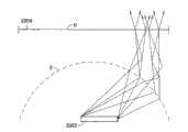
另一应用是作为视网膜成像相机。在视网膜成像中,靠近光轴的区域通常由成像光学元件阻隔,照明需要通过利用进一步远离光轴的区域进入视网膜。在这种情况下,可以以与物体侧的显微镜照明相似的方式使用成像通道。然而,不仅可利用反射镜反射成像光轴,还可以将配置设计为通过使用圆环形状的倾斜反射镜使得照明路径与成像光轴重合。 Another application is as a retinal imaging camera. In retinal imaging, regions close to the optical axis are usually blocked by imaging optics, and illumination needs to enter the retina by exploiting regions further away from the optical axis. In this case, the imaging channel can be used in a similar manner to microscope illumination on the object side. However, not only the imaging optical axis can be reflected by a mirror, but also the configuration can be designed so that the illumination path coincides with the imaging optical axis by using a donut-shaped inclined mirror. the
关于太阳能到电能的转换效率,太阳能碟式发电机是所有太阳能技术 中最有效的。这样的系统使用抛物面碟形反射镜的阵列来将太阳能聚焦到接收器上,接收器位于抛物面反射会聚器的焦点处。该接收器可包括光伏电池,以将太阳能直接捕获为电的形式。通常在高功率应用中,接收器包括工作流体,诸如油或者水,该流体被加热到几百摄氏度,并用于在发动机中产生电,发动机可以例如是蒸汽机或更优选为Stirling或Brayton循环发动机。碟型会聚器需要精确朝向太阳,因此需要在太阳在天空移动时追踪太阳。这样的太阳能碟型发电机具有若干缺点: Regarding the conversion efficiency of solar energy to electricity, solar dish generators are the most efficient of all solar technologies. Such systems use an array of parabolic dish mirrors to focus solar energy onto a receiver located at the focal point of a parabolic reflective concentrator. The receiver may include photovoltaic cells to capture solar energy directly into electricity. Typically in high power applications, the receiver comprises a working fluid, such as oil or water, which is heated to several hundred degrees Celsius and used to generate electricity in an engine, which may for example be a steam engine or more preferably a Stirling or Brayton cycle engine. The dish needs to be precisely oriented toward the sun, so it needs to track the sun as it moves across the sky. Such solar dish generators have several disadvantages:
太阳能碟型发电机的效率正比于抛物面会聚器的会聚比例。然而旋转抛物面的会聚效率并不处于最大的理论会聚效率,并且可以改进,这将会增加太阳能发电器的效率。 The efficiency of the solar dish generator is directly proportional to the convergence ratio of the parabolic concentrator. However the concentrating efficiency of the paraboloid of revolution is not at the maximum theoretical concentrating efficiency and can be improved, which will increase the efficiency of the solar generator. the
●通过使用现有抛物面会聚器在接收器处获得的辐射通量远远不到最大值,因为接收器处的光束的数值孔径受限。如果不是抛物面反射器就会具有很深的且很困难的机械布置。 • The radiant flux obtained at the receiver by using existing parabolic concentrators is far from the maximum, because the numerical aperture of the beam at the receiver is limited. If it were not for the parabolic reflectors it would have a deep and difficult mechanical arrangement. the
●现有技术系统中的接收器必须是上述反射器,这意味着很难接触。 • The receiver in the prior art system has to be the above mentioned reflector, which means that it is difficult to access. the
当系统追踪太阳的移动时,接收器需要与反射器一起移动。 The receiver needs to move with the reflector as the system tracks the movement of the sun. the
由于上述复杂的机械布置,成本很高。 Due to the complex mechanical arrangement described above, the cost is high. the
本发明的一项有利使用是提供用于这些太阳能碟型发电机的太阳能会聚器,其不具有上述这些缺点。这样的布置的优势包括: An advantageous use of the invention is to provide solar concentrators for these solar dish generators, which do not have the above-mentioned disadvantages. The advantages of such an arrangement include:
●会聚效率接近最大理论会聚效率; ●The convergence efficiency is close to the maximum theoretical convergence efficiency;
●接收器处光束的数值孔径可以超过以上的描述而显著增加,而不会增加会聚器的高度; The numerical aperture of the beam at the receiver can be significantly increased beyond that described above without increasing the height of the converging device;
●接收器可以位于反射器下面,允许容易地接触接收器进行维护; The receiver can be located under the reflector, allowing easy access to the receiver for maintenance;
●当会聚器追踪太阳的移动时,接收器可以是静止的; The receiver can be stationary while the concentrator tracks the movement of the sun;
●由于更简单的机械结构,总体上降低系统成本 ● Overall lower system cost due to simpler mechanical structure
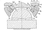
这样的装置可以如下制造。有待照明的物体可以例如是光伏电池,其将光能直接转换为电。热元件(其吸收光并将其转换为热)也可以是一些液体,诸如水或者油,可通过使用涡轮发电机产生电。这样的装置提供下面的优势。即使在液体具有比空气更高的折射率时,组元能够完全填充液 体内的物体的展度。组元在发热元件周围给出空间,由此不需要光学表面靠近强度最高的区域。例如,流体可以在半球拱顶之内,类似于拱顶围绕高效LED光源周围,如图8所示。可以使用其他转换系统,例如Stirling热机或蒸汽机。如果最大会聚比率对于接收器物体太高,可以将组元的设计改变为使得产生的斑点大于理论最小值,这缓解制造公差和太阳追踪精确度。这样的设备可用于基于太阳能的发热系统,烧水,太阳能烹饪,太阳能烤炉,以及太阳能发电系统(甚至最高可达兆瓦特范围)。 Such a device can be fabricated as follows. The object to be illuminated can be, for example, a photovoltaic cell, which converts light energy directly into electricity. The thermal element (which absorbs light and converts it to heat) can also be some liquid, such as water or oil, which can generate electricity by using a turbine generator. Such a device offers the following advantages. Even when the liquid has a higher refractive index than air, the constituents are able to completely fill the extent of the object within the liquid. The components give space around the heat-generating element, thereby not requiring optical surfaces close to the areas of highest intensity. For example, the fluid can be within a hemispherical dome, similar to a dome around a high-efficiency LED light source, as shown in FIG. 8 . Other conversion systems can be used, such as a Stirling heat engine or a steam engine. If the maximum convergence ratio is too high for the receiver object, the design of the elements can be changed such that the resulting spots are larger than the theoretical minimum, which eases manufacturing tolerances and sun tracking accuracy. Such devices can be used in solar-based heating systems, water heating, solar cooking, solar ovens, and solar power generation systems (even up to the megawatt range). the
如上所述的照明器的实施例通过使用Zemax光学设计软件进行测试。图16示出模型布局。LED 22被安装到反射镜52上,并与目标(强度(volume)检测器1602)相对沿光轴20设置。多个光线导向件(与图5A所示的类似)被设置在LED 22和目标1602之间,中继透镜92也被设置在通道结构和目标之间。光学通道结构的每一个绕光轴20圆柱对称。 Embodiments of luminaires as described above were tested using Zemax optical design software. Figure 16 shows the model layout.
图17A示出使用图16的照明器距离LED芯片22 11.5mm处的矩形照明。图17B示出具有更精确通道的同样照明器58的改进模型的矩形照明。尤其在图17B中,线性均匀照明的锐度相当显著。通过在中继透镜92和目标1602之间具有双锥形的透镜,照明的纵横比改变为4∶3,而不是方形。 FIG. 17A shows the illumination of a rectangle at a distance of 11.5 mm from the
根据本发明,成像通道A,B,C的实施例可以如下描述:成像通道将一个物体(例如光源)成像为图像(到小型显示屏上,到显微镜的样品上,等等)。整个设备(照明器/会聚器)的光轴20与通道的(以及形成这些通道的光线导向件的)旋转轴相同。径向横截平面是这样的平面,其包含所述旋转轴。径向方向是径向横截平面的x轴,垂直于轴20。切线方向垂直于径向横截平面。通道的每一径向横截平面包含2维光学系统(不同于“切线”方向中的通道光学系统)。该2维光学系统的光轴是径向横截平面中的通道的光轴。这像是整个系统中的子系统。这与整个组元的光轴不同。径向横截平面中通道的光轴并不与通道的辐射进入和出射光瞳之间的通道的旋转轴相交。通道的辐射进入光瞳是通道的2维光学系统(也就是,在径向横截平面中)的入射光瞳,其典型地近似在通道的第一表面处(但不一定是,见图6C-D)。通道的辐射出射光瞳是通道的2维光学系统(也 就是,在径向横截平面中)的出射光瞳,其典型地近似在通道的最后表面处(但不一定是,见图6C-D)。 Embodiments of the imaging channels A, B, C according to the invention can be described as follows: The imaging channels image an object (eg light source) as an image (onto a small display screen, onto a sample of a microscope, etc.). The
通道的径向横截平面具有三个功能部分(可以一体形成)。这三个功能被设计到通道中,并且从物体到图像按照下面的顺序: The radial cross-sectional plane of the channel has three functional parts (which can be integrally formed). These three functions are designed into the channel, and in the following order from object to image:
1.将物体成像到中间图像(在径向横截平面中)。 1. Imaging the object into an intermediate image (in the radial cross-section plane). the
2.将通道的辐射入射光瞳成像维通道的出射光瞳(在径向横截平面中)。 2. Image the radiation entrance pupil of the channel to the exit pupil of the dimension channel (in the radial cross-sectional plane). the
3.将中间图像成像为图像(在径向横截平面中)。 3. Imaging the intermediate image as an image (in the radial cross-sectional plane). the
所有这三个功能可以体现为环形光学光线导向件。通常,功能1和2由这样的光线导向件体现,其在径向横截平面中的2维横截面具有正的光焦度。功能3可以由具有正、负甚至零光焦度(典型地具有正光焦度)的光线导向件体现。每个功能可以体现为若干光学表面,折射、反射或衍射。表面也可以一体形成。通常,每个通道通过使用至少一个非球面表面(也就是,不具有圆弧横截面的光学表面)而达到最佳效果。 All three of these functions can be embodied as an annular optical light guide. Typically, functions 1 and 2 are performed by a light guide whose 2-dimensional cross-section in a radial cross-sectional plane has positive optical power. Function 3 can be performed by a light guide with positive, negative or even zero power (typically with positive power). Each function can be embodied as several optical surfaces, refractive, reflective or diffractive. The surface may also be integrally formed. Typically, each channel is best achieved by using at least one aspheric surface (ie, an optical surface that does not have a circular cross-section). the
根据本发明的内容,成像通道是圆柱对称的光线导向组元(可以包括一个或多个分立组元,也就是,光线导向件),其目的是从物体基本成像。当然,属于成像通道装置的真实部件可以在物理上包含非圆柱对称的其他部件。成像通道中执行成像功能的那些部分基本是圆柱对称的(例如,上述分段直线近似基本在该术语之内),而不执行成像功能的其他部件不必是圆柱对称的。 In the context of the present invention, an imaging channel is a cylindrically symmetric light-guiding component (which may comprise one or more discrete components, ie, light-guiding elements), the purpose of which is to substantially image an object. Of course, real components belonging to the imaging channel device may physically contain other components that are not cylindrically symmetric. Those parts of the imaging channel that perform an imaging function are substantially cylindrically symmetric (eg, the piecewise straight line approximation described above is substantially within that term), while other components that do not perform an imaging function need not be cylindrically symmetric. the
基本圆柱对称的成像通道具有居中的旋转轴。轴方向定义为平行于旋转轴的方向。径向方向是垂直于轴向方向的任意方向。轴向方向和任意径向方向限定一个径向横截平面。切线方向定义为垂直于径向横截平面。图18示出径向横截平面1802和与其相关的轴向1804,径向1806和切线1808方向矢量。成像通道的操作可以通过使用这样的坐标定义来描述。 A substantially cylindrically symmetric imaging channel has a centered axis of rotation. Axial directions are defined as directions parallel to the axis of rotation. A radial direction is any direction perpendicular to the axial direction. The axial direction and any radial direction define a radial cross-sectional plane. The tangential direction is defined as perpendicular to the radial cross-sectional plane. FIG. 18 shows a radial
在穿过成像通道的任意径向横截平面中,成像通道限定一个二维光线导向系统1810。也可以限定两个系统1810,1812,其相对于轴1814为镜像系统,如图18所示。当成像通道绕轴在大于180度之上圆柱对称时有可 能出现这种情况。在接下来的描述中,我们仅仅参照这些二维光线系统之一,也就是,例如图18的右手侧的系统1810。注意到,二维光线导向系统具有光轴1816,该光轴1816与成像通道的旋转轴1814并不相同,而是基本不同。因此二维光学系统的光轴对于每一单个径向横截平面都是不同的。 In any radial cross-sectional plane through the imaging channel, the imaging channel defines a two-dimensional
光线导向组元可以通过使用与光线光学元件中典型使用的术语基本相同的术语进行描述。子午光线是指从物体沿着径向横截平面发出的光线。典型的光学系统具有入射和出射光瞳。相似地,二维光线导向系统的每一个相对于物体1818的横截面在同一径向横截平面上具有入射光瞳和出射光瞳。入射光瞳可以是实或者虚的孔径,该孔径被限定为使得从物体的横截面朝向孔径的子午光线被导向通过二维光学系统。出射光瞳可以类似于光线光学元件那样限定。 Light directing components may be described using substantially the same terminology as is typically used in light optics. A meridional ray is a ray emanating from an object along a radial cross-sectional plane. A typical optical system has an entrance and exit pupil. Similarly, each cross-section of the two-dimensional light guide system relative to the object 1818 has an entrance pupil and an exit pupil on the same radial cross-sectional plane. The entrance pupil may be a real or imaginary aperture defined such that meridian rays from a cross-section of the object towards the aperture are directed through the two-dimensional optical system. The exit pupil can be defined similarly to the light optics. the
成像通道的一个特殊特征在于,来自物体的子午光线由径向横截平面的二维光线导向系统在同一径向横截平面上成像为中间图像,中间图像又进一步成像为图像。除此之外,成像通道的特征还在于,物体的中间图像并不交叉穿过成像通道的旋转轴,由此,各个径向横截平面的中间图像在旋转轴上不会彼此交叉。因此并由于各个径向横截平面仅在旋转轴上相交,各个径向横截平面的中间图像在任何地方都不会彼此交叉。 A special feature of the imaging channel is that the meridian rays from the object are imaged in the same radial cross-section plane by a two-dimensional light-guiding system in the radial cross-section plane, which is further imaged into an image. In addition, the imaging channel is characterized in that the intermediate images of the object do not intersect through the axis of rotation of the imaging channel, so that the intermediate images of the individual radial cross-section planes do not intersect each other on the axis of rotation. Therefore and since the individual radial cross-section planes only intersect on the axis of rotation, the intermediate images of the individual radial cross-section planes do not intersect each other anywhere. the
这不同于现有的校准、光束成形以及成像设备(例如TIR-准直仪或高NA物镜)的内容。那些设备或者不会如上所述地形成中间图像进而进行成像,或者如果它们形成中间图像,各个径向横截平面的中间图像在一些位置互相交叉。这可能出现在例如当各个径向横截平面的二维光线导向系统的光轴与设备的旋转轴重合的情况下。 This differs from existing collimation, beam shaping and imaging devices such as TIR-collimators or high NA objectives. Those devices either do not form intermediate images as described above for imaging, or if they form intermediate images, the intermediate images of the respective radial cross-section planes intersect each other at some positions. This may occur, for example, when the optical axis of the two-dimensional light guide system of the respective radial cross-sectional plane coincides with the rotational axis of the device. the
成像通道这些特殊性质连同描述的其他特殊性质产生本发明的极大优势,这些优势在本说明中会变得明显。 These particular properties of the imaging channel, along with others described, give rise to great advantages of the present invention which will become apparent in this specification. the
根据上述的成像配置,成像通道在每一单个径向横截平面中形成物体的像。但是没有沿任意径向横截平面传播的光线,也就是被称为斜光线的光线会怎样呢?例如在A.S.Glassner,Morgan Kaufmann Publisher,9th edition,2002,“An Introduction To Ray Tracing”一书的第三章中提出了对斜光线通过圆柱对称光线导向系统的精确追踪。当在通常(r,z)坐标系统中表示斜光线的路径时(也就是,由r表示的水平轴是离旋转轴的距离,竖直轴为z坐标),光线路径沿着二次曲线部分,而不是典型直线部分前进。本发明的一项很重要的发现在于,当成像通道被布置为使得物体点离径向横截平面的二维光线导向系统的入射光瞳中心的距离显著大于物体点离同一径向横截平面的距离时,在计算通过成像通道的斜光线的径向分量时斜光线可以基本按照子午光线处理。其结果是,如果我们沿着径向横截平面的切线方向投影进入到各个径向横截平面的入射光瞳的斜光线,由此获得子午光线,我们可以对获得的子午光线通过二维光线导向系统进行追踪,并由此获得该子午光线在出射光瞳处的径向分量。该子午光线在出射光瞳处的径向分量的大小现在基本与斜光线在其出射光瞳处的径向分量的大小相同。该近似的真实度的精确性取决于上述大小的比值。例如当物体离入射光瞳的距离近似为物体最大宽度三倍时,对于照明质量图像获得足够好的近似。因此,任意单个出射光瞳上的包括子午光线和斜光线的任何光线的径向分量都可通过成像通道的径向形状而知晓并限定。 According to the imaging arrangement described above, the imaging channels form an image of the object in each single radial cross-sectional plane. But what about rays that do not travel along any radial cross-sectional plane, known as oblique rays? For example, in the third chapter of AS Glassner, Morgan Kaufmann Publisher,9th edition, 2002, "An Introduction To Ray Tracing", the precise tracing of oblique rays through a cylindrically symmetrical ray guiding system is proposed. When representing the path of an oblique ray in the usual (r,z) coordinate system (that is, the horizontal axis denoted by r is the distance from the axis of rotation and the vertical axis is the z coordinate), the ray path follows the quadratic portion , rather than the typical straight section forward. A very important discovery of the present invention is that when the imaging channel is arranged such that the distance of the object point from the center of the entrance pupil of the two-dimensional light guide system of the radial cross-sectional plane is significantly greater than that of the object point from the same radial cross-sectional plane When calculating the radial component of oblique rays passing through the imaging channel, the oblique rays can basically be treated as meridional rays. As a result, if we obtain meridional rays by projecting oblique rays entering the entrance pupils of the respective radial cross-sectional planes along the tangent direction of the radial cross-sectional planes, we can obtain meridional rays through the two-dimensional ray The guiding system tracks and thus obtains the radial component of the meridian ray at the exit pupil. The radial component of the meridional ray at the exit pupil is now substantially the same size as the radial component of the oblique ray at its exit pupil. The accuracy of this approximation depends on the ratio of the above magnitudes. A good enough approximation is obtained for an illumination quality image, eg when the distance of the object from the entrance pupil is approximately three times the maximum width of the object. Thus, the radial component of any ray on any single exit pupil, including meridional and oblique rays, is known and defined by the radial shape of the imaging channel.
从这样的布置,在该布置的每一单个二维光线导向系统中成像通道形成物体的中间图像,然后进一步将该中间图像成像为图像,其进一步结果是,成像通道基本在每一单个径向横截平面中将入射光瞳成像到出射光瞳。成像通道的(全)入射光瞳包含属于某些二维光线导向系统的某些入射光瞳的所有点。相似地,成像通道的(全)出射光瞳包含属于某些二维光线导向系统的某些出射光瞳的所有点。现在,(全)入射光瞳上的所有点基本被映射到(全)出射光瞳上的特定点。换言之,入射光瞳被基本成像到出射光瞳。 From such an arrangement, in each single two-dimensional light guide system of the arrangement, the imaging channel forms an intermediate image of the object, and then further images the intermediate image into an image, and as a further result, the imaging channel substantially in each single radial direction The entrance pupil is imaged to the exit pupil in the cross-sectional plane. The (full) entrance pupil of an imaging channel contains all points belonging to certain entrance pupils of certain two-dimensional ray guiding systems. Similarly, the (full) exit pupil of an imaging channel contains all points belonging to certain exit pupils of certain two-dimensional ray guiding systems. Now basically all points on the (full) entrance pupil are mapped to a specific point on the (full) exit pupil. In other words, the entrance pupil is substantially imaged to the exit pupil. the
为了完成斜光线的成像功能,还需要在成像通道的切线方向完成成像。这通过利用旋转对称的光线导向系统的偏斜不变性质以创新的方式实现(例如参见Roland Winston,Elsevier Academic Press 2005,“NonimagingOptics”一书的第十章)。 In order to complete the imaging function of oblique rays, it is also necessary to complete imaging in the tangential direction of the imaging channel. This is achieved in an innovative way by exploiting the skew-invariant property of rotationally symmetric ray-guiding systems (see eg Roland Winston, Elsevier Academic Press 2005, Chapter 10 of the book "Nonimaging Optics"). the
光线的偏斜不变量(或偏斜度)定义为: The skew invariant (or skewness) of a ray is defined as:
其中 是沿旋转对称轴取向的单位矢量, 

让我们观察成像通道的出射光瞳处的任意光线。令轴向、径向和切向方向的光线分量分别为 


其中,r是在出射光瞳处光线离旋转轴的距离, 是在出射光瞳处光线的切向分量的尺寸。由于
其中,k′t和r′关联于成像通道的入射光瞳处的光线。因此,通过调整从入射光瞳到出射光瞳的映射,可以调整斜光线的切线分量。具体地,通过该方式,切线成像可以匹配到径向成像,因此成像通道对斜光线也完成成像功能。 wherek't and r' relate to rays at the entrance pupil of the imaging channel. Thus, by adjusting the mapping from the entrance pupil to the exit pupil, the tangent component of oblique rays can be adjusted. Specifically, in this way, tangential imaging can be matched to radial imaging, so the imaging channel can also perform imaging functions for oblique rays.
本发明实施例的特殊特征在于,入射光瞳以这样的方式映射到出射光瞳,即,入射光瞳处和出射光瞳处的对应点具有离旋转轴基本相等的距离。通过利用这样的成像通道实施例,有可能对从物体发射到绕物体整个半球 (或者更多)的光线进行成像。 A particular feature of an embodiment of the invention is that the entrance pupil is mapped to the exit pupil in such a way that corresponding points at the entrance pupil and at the exit pupil have substantially equal distances from the axis of rotation. By utilizing such an imaging channel embodiment, it is possible to image rays emitted from an object to a full hemisphere (or more) around the object. the
本发明的内容描述了一种成像通道组元,其能够将物体成像为图像。成像通道可设计为在径向和切线方向具有不同的成像特性。可以在径向和切线方向单独调整成像度。成像通道能够从形成离旋转轴0到135度角度的方向对物体成像。这是因为,相比于常规成像内容,成像通道允许对光线导向组元布置的更大自由度。成像通道由圆柱对称光线导向组元制成,这从可制造性的角度来说被认为是有利的。 SUMMARY OF THE INVENTION An imaging channel component is described which is capable of imaging an object as an image. Imaging channels can be designed to have different imaging properties in radial and tangential directions. The degree of imaging can be adjusted independently in radial and tangential directions. The imaging channel is capable of imaging objects from directions forming angles from 0 to 135 degrees from the axis of rotation. This is because imaging channels allow greater freedom in the placement of light-guiding components than conventional imaging content. The imaging channel is made of cylindrically symmetric light-guiding components, which is considered to be advantageous from a manufacturability point of view. the
值得注意的,成像通道的实施需要在最少三个分立位置对光线进行导向,当然如果一个组元延伸至这三个分立位置,也可以通过一个组元实施。令这至少三个光线导向装置被称为第一,第二和第三光线导向组元。 It is worth noting that the implementation of the imaging channel needs to guide the light at least three discrete positions. Of course, if a component extends to these three discrete positions, it can also be implemented by a component. Let the at least three light guiding means be referred to as first, second and third light guiding elements. the
还值得注意的是,本发明的内容在如下情况下也是有效的,也就是如果成像通道不是在径向横截平面中形成一个中间图像,而是形成两个或更多个连续中间图像,这些中间图像彼此共轭,并且与物体和图像共轭。这允许光束路径如何布置的更大的自由度。通过这种方式,有可能提供每个通道仍具有高NA的相对较长的成像通道。 It is also worth noting that the teachings of the present invention are also valid if, instead of forming one intermediate image in the radial cross-sectional plane, the imaging channels form two or more consecutive intermediate images, these The intermediate images are conjugates to each other, and to the object and the image. This allows greater freedom in how the beam paths are arranged. In this way, it is possible to provide relatively long imaging channels that still have high NA per channel. the
仍然根据本发明的内容,本发明的成像通道的一个实施例为一种装置,包括至少三个光线导向组元,这些组元基本绕轴圆柱对称。这样的光线导向组元可以是任何基本圆柱对称的结构,该结构通过改变至少某些光线的方向对光线进行导向。这样的光线导向组元仅仅改变光线的方向矢量的这些分量,所述分量垂直于或平行于组元的旋转轴(也就是,在组元的径向横截平面上的分量),而基本不改变光线方向矢量的其余分量(也就是,相对于组元的旋转轴的切线方向矢量)。 Still in accordance with the teachings of the present invention, an embodiment of the imaging channel of the present invention is a device comprising at least three light-guiding elements substantially cylindrically symmetrical about an axis. Such a light directing component may be any substantially cylindrically symmetric structure that guides light by redirecting at least some of the light. Such a ray directing component changes only those components of the ray's direction vector that are perpendicular or parallel to the component's axis of rotation (that is, the component in the component's radial cross-sectional plane), without substantially Changes the remaining components of the ray's direction vector (that is, the tangent direction vector relative to the component's rotation axis). the
在成像通道的一个实施例中,入射光瞳被限定为物理上可能的入射光瞳的一部分。物体可以被限定为任意光线光源,或其一部分,或其图像或虚像,如上所述。 In one embodiment of the imaging channel, the entrance pupil is defined as a fraction of the physically possible entrance pupil. An object may be defined as any source of light, or a portion thereof, or an image or virtual image thereof, as described above. the
描述如上所述的照明器组元的另外方式如下:图20示出Lambertian光源2002连同其上面的照明光瞳2004。光源将光发射到很大的张角,例如,发射到整个半球。照明光瞳处的每一点具有光的角度分布,其向无穷 远产生光源的图像。图像也可以成到非无穷远的某些其他距离,不过这里远心输出仅选择作为一个示例性情况。照明光瞳的宽度和角度张角通过展度定律关联。这是高NA成像的目标,也是理想照明系统的目标。 A further way of describing the illuminator components as described above is as follows: Figure 20 shows a
图20进一步示出从光源发出的光线(2006,2008,2010,2012,2014,1016)和在照明光瞳处的对应光线(2018,2020,2022,2024,2026,2028)。现在的问题是怎样设计并构建这样的光学系统,使得所有光线在3维中同时被导向到照明光瞳处的对应光线(示例性光线路径如虚线示出),而该图仅仅示出了2维的情况。诸如高NA透镜系统的许多常规解决方案试图通过用同样的透镜组元处理所有光线来解决这一问题。这导致对可以使用的几何形状的若干限制,因此常规系统还不能完善地实施上述系统而没有严重缺点,尤其在光源处于折射率高于1的材料之内时。容易理解,通常很容易使得中心区域很好地起作用,但是如果我们想要使得中心区域起作用并且同时还使得侧发射的光被适当处理,那就要困难很多。 Fig. 20 further shows rays (2006, 2008, 2010, 2012, 2014, 1016) emanating from the light source and corresponding rays (2018, 2020, 2022, 2024, 2026, 2028) at the illumination pupil. The question now is how to design and construct such an optical system so that all rays are simultaneously directed in 3 dimensions to the corresponding rays at the illumination pupil (example ray paths are shown as dashed lines), while the figure only shows 2 dimensional situation. Many conventional solutions, such as high NA lens systems, try to solve this problem by processing all rays with the same lens elements. This leads to several limitations on the geometries that can be used, so conventional systems have not been able to perfectly implement the above without serious drawbacks, especially when the light source is within a material with a refractive index higher than one. It's easy to understand that it's usually easy to get the center area to work well, but it's a lot more difficult if we want to get the center area to work and also have the side-emitted light being handled properly. the
上述呈现的成像通道为这个问题提供了现实的解决方案。不需要用同一光学表面导向所有的光线。连续的光线流可以在某些表面被分为若干圆柱对称的“通道”。(近似为如上所述的半球,取决于设计的优化,也可以不同于半球)。现在可以单独设计每一通道,使得光线被传递到需要的位置和方向,并且现在光学系统对于光源之上的不同竖直角(θ)可以是不同的。这为设计提供了更大的自由度,并允许使用上述的本发明的通道,所述通道进行期望的变换。然后,来自通道的光束在表面U组合为一个立体光束。为了维持光束的展度,每一通道径向横截平面的2维光学系统的入射光瞳和出射光瞳需要形成连续表面。除此之外,需要调整从通道的输出光束的方向,使得角度分布在照明器的整个输出平面上都很平滑。图21示出通道实施的示意性示例光线路径。 The imaging channels presented above provide a realistic solution to this problem. It is not necessary to direct all rays with the same optical surface. A continuous stream of light rays can be divided into several cylindrically symmetrical "channels" on certain surfaces. (Approximately hemisphere as above, depending on design optimization, can also be different than hemisphere). Each channel can now be designed individually so that the light is delivered to the desired position and direction, and now the optical system can be different for different vertical angles (θ) above the light source. This provides greater freedom in design and allows the use of the inventive channels described above, which perform the desired transformations. The beams from the channels are then combined at surface U into a solid beam. In order to maintain the beam etendue, the entrance pupil and exit pupil of the 2D optical system in the radial cross-sectional plane of each channel need to form continuous surfaces. In addition to this, the direction of the output beam from the channel needs to be adjusted so that the angular distribution is smooth across the entire output plane of the illuminator. Figure 21 shows a schematic example ray path for a channel implementation. the
尽管示出并描述了示例性光学通道及其组合,本发明并不仅限于这里详述的实施例。 While exemplary optical channels and combinations thereof are shown and described, the invention is not limited to the embodiments detailed herein. the
Claims (63)
Applications Claiming Priority (3)
| Application Number | Priority Date | Filing Date | Title |
|---|---|---|---|
| US83707106P | 2006-08-10 | 2006-08-10 | |
| US60/837,071 | 2006-08-10 | ||
| PCT/EP2007/058313WO2008017718A1 (en) | 2006-08-10 | 2007-08-10 | Illuminator method and device |
Publications (2)
| Publication Number | Publication Date |
|---|---|
| CN101523267A CN101523267A (en) | 2009-09-02 |
| CN101523267Btrue CN101523267B (en) | 2012-06-20 |
Family
ID=38626227
Family Applications (1)
| Application Number | Title | Priority Date | Filing Date |
|---|---|---|---|
| CN2007800377684AExpired - Fee RelatedCN101523267B (en) | 2006-08-10 | 2007-08-10 | Illuminator method and device |
Country Status (11)
| Country | Link |
|---|---|
| US (2) | US7729578B2 (en) |
| EP (1) | EP2052287A1 (en) |
| JP (2) | JP4647029B2 (en) |
| KR (1) | KR20090057242A (en) |
| CN (1) | CN101523267B (en) |
| AU (1) | AU2007283578A1 (en) |
| BR (1) | BRPI0716036A2 (en) |
| CA (1) | CA2660423A1 (en) |
| RU (1) | RU2009108005A (en) |
| TW (1) | TW200821623A (en) |
| WO (1) | WO2008017718A1 (en) |
Cited By (1)
| Publication number | Priority date | Publication date | Assignee | Title |
|---|---|---|---|---|
| TWI633331B (en)* | 2016-05-09 | 2018-08-21 | 大立光電股份有限公司 | Imaging lens assembly and electronic device |
Families Citing this family (48)
| Publication number | Priority date | Publication date | Assignee | Title |
|---|---|---|---|---|
| BRPI0716036A2 (en)* | 2006-08-10 | 2013-09-24 | Upstream Engineering Oy | Method and illuminating device |
| CN101539266B (en)* | 2008-03-19 | 2011-05-11 | 富准精密工业(深圳)有限公司 | Luminous element and lens thereof |
| US20090251751A1 (en)* | 2008-04-02 | 2009-10-08 | Kurt Kuhlmann | Optical Imaging System |
| US8764198B2 (en)* | 2008-04-29 | 2014-07-01 | Himax Display, Inc. | Projection system having rotationally asymmetrical illumination unit for emitting light along optic axis |
| JP2009288611A (en)* | 2008-05-30 | 2009-12-10 | Chinontec Kk | Projection type display device |
| NL2002295C2 (en)* | 2008-12-05 | 2009-12-14 | Michel Robert Ten Wolde | Escape route illumination device for e.g. hotel, has lighting device mounted to wall at specific mounting height from floor, where lighting device illuminates predetermined area of floor |
| KR20100073806A (en)* | 2008-12-23 | 2010-07-01 | 삼성전자주식회사 | Collimate lens assembly |
| US20100284201A1 (en)* | 2009-05-06 | 2010-11-11 | Upstream Engineering Oy | Illuminator using non-uniform light sources |
| US8033691B2 (en)* | 2009-05-12 | 2011-10-11 | Koninklijke Philips Electronics N.V. | LED lamp producing sparkle |
| US8466400B2 (en) | 2009-07-24 | 2013-06-18 | Cewa Technologies, Inc. | Calibration system for solar collector installation |
| JP5187342B2 (en)* | 2010-04-23 | 2013-04-24 | ウシオ電機株式会社 | LED light emitting device |
| US8926156B2 (en)* | 2010-08-03 | 2015-01-06 | Enplas Corporation | Light-emitting device and illumination device |
| EP2461082B1 (en)* | 2010-12-02 | 2017-06-28 | Aether Systems Inc. | Omnidirectional LED lamp |
| WO2012114522A1 (en) | 2011-02-25 | 2012-08-30 | 日立コンシューマエレクトロニクス株式会社 | Projection image display device |
| US8742655B2 (en)* | 2011-07-22 | 2014-06-03 | Guardian Industries Corp. | LED lighting systems with phosphor subassemblies, and/or methods of making the same |
| TWI437266B (en)* | 2011-07-28 | 2014-05-11 | Univ Nat Taiwan Science Tech | Light harvesting lens module |
| DE102011082770B4 (en)* | 2011-09-15 | 2018-11-08 | Leica Microsystems (Schweiz) Ag | Microscope with transmitted-light illumination for critical illumination |
| KR101248999B1 (en)* | 2011-11-30 | 2013-04-01 | 에스엘 주식회사 | Vehicle lamp |
| JP6198748B2 (en)* | 2011-12-13 | 2017-09-20 | フィリップス ライティング ホールディング ビー ヴィ | Optical collimator for LED light |
| CN103988110B (en)* | 2011-12-13 | 2018-09-28 | 飞利浦照明控股有限公司 | Optics collimator for LED light |
| TWI456266B (en)* | 2012-02-22 | 2014-10-11 | 嵐雅光學股份有限公司 | Non-imaging optical lens and lighting device with the lens |
| KR101417258B1 (en) | 2012-04-05 | 2014-07-08 | 엘지이노텍 주식회사 | Member for controlling luminous flux and display device having the same |
| US9890926B2 (en)* | 2012-08-02 | 2018-02-13 | Fraen Corporation | Low profile multi-lens TIR |
| JP2014089941A (en)* | 2012-10-03 | 2014-05-15 | Koito Mfg Co Ltd | Vehicular lighting unit |
| CN104641169B (en)* | 2012-11-20 | 2018-01-26 | 西门子公司 | indicator light |
| EP2965141A1 (en)* | 2013-03-07 | 2016-01-13 | Koninklijke Philips N.V. | Low-profile optical arrangement |
| US9732941B2 (en) | 2013-03-11 | 2017-08-15 | Lighthouse Tech Pte. Ltd. | Diffuse light source and visual dazzler system made therefrom |
| DE102013204945B4 (en)* | 2013-03-20 | 2015-03-26 | Leica Microsystems (Schweiz) Ag | Microscope with transmitted-light illumination for critical illumination |
| CN105318207B (en)* | 2014-06-30 | 2019-01-15 | 欧普照明股份有限公司 | A kind of lamps and lanterns |
| IN2015CH02472A (en)* | 2015-05-15 | 2015-05-22 | Noble Nevin | |
| WO2017075378A1 (en) | 2015-10-28 | 2017-05-04 | Acera LLC | Elliptical optical lens for high output led |
| CN106813208A (en)* | 2015-12-02 | 2017-06-09 | 欧普照明股份有限公司 | A kind of lens and a kind of LED |
| FR3045781B1 (en)* | 2015-12-18 | 2020-03-06 | Valeo Vision Belgique | LUMINOUS MODULE, PARTICULARLY FOR HIGH LIGHTS WITH SMOOTH APPEARANCE |
| US10808965B2 (en) | 2016-06-24 | 2020-10-20 | Alliance For Sustainable Energy, Llc | Secondary reflectors for solar collectors and methods of making the same |
| JP6827301B2 (en)* | 2016-11-16 | 2021-02-10 | 三菱電機株式会社 | Optical lens, light source device and lighting device |
| EP3339722B1 (en)* | 2016-12-20 | 2019-08-14 | Obelux Oy | Obstruction illuminator, obstruction illuminator assembly and installation method |
| TWI651546B (en)* | 2017-02-13 | 2019-02-21 | 立碁電子工業股份有限公司 | Thinned zoom optical system |
| US10816939B1 (en) | 2018-05-07 | 2020-10-27 | Zane Coleman | Method of illuminating an environment using an angularly varying light emitting device and an imager |
| US11184967B2 (en) | 2018-05-07 | 2021-11-23 | Zane Coleman | Angularly varying light emitting device with an imager |
| CN110388624B (en)* | 2018-06-24 | 2021-07-27 | 广州市意顿光学设计有限公司 | Collimating lens for preventing glare |
| KR102616540B1 (en)* | 2018-10-15 | 2023-12-21 | 현대모비스 주식회사 | Optical device |
| US12023005B2 (en) | 2019-01-02 | 2024-07-02 | Fraen Corporation | Positioning a tube in a lumen via transillumination |
| JP7300879B2 (en)* | 2019-04-24 | 2023-06-30 | 三菱電機株式会社 | Optical lens, light source device and illumination device |
| JP7148813B2 (en) | 2019-10-30 | 2022-10-06 | 日亜化学工業株式会社 | Light source device |
| JP7231831B2 (en) | 2019-10-30 | 2023-03-02 | 日亜化学工業株式会社 | Light source device |
| US11782205B2 (en) | 2021-04-28 | 2023-10-10 | Nichia Corporation | Light-emitting device including movement mechanism |
| US20240176051A1 (en)* | 2022-11-30 | 2024-05-30 | Panasonic Automotive Systems Company Of America, Division Of Panasonic Corporation Of North America | Diffuser to improve uniformity of head-up display image brightness |
| TWI848817B (en)* | 2023-09-13 | 2024-07-11 | 逢甲大學 | High efficiency projection lens assembly with highly uniform rectangular focused halo and size adjustment method of the rectangular focused halo thereof |
Citations (5)
| Publication number | Priority date | Publication date | Assignee | Title |
|---|---|---|---|---|
| US2224178A (en)* | 1940-05-08 | 1940-12-10 | Ralph E Bitner | Catadioptrical lens system |
| US2254962A (en)* | 1937-09-22 | 1941-09-02 | George M Cressaty | Unitary lens system |
| CN1402884A (en)* | 1999-11-30 | 2003-03-12 | 欧姆龙株式会社 | Optical device and machine using same |
| US20050174779A1 (en)* | 2002-05-17 | 2005-08-11 | Kenji Yoneda | Light emitting diode and method for fabricating the same |
| CN1727919A (en)* | 2004-07-13 | 2006-02-01 | 联邦信号瓦马股份有限公司 | Internally-reflecting collimation lens |
Family Cites Families (44)
| Publication number | Priority date | Publication date | Assignee | Title |
|---|---|---|---|---|
| GB456520A (en)* | 1935-04-09 | 1936-11-09 | Arthur George Cooke | Improvements in or relating to lamps, searchlights, projectors and the like |
| GB1211027A (en) | 1966-11-14 | 1970-11-04 | Minnesota Mining & Mfg | Reflector structures and die for forming reflector structures |
| US3834789A (en)* | 1973-02-02 | 1974-09-10 | Dominion Auto Access | Reflecting device |
| DE2542075A1 (en)* | 1975-09-20 | 1977-07-21 | Leitz Ernst Gmbh | LIGHTING DEVICE FOR LIGHT AND DARK FIELD ILLUMINATION |
| US5008496A (en)* | 1988-09-15 | 1991-04-16 | Siemens Aktiengesellschaft | Three-dimensional printed circuit board |
| KR930003307B1 (en)* | 1989-12-14 | 1993-04-24 | 주식회사 금성사 | Stereoscopic projector |
| US5264063A (en) | 1990-05-16 | 1993-11-23 | Reflexite Corporation | Method for making flexible retroreflective sheet material |
| DE69228096T2 (en)* | 1991-03-20 | 1999-07-01 | Mitsubishi Denki K.K., Tokio/Tokyo | PROJECTION TYPE DISPLAY DEVICE |
| SE9300958L (en) | 1993-03-23 | 1994-09-24 | Nova Onab Optica Ab | Offset projector |
| US6417967B1 (en)* | 1994-10-27 | 2002-07-09 | Massachusetts Institute Of Technology | System and method for efficient illumination in color projection displays |
| US5728324A (en)* | 1995-01-31 | 1998-03-17 | Digital Optics Corporation | Molding diffractive optical elements |
| WO1997001128A1 (en) | 1995-06-22 | 1997-01-09 | Optica Nova Onab Ab | Illumination arrangement for projection with reflective displays |
| JP3409587B2 (en) | 1996-05-14 | 2003-05-26 | オムロン株式会社 | Optical path conversion optical element, image display device, and light projector |
| JPH10186112A (en) | 1996-12-19 | 1998-07-14 | Sekinosu Kk | Prism assembly and its production |
| US6407868B1 (en)* | 1997-05-13 | 2002-06-18 | Nikon Corporation | Cross dichroic prism, method of making the same, and full-color projector using the same |
| JP3635867B2 (en)* | 1997-06-03 | 2005-04-06 | 株式会社日立製作所 | Projection type liquid crystal display device |
| US5971545A (en)* | 1997-06-25 | 1999-10-26 | Hewlett-Packard Company | Light source for projection display |
| JP3585097B2 (en)* | 1998-06-04 | 2004-11-04 | セイコーエプソン株式会社 | Light source device, optical device and liquid crystal display device |
| US6429583B1 (en)* | 1998-11-30 | 2002-08-06 | General Electric Company | Light emitting device with ba2mgsi2o7:eu2+, ba2sio4:eu2+, or (srxcay ba1-x-y)(a1zga1-z)2sr:eu2+phosphors |
| US6155699A (en)* | 1999-03-15 | 2000-12-05 | Agilent Technologies, Inc. | Efficient phosphor-conversion led structure |
| JP3633376B2 (en)* | 1999-06-21 | 2005-03-30 | セイコーエプソン株式会社 | Method for manufacturing polarization separation device |
| US6686691B1 (en)* | 1999-09-27 | 2004-02-03 | Lumileds Lighting, U.S., Llc | Tri-color, white light LED lamps |
| ES2157846B1 (en)* | 1999-12-02 | 2002-03-01 | Univ Madrid Politecnica | DEVICE WITH DISCONTINUOUS LENS WITH INTERNAL TOTAL REFLECTION AND ASPHERIC DIOPTRIC FOR CONCENTRATION OR COLIMATION OF RADIANT ENERGY. |
| US6733139B2 (en)* | 2000-06-05 | 2004-05-11 | Hewlett-Packard Development Company, L.P. | Projector with narrow-spectrum light source to complement broad-spectrum light source |
| DE10033502A1 (en)* | 2000-07-10 | 2002-01-31 | Osram Opto Semiconductors Gmbh | Optoelectronic module, process for its production and its use |
| US6686676B2 (en)* | 2001-04-30 | 2004-02-03 | General Electric Company | UV reflectors and UV-based light sources having reduced UV radiation leakage incorporating the same |
| TW522281B (en) | 2001-05-21 | 2003-03-01 | Hitachi Ltd | Projector |
| JP4076056B2 (en)* | 2001-05-21 | 2008-04-16 | 富士フイルム株式会社 | Magnetic transfer method |
| CN1298175C (en) | 2001-07-06 | 2007-01-31 | 以克斯普雷有限公司 | Image projecting device and method |
| KR100440958B1 (en)* | 2001-10-12 | 2004-07-21 | 삼성전자주식회사 | Illumination system and a projector imploying it |
| TW571119B (en)* | 2001-12-20 | 2004-01-11 | Delta Electronics Inc | Image projection device with integrated semiconductor light emitting element light source |
| JP3931127B2 (en)* | 2002-09-03 | 2007-06-13 | オリンパス株式会社 | LIGHTING DEVICE AND DISPLAY DEVICE USING THE SAME |
| JP4397394B2 (en)* | 2003-01-24 | 2010-01-13 | ディジタル・オプティクス・インターナショナル・コーポレイション | High density lighting system |
| FI20030583A7 (en)* | 2003-04-16 | 2004-10-17 | Upstream Eng Oy | Data projector |
| KR20070092330A (en)* | 2003-04-16 | 2007-09-12 | 업스트림 엔지니어링 오와이 | 2d / 3d data projector |
| JP2004335992A (en)* | 2003-04-18 | 2004-11-25 | Victor Co Of Japan Ltd | Light source unit and projection display device applied with the light source unit |
| US20040219464A1 (en)* | 2003-05-01 | 2004-11-04 | Dunham Gregory David | Diffractive optical elements formed on plastic surface and method of making |
| JP2005003900A (en)* | 2003-06-11 | 2005-01-06 | Seiko Epson Corp | projector |
| FI118991B (en)* | 2004-02-09 | 2008-06-13 | Upstream Engineering Oy | A method for manufacturing three-dimensional optical components |
| JP2005283918A (en)* | 2004-03-29 | 2005-10-13 | Fujinon Corp | Light source device for illumination |
| US20060139575A1 (en)* | 2004-12-23 | 2006-06-29 | Upstream Engineering Oy | Optical collection and distribution system and method |
| ITMI20050018A1 (en)* | 2005-01-07 | 2006-07-08 | Fraen Corp Srl | LUMINOUS LIGHT VARIABLE LIGHTING DISPOSITORY IN PARTICULAR FOR AN ELECTRIC TORCH |
| BRPI0716036A2 (en)* | 2006-08-10 | 2013-09-24 | Upstream Engineering Oy | Method and illuminating device |
| JP2009288611A (en)* | 2008-05-30 | 2009-12-10 | Chinontec Kk | Projection type display device |
- 2007
- 2007-08-10BRBRPI0716036-4A2Apatent/BRPI0716036A2/ennot_activeApplication Discontinuation
- 2007-08-10EPEP07802568Apatent/EP2052287A1/ennot_activeWithdrawn
- 2007-08-10AUAU2007283578Apatent/AU2007283578A1/ennot_activeAbandoned
- 2007-08-10CACA002660423Apatent/CA2660423A1/ennot_activeAbandoned
- 2007-08-10TWTW096129500Apatent/TW200821623A/enunknown
- 2007-08-10USUS11/891,362patent/US7729578B2/ennot_activeExpired - Fee Related
- 2007-08-10WOPCT/EP2007/058313patent/WO2008017718A1/enactiveApplication Filing
- 2007-08-10JPJP2009523301Apatent/JP4647029B2/ennot_activeExpired - Fee Related
- 2007-08-10CNCN2007800377684Apatent/CN101523267B/ennot_activeExpired - Fee Related
- 2007-08-10KRKR1020097004918Apatent/KR20090057242A/ennot_activeCeased
- 2007-08-10RURU2009108005/28Apatent/RU2009108005A/enunknown
- 2010
- 2010-05-17USUS12/800,551patent/US8139909B2/ennot_activeExpired - Fee Related
- 2010-12-07JPJP2010272270Apatent/JP2011096666A/ennot_activeCeased
Patent Citations (5)
| Publication number | Priority date | Publication date | Assignee | Title |
|---|---|---|---|---|
| US2254962A (en)* | 1937-09-22 | 1941-09-02 | George M Cressaty | Unitary lens system |
| US2224178A (en)* | 1940-05-08 | 1940-12-10 | Ralph E Bitner | Catadioptrical lens system |
| CN1402884A (en)* | 1999-11-30 | 2003-03-12 | 欧姆龙株式会社 | Optical device and machine using same |
| US20050174779A1 (en)* | 2002-05-17 | 2005-08-11 | Kenji Yoneda | Light emitting diode and method for fabricating the same |
| CN1727919A (en)* | 2004-07-13 | 2006-02-01 | 联邦信号瓦马股份有限公司 | Internally-reflecting collimation lens |
Cited By (1)
| Publication number | Priority date | Publication date | Assignee | Title |
|---|---|---|---|---|
| TWI633331B (en)* | 2016-05-09 | 2018-08-21 | 大立光電股份有限公司 | Imaging lens assembly and electronic device |
Also Published As
| Publication number | Publication date |
|---|---|
| CA2660423A1 (en) | 2008-02-14 |
| CN101523267A (en) | 2009-09-02 |
| US8139909B2 (en) | 2012-03-20 |
| US20100232176A1 (en) | 2010-09-16 |
| JP4647029B2 (en) | 2011-03-09 |
| AU2007283578A1 (en) | 2008-02-14 |
| WO2008017718A1 (en) | 2008-02-14 |
| TW200821623A (en) | 2008-05-16 |
| US20080037116A1 (en) | 2008-02-14 |
| KR20090057242A (en) | 2009-06-04 |
| RU2009108005A (en) | 2010-09-20 |
| EP2052287A1 (en) | 2009-04-29 |
| JP2010500708A (en) | 2010-01-07 |
| BRPI0716036A2 (en) | 2013-09-24 |
| JP2011096666A (en) | 2011-05-12 |
| US7729578B2 (en) | 2010-06-01 |
Similar Documents
| Publication | Publication Date | Title |
|---|---|---|
| CN101523267B (en) | Illuminator method and device | |
| US6639733B2 (en) | High efficiency non-imaging optics | |
| US7181378B2 (en) | Compact folded-optics illumination lens | |
| TWI294023B (en) | Reflective illumination device | |
| EP1753996B1 (en) | An apparatus and method for improved illumination area fill | |
| US9256007B2 (en) | Light collection and illumination systems employing planar waveguide | |
| US20090071467A1 (en) | Multi-junction solar cells with a homogenizer system and coupled non-imaging light concentrator | |
| WO2015038134A1 (en) | Light-emitting device and luminaire incorporating same | |
| JP2018503132A (en) | Optical device having collimator and small lens array | |
| CN102282429A (en) | Kohler concentrator | |
| KR20200057045A (en) | Optical beam former | |
| US20090296049A1 (en) | Projection display device | |
| US5237170A (en) | Method and apparatus for non-imaging concentration and projection of electromagnetic radiation | |
| Parkyn et al. | Compact nonimaging lens with totally internally reflecting facets | |
| Parkyn et al. | Converging TIR lens for nonimaging concentration of light from compact incoherent sources | |
| Miñano et al. | Applications of the SMS method to the design of compact optics | |
| Parkyn et al. | Uniformly illuminating dual-lens system for LED collimation | |
| Zhou et al. | Design of a hybrid Total-internal-reflection Collimator | |
| Parkyn et al. | Edge-ray design of compact etendue-limited folded-optic collimators | |
| CN120667671A (en) | Lens, light-emitting structure and lighting device | |
| Zhu et al. | Optical design of a micro DLP projection system based on LEDs and an innovative light pipe | |
| Miñano Dominguez et al. | Applications of the SMS method to the design of compact optics |
Legal Events
| Date | Code | Title | Description |
|---|---|---|---|
| C06 | Publication | ||
| PB01 | Publication | ||
| C10 | Entry into substantive examination | ||
| SE01 | Entry into force of request for substantive examination | ||
| C14 | Grant of patent or utility model | ||
| GR01 | Patent grant | ||
| CF01 | Termination of patent right due to non-payment of annual fee | Granted publication date:20120620 Termination date:20170810 | |
| CF01 | Termination of patent right due to non-payment of annual fee |