CN101517420B - Field Devices for Corrosion Measurements - Google Patents
Field Devices for Corrosion MeasurementsDownload PDFInfo
- Publication number
- CN101517420B CN101517420BCN2007800299172ACN200780029917ACN101517420BCN 101517420 BCN101517420 BCN 101517420BCN 2007800299172 ACN2007800299172 ACN 2007800299172ACN 200780029917 ACN200780029917 ACN 200780029917ACN 101517420 BCN101517420 BCN 101517420B
- Authority
- CN
- China
- Prior art keywords
- corrosion
- signal
- current
- circuit
- electrode
- Prior art date
- Legal status (The legal status is an assumption and is not a legal conclusion. Google has not performed a legal analysis and makes no representation as to the accuracy of the status listed.)
- Expired - Fee Related
Links
Images


Classifications
- G—PHYSICS
- G01—MEASURING; TESTING
- G01N—INVESTIGATING OR ANALYSING MATERIALS BY DETERMINING THEIR CHEMICAL OR PHYSICAL PROPERTIES
- G01N17/00—Investigating resistance of materials to the weather, to corrosion, or to light
- G01N17/02—Electrochemical measuring systems for weathering, corrosion or corrosion-protection measurement
Landscapes
- Life Sciences & Earth Sciences (AREA)
- Biodiversity & Conservation Biology (AREA)
- Ecology (AREA)
- Environmental & Geological Engineering (AREA)
- Environmental Sciences (AREA)
- Physics & Mathematics (AREA)
- Health & Medical Sciences (AREA)
- Chemical & Material Sciences (AREA)
- Analytical Chemistry (AREA)
- Biochemistry (AREA)
- General Health & Medical Sciences (AREA)
- General Physics & Mathematics (AREA)
- Immunology (AREA)
- Pathology (AREA)
- Testing Resistance To Weather, Investigating Materials By Mechanical Methods (AREA)
- Investigating Or Analyzing Materials By The Use Of Electric Means (AREA)
Abstract
Description
Translated fromChinese技术领域technical field
本发明总体上涉及腐蚀测量,尤其涉及用于腐蚀测量的低功率现场设备(field device)。The present invention relates generally to corrosion measurements, and more particularly to low power field devices for corrosion measurements.
背景技术Background technique
现场安装的发送设备已经被广泛地应用于过程控制环境当中来提供过程变量信息给控制和/或数据获取设备。与实验室测量设备不同,在设备会经历极端温度和湿度的制造工厂、化学处理工厂、炼油厂等环境中需要使用密封的保护性外壳构成现场设备以便承受恶劣的环境条件。这样的设备会被典型地用在分布式控制系统中,用来感应用于控制进行中的过程的温度、流体压力、流动、以及其它变量,并且这样的设备一般地通过4-20mA控制回路连接到其它控制设备,发送器从4-20mA控制回路获得电能并且经过该4-20mA控制回路将感应到的过程变量提供给控制系统。由回路供电的发送器被广泛地应用于感应各种过程变量,并且通常将发送器配置为根据测量得到的过程变量使得回路电流在4mA至20mA之间变化(例如,4mA代表过程变量的0%,而20mA代表过程变量的100%)。其它发送器根据诸如HART等标准协议提供数字通信,发送器利用这些标准协议经由控制回路来发送并且接收数据、命令、以及其它信息。Field installed transmitter devices have been widely used in process control environments to provide process variable information to control and/or data acquisition devices. Unlike laboratory measurement equipment, environments such as manufacturing plants, chemical processing plants, oil refineries, etc. where the equipment experiences extremes of temperature and humidity, field devices need to be constructed with hermetically sealed protective enclosures to withstand harsh environmental conditions. Such devices would typically be used in a distributed control system to sense temperature, fluid pressure, flow, and other variables used to control an ongoing process, and would typically be connected through a 4-20mA control loop To other control equipment, the transmitter draws power from the 4-20mA control loop and provides the sensed process variable to the control system via the 4-20mA control loop. Loop-powered transmitters are widely used for sensing a variety of process variables, and typically the transmitter is configured such that the loop current varies between 4mA and 20mA based on the measured process variable (for example, 4mA represents 0% of the process variable , while 20mA represents 100% of the process variable). Other transmitters provide digital communications according to standard protocols, such as HART, with which the transmitter sends and receives data, commands, and other information via a control loop.
许多化学过程涉及在管道、储罐、以及其它结构中存储或是通过这些管道、储罐、以及其它结构传送流体,上述这些结构会随着时间的推移由于与传送的或存储的流体发生接触而被腐蚀。在这些情况下,期望能够确定上述腐蚀的量和速率,以便实现为了维护而通知结构安全的评估,并且还可以识别出流体自身的、不想要的或不期望的腐蚀等级,其中在诸如抑制剂注入等补救措施中和/或确定并优化这些补救措施效率中使用腐蚀数据。其它腐蚀测量应用包括诸如混凝土中钢的腐蚀等暴露于非流体的结构的腐蚀,其中无论是处在固态、液态还是气态,引起腐蚀的材料通常被称为电解质(electrolyte)。然而,由于大多数化工过程环境的特性以及管道和流体储存容器的大小和位置,通常使得应用复杂并且昂贵的实验室级设备和测量系统来执行腐蚀测量是不切实际的。特别的,这种昂贵的系统不适用于实时地在线测量管道或存储容器的腐蚀条件。此外,在线测量设备必须能够在非常低的电能花费下操作,诸如可以从标准的4-20mA控制回路或是从电池获得电能。近来已经引入了现场腐蚀发送器来提供对于这些应用的腐蚀测量功能。然而,传统的现场腐蚀发送器都不能提供必要等级的腐蚀测量准确性和用来测量广泛类型的结构材料的腐蚀、所传送的流体类型、以及温度的通用性,因此需要改善现场发送器以测量一个或多个腐蚀相关值。Many chemical processes involve the storage or transfer of fluids in or through pipelines, tanks, and other structures that, over time, deteriorate due to contact with the transferred or stored fluids. Corroded. In these cases it is desirable to be able to determine the amount and rate of corrosion described above in order to enable assessment of structural safety for maintenance purposes and also to identify unwanted or undesired levels of corrosion in the fluid itself, where in the presence of inhibitors such as Corrosion data is used in remedial measures such as injection and/or in determining and optimizing the efficiency of these remedial measures. Other corrosion measurement applications include corrosion of structures exposed to non-fluids, such as corrosion of steel in concrete, where the corrosion-causing material, whether in a solid, liquid, or gaseous state, is often referred to as an electrolyte. However, the nature of most chemical process environments and the size and location of piping and fluid storage vessels often make it impractical to employ complex and expensive laboratory-grade equipment and measurement systems to perform corrosion measurements. In particular, such expensive systems are not suitable for real-time on-line measurement of corrosion conditions in pipelines or storage vessels. In addition, in-line measurement equipment must be able to operate with very low power consumption, such as can be powered from a standard 4-20mA control loop or from a battery. Recently in situ corrosion transmitters have been introduced to provide corrosion measurement functionality for these applications. However, none of the conventional in-situ corrosion transmitters can provide the necessary level of corrosion measurement accuracy and versatility to measure corrosion of a wide variety of structural materials, types of fluids being conveyed, and temperatures, so there is a need for improved in-situ transmitters to measure One or more corrosion related values.
发明内容Contents of the invention
现在总结本发明的发明内容的各个方面以帮助基本上理解本发明,其中,这里给出的发明内容并不是本发明的完整概括,并且既没有打算限制本发明的特定元件,也没有打算描绘本发明的范围。然而,发明内容的主要目的在于在随后给出具体实施方式之前以简化形式展示本发明的一些原理。本发明涉及用来实时地、准确地测量诸如腐蚀速率、局部化腐蚀(例如,凹陷)、溶液(电解质)电阻或电导等一个或多个腐蚀相关值的低功率现场设备,并且可在不适用昂贵的且精密的实验室仪器系统的现场环境中使用本发明提供的低功率现场设备。Various aspects of this summary of the invention are now summarized to aid in a basic understanding of the invention, where this summary is not intended to be a complete overview of the invention and is neither intended to limit specific elements of the invention nor to delineate the invention. the scope of the invention. The primary purpose of the Summary, however, is to present some principles of the invention in a simplified form before the detailed description is presented later. The present invention relates to low power field devices used to accurately measure one or more corrosion-related values such as corrosion rate, localized corrosion (e.g., pitting), solution (electrolyte) resistance, or conductance, in real time, and can be used in inapplicable The low power field devices provided by the present invention are used in the field environment of expensive and sophisticated laboratory instrumentation systems.
根据本发明的一个或多个方面,提供了由回路供电的腐蚀测量设备,用于测量或监视暴露于电解质的结构的腐蚀。所述设备包括使用来自4-20mA回路、电池、太阳能板等的电能向所述设备供电的电源系统,和具有信号调节电路的探针接口系统,该信号调节电路与处在电解质中的两个或多个测量电极相接口。所述信号调节经由第一电极向电解质提供一个或多个激励信号并且包括经由所述电极中的至少第二个电极感应诸如电流、电压等一个或多个与腐蚀相关的电信号的感应电路。在特定实施例中,开关系统具有多个模拟开关,该多个模拟开关根据相对应的控制信号进行操作从而选择性互连所述激励和感应电路中的电路部件与多种不同配置下的电极,从而利用一种或多种类型测量实现了提供诸如电解质电阻或电导、腐蚀速率、局部化腐蚀指数等腐蚀相关值,其中测量类型包括但不局限于溶液(电解质)电阻(电导)测量(SRM)、谐波失真分析(HDA)、线性化极性电阻测量(LPR)、电化学噪声测量(ECN)等。所述开关系统还可操作地与激励电路的驱动放大器耦合,从而激励(辅助)和感应(工作)电极都处在驱动放大器的反馈路径当中,在所述电极之间流过的电流使得工作电极和参考电极之间的电压与所应用的激励电压相同。此外,在特定实施例中,所述开关系统还连接处在电流至电压转换器电路的反馈路径中的感应电路的限流电阻,从而所述限流电阻不会影响电流感应操作。According to one or more aspects of the present invention, there is provided a loop powered corrosion measurement device for measuring or monitoring corrosion of a structure exposed to an electrolyte. The device includes a power supply system that powers the device using power from a 4-20mA loop, battery, solar panel, etc., and a probe interface system with signal conditioning circuitry that communicates with two Or multiple measuring electrode phase interface. The signal conditioning provides one or more excitation signals to the electrolyte via a first electrode and includes sensing circuitry for sensing one or more corrosion-related electrical signals, such as current, voltage, etc., via at least a second of the electrodes. In a particular embodiment, the switching system has a plurality of analog switches that operate in accordance with corresponding control signals to selectively interconnect circuit components in the excitation and sensing circuits with electrodes in a plurality of different configurations , thereby providing corrosion-related values such as electrolyte resistance or conductance, corrosion rate, localized corrosion index, etc., using one or more types of measurements including, but not limited to, solution (electrolyte) resistance (conductance) measurement (SRM ), Harmonic Distortion Analysis (HDA), Linearized Polarity Resistance Measurement (LPR), Electrochemical Noise Measurement (ECN), etc. The switching system is also operatively coupled to the drive amplifier of the drive circuit such that both the drive (auxiliary) and sense (working) electrodes are in the feedback path of the drive amplifier and current flowing between the electrodes causes the working electrode to The voltage between the and reference electrodes is the same as the applied excitation voltage. Furthermore, in certain embodiments, the switching system is also connected to a current limiting resistor of the sensing circuit in the feedback path of the current-to-voltage converter circuit, so that the current limiting resistor does not affect the current sensing operation.
例如,所述设备还包括处理系统,处理系统可以是微处理器、微控制器、DSP等,可操作地与所述探针接口相耦合,从而控制向电解质提供的激励信号,以选择性地配置并且操作感应部件,并且基于来自所述感应电路的测量值计算一个或多个腐蚀相关值。还可操作处理器以便将计算得到的腐蚀值存储到非易失性存储器当中以备随后上载。所述腐蚀值可以是所连接的控制回路中的、4-20mA信号形式下的过程变量输出。所述设备还可包括支持HART或其他类型的数字通信的通信接口,以便允许用户在给定的设备周期中配置测量的次数和测量的类型,并且经由回路或其他有线或无线通信向用户提供腐蚀相关值。For example, the apparatus further includes a processing system, which may be a microprocessor, microcontroller, DSP, etc., operatively coupled to the probe interface, thereby controlling the excitation signal provided to the electrolyte to selectively A sensing component is configured and operated, and one or more corrosion-related values are calculated based on measurements from the sensing circuit. The processor is also operable to store the calculated corrosion values in non-volatile memory for subsequent uploading. The corrosion value may be a process variable output in the form of a 4-20 mA signal in a connected control loop. The device may also include a communication interface supporting HART or other type of digital communication to allow the user to configure the number of measurements and the type of measurements to be taken during a given device cycle, and to provide corrosion information to the user via loopback or other wired or wireless communication. related value.
根据本发明的其他方面,整流器系统与感应电路相耦合以便基于无dc的感应信号向模拟数字(A/D)转换器提供不是无dc的信号,这可以作为用来一致地交变感应信号的极性与提供给电解质的激励信号的交变极性的同步整流器的一部分。以这种方式,A/D输入具有非零的平均值,从而允许亚奈奎斯特取样(sub-Nyquist sampling)速率和平均以确保测量得到的电流值。整流器的使用方便了提供基本上无dc的方波激励信号以减小误差并且降低与不是无dc的信号相关的腐蚀加剧,同时由于在测量电解质电阻/电导时,处理系统对在低A/D取样速率下得到的多个感应电流读取值取平均,因此还实现了节省设备电能。在一个示例中,同步整流器包括用来交变感应信号的极性且由处理器扳动的第一开关和用来同步地交变激励信号的极性的第二开关,以便利用模拟数字转换器接收在相当低的取样速率下取样的并且取平均的、不是无dc的信号来向电解质提供激励频率下的、基本上无dc的AC激励信号以便准确地测量出电解质电阻。在一个实施例中,在小于等于大约500Hz的频率下提供无dc的方波激励,其中优选频率处在大约100-200Hz之间,并且A/D转换器在小于大约每秒十次取样的速率下取样感应电流。According to other aspects of the invention, the rectifier system is coupled to the sensing circuit to provide a non-dc-free signal to an analog-to-digital (A/D) converter based on the dc-free sensing signal, which can be used as a means for consistently alternating the sensing signal Part of a synchronous rectifier whose polarity alternates with the polarity of the excitation signal supplied to the electrolyte. In this way, the A/D input has a non-zero average value, allowing sub-Nyquist sampling rates and averaging to ensure measured current values. The use of a rectifier facilitates the provision of a substantially dc-free square-wave excitation signal to reduce errors and corrosion intensification associated with signals that are not dc-free, while processing systems are sensitive to low A/D when measuring electrolyte resistance/conductance. Multiple sense current readings obtained at the sampling rate are averaged, thereby also saving device power. In one example, the synchronous rectifier includes a first switch to alternate the polarity of the sense signal and is toggled by the processor and a second switch to alternate the polarity of the excitation signal synchronously to utilize the analog-to-digital converter A non-dc-free signal sampled at a relatively low sampling rate and averaged is received to provide a substantially dc-free AC excitation signal at the excitation frequency to the electrolyte to accurately measure electrolyte resistance. In one embodiment, a dc-free square wave excitation is provided at a frequency of about 500 Hz or less, with a preferred frequency between about 100-200 Hz and the A/D converter operating at a rate of less than about ten samples per second Downsamples the sense current.
根据本发明的另一方面,所述设备还包括用来提供电极与4-20mA回路之间隔离的隔离屏蔽(isolation barrier),通过该隔离屏蔽,无需单独的隔离屏蔽即可将所述设备方便地包括在给定的工厂安装环境中。本发明的其他方面还涉及提供所述设备中的内部安全电路以保护不受大电流和/或高电压的不利影响,并且该内部安全电路可以是两级系统,并且可包括用来保护电极的电阻。According to another aspect of the invention, the device further includes an isolation barrier for providing isolation between the electrodes and the 4-20mA loop, by which the device can be conveniently connected without a separate isolation barrier. properly included in a given factory installation. Other aspects of the invention also relate to providing an internal safety circuit in the device to protect against adverse effects of high current and/or high voltage, and this internal safety circuit may be a two-stage system and may include a resistance.
根据本发明的另一方面,所述设备可作为独立的数据获取及存储设备操作,在一系列设备周期的每一个中,处理器都计算腐蚀相关值并且将计算得到的腐蚀相关值存储以备用户随后检索,其中可以将这些数值存储在所述设备的非易失性存储器当中。在这个方面,所述设备可通过控制回路或其他有线的或无线的装置与外部通信设备接口,以使用户使用HART或其他合适的通信协议来配置所述设备和/或从所述设备检索已存储的计算得到的腐蚀相关值,其中所述设备可存储一日或多日中有价值的、计算得到的腐蚀相关值。According to another aspect of the invention, the device is operable as a stand-alone data acquisition and storage device, the processor computing corrosion-related values and storing the calculated corrosion-related values for future use during each of a series of device cycles. Subsequent retrieval by the user, where these values can be stored in the device's non-volatile memory. In this regard, the device can be interfaced with an external communication device through a control loop or other wired or wireless means to allow a user to configure the device and/or retrieve data from the device using HART or other suitable communication protocol. Stored calculated corrosion-related values, wherein the device may store valuable calculated corrosion-related values for one or more days.
根据本发明的另一方面,可通过动态地调节AC激励幅值来改进电解质电阻测量以便更好地利用A/D转换器的输入范围,其中,所述处理系统提供了具有第一幅值的激励信号并且选择性地增大激励信号幅值直到所得到的感应电流信号超过了预定的阈值。According to another aspect of the invention, electrolyte resistance measurements may be improved by dynamically adjusting the AC excitation magnitude to better utilize the input range of the A/D converter, wherein the processing system provides a The excitation signal is selectively increased in magnitude until the resulting induced current signal exceeds a predetermined threshold.
根据本发明的另一方面,可操作所述设备进行自我校准以补偿电流感应和整流器电路中的偏压误差,处理系统控制激励电路初始地不提供激励信号并且使得同步整流器开始交变所感应到的电流信号的极性。在不应用激励信号操作同步整流器时处理器利用A/D转换器取样感应电流,基于一个或多个感应电流信号取样来计算偏压(offset)值。再将所述偏压(offset)值存储以便在计算电解质电阻或其他腐蚀相关值时作为偏压(offset)校正随后使用。According to another aspect of the invention, the device is operable to self-calibrate to compensate for bias errors in the current sensing and rectifier circuits, the processing system controlling the excitation circuit to initially provide no excitation signal and causing the synchronous rectifiers to begin alternating the sensed The polarity of the current signal. The processor samples the sense current with the A/D converter when the synchronous rectifier is operated without the excitation signal, and calculates an offset value based on one or more sense current signal samples. The offset value is then stored for later use as an offset correction when calculating electrolyte resistance or other corrosion related values.
在另一方面,在HDA测量期间调节激励以补偿电极之间的差异,其中,处理系统测量不应用激励信号而感应得到的电压信号,将感应得到的电压值作为偏压(offset)存储,之后使得激励电路提供带有偏压(offset)的正弦波激励电压信号并且基于感应得到的电流信号中的谐波利用HDA计算腐蚀相关值。In another aspect, excitation is adjusted to compensate for differences between electrodes during HDA measurements, wherein the processing system measures a voltage signal induced without application of the excitation signal, stores the induced voltage value as an offset, and then The excitation circuit is made to provide a sine wave excitation voltage signal with a bias (offset), and the corrosion-related value is calculated by HDA based on the harmonics in the induced current signal.
根据本发明的其他方面,通过使用大于等于大约50mHz频率下的正弦波AC激励实现了改进的谐波失真分析(HDA)类型测量,其中,所述设备基于多于一个周期(优选地,大约10至20个周期)内的、感应得到的正弦波电流信号计算一个或多个腐蚀相关值。这实现了无需极大地延长设备测量周期时间即可利用足够多的电流取样充分地执行傅立叶分析以获得电流谐波读取。According to other aspects of the invention, improved Harmonic Distortion Analysis (HDA) type measurements are achieved by using a sinusoidal AC excitation at frequencies equal to or greater than about 50 mHz, wherein the device is based on more than one cycle (preferably about 10 One or more corrosion-related values are calculated from the sensed sinusoidal current signal over a period of 20 cycles). This enables Fourier analysis to be adequately performed with enough current samples to obtain current harmonic readings without greatly extending the device measurement cycle time.
本发明的再一方面涉及动态算法变化,其中可能会执行HDA测量和运算,并且在高电解质电阻环境下或是在提示HDA测量中可能会出现误差的其他条件下自动切换(switchover)到LPR测量。在这个方面,处理系统执行HDA类型测量并且在一系列设备周期的每一个当中基于由感应电路感应出的电流信号来计算Stern-Geary常数(B值)。随后执行一种或多种关于计算得到的B值的合理性测试,诸如通过确定量(RS/(RS+RP))是否小于阈值(例如,在一个示例中大约为0.1)来确定计算得到的电解质(电解质)电阻RS和计算得到的极性电阻RP的相对大小,确定量(2I1I3-I22)是否大于零,和/或确定计算得到的B值是否处在预定范围(例如,在一个示例中大约为10-60mV)之内。在一个实施例中,如果合理性测试提示谐波失真分析很可能会产生准确的腐蚀相关值,则处理系统利用计算得到的B值作出的谐波失真分析来选择性地计算腐蚀相关值;否则,利用用户定义的或默认的B值执行的LPR测量来计算腐蚀值。Yet another aspect of the invention relates to dynamic algorithm changes where HDA measurements and calculations may be performed and automatically switchover to LPR measurements in high electrolyte resistance environments or other conditions suggesting that errors may occur in HDA measurements . In this aspect, the processing system performs HDA type measurements and calculates the Stern-Geary constant (B value) based on the current signal induced by the sensing circuit during each of a series of device cycles. One or more reasonableness tests are then performed on the calculated B value, such as by determining whether the quantity (RS /(RS +RP )) is less than a threshold (e.g., approximately 0.1 in one example) The relative magnitudes of the calculated electrolyte (electrolyte) resistance RS and the calculated polarity resistance RP , determine whether the quantity (2I1 I3 -I22 ) is greater than zero, and/or determine whether the calculated B value is at Within a predetermined range (eg, approximately 10-60 mV in one example). In one embodiment, the processing system selectively calculates corrosion-related values using the harmonic distortion analysis from the calculated B-values if the plausibility test suggests that the harmonic distortion analysis is likely to yield accurate corrosion-related values; otherwise , to calculate corrosion values from LPR measurements performed with user-defined or default B values.
根据本发明的其他方面,在利用电化学噪声(ECN)测量获取腐蚀相关值中,处理系统使用连续矩运算来计算至少一个统计值,从而降低了存储大量数据的需求并且减少了每个设备周期中所需运算的次数。According to other aspects of the invention, in obtaining corrosion-related values using electrochemical noise (ECN) measurements, the processing system calculates at least one statistical value using continuous moment operations, thereby reducing the need to store large amounts of data and reducing the number of cycles per device The number of operations required in .
在相关方面中,处理器可操作地基于取样得到的电流信号的标准偏差和取样得到的电流信号的rms来计算局部化腐蚀指数,其中标准偏差和rms都是基于连续矩运算的。In a related aspect, the processor is operable to calculate the localized corrosion index based on a standard deviation of the sampled current signal and an rms of the sampled current signal, where both the standard deviation and the rms are based on continuous moment calculations.
本发明中与ECN相关的另一方面涉及通过在ECN测量期间将辅助和工作电极连接到电路的虚拟接地极(ground),有效地缩短了辅助和工作电极。在一个实施例中,处理系统选择性地再配置开关部件以便将辅助和工作电极连接到探针接口系统中的虚拟接地极,利用ECN基于感应电路的感应信号计算腐蚀相关值。Another aspect of the present invention related to ECN involves effectively shortening the auxiliary and working electrodes by connecting them to the virtual ground of the circuit during ECN measurements. In one embodiment, the processing system selectively reconfigures the switch components to connect the auxiliary and working electrodes to a virtual ground electrode in the probe interface system, and the ECN is used to calculate corrosion-related values based on the sensed signals of the sensing circuit.
本发明的再一方面涉及在所述设备中使用线性化极性电阻(LPR)测量,其中不使用预定的用户B值而是使用计算得到的B值。此外,在特定实施例中,计算得到的B值还要经过低通滤波以提高噪声抗扰性。在一个实施例中,在一系列设备周期的每一个中,处理系统都基于由感应电路感应得到的电流信号中的谐波计算B值,并且基于计算得到的B值以及利用线性化极性电阻测量由感应电路感应得到的电流信号计算给定设备周期中的腐蚀相关值。A further aspect of the invention relates to the use of a linearized polarity resistance (LPR) measurement in the device, wherein instead of a predetermined user B-value, a calculated B-value is used. Furthermore, in certain embodiments, the calculated B value is also low-pass filtered to improve noise immunity. In one embodiment, during each of a series of device cycles, the processing system calculates a B value based on the harmonics in the current signal sensed by the sensing circuit, and based on the calculated B value and using the linearizing polarity resistor The current signal induced by the sensing circuit is measured to calculate the corrosion related value in a given equipment cycle.
附图说明Description of drawings
如下的说明书和附图将会详细地给出本发明的特定的说明性实施方式,这些实施方式都是用来说明实现本发明的各种原理的示例性方式。然而,所说明的这些示例并不能穷举地包括所有可能的实施例。请结合附图一起考虑本发明,并将在如下的本发明的具体实施方式中提出本发明的其它目的、优点、以及新颖的特征,其中:The following specification and drawings set forth in detail certain illustrative embodiments of the invention, which are meant to illustrate the various principles of the invention. However, the illustrated examples are not exhaustive of all possible embodiments. Please consider the present invention in conjunction with the accompanying drawings, and other objects, advantages, and novel features of the present invention will be presented in the following detailed description of the present invention, wherein:
图1是用来说明包括根据本发明一个或多个方面的具有相关探针和电极的、由回路供电或电池供电的发送器的示例性腐蚀测量设备的立体图;1 is a perspective view illustrating an exemplary corrosion measurement apparatus including a loop-powered or battery-powered transmitter with associated probes and electrodes according to one or more aspects of the present invention;
图2是用来说明包括数字系统、回路接口、以及探针接口的、图1所示的发送器的进一步细节的示意图;FIG. 2 is a schematic diagram illustrating further details of the transmitter shown in FIG. 1 including a digital system, a loop interface, and a probe interface;
图3A是用来说明图1和图2所示的示例性发送器中的探针接口系统和数字系统部分的示意图,其中该探针接口系统和数字系统部分包括受处理器控制的激励电路、传感电路、以及用于设备的程序重构以执行各种不同类型的腐蚀测量的模拟开关系统;3A is a schematic diagram illustrating the probe interface system and digital system portion of the exemplary transmitter shown in FIGS. 1 and 2 , wherein the probe interface system and digital system portion include a driver circuit controlled by a processor, Sensing circuits, and analog switching systems for reprogramming of equipment to perform various types of corrosion measurements;
图3B是用来说明图1和图2所示的示例性发送器中的回路接口系统中的隔离电路的进一步细节的示意图,其中该隔离电路包括隔离变压器和两级内部安全屏蔽(safety barrier);3B is a schematic diagram illustrating further details of the isolation circuit in the loop interface system in the exemplary transmitter shown in FIGS. 1 and 2, wherein the isolation circuit includes an isolation transformer and a two-stage internal safety barrier ;
图4是用来说明图1至图3B所示的设备中的SRM、HDA、LPR、电池偏置电压(cell offset voltage)、以及ECN测量等几种示例性开关系统配置的表;4 is a table illustrating several exemplary switching system configurations for SRM, HDA, LPR, cell offset voltage, and ECN measurements in the devices shown in FIGS. 1-3B;
图5是示意性地说明安装在管道或存储结构中的测量设备的探针和电极的正视图,其中电极暴露于所传送的或存储的电解质以便执行腐蚀测量;Figure 5 is an elevational view schematically illustrating the probe and electrodes of a measurement device installed in a pipeline or storage structure, where the electrodes are exposed to the delivered or stored electrolyte to perform corrosion measurements;
图6是用来说明图5所示的构成中的电极和所测量的电解质的其中之一的等效电路的简化示意图;Figure 6 is a simplified schematic diagram illustrating an equivalent circuit of one of the electrodes and the measured electrolyte in the configuration shown in Figure 5;
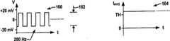
图7是用来说明通过图1至图6所示的具有多阶段测量周期的设备中的激励电路应用到所测量的电解质中的示例性激励波形的曲线图,其中该示例性激励波形包括用于电解质电阻测量的实质上无dc的200Hz方波、用于HDA和LPR测量的100Hz正弦波、以及无激励的ECN部分;7 is a graph illustrating an exemplary excitation waveform applied to a measured electrolyte by an excitation circuit in the apparatus having a multi-stage measurement cycle shown in FIGS. 1 to 6, wherein the exemplary excitation waveform includes A virtually dc-free 200Hz square wave for electrolyte resistance measurements, a 100Hz sine wave for HDA and LPR measurements, and an unexcited ECN section;
图8是用来进一步说明在电解质电阻测量的设备中所使用的实质上无dc的方波激励信号的曲线图;Figure 8 is a graph for further illustrating a substantially dc-free square wave excitation signal used in an apparatus for electrolyte resistance measurement;
图9A是用来说明在图1至图6所示的设备中使用动态激励幅值调节执行电解质(溶液)电阻测量(SRM)的示例性操作的流程图;9A is a flow chart illustrating exemplary operations for performing electrolyte (solution) resistance measurement (SRM) using dynamic excitation amplitude adjustment in the apparatus shown in FIGS. 1-6;
图9B至图9D是用来说明图1至图6所示设备在动态幅值调节过程中,对应于不同激励波形幅值的、关于方波激励电压和相对应地测量得到的平均电流的、电压的、以及电流曲线的曲线图;Figures 9B to 9D are used to illustrate the dynamic amplitude adjustment process of the equipment shown in Figures 1 to 6, corresponding to different excitation waveform amplitudes, about the square wave excitation voltage and the corresponding measured average current, Graphs of voltage and current curves;
图10A是用来说明以大约200Hz应用的示例性方波电压激励信号的曲线以及使用大约300毫秒的低取样周期取样的两个示例性同步A/D转换器取样信号的曲线图;10A is a graph illustrating a plot of an exemplary square wave voltage excitation signal applied at about 200 Hz and two exemplary synchronous A/D converter sampled signals sampled using a low sampling period of about 300 milliseconds;
图10B是示出了在图10A中的两个示例性取样时刻的激励电压和感应到的电流曲线的曲线图;FIG. 10B is a graph showing excitation voltage and induced current curves at two exemplary sampling instants in FIG. 10A;
图10C是用来说明在图1至图6所示设备中的在线电流放大器偏压(offset)测量的示例性操作的流程图;FIG. 10C is a flowchart illustrating an exemplary operation of an online current amplifier bias (offset) measurement in the apparatus shown in FIGS. 1 to 6;
图11是用来说明在图1至图6所示设备中具备HDA或LPR测量的动态算法变化的设备的操作流程图,其中包括对计算得到的B值的合理性测试;以及Figure 11 is a flow chart illustrating the operation of a device with dynamic algorithm changes for HDA or LPR measurements in the devices shown in Figures 1 to 6, including a plausibility test for the calculated B value; and
图12是用来说明图1至图6所示设备中的示例性偏压(offset)测量和HDA腐蚀测量的激励信号调节的流程图。FIG. 12 is a flow chart illustrating excitation signal conditioning for exemplary offset measurements and HDA corrosion measurements in the apparatus shown in FIGS. 1 to 6 .
具体实施方式Detailed ways
现在参考附图,下面结合附图对本发明的几个实施例或实施方式进行描述,其中在整个说明书中相同的元件使用了相同的附图标记,并且其中各个特征和曲线都不是按照比例绘制。本发明涉及可编程的低功率腐蚀测量现场设备,使用一种或多种高级的腐蚀测量手段来提供腐蚀测量和监视,提供电导值、常规腐蚀值、和/或局部化腐蚀值等,从而实时地执行腐蚀监视和/或离线腐蚀数据归档(log),而归档的数据可以在通过标准的4-20mA控制回路或其它通信装置连接的分布式控制系统中被使用,或是作为具有下载已存储的腐蚀数据到用户通信设备的独立(stand-alone)设备来操作。Referring now to the drawings, several embodiments or implementations of the present invention are described below in conjunction with the drawings, in which like reference numerals are used for like elements throughout the specification and in which various features and curves are not drawn to scale. The present invention relates to a programmable low-power corrosion measurement field device, which uses one or more advanced corrosion measurement methods to provide corrosion measurement and monitoring, providing conductance values, conventional corrosion values, and/or localized corrosion values, etc., thereby real-time Perform corrosion monitoring and/or offline corrosion data archiving (log), and the archived data can be used in a distributed control system connected through a standard 4-20mA control loop or other communication device, or as a stored Corrosion data to the stand-alone device of the user communication device to operate.
首先参考图1,下面根据本发明的一个或多个方面来描述一种示例性现场腐蚀测量设备2,该示例性现场腐蚀测量设备2包括具有下面将会详细描述的基于处理器的电子电路的发送头4、探针6、以及优选地由与安装了用来腐蚀监视/测量的该设备2的金属结构匹配的材料所制成的一组三个电极8,其中电极8浸入或是内嵌在溶液或其他电解的固体、气体或液体当中,其中溶液或其他电解的固体、气体或液体可以在安装结构中存储或是传送,这些安装结构诸如是管道、存储容器、或是其他所感兴趣的结构。发送器外壳4和探针6都是由环境保护性材料构成的,以便实现设备2的现场应用,诸如在线腐蚀监视以生成关于腐蚀速率的过程变量、局部化腐蚀指数(腐蚀局部化程度)、和/或电解质电阻(电导)。在操作中,探针6可以安装到感兴趣的结构上,并使电极延伸到管道内部或是流体腔室中以便暴露在内部的腐蚀过程中。Referring initially to FIG. 1 , an exemplary in-situ
如下面将会详细说明的,设备2可执行多种不同的与腐蚀相关的测量,包括测量极性电阻RP、溶液电阻RS、以及电化学噪声测量。线性化极性电阻(LPR)测量是一种适用于大多数情况的简单技术,其中对测试电极应用设定电压并且测量所得到的电流以便获得极性电阻Rp的值。随后通过Icurr=B/Rp从极性电阻RP(等于所施加的电压/流过的电流)计算腐蚀电流Icurr,其中B是Stem Geary常数。任何出现的大的溶液电阻Rs(与Rp串联地存在)以及关于B值的不确定都会影响LPR,LPR通常十分鲁棒(robust)并且不受噪声等影响,特别是在下面将会进一步详细描述的实施例中使用正弦波激励。谐波失真分析(HDA)直接地通过所获得的电流的谐波计算Icurr(如果所应用的电压是绝对的正弦波),并且不需要知道B值。由于来自LPR和来自HDA的Icurr理论上应该是相同的,因此可以基于已知的或是测量到的Rp通过HDA运算所使用的谐波信息来计算B。HDA还受到溶液电阻Rs的影响,趋于“线性化”响应,其中谐波失真是非线性的Rp而不是与Rp串联存在的Rs所造成的。由于谐波处在低电平,来自HDA的测量结果(Icurrharm)会受到从一个测量到另一测量的噪声的干扰,如果从噪声Icurr和从Rp计算B值,则计算得到的B值也会有噪声。为了解决这种情况,需要对用来计算Icurrharm的值进行滤波或是取平均,但是这将会降低设备2的响应时间并且抑制检测腐蚀侵扰改变的能力。为了实现上述挑战性目标,设备2(从Rp和Icurrharm)计算每次测量得到的瞬时B值,并且通过数字低通滤波来对B的波动取平均,其中可以与瞬时Rp一起使用滤波后的计算得到的B值来计算Icurr。SRM、LPR、以及HDA等所有扰动技术提供了测试电极的平均腐蚀速率并且对于局部化腐蚀都不非常敏感。然而,在设备2中ECN也是可行的,其提供了一种非扰动的测量技术(不使用外部应用的激励),以提供任何局部化腐蚀的指示。此外,ECN可以检测电化学引起的局部化侵蚀(凹坑、狭缝腐蚀等)以及由对测试电极上形成的任何保护性氧化膜的机械损伤引起的局部化侵蚀,这些机械损伤诸如气蚀损伤、腐蚀损伤、应力腐蚀破裂等。As will be explained in detail below, the
参考图2,示意性地描述了发送器的电子电路4,电子电路4包括具备电隔离(galvanic isolation)和内部安全(IS)屏蔽电路12的回路接口10、以及向内部设备提供来自控制回路11的电流或是可选地来自电池13、太阳能板(未示出)或其他电源的电能的电源系统14,其中设备2通过内部安全(IS)屏蔽电路12与标准4-20mA控制回路11接口。回路接口10进一步包括可操作地与数字系统20的处理器22和控制回路11相连接的通信接口16,从而允许处理器22使用HART或其他通信协议与外部通信设备(未示出)进行通信,以此用户可以对设备2进行设置或者编程和/或可以从设备2获取已存储的计算得到的与腐蚀相关的值。此外,示例性回路接口10包括用来控制回路11中的电流所专用的数字模拟转换器(DAC)10,从而允许处理器22控制回路中的电流以指示通过测量/计算得到的过程变量(例如,对应于腐蚀速率、局部化腐蚀指数、电导等的4至20mA之间的回路电流级),并且还提供了FSK或其他类型的回路电流调制以便根据诸如HART等适当的协议经由回路11或其他有线或无线通信装置执行数字通信。Referring to FIG. 2, the electronic circuit 4 of the transmitter is schematically described, the electronic circuit 4 includes a loop interface 10 with electrical isolation (galvanic isolation) and an internal safety (IS) shielding
设备2还包括具有处理系统22的数字系统20,该处理系统22可以是诸如微处理器、微控制器、数字信号处理器(DSP)、可编程逻辑器件等任何形式的处理电路,通过处理系统22可以实现上面所述的各种功能。数字系统20包括一种或多种形式的存储器24,尤其是诸如闪存、FRAM等非易失性存储器,并且数字系统20可包括模拟数字转换器(A/D)26,其中A/D 26和/或存储器24可以是独立的部件或电路,或是可以集成在处理器22当中。The
此外,腐蚀测量设备2还包括含有信号调节电路34的探针接口系统30,以便与处在要测量的电解质中的多个测量电极8接口。此外,在所说明的实施方式中,探针接口30还包括用来产生通过信号调节电路34应用到执行下面将会详细说明的特定类型测量的至少一个电极8上的激励信号的第二DAC 32,其中激励DAC 32可选地处在数字系统20当中或是集成到处理器22当中。信号调节电路34包括用来根据DAC 32经由第一电极E1(还被称为辅助电极)向电解质的输出提供激励信号的激励电路34a、以及用来经由一个或两个其他电极E2和/或E3来提供感应诸如电压、电流等一个或多个与腐蚀相关的电信号的感应电路34b,其中第二电极在这里被称为用来感应关于腐蚀速率的电流信号的参考电极或工作电极,其中参考和/或辅助电极E2、E1可以是由惰性材料制成的。此外,信号调节系统34还包括具有多个模拟开关部件的开关系统34c,这些模拟开关部件实现了激励电路34a、感应电路34b中的各个部件的、以及多种配置下的电极8的受处理器控制的再配置。Furthermore, the
参考图3A、图3B和图4,描述了探针接口系统30和数字系统20的特定部件的进一步细节,在图3A中包括激励电路34a、感应电路34b、以及包含标记为U13至U16的四个模拟开关器件34c的开关系统。模拟开关U13至U16中的每一个都具有两种开关状态,在图中表示为“0”状态和“1”状态,其中处理系统22提供了相对应的开关控制信号CS13至CS16以控制每个开关34c的状态。此外,模拟开关U13至U16还具有受芯片选择输入(未示出)控制的第三操作状态,其中开关端子都断开与极端子(pole terminal)的连接。因此连接开关U13至U16以实现受处理器控制的激励及感应电路34a和34b中的部件互连来再配置腐蚀测量设备2成多种不同的腐蚀测量设置,其中图4示出了用来说明设备2的SRM、HDA、LPR、电池偏差电压、以及ECN测量操作等下的开关设定或状态的表70。用户可对示例性设备2进行编程以便在图4所示的任何一种单一的测量模式下操作,或是在一系列设备周期的每个周期中通过组合两种或是更多的所列测量类型来执行测量,从而可实现腐蚀发送器2适应于任何一种腐蚀测量或监视应用。在这个方面,通过使放大器和其他部件的个数最小,回路接口30在由回路或电池电源施加的严格功率约束的阻抗和准确性方面上实现了信号调节电路与电极8的最优互连,同时还提供了在单独的用户可编程设备2中使用ECN、HDA、SRM、LPR和偏压(offset)来执行腐蚀测量及监视方面上的先进性能。Further details of certain components of
处理器22在每个测量周期中都控制激励DAC 32以便分别地经由激励电路34a、第一(辅助)电极E1、以及开关系统34c提供对该单元的适当激励,并且还经由感应电路34b、开关34c、以及参考及工作电极E2和E3来操作测量A/D 26以实现对电池(cell)电压和/或电流的相关测量。利用形成与激励及感应电路34a和34b连接的电阻R49至R51以及滤波网络R54至R56、C56、C57和C58,经过探针6形成了电极耦合。在下面所描绘的情况中,设备2在每个设备周期中通过器件U13至U16的受控开关来执行一系列测量。此外,在所说明的设备2中,特定的可选择测量类型(例如,SRM、HDA、以及LPR)涉及激励信号的应用,而其他类型(例如,ECN)则不涉及激励信号的应用,其中使用HDA或LPR测量类型来计算常规腐蚀,使用SRM技术来测量电解质电阻或电导,并且使用ECN测量来计算局部化腐蚀指数值。通常的,按照第一极性或是按照相反的第二极性,作为由DAC 32提供的电压信号对辅助电极E1应用(任何的)激励信号,其中该第一极性使用第一放大器(例如,运算放大器)U12A直接地经过开关U13的“0”状态路径,而该第二极性经由逆变器配置的放大器U12B经过开关U13的“1”状态,并且驱动放大器U10A经过开关U16的“0”状态路径和电阻R61向辅助电极E1提供对应的输出电压。此外,在这些配置中,电极处在激励电路34a的驱动放大器U10A的反馈回路中,因而辅助和工作电极E1和E3之间的电流流动会引起参考电极E2和工作电极E3之间的电势与所应用的激励信号电压相等。此外,在特定的操作配置中,还可以不应用激励,其中开关系统使得辅助电极E1与激励电路34a电隔离,而处理系统22通过感应电路34b对E2和E3上感应得到的电压信号进行取样。
从任何应用的激励电压信号得到的回流电流流过示例性的三个电极恒电势(potentiostatic)测量配置中的工作电极E3,其中感应电路34b经由形成流向电压转换器的电流的、具有在流向电压转换器的电流的反馈路径上的限流电阻R57的电流感应放大器U9A来感应上述电流,如此限流电阻R57(例如,1千欧姆)不会影响电流的感应操作。流向电压转换器的电流所经过的电阻R57对电流路径引入了接近零的电压降,可以选择电阻R57的值来提供根据需求的增益、高信号灵敏度、以及宽的动态范围,以便保护U9A对负载的倒相输入(inverting input),并且电阻R57处在U9A的反馈回路当中从而消除了电阻R57对电流测量的影响。使用这种感应电路34b的、流向电压转换器的电流来感应HDA和ECN测量中的电流,并且还与同步整流器一同使用以测量极性电阻LPR。The return current derived from any applied excitation voltage signal flows through the working electrode E3 in an exemplary three-electrode potentiostatic measurement configuration in which the
流向电压转换放大器U9A的电流对应于开关U15的“0”和“1”状态分别提供了放大器U8A的倒相输入的输出或是非倒相输入的输出,其中U8A的输出提供了用于电流感应的、流向A/D转换器26的两个输入中的一个。电流感应极性开关U15因此作为整流器来操作从而实现了特定的测量类型,以便实现受来自处理器22的控制信号CS15控制的拨动开关(toggled switch)。在这个方面,当激励极性开关U13和电流感应极性开关U15同步地操作时(通过处理器22对控制信号CS13和CS15的开关进行控制),这些模拟开关部件构成了在用来测量电解质(溶液)电阻RS的特定实施例(SRM模式)中使用的同步整流器。此外,在腐蚀测量设备2执行HDA、LPR、以及ECN测量中,无需扳动用来测量来自工作电极E3的感应电流的极性开关U15即可使用电流感应部件。利用放大器U7A驱动第二模拟输入以便经过高阻抗路径R59感应参考电极E2处的电压,感应电路34b进一步提供了电压感应能力,并利用放大器U5A来比较参考电极E2处的电压和参考电压VREF 31。The current flow to voltage translation amplifier U9A provides the output of the inverting input or the non-inverting input of amplifier U8A corresponding to the "0" and "1" states of switch U15, where the output of U8A provides the output for current sensing. , to one of the two inputs of the A/
因此,A/D 26可在处理器22的控制下获得并且转换模拟电压和电流值,并且随后向处理器22提供关于这些测量的数字量。此外,A/D转换器26还可以是任何合适的转换设备,诸如一个实施例中的基于delta-sigma调制器的转换器,并且优选地在相当低的转换速率下操作。例如,如此操作A/D 26以便在大大低于激励信号频率的取样速率(诸如低于大约每秒10次取样)下获得与各种腐蚀相关的感应信号的测量取样,例如在一个实施例中每300毫秒取样一次,从而维持在由回路或电池供电的实施方式中的电源系统14的电能预算之下。因此,处理系统22可操作地与探针接口系统30耦合以便通过激励电路34a控制提供给电解质的激励信号,并且提供控制信号CS13至CS16给开关系统34c来选择性地再配置开关部件U13至U16,以便基于来自感应电路34b的所接收到的测量值来执行多种不同类型的腐蚀测量并且计算至少一个腐蚀相关值。Thus, the A/
因此,除了支持HART通信的4-20mA回路接口之外,发送器的电路4还提供了经由探针6对电极8的激励信号的应用、对于感应得到的电极信号的调节、模拟数字转换电路26、以及处理部件22,其中该处理部件22可控制激励信号的应用,获取信号测量,并且执行信号分析以产生腐蚀速率、电解质电阻或电导、和/或局部化腐蚀指数等过程变量。设备2可被配置用来产生代表过程变量的控制回路11中的4-20mA信号,其中过程变量可以是表示正在进行中的通常连续的腐蚀过程的当前速率的、单位为每年多少密耳或毫米的常规腐蚀速率、电解质电阻或电导值、或是无单位的并且代表具有低腐蚀速率的过程中发生局部化腐蚀的程度的量度的凹陷(pitting)或局部化腐蚀因子,但是这样的局部化腐蚀会导致降低材料强度的、管道或储罐材料中出现的、小的并且最终是深的洞。还可以配置设备2周期性地或是响应从回路11中的另一控制实体或用户通信设备请求得到的数据,通过数字通信来报告上述这些值中的一个或多个。Therefore, in addition to the 4-20mA loop interface supporting HART communication, the circuit 4 of the transmitter also provides the application of the excitation signal to the
现在参考图1至图3B,设备2包括用来提供从4-20mA回路隔离开电极E1至E3和设备2的电路的隔离及内部安全(IS)屏蔽12。如图3B所示,来自4-20mA回路11的电流流经具有保险丝F1的初级安全区(primary safetyarea)12a的输入级、电涌保护器N1和电阻R3和整流器12a1、以及紧跟的用来提供隔离变压器T1的输入的逆变器12a2。变压器T1的隔离输出提供了次级隔离区(secondary isolated area)12b的输入,该次级隔离区12b包括由稳压齐纳管N6至N9组成的电压保护电路12b1、以及由晶体管P5至P8和电阻R17、R21、R29至R30、R34、R35和电容C34组成的限流电路。第一内部安全屏蔽级的输出提供了第二IS屏蔽级12c的输入,该第二IS屏蔽级包括另外的稳压齐纳管N10至N15,从而进一步限制通过回路控制器电路15所监视的可能电压。设备2的IS保护还提供了1千欧姆的保护电阻R57至R61以保护电极E1至E3。在操作中,测量到的电解质和电极E1至E3典型地接地,因而探针接口电路30的前端也通过低阻抗路径接地。隔离电路12,特别是隔离变压器T1的提供,减轻了或是避免了潜在的经过4-20mA控制回路11的接地回路问题,其中多个设备都安装在同一储罐或管道中。因此,无需外部隔离部件即可使用设备2,从而节省了安装成本。此外,隔离变压器T1还可构成示例性整体防爆炸(内部安全或IS)屏蔽中的部件。这种两级IS电路12b和12c允许在无需外部IS电路即可提供内部安全的应用中使用设备2,从而进一步降低安装成本。例如,在这些应用中,(例如,美国)使用具有防爆炸证明的罩(enclosure)来构成外壳4(图1)或是欧洲使用标记为“EX d”的外壳4,并且设备2中的内部IS电路的提供允许设备2连接到非IS回路11上。以这种方式,无需使用额外的屏蔽,示例性设备2即可有效地将Ex d或防爆炸安装方法“转变”成对于电极8和探针6(图1)的保护。Referring now to FIGS. 1-3B , the
参考图5至图7,在操作中,如图5所示,与在传送电解质50的管子或其他金属结构40中浸没的电极8一起安装探针6,其中电极可以是任何几何形状的,包括嵌入式安装(flush mounted)并且无需彼此处在一条线上,其中图5仅仅是示意性的。图6示出了电极中的其中一个E1和图5所示装置中的需要测量的电解质50的等效电路60,其中其它电极E2和E3的电路都与图6所示的电路相等同。如图6所示,电极/电解质电路60包括内部电池电压(internal cell voltage)Vc和极性电阻Rp的串联组合,而在电极E1与电解质50之间该串联组合又与电化学双层电容Cdl并联连接,其中电解质50具有作为SRM测量对象的电阻Rs。如图7中的激励信号曲线图100所示,在三个测量阶段101、102、103中利用一种可能配置的发送设备2执行信号测量,其中三个测量阶段101、102、103可选地在一系列设备周期的每一个中可以以任何顺序设置,或是可编程设备2在每个设备周期都只执行一种测量,或是在给定的设备周期中执行两种或更多类型测量的组合。在这种配置下,开始时可进行SRM测量以提供溶液电阻值Rs,随后在LPR或HDA测量中再使用电阻值Rs来确定腐蚀速率以校正极性电阻Rp的运算中出现的任何误差,而上述这些电阻Rs和Rp在图6中实质上是串联的。Referring to FIGS. 5-7 , in operation, as shown in FIG. 5 , the
在图7所示的示例性配置的第一测量阶段101中,初始地在周期100a中操作同步整流器以执行下面将会进一步描述的偏压(offset)测量,之后在周期100b中动态地调节AC激励信号的幅值。之后在部分101中应用相对高频的ac激励信号以执行溶液电阻/电导测量,之后紧跟着间隔100c以测量由于非相同电极8导致的不平衡所造成的偏压(offset)。此外,在第一阶段101中,设备2还有利地应用均值为零的AC波形(实质上无DC偏压(offset))以避免极性化工作电极接口。此外,在示例性设备2中,在低速下操作DAC 32和处理器22(为了节约电能),其中SRM期间的DAC输出被设定为给定的dc电平并且使用开关系统34c来切换输出极性以产生用于SRM测量的双极性方波激励信号。为了最小化在阶段101中由于SRM测量可能产生的小DC电池(cell)电流的影响,将阶段101的持续时间设定得尽可能短并且在阶段102的LPR测量之前紧跟SRM测量之后无需极性化即可提供间隔周期100c,从而允许去除工作电极接口的极性。In the
在第一阶段101中,使用高频方波激励来测量电解质(溶液)电阻Rs(电解质电导是1/Rs)。在第二部分102中,设备2应用较低频率的正弦波激励电压并且测量电流和相关的谐波,以便使用LPR和/或HDA技术来确定腐蚀速率。在第三部分103中,没有应用激励,并且该设备使用ECN测量方法测量出电化学噪声以便确定局部化腐蚀指数。In a
在设备周期的第一部分101中,处理器22使得开关系统34c按照图4所示的表70中的SRM行来配置开关U13至U16,其中U14和U16处在开关状态“1”并且在处理系统22的控制下通过同步地扳动开关U13和U15来操作同步整流器以提供频率小于大约500Hz的、优选地频率为大约100至200Hz之间的方波激励/电流感应整流器,其中图7中的曲线图100示出了在第一测量阶段101中以大约200Hz的频率下的操作。值得注意的是在图6所示的等效电路中,相对高频(例如,高于大约50Hz)的应用将会由于电容Cdl而有效地缩短上端支路(upper leg)的长度,其中经由工作电极E3感应得到的AC电流将会倒相地与电解质电阻Rs成比例。还可在SRM测量中使用诸如正弦波、方波等其他波形。在阶段101中所描述的SRM测量涉及在辅助电极E1处提供正弦波激励电压并且一并地通过工作电极E3处感应得到的电池(cell)电流的感应电路34b和A/D 26执行测量,其中DAC 32(图3A)提供了利用可交变所应用的激励电压的极性的U13的开关而受处理器22控制的等级下的DC输出信号,所应用的激励电压处在经由控制信号CS13通过处理器22控制的激励频率下。在工作电极E3处感应得到的电池(cell)电流也是激励频率下的方波。处理器22还经由CS15操作电流感应极性开关U15以便在相同频率下扳动开关,因而可以整流感应得到的AC电流信号以向A/D转换器26提供整流后的输入信号。为了节省电能,处理器22控制A/D转换器26在非常低的频率下取样,例如在一个实施例中频率大约是3.3Hz。因此处理器222可获得关于感应电流的多次读值并且对这些读值取平均以便计算随后用来计算电解质电阻Rs的平均感应电流。In the
参考图8,同步整流器的操作允许向辅助电极E1提供实质上无dc的激励信号从而不会恶化电池(cell)中的腐蚀,经由U15对感应电流信号的整流允许A/D转换器26在低取样速率下操作从而节省了电能,而进行了足够多次数的取样又允许处理系统22可获得精确的平均电流值,其中倘若不进行上述整流,平均电流值则会是零或接近零。在这个方面,值得注意的是对辅助电极的dc电压的应用会改变被测量的腐蚀过程的电化学特性,并且因此会干扰任何随后进行的腐蚀速率测量。此外,通过将上述dc成分斩波(chop)成均值为零的ac成分,对于电流感应电路的整流将会有效地消除会导致非相同电极8出现的感应电流中的任何dc。此外,还可在除开关频率之外的其他频率下操作以排除干扰。图8描述了一种通过DAC 32和同步整流器的操作在第一测量阶段101期间可能应用的实质上无dc方波激励信号波形,波形的幅值大约是+/-20mV,其中图3A所示的DAC 32提供了用来通过扳动开关U13来切换极性的实质上恒定的dc值以在辅助电极E1处产生激励波形。因此,设备2有利地在第一测量阶段101中提供了无干扰的、无dc的方波激励信号,同时还提供了在执行SRM测量时实现对感应电流慢速取样的同步整流,从而使得回路或电池电能消耗保持在电能预算之下并且还消除了dc和噪声。Referring to FIG. 8 , operation of the synchronous rectifier allows providing a substantially dc-free excitation signal to the auxiliary electrode El so as not to worsen corrosion in the cell, rectification of the induced current signal via U15 allows the A/
参考图9A至图9D,设备2优选地在预定时间周期时,或是在每个SRM测量阶段101的开始时,调节SRM测量中的方波激励信号的大小或幅值。这方便了改进A/D转换器22的输入范围,从而方便了改进测量电流取样和计算得到的平均电流值等的准确性,并且因此方便了电解质电阻(或电导)测量。图9A所示的处理120描述了这个示例性操作,其中SRM阶段101开始于122并且在124以第一个(例如,低的)峰值到峰值的幅值向辅助电极E1提供相对高频率的方波激励信号。在一个实施例中,方波频率大约是200Hz,尽管还可使用其他值,优选地小于等于大约500Hz。图9B至图9D描绘了根据图9A所示的处理120在不同激励波形幅值下方波激励电压的电压和电流曲线与相对应地测量得到的平均电流的曲线图140、144、150、154、160和164。在图9B所示的第一曲线140中,在相对低的第一幅值142下应用大约200Hz的方波。在处理120中的126测量平均电流,例如,如上所述利用同步整流器操作,通过A/D 26执行多次测量,或是使用其他适当的技术来测量平均电流值。在128作出确定由此获得的平均电流值是否超过了预定阈值TH,其中可以使用任何适当的阈值,通过这样的阈值可以做出关于A/D输入范围的最优使用的决定。在一个示例中,阈值可以是A/D输入范围的大约一半,尽管还可使用其他值。Referring to FIGS. 9A to 9D , the
如果测量得到的电流没有超过阈值TH(128中的否),则如图9B的电流曲线144所示,在130中增大激励信号幅值(例如,在处理系统22的控制下增大DAC 32的输出),并且图9A中的处理120再次返回到126以测量平均电流。图9C中的曲线150和154示出了这种情况,其中新的激励信号幅值152大于图9B中的初始幅值。在128中新的平均电流与阈值TH进行比较,并且如图9C中的曲线154所示,此电流仍低于阈值TH。相应地,图9A中的处理120在130中再次将激励幅值增大到图9D所示的激励电压曲线160中的电平162。在这个点上,如图9D的曲线164所示,最新的激励幅值162提供了大于阈值TH的感应得到的平均电流(图9A所示的128中的是),并且图9A中的处理120前进至132,在此使用最新的激励电压幅值来计算电解质电阻Rs,并且在134中结束阶段101中的SRM处理。以这种方式,腐蚀测量设备2适用于利用整个A/D转换范围,其中处理系统22使已知的最新激励电压幅值与在132中最新测量且计算得到的平均电流值相互关联,以便计算电解质电阻Rs和/或电解质电导。这种激励幅值的自适应调节方便了可行的A/D分辨率的最优使用,并且设备2无需牺牲准确性即可适用于具有非常低或非常高的电解质电导性的应用。If the measured current does not exceed the threshold TH (No in 128), then as shown in the
参考图10A至图10C,设备2还提供了对于电流放大器偏压(offset)的校准以进一步提高计算得到的腐蚀相关值的精度。在这个方面,与同步A/D取样一并使用如上所述的同步整流器则会导致如图10A和图10B所示在方波的每个周期内测量得到的电流和A/D转换器26的输入都会略微增大的情况出现。图10A中的曲线170描绘了在SRM测量中使用的200Hz方波电压激励信号,同时示出了使用大约300毫秒的长A/D取样周期在时间T1和T2分别得到的两个示例性同步A/D转换器取样S1和S2。图10B中的曲线图172和174分别示出了在图10A中的两个示例性取样时间T1和T2处的激励电压和感应到的电流曲线的示例性部分的进一步细节,其中可以看出的是第一电流取样S1比第二电流取样S2略小,这仅是由于它们是在激励周期当中的不同点执行取样的。除了这些误差(inaccuracy)之外,用来感应电流信号的运算放大器U8A和U9A中的偏压(offset)会导致Rs、腐蚀速率、和/或局部化腐蚀等运算中的精度。其余误差还来自整流器的逆变路径与非逆变路径之间的dc偏压(offset)值、单元(cell)驱动放大器U10A的一定的速度、以及与探针输入相关的电阻和电容。Referring to FIGS. 10A to 10C , the
为了减小上述误差,设备2提供了使用如图10C所示的开始于182的处理180执行在线电流放大器偏压(offset)测量,经过处理180,设备2基于测量得到的电流放大器偏压(offset)自动地确定在线偏压(offset)值,同时通过处理器22扳动(toggle)同步整流器部件。在184中,处理器22使得DAC32将激励信号设定成零,并且分别经由信号CS13和CS15开始扳动同步整流器部件U13和U15,在184中,没有应用激励电压,其中经由信号CS13和CS15以如上所述的SRM测量中一般使用的相同速率(例如,在一个实施方式中以大约200Hz)来切换整流器部件。在190中,处理器22获取在188中使用A/D 26感应得到的电流信号的多个取样并且计算平均电流值,随后将该平均电流值存储以备后续作为如上所述的SRM测量中的偏压(offset)来使用,并且在192中结束该在线电流放大器偏压(offset)测量。之后在阶段101中执行的SRM测量期间,在计算电解质电阻值Rs之前处理器22使用已存储的偏压(offset)来校正电流读取值,从而抵消包括放大器U9A和U8A的电流感应电路中偏压(offset)带来的不利影响并且补偿与同步整理器操作和A/D转换器26的同步取样相关的取样误差。In order to reduce the above-mentioned errors, the
现在参考图3A、图3B、图4、图7和图11,设备2还提供了改进类型的HDA和/或LPR测量,其中图4示出了与图3A中的U13至U16的开关状态相关的模式下的开关系统配置。因此可配置设备2以使用LRP或HDA技术计算常规腐蚀速率ICORR。基本LPR测量典型地采用默认值或用户输入的B值,相反地HDA方法涉及根据测量得到的电流谐波同时计算B值和腐蚀速率。然而,本发明的发明人已经意识到传统的HDA计算方法并不是对于所有的腐蚀应用都适用或都是鲁棒的,其中根据使用测量得到的电流谐波和电解质电阻执行的在线合理性(plausibility)测试的结果来操作设备2以选择性地采用上述技术(HDA或LPR)中的其中一个。Referring now to Figure 3A, Figure 3B, Figure 4, Figure 7 and Figure 11,
图7中的第二示例性测量部分102描述了在这部分102应用的激励,其中经由在电流谐波的LPR或HDA类型测量中使用的辅助电极E1,对该单元应用低频的正弦波激励电压。在上述这些测量类型中,正弦激励信号优选地处在大约50mHz或更高的激励频率下,以便无需不恰当地延长设备周期时间即可实现对于超出大于一个周期的激励信号的电流取样的测量。因此,在特定的优选实施例中,在大约100至200mHz的激励频率下提供激励信号,其中图7中的示例使用了大约100mHz的激励频率。此外,利用谐波失真分析或第二阶段102中的LPR,优选实施例中的处理系统22基于大于十个周期的(优选地是20个周期的)感应得到的正弦电流信号来计算腐蚀相关值。因此,与用来在单个周期上利用10mHz的应用激励测量电流信号的传统设备相比较,上面描绘的设备2提供了可在处理系统22中利用在大于单个周期上获得的数据执行分离傅立叶变换的改进能力,从而提高了关于所得到的腐蚀相关值的计算精度。在这个方面,使用大约100mHz的示例性激励频率在大约20周期上对电流信号执行取样带来了显著的改进,却仅对HDA或LPR测量的第二测量阶段102的持续时间带来了很小的提高。The second
在图7的第二阶段102中,低频正弦激励会产生具有多个频域分量的所得到的感应电流信号,这些频域分量包括在处理器22的腐蚀相关值运算中使用的激励频率下的基波分量、二次谐波分量、以及三次谐波分量。通过对感应电流信号进行取样以得到上述谐波信息并且通过A/D 26将这些谐波信息转换成数字化数据,利用处理系统22执行分离傅立叶变换(DFT)以生成感应电流的频域下的频谱。如上所述,设备2的示例性实施例在超过一个激励周期上取样感应电流信号,并且优选地使用大于大约50mHz(优选地使用大约100至200mHz)的激励频率,从而不会不恰当地延长设备周期时间,尽管本发明并不局限于这些具体的示例。从DFT频域频谱中,获取基波和各种谐波的幅值,并且在计算腐蚀速率中使用谐波测量数据。此外,在一个可能的实施方式中,与正弦波激励电压的生成一致地计算DFT,其中通过由DAC 32(图3A)执行的一系列次级步骤,由处理系统22的存储器查询表或存储器24(图2)利用相同的DFT运算中所使用的查询表生成正弦激励电压。在这个方面,示例性表在每个周期都执行96个步骤以保持该表的大小尽可能的小,并且还允许用2、3和4对其分割。In the
在所描述的示例中,通过使电流取样值乘以来自查询表的合适的数,来‘速度非常快’地执行DFT。进一步,示例性DFT运算还计算各谐波中的实分量和虚分量,并且由于与选择实分量和虚分量的其中一个相比减小对噪声的灵敏度而使用模数(modulus)作为实分量和虚分量的和的平方根(例如,(实分量2+虚分量2)1/2)。在各离散的正弦阶跃(sine step)之后通过使A/D值乘以来自正弦查询表的合适值,并且将乘积加到合适的加法器变量来计算基波、二次谐波、以及三次谐波,其中这种方法降低了对于立即数存储的需要。优选地,使用电阻分压器R52、R53来分级DAC 32的输出以便减小最小的单个微小台阶(bit step)的大小,其中可优选地选择R52和R53的值来覆盖电压偏压(celloffset)可能的最宽范围,同时最小化单个微小台阶的大小,并且处理系统22可确保电池(cell)偏压和/或所需的扰动幅值不会超出可使用的范围。进一步,在所描述的实施例中,还提供了时序延迟以实现电池(cell)电流的正弦输出中台阶改变的效果,从而将前面的传递给由A/D 26执行的电池(cell)电流感应/测量。In the example described, the DFT is performed 'very fast' by multiplying the current samples by an appropriate number from a look-up table. Further, the exemplary DFT operation also calculates the real and imaginary components in each harmonic, and uses the modulus as the real and imaginary components due to the reduced sensitivity to noise compared to selecting one of the real and imaginary components. The square root of the sum of the imaginary components (eg, (real component2 + imaginary component2 )1/2 ). The fundamental, second harmonic, and cubic Harmonics, where this approach reduces the need for immediate storage. Preferably, the output of the
优选地选择小于腐蚀处理的典型时间常数(例如,与Rp并联的Cdl)的激励频率,但对于从大于一个激励信号周期中获取数据的合理测量时间而言仍足够高。在这个方面,以较高频率在相当多个数的周期中取样会减少取样中断(discontinuity)的次数。例如,在发生了相当缓慢的信号漂移(signal drift)的情况下,如果仅在单个周期中获取数据,则会取样得到中断(例如,第一取样与最后取样之间的差异),其中上述中断会引起傅立叶光谱中出现过多的谐波成分,从而不利地影响HDA测量技术。此外,在多于一个周期中取平均可提高对于干扰和噪声的抗扰性(immunity)。The excitation frequency is preferably chosen to be smaller than the typical time constant of the etch process (egCdl in parallel withRp ), but still high enough for a reasonable measurement time to acquire data from more than one excitation signal period. In this regard, sampling at a higher frequency over a substantial number of cycles reduces the number of sampling discontinuities. For example, in the case of fairly slow signal drift, if the data is only acquired in a single cycle, the samples get interrupted (e.g., the difference between the first sample and the last sample), where the interrupted This can cause excessive harmonic content in the Fourier spectrum, adversely affecting the HDA measurement technique. Furthermore, averaging over more than one cycle improves immunity to disturbances and noise.
在所描述的实施方式中,处理系统22使用测量阶段102中获得的谐波数据在每个设备周期中评估下列方程式(1)至方程式(3)以计算腐蚀电流Icorr,并且从腐蚀电流Icorr确定腐蚀速率:In the described embodiment, the
BHARM=(Icorrharm*Sine Amplitude)/I1)-(RS*Icorrharm) 方程式(2)BHARM =(Icorrharm *Sine Amplitude)/I1 )-(RS *Icorrharm ) Equation (2)
Icorr=((BHARM OR BUSER)*I1)/((Sine Amplitude)-(RS*I1)) 方程式(3)Icorr =((BHARM OR BUSER )*I1 )/((Sine Amplitude)-(RS *I1 )) Equation (3)
其中I1是感应电流的基波分量,I2和I3分别是二次谐波分量和三次谐波分量,Sine Amplitude是在阶段102中应用的正弦激励电压信号的幅值,并且B是以伏特为单位的特定应用中的腐蚀处理值。一旦计算得到腐蚀电流Icorr,就将其乘以与特定电极大小相关的常数、法拉第常数、以及材料的原子量,以便计算以每年多少毫米或密耳为单位的腐蚀速率。whereI1 is the fundamental component of the induced current,I2 andI3 are the second and third harmonic components, respectively, Sine Amplitude is the amplitude of the sinusoidal excitation voltage signal applied in
参考图11,示例性腐蚀测量设备的另一特征是基于测量得到的电流谐波I1、I2和I3计算B值BHARM并且基于计算得到的BHARM值和运算得到的电解质电阻Rs来选择性地使用LPR或HDA算法。在这个实施例中,如果可能即执行HDA测量和运算,并且如果在给定的设备周期中基于一个或多个合理性测试而怀疑HDA结果,则处理系统22改变成LPR类型测量。特别地,设备2自动地执行三种类型的测试中的一种或多种以确定是否保证HDA运算正确并且选择性地将该算法改变成高电解质电阻状态或表示HDA测量中可能会出现误差的其他条件下的LPR。Referring to FIG. 11 , another feature of the exemplary corrosion measurement device is the calculation of the B value BHARM based on the measured current harmonics I1 , I2 and I3 and based on the calculated BHARM value and the calculated electrolyte resistance Rs to selectively use the LPR or HDA algorithm. In this embodiment, HDA measurements and calculations are performed if possible, and if the HDA results are doubted based on one or more plausibility tests in a given plant cycle, the
图11示出了在202开始如上图7所示的示例性设备周期中的第二阶段102的动态改变HDA/LPR的处理200,其中处理器22使得DAC 32和激励电路34a在204中向辅助电极E1提供正弦激励信号,并且在206中使用A/D转换器26通过感应电路34b测量工作电极E3处感应得到的电流信号。处理器22在208中执行DFT以识别电流谐波I1、I2和I3,并且随后在210中执行一个或多个测试以确定是否可以执行HDA腐蚀测量。特别地,在212中作出量(2*I1*I3-I22)是否为正值。如果不是正值(在212中的“否”),则由于被测试量(2*I1*I3-I22)的平方根出现在上述方程式(1)的分母而视为不能执行HDA类型的测量。处理200前进至图11中的230,在230中处理系统22获得默认值或是用户提供的B值BUSER,并且在232中将这个BUSER应用到上述LPR腐蚀电流方程式(3)中以计算当前阶段102中的ICORR,随后在240中结束上述循环。11 shows a
然而,如果发现第一被测试量(2*I1*I3-I22)是正值(在212中的“是”),处理200前进至214,并且在214中作出电解质电阻Rs与极性电阻Rp相比较的相对大小的判断以确定是否可以正确地测量谐波,其中大的Rs趋于线性化引起低谐波水平的电池(cell)响应。在所述实施例中,在214中对量(Rs/(Rs+Rp))与诸如在一个示例中大约0.1的阈值进行比较,并且如果小于阈值(在214中的“否”),则处理器22判断HDA是有问题的并且在前进到216之前在215中设定标志。如果214中的测试没有指示大的Rs的出现(在214中的“是”),则处理前进至在216、218中执行的第三测试,其中处理系统22在216中通过使用测量得到的电流谐波I1、I2和I3评估上述方程式(1)和方程式(2)以计算ICORRHARM和BHARM并且低通滤波器对计算得到的B值BHARM进行滤波。在所述示例中的计算得到的B值BHARM是数字化低通滤波过的(例如,移动平均线(moving average)或由处理器22执行的其他低通类型的数字化滤波),以便去除瞬时波动和非法读取值,因此提高在测量得到的谐波具有非常小幅值的状态下的设备灵敏度。However, if the first measured quantity (2*I1 *I3 −I22 ) is found to be positive (“YES” at 212 ),
随后在218中确定计算得到的B值BHARM是否处在所指定的假定为介于最小值BMIN与最大值BMAX之间的有效范围内,诸如在一个示例中介于大约10-60mV之间(例如,或是对于水溶液电化学而言合理的其他公知的范围)。值得注意的是,对于计算得到的B值BHARM的示例性低通滤波,诸如移动平均数(moving average)或是其他数字滤波器,有利地被操作以去除任何类型的短时波动和偶尔的无效读取,因此通过使用滤波后或平波后的计算得到的B值可以在低幅值谐波状态方面提高设备的灵敏度。在一个实施例中,通过(1-X)*BHARM(n-1)+X*BHARM(n)计算滤波值BHARM,其中在一个实施方式中X是大约0.05。如果BHARM不处在测试范围之内(在218中的“否”),则HDA技术就值得怀疑,并且处理200前进至如上所述的230和232。否则(在218中的“是”),在220中处理系统22利用HDA技术通过用计算得到的B值BHARM来评估上面的方程式(3)以计算腐蚀电流。It is then determined in 218 whether the calculated B value BHARM is within a specified valid range assumed to be between a minimum value BMIN and a maximum value BMAX , such as between about 10-60 mV in one example (eg, or other known ranges that are reasonable for aqueous solution electrochemistry). It is worth noting that an exemplary low-pass filtering of the computed B-value BHARM , such as a moving average or other digital filter, is advantageously operated to remove short-term fluctuations of any kind and the occasional Invalid reads, so by using the filtered or smoothed calculated B-values the sensitivity of the device can be improved with respect to low-amplitude harmonic conditions. In one embodiment, the filtered value BHARM is calculated by (1−X)*BHARM(n−1) +X*BHARM(n) , where X is about 0.05 in one embodiment. If BHARM is not within the test range ("No" at 218), then the HDA technique is suspect and
腐蚀设备2的另一特征在于执行LPR类型测量时利用计算得到的(优选地是低通滤波后的)B值BHARM代替预定的用户B值BUSER的能力。在一个实施例中,处理系统根据上面的方程式(2)在每个设备周期中基于由感应电路感应得到的电流信号的谐波计算B值并且基于BHARM使用方程式(3)计算腐蚀相关值。此外,用户可使用用户B值BUSER来配置用于LPR测量的设备2,而用户B值BUSER可通过任何合适的装置得到,诸如来自测试单(test coupon)的相关权重损失数据、电阻探针或壁厚度测量、LPR读取等,其中可通过用户或连接有设备2的DCS来监视计算得到的B值BUSER。在这个方面,观测到的计算得到的B值BUSER的变化表示过程电解质组成变化或是在过程控制/监视方面所感兴趣的其他过程事件。Another feature of the
参考图12,设备2的另一特征在于对于正弦波HDA/LPR激励信号的调节以补偿电极8之间的差异。在这个方面,对于具有相同电极8的理想电池(cell),在正弦波激励的整个周期中不会有净dc电流在电极之间流过,在这种情况下,不会干扰工作电极E3的电化学特性。然而,假定电极8不相同,目标则为确保当通过设备2不应用激励时,流过工作电极E3的电流为零。由于电极8位于驱动放大器U10A的反馈回路当中,从辅助电极E1流到工作电极E3的电流会使得参考和工作电极E2和E3之间的电势与应用的激励的电势相同。Referring to FIG. 12 , another feature of
在图12所示的示例中,处理系统22在254中将模拟开关切换到图4的表70中ECN测量所指示的状态。这样配置后,在256中不使用激励来测量参考电极E2处的电压信号,并且将其存储以便在HDA测量期间作为激励偏压(offset)使用,于是在258中完成在线的电极偏压(offset)测量。之后,在260中处理器22将开关系统34c切换到如图4的表70中所示的HDA配置,并且在处理器22的控制下通过DAC 32将偏压(offset)值加到激励信号上在262中执行HDA测量。以这种方式,使用用来补偿偏压(offset)否则会造成电极8之间出现差异等误差,设备2在图7所示的第二测量阶段期间执行HDA测量。通过执行HDA之前的电池(cell)偏压(offset)测量并且将测量得到的偏压(offset)加到应用的正弦波上,可以在HDA测量期间有效地消除由于电极差异所引起的任何电流,借此设备可补偿电极E1至E3之间的物理差异并且因此提高HDA腐蚀速率结果的准确性和可靠性。关于工作电极E3处的测量,由于电极差异所引起的误差电流被认为是在应用极性时出现,其中提供补偿性的偏压(offset)使得当相对于参考电极(RE)测量时,工作电极E3在其自由腐蚀电势(Ecorr)附近极化,而不是在其他一些电势附近极化,因而从整体上提高了腐蚀测量的准确性。In the example shown in FIG. 12 ,
在图7所示的示例性设备周期的第三测量阶段中使用了不对ECN类型测量应用外部激励的自发噪声的检测。在这种测量模式下,设备2测量感应得到的电流(和电压),基于该电流和电压来计算包括均值、标准偏差(σ)、以及特定实施例中的rms等统计参数,并且进一步从数据的统计矩(statistical‘moment’)计算这些统计量。当应用时,在参考电极E2与电路接地之间测量电压或电势噪声,而通过开关系统34c将辅助电极E1和工作电极E3有效地连接到虚拟接地极。可以完整的数据组(例如,在一段时间内对测量得到的电压和电流的许多取样)中计算统计矩自身,但是上述方法会对处理器22产生极大的计算花销并且会占用大量的存储器使用空间。因此在优选实施例中,使用了需要极小存储空间的‘连续矩’方法。在上述实施方式中,处理器22为电流和电压或是仅为电流计算噪声数据的前两个统计矩,再从这两个统计矩中计算均值、标准偏差、以及rms的统计,并且在在线电化学噪声(ECN)测量中使用。在设备2中有利地使用ECN以便计算噪声指数或局部化腐蚀指数值,其中在设备2中可以计算任何形式的局部化腐蚀指数,这表示电极8倾向于受到给定电解质的局部化腐蚀侵蚀。在一个实施例中,计算无量纲的局部化腐蚀指数值,当该局部化腐蚀指数值超出特定水平时,则表示在给定安装下可能发生了局部化腐蚀侵蚀。在一个实施例中,设备2提供了从作为电流噪声标准偏差σi的局部化腐蚀指数值到在0到1之间取值的电流噪声值(rmsi),其中大的σi值和小的dc电流值(通常被看作是凹陷侵蚀)将会导致局部化腐蚀指数中出现大(接近1)的值。另一方面,小的均匀腐蚀(小的σi和小的dc电流)对应于接近于零的局部化腐蚀指数值。在一个可能的实施例中,可以使用0.3的阈值作为报警限制,超出该报警限制则会向用户指示可能的局部化腐蚀侵蚀,尽管还可选择其他合适的指数(无单位或有单位)和相对应的比较值。The detection of spontaneous noise without application of external excitation for ECN type measurements is used in the third measurement phase of the exemplary device cycle shown in FIG. 7 . In this measurement mode, the
在设备2中经由工作电极E3来取样电流噪声,并且计算加权后的平均值或连续矩,其中使用电流噪声统计来计算局部化腐蚀指数。此外,在一个实施例中,还可使用探针接口30的电压感应电路和A/D 26的第二输入通道来同样地测量电压(电势)噪声。在一个优选的实施方式中,设备2在通过推导局部化腐蚀指数或其他统计量来计算rms或标准偏差中使用连续矩运算方法。以这种方式,设备2不需要存储大量的数据并且在每个设备周期中所需的计算量也相应地减少。在一个实施方式中,计算噪声统计作为每个A/D取样的连接矩并且重复该处理直至获得特定数目的取样“n”,诸如在一个示例中为1000。在这种情况下,通过处理系统22将两个矩变量M1和M2初始化为零,并且将n的变量设定为1。处理器22随后将开关系统设定为ECN配置,并且将取样的电流和电压测量都包括在连续计算当中以便在每个取样时刻都更新矩值。下面的方程式被用来更新矩,其中xn作为当前电流取样值,而n作为当前取样次数(例如,在这个示例中范围从1到1000):The current noise is sampled via the working electrode E3 in
d=(xn-M1)d=(xn-M1)
M2=M2+(1/n)*(d2(1-(1/n)-M2))M2=M2+(1/n)*(d2 (1-(1/n)-M2))
M1=M1+(d/n)M1=M1+(d/n)
此外,在上述实施方式中,还对于电流取样同时获得的电压取样作出类似的计算,而处理系统22还对电压噪声计算移动矩值M1和M2。此外,还可以在执行时间和存储空间方面来优选地优化上面的运算,诸如通过预先计算每个通道的如(1-1/n)的特定公共因子,其中在每个取样周期按照上面所示的顺序执行关于M2和M1的计算直至对于电流和电压读取值都获得了预定数目(例如,n=1000)的读取值。之后,可以按照如下计算电流统计:In addition, in the above embodiments, similar calculations are also made for the voltage samples obtained at the same time as the current samples, and the
均值=M1Mean = M1
电流标准偏差σi=(M2)1/2Current standard deviation σi =(M2)1/2
电流rms值rmsi=(M12+M2)1/2Current rms value rmsi = (M12 +M2)1/2
电流噪声指数=(M2/(M12+M2))1/2Current noise figure = (M2/(M12 +M2))1/2
处理器22类似地计算关于电压噪声的相同统计并且随后按照如下计算电流腐蚀噪声Icorrnoise:
Icorrnoise=((BHARM OR BUSER)*σi)/(ln(10)*σV)Icorrnoise =((BHARM OR BUSER )*σi )/(ln(10)*σV )
在另一可能的实施例中,处理器22基于取样后的电流信号的标准偏差和取样后的电流信号的rms来计算局部化腐蚀指数,其中标准偏差和rms都是基于连续矩运算的。在这种实施方式中,无需感应出电压信号,并且也无需对于局部化腐蚀测量来计算相对应的电压噪声统计,从而降低了处理器22的计算和存储空间方面的花销。在上述方法中,对于测量得到的电流噪声(无激励)计算矩M1和M2,并且如下计算电流噪声指数Icorrnoise:In another possible embodiment, the
Icorrnoise=σi/rmsi=(M2/(M12+M2))1/2Icorrnoise = σi /rmsi = (M2/(M12 +M2))1/2
设备2的另一特征涉及通过在ECN测量期间将辅助和工作电极E1和E3连接到探针接口系统30的虚拟接地极而有效地缩短辅助和工作电极E1和E3的长度。在一个实施例中,如图4的表70中的ECN表项所示,处理系统选择性地再配置开关部件U13至U16,借此辅助电极E1经过电阻R54和R58以及经过开关U14的“0”状态连接到提供虚拟接地极的放大器U10A的反向输入,并且工作电极E3经过电阻R56连接到U9A的反向输入处的虚拟接地极,如图3A所示,在第三测量阶段103中的ECN测量期间,处理器22执行上面所述的测量和计算。对于ECN测量而言,有效地缩短了辅助和工作电极E1和E3之间的距离(例如,两者之间为零欧姆)并仍能够操作以经由流向与工作电极E3耦合的感应电路中电压转换器的电流来测量辅助电极E1与工作电极E3之间的电流流动,并且工作电极E3包括限流保护电阻R57。在这个方面,示例性感应电路34b在放大器U9A的反馈回路中包括这种电阻(例如,在一个实施例中为大约1千欧姆)并且因此被视为不流过电流。Another feature of the
设备2的另一有利特征在于适应于独立的数据获取设备和独立的存储设备的操作,而独立的数据获取设备和存储设备可经由4至20mA的控制回路11实现回路供电,或是经由图2中的电池13实现电池供电,其中电池13可通过太阳能板或其它装置充电。在这个方面,在一系列设备周期中的每个周期内处理系统22都计算诸如RS、腐蚀速率、局部化腐蚀指数等腐蚀相关值,并且将计算得到的值存储在非易失性存储器24(图2)当中供用户随后使用。通过用户通信设备(未示出)经过控制回路11或是通过其他的有线或无线装置来访问设备2以实现累积的腐蚀数据的下载,例如使用HART或其他合适的通信协议。此外,可操作设备2以存储一日或多日内有价值的、计算得到的腐蚀相关值,诸如所述实施例中的、在长的设备周期时间内的、超过五日当中有价值的数据。在这个方面,对于短的周期时间,可以存储更多的数据,诸如几个月或甚至几年内有价值的数据。这个特征对于设备2远离分布式控制系统的远程应用十分有利,并且可在电池或太阳能供电下操作以独立地一次获取几日内的腐蚀信息,这样在几分钟后可由设备2读取出数据并且因此将其存储在外部用户通信设备当中以便将数据传递到电子表格或是另一系统以供进一步评估,其中在特定实施方式中电池11可通过连接到设备2的太阳能板实现充电。Another advantageous feature of the
上述示例仅是用来说明本发明的各个方面的几种可能的实施例,其中在阅读并且理解了这篇说明书和所附附图之后本领域技术人员可以做出等同的改变和/或修改。特别是关于上述部件(组件、设备、系统、电路等)所执行的各种功能,用来描述这些部件的术语(包括“装置”的参考)都是期望对应于(除非另外指明)执行上述部件的特定功能的(即,功能上等同的)诸如硬件、软件、或两者组合等任何部件,尽管结构上并不等同于用来执行本发明的所说明的实施方式中的功能的公开结构。此外,尽管已经参考几种实施方式中的一个公开了本发明的特定特征,但是这些特征还可如期望的和对于任何给定或特定的应用有利的方式与其他实施方式中的一个或多个特征相组合。此外,在具体实施方式和权利要求书中使用的术语“包含”、“包括”、“具有”、“含有”或这些术语的变形都是想要包括与术语“包括”等同的方式。The foregoing examples are merely several possible embodiments to illustrate various aspects of the present invention, wherein equivalent changes and/or modifications may be made by those skilled in the art after a reading and understanding of this specification and the accompanying drawings. In particular, with respect to the various functions performed by the aforementioned components (components, devices, systems, circuits, etc.), terms used to describe these components (including references to “means”) are intended to correspond to (unless otherwise specified) Any component such as hardware, software, or a combination of both that is specific to the function (ie, functionally equivalent) of the invention, although not structurally equivalent to the disclosed structure for performing the functions in the illustrated embodiments of the invention. Furthermore, although certain features of the invention have been disclosed with reference to one of several embodiments, these features may also be combined with one or more of the other embodiments as desired and advantageous for any given or particular application. combination of features. Furthermore, the terms "comprising", "comprising", "having", "containing" or variations of these terms used in the detailed description and claims are intended to include equivalents to the term "comprising".
工业应用性Industrial Applicability
本发明可以被应用到承载或暴露于腐蚀性电解质的管子或其他结构的腐蚀效果的现场监视和分析。The present invention may be applied to in-situ monitoring and analysis of the effects of corrosion on pipes or other structures carrying or exposed to corrosive electrolytes.
Claims (14)
Applications Claiming Priority (9)
| Application Number | Priority Date | Filing Date | Title |
|---|---|---|---|
| US11/456,957 | 2006-07-12 | ||
| US11/456,957US7245132B1 (en) | 2006-07-12 | 2006-07-12 | Intrinsically safe corrosion measurement and history logging field device |
| US11/457,156 | 2006-07-13 | ||
| US11/457,156US7282928B1 (en) | 2006-07-13 | 2006-07-13 | Corrosion measurement field device with improved LPF, HDA, and ECN capability |
| US11/457,153US7239156B1 (en) | 2006-07-13 | 2006-07-13 | Configurable corrosion measurement field device |
| US11/457,155US7265559B1 (en) | 2006-07-13 | 2006-07-13 | Self-calibrating corrosion measurement field device with improved signal measurement and excitation circuitry |
| US11/457,153 | 2006-07-13 | ||
| US11/457,155 | 2006-07-13 | ||
| PCT/US2007/069533WO2008008567A2 (en) | 2006-07-12 | 2007-05-23 | Corrosion measurement field device |
Publications (2)
| Publication Number | Publication Date |
|---|---|
| CN101517420A CN101517420A (en) | 2009-08-26 |
| CN101517420Btrue CN101517420B (en) | 2011-06-15 |
Family
ID=38235582
Family Applications (1)
| Application Number | Title | Priority Date | Filing Date |
|---|---|---|---|
| CN2007800299172AExpired - Fee RelatedCN101517420B (en) | 2006-07-12 | 2007-05-23 | Field Devices for Corrosion Measurements |
Country Status (2)
| Country | Link |
|---|---|
| US (1) | US7245132B1 (en) |
| CN (1) | CN101517420B (en) |
Families Citing this family (21)
| Publication number | Priority date | Publication date | Assignee | Title |
|---|---|---|---|---|
| US7722748B2 (en)* | 2007-03-06 | 2010-05-25 | Southwest Research Institute | Apparatus for measuring electrochemical corrosion |
| JP2011527013A (en)* | 2008-07-02 | 2011-10-20 | ペッパール アンド フックス インコーポレーテッド | Measuring instrument for electrochemical noise due to local corrosion. |
| JP2011080937A (en)* | 2009-10-09 | 2011-04-21 | Sumitomo Chemical Co Ltd | Inspection method of corrosion under heat insulating material |
| US8564315B2 (en)* | 2010-07-08 | 2013-10-22 | Schlumberger Technology Corporation | Downhole corrosion monitoring |
| EP2724143A1 (en)* | 2011-06-21 | 2014-04-30 | Sheverev, Valery A. | Device and method for monitoring interaction between a fluid and a wall |
| CN103512483B (en)* | 2012-06-30 | 2017-04-19 | 中国石油化工股份有限公司 | Overhead pipe wall thickness corrosion scanning and detecting system |
| US9471049B2 (en)* | 2012-12-19 | 2016-10-18 | General Equipment And Manufacturing Company, Inc. | System and method for configuring a field device of a control system |
| NL2010161C2 (en)* | 2013-01-22 | 2014-07-23 | Stichting Energie | Method and device for testing solar cells. |
| GB2513560A (en)* | 2013-04-23 | 2014-11-05 | Isis Technical Services Ltd | Method and apparatus for evaluating cathodic protection |
| CN103926192A (en)* | 2014-03-26 | 2014-07-16 | 中国石油化工股份有限公司 | Wet sulphur corrosivity testing device for sulphur forming and storage and transportation system and wet sulphur corrosivity testing method |
| CN104062491A (en)* | 2014-03-30 | 2014-09-24 | 上海理工大学 | Corrosion current online detection method based on gas corrosivity detection battery |
| CN103969293B (en)* | 2014-05-21 | 2016-05-04 | 哈尔滨工程大学 | A kind of inner wall of stack corrosion detector |
| CN105527550B (en)* | 2015-12-12 | 2018-04-13 | 中国船舶重工集团公司第七一〇研究所 | A kind of method for supervising detection dissimilar metal state of insulation in conducting solution |
| CN108872048A (en)* | 2018-06-16 | 2018-11-23 | 复旦大学 | A kind of atmosphere environment corrosion monitoring device |
| CN109581040B (en)* | 2018-10-31 | 2020-12-18 | 湖北工业大学 | Array corrosion current detection system and method for eliminating spatial noise |
| US11378511B2 (en)* | 2019-11-21 | 2022-07-05 | Applied Materials, Inc. | Methods and apparatus for detecting corrosion of conductive objects |
| HU231267B1 (en)* | 2020-02-20 | 2022-07-28 | Zoltán Lukács | Method and measuring arrangement for determining the internal corrosion rate of steel structures |
| CN113324895B (en)* | 2021-05-26 | 2024-03-01 | 武汉科思特仪器股份有限公司 | Stainless steel corrosion resistance rapid detection device and method |
| US12404186B2 (en) | 2021-09-10 | 2025-09-02 | Tower Guard, Llc | Cooling water management systems having continuous biofilm monitoring and associated methods for using the same |
| US12222170B1 (en) | 2021-09-10 | 2025-02-11 | Tower Guard, Llc | Cooling water management systems having continuous corrosion monitoring and reporting and associated methods for using the same |
| CN113984636A (en)* | 2021-10-25 | 2022-01-28 | 北京航空航天大学 | Metal material test platform control system and method for simulating atmospheric corrosion |
Citations (7)
| Publication number | Priority date | Publication date | Assignee | Title |
|---|---|---|---|---|
| US4238298A (en)* | 1978-10-02 | 1980-12-09 | Shiro Haruyama | Corrosion rate measuring method and apparatus |
| US5006786A (en)* | 1984-02-02 | 1991-04-09 | Electric Power Research Institute, Inc. | Device for in situ monitoring of corrosion rates of polarized or unpolarized metals |
| US5792337A (en)* | 1994-05-12 | 1998-08-11 | Texas Instruments Incorporated | Method and apparatus for detection of corrosion |
| US5854557A (en)* | 1993-04-16 | 1998-12-29 | Tiefnig; Eugen | Corrosion measurement system |
| CN1471623A (en)* | 2000-07-19 | 2004-01-28 | �ܻ��Ǽ��� | Embeddable corrosion monitoring-instrument for steel reinforced structures |
| US6919729B2 (en)* | 2003-01-06 | 2005-07-19 | Rohrback Cosasco Systems, Inc. | Corrosivity measuring device with temperature compensation |
| US6946855B1 (en)* | 1999-04-19 | 2005-09-20 | Cormon Limited | Electrical resistance sensor and apparatus for monitoring corrosion |
Family Cites Families (43)
| Publication number | Priority date | Publication date | Assignee | Title |
|---|---|---|---|---|
| DE3379978D1 (en) | 1982-01-05 | 1989-07-06 | Univ Manchester | Corrosion monitoring |
| US4395318A (en)* | 1982-01-15 | 1983-07-26 | Petrolite Corporation | Pitting corrosion meter |
| US4488939A (en)* | 1983-01-28 | 1984-12-18 | Westinghouse Electric Corp. | Vapor corrosion rate monitoring method and apparatus |
| CA1230500A (en)* | 1983-08-16 | 1987-12-22 | Raynald Simoneau | Electrochemical erosive cavitation detector |
| GB8611518D0 (en) | 1986-05-12 | 1986-06-18 | Manchester Inst Science Tech | Corrosion monitoring |
| GB9106218D0 (en) | 1991-03-23 | 1991-05-08 | Capcis March Ltd | Electrochemical impedance monitoring |
| US5151163A (en) | 1991-05-26 | 1992-09-29 | The United States Of America As Represented By The Secretary Of The Navy | Electrochemical noise measurement technique for the determination of aluminum alloy pit initiation rates |
| GB2258535A (en) | 1991-08-03 | 1993-02-10 | British Aerospace | Corrosion sensors |
| US5519330A (en)* | 1992-09-28 | 1996-05-21 | Hitachi, Ltd. | Method and apparatus for measuring degree of corrosion of metal materials |
| US5323429A (en) | 1993-01-15 | 1994-06-21 | Westinghouse Electric Corporation | Electrochemical monitoring of vessel penetrations |
| GB9419716D0 (en) | 1994-09-30 | 1994-11-16 | Gearey David | Electrochemical assessment of cell behaviour and metabolic activity |
| BR9501061A (en) | 1995-03-14 | 1997-05-06 | Petroleo Brasileiro Sa | Electrochemical sensor and process for measuring hydrogen permeation |
| JPH1019826A (en) | 1996-04-30 | 1998-01-23 | Mitsubishi Chem Corp | Corrosion measuring device for metal materials |
| DE19617906C1 (en) | 1996-05-03 | 1997-08-28 | Schiller Karl Albrecht | Corrosion measurement method |
| JPH10170482A (en) | 1996-12-10 | 1998-06-26 | Taisei Corp | Peeling diagnosis device |
| US5888374A (en) | 1997-05-08 | 1999-03-30 | The University Of Chicago | In-situ process for the monitoring of localized pitting corrosion |
| US6015484A (en) | 1997-11-26 | 2000-01-18 | Gamry Instruments, Inc. | Detection of pitting corrosion |
| US6264824B1 (en) | 1998-02-20 | 2001-07-24 | Integriti Investments Ltd. | Assessment of corrosion |
| US6132593A (en) | 1998-06-08 | 2000-10-17 | Tan; Yong-Jun | Method and apparatus for measuring localized corrosion and other heterogeneous electrochemical processes |
| WO2000034759A1 (en) | 1998-12-07 | 2000-06-15 | Integriti Investments Limited | Corrosion monitoring |
| AU758336B2 (en) | 1998-12-10 | 2003-03-20 | Baker Hughes Incorporated | Electrochemical noise technique for corrosion |
| GB9901572D0 (en) | 1999-01-26 | 1999-03-17 | Integriti Investments Limited | Corrosion detection under lagging |
| JP2001028713A (en) | 1999-07-12 | 2001-01-30 | Canon Inc | Image processing apparatus, control method therefor, and memory medium |
| US6612174B2 (en)* | 2000-02-11 | 2003-09-02 | Rosemount Inc. | Optical pressure sensor |
| US6294074B1 (en) | 2000-05-18 | 2001-09-25 | The University Of Chicago | Electrode design for corrosion monitoring using electrochemical noise measurements |
| US6551491B2 (en) | 2000-06-02 | 2003-04-22 | Applied Semiconductor, Inc. | Method and system of preventing corrosion of conductive structures |
| US6355157B1 (en) | 2000-06-22 | 2002-03-12 | United States Filter Corporation | Process for real-time detection and inhibition of localized corrosion |
| US6419817B1 (en) | 2000-06-22 | 2002-07-16 | United States Filter Corporation | Dynamic optimization of chemical additives in a water treatment system |
| GB0015349D0 (en) | 2000-06-23 | 2000-08-16 | Atherton Eric | Corrosion monitoring |
| US6524466B1 (en) | 2000-07-18 | 2003-02-25 | Applied Semiconductor, Inc. | Method and system of preventing fouling and corrosion of biomedical devices and structures |
| US6611151B1 (en) | 2000-09-21 | 2003-08-26 | The United States Of America As Represented By The Secretary Of The Navy | Coating assessment system based on electrochemical noise |
| US6478948B2 (en) | 2001-02-26 | 2002-11-12 | Esa Corrosion Solutions, Ltd. | Method of monitoring and controlling corrosion of furnace boiler tubes |
| GB0105688D0 (en) | 2001-03-08 | 2001-04-25 | Integriti Invest Ltd | Apparatus and method |
| JP2002286622A (en) | 2001-03-23 | 2002-10-03 | Mitsubishi Chemicals Corp | Corrosion measuring device for metal materials |
| US6683463B2 (en) | 2001-03-27 | 2004-01-27 | Southwest Research Institute | Sensor array for electrochemical corrosion monitoring |
| US20030183537A1 (en) | 2002-04-02 | 2003-10-02 | David Eden | Method of spatial monitoring and controlling corrosion of superheater and reheater tubes |
| US6797149B2 (en) | 2002-04-02 | 2004-09-28 | Intercorr Holdings, Ltd. | Apparatus and method for electrochemical detection and control of inorganic scale |
| US6667628B2 (en) | 2002-04-02 | 2003-12-23 | Agilent Technologies, Inc. | Method and apparatus for the management of forces in a wireless fixture |
| GB0213912D0 (en) | 2002-06-17 | 2002-07-31 | Univ Manchester | Method and apparatus fo monitoring corrosion |
| EP1646864B1 (en)* | 2003-07-18 | 2018-11-07 | Rosemount Inc. | Process diagnostics |
| US7034553B2 (en)* | 2003-12-05 | 2006-04-25 | Prodont, Inc. | Direct resistance measurement corrosion probe |
| US7368050B2 (en)* | 2004-03-26 | 2008-05-06 | Baker Hughes Incorporated | Quantitative transient analysis of localized corrosion |
| US20060125493A1 (en)* | 2004-12-13 | 2006-06-15 | Materials Modification, Inc. | Corrosion sensor and method of monitoring corrosion |
- 2006
- 2006-07-12USUS11/456,957patent/US7245132B1/enactiveActive
- 2007
- 2007-05-23CNCN2007800299172Apatent/CN101517420B/ennot_activeExpired - Fee Related
Patent Citations (7)
| Publication number | Priority date | Publication date | Assignee | Title |
|---|---|---|---|---|
| US4238298A (en)* | 1978-10-02 | 1980-12-09 | Shiro Haruyama | Corrosion rate measuring method and apparatus |
| US5006786A (en)* | 1984-02-02 | 1991-04-09 | Electric Power Research Institute, Inc. | Device for in situ monitoring of corrosion rates of polarized or unpolarized metals |
| US5854557A (en)* | 1993-04-16 | 1998-12-29 | Tiefnig; Eugen | Corrosion measurement system |
| US5792337A (en)* | 1994-05-12 | 1998-08-11 | Texas Instruments Incorporated | Method and apparatus for detection of corrosion |
| US6946855B1 (en)* | 1999-04-19 | 2005-09-20 | Cormon Limited | Electrical resistance sensor and apparatus for monitoring corrosion |
| CN1471623A (en)* | 2000-07-19 | 2004-01-28 | �ܻ��Ǽ��� | Embeddable corrosion monitoring-instrument for steel reinforced structures |
| US6919729B2 (en)* | 2003-01-06 | 2005-07-19 | Rohrback Cosasco Systems, Inc. | Corrosivity measuring device with temperature compensation |
Also Published As
| Publication number | Publication date |
|---|---|
| CN101517420A (en) | 2009-08-26 |
| US7245132B1 (en) | 2007-07-17 |
Similar Documents
| Publication | Publication Date | Title |
|---|---|---|
| CN101517420B (en) | Field Devices for Corrosion Measurements | |
| US7282928B1 (en) | Corrosion measurement field device with improved LPF, HDA, and ECN capability | |
| US7265559B1 (en) | Self-calibrating corrosion measurement field device with improved signal measurement and excitation circuitry | |
| JP4964956B2 (en) | Corrosion measurement outdoor equipment | |
| US7239156B1 (en) | Configurable corrosion measurement field device | |
| US20100000879A1 (en) | Electrochemical noise as a localized corrosion indicator | |
| US8046194B2 (en) | Method for predictive maintenance and/or method for determining electrical conductivity in a magneto-inductive flow-measuring device | |
| DK1869437T3 (en) | PROCEDURE FOR MEASURING THE STATE OF STEEL STRUCTURES | |
| CN100465976C (en) | Universal Sensor Adapter | |
| WO2021165709A1 (en) | Method and measuring arrangement for determining the internal corrosion rate of steel structures | |
| JP5214067B2 (en) | Moisture concentration detector | |
| US8032312B1 (en) | Inductive probe controller/conductive probe emulator | |
| EP1240499B1 (en) | Method and apparatus for measuring accumulated and instant rate of material loss or material gain | |
| WO2003083463A2 (en) | Apparatus and method for electrochemical detection and control of inorganic scale | |
| JP4424511B2 (en) | Electromagnetic flow meter and electromagnetic flow meter system | |
| US6973839B2 (en) | Electromagnetic flow meter having processing means resolving output data into a non-flow waveform component | |
| Angelini et al. | An Arduino-based EIS with a logarithmic amplifier for corrosion monitoring | |
| CN119688038A (en) | Oil level data verification method and device, electronic equipment and storage medium | |
| RU2685799C1 (en) | Corrosion measurement system with multivariate sensor | |
| EP3296752B1 (en) | Improvements in or relating to the measurement of current within a conductor | |
| WO2000034759A1 (en) | Corrosion monitoring | |
| US20250003921A1 (en) | Method for operating an electrochemical measuring point and electrochemical measuring point | |
| Walsh et al. | Novel Kelvin Probe electrode for non-intrusive corrosion rate evaluation of steel in aged concrete structures | |
| Loveday et al. | Comparison of Corrosion Rate Measurement of Copper, Zinc, and C1018 Steel Using Electrochemical Frequency Modulation and Traditional Methods | |
| JP2004294162A (en) | Electromagnetic flow meter |
Legal Events
| Date | Code | Title | Description |
|---|---|---|---|
| C06 | Publication | ||
| PB01 | Publication | ||
| C10 | Entry into substantive examination | ||
| SE01 | Entry into force of request for substantive examination | ||
| C14 | Grant of patent or utility model | ||
| GR01 | Patent grant | ||
| TR01 | Transfer of patent right | Effective date of registration:20171017 Address after:alabama Patentee after:Alabama specialties Address before:Ohio, USA Patentee before:Pepperl & Fuchs, Inc. | |
| TR01 | Transfer of patent right | ||
| CF01 | Termination of patent right due to non-payment of annual fee | Granted publication date:20110615 | |
| CF01 | Termination of patent right due to non-payment of annual fee |