CN101513838A - Multi-speed transaxle for a front wheel drive vehicle - Google Patents
Multi-speed transaxle for a front wheel drive vehicleDownload PDFInfo
- Publication number
- CN101513838A CN101513838ACNA2009101179361ACN200910117936ACN101513838ACN 101513838 ACN101513838 ACN 101513838ACN A2009101179361 ACNA2009101179361 ACN A2009101179361ACN 200910117936 ACN200910117936 ACN 200910117936ACN 101513838 ACN101513838 ACN 101513838A
- Authority
- CN
- China
- Prior art keywords
- gear
- zone
- compound planet
- parts
- line star
- Prior art date
- Legal status (The legal status is an assumption and is not a legal conclusion. Google has not performed a legal analysis and makes no representation as to the accuracy of the status listed.)
- Granted
Links
- 230000005540biological transmissionEffects0.000claimsabstractdescription64
- 150000001875compoundsChemical class0.000claims55
- 230000000712assemblyEffects0.000claims2
- 238000000429assemblyMethods0.000claims2
- 230000008878couplingEffects0.000abstract1
- 238000010168coupling processMethods0.000abstract1
- 238000005859coupling reactionMethods0.000abstract1
- 230000007246mechanismEffects0.000description8
- 238000010586diagramMethods0.000description3
- 230000008901benefitEffects0.000description2
- 238000004806packaging method and processMethods0.000description2
- 238000002485combustion reactionMethods0.000description1
- 238000004519manufacturing processMethods0.000description1
- 238000000034methodMethods0.000description1
- 238000012986modificationMethods0.000description1
- 230000004048modificationEffects0.000description1
- 238000012536packaging technologyMethods0.000description1
- 230000004043responsivenessEffects0.000description1
Images

Classifications
- B—PERFORMING OPERATIONS; TRANSPORTING
- B60—VEHICLES IN GENERAL
- B60K—ARRANGEMENT OR MOUNTING OF PROPULSION UNITS OR OF TRANSMISSIONS IN VEHICLES; ARRANGEMENT OR MOUNTING OF PLURAL DIVERSE PRIME-MOVERS IN VEHICLES; AUXILIARY DRIVES FOR VEHICLES; INSTRUMENTATION OR DASHBOARDS FOR VEHICLES; ARRANGEMENTS IN CONNECTION WITH COOLING, AIR INTAKE, GAS EXHAUST OR FUEL SUPPLY OF PROPULSION UNITS IN VEHICLES
- B60K17/00—Arrangement or mounting of transmissions in vehicles
- B60K17/04—Arrangement or mounting of transmissions in vehicles characterised by arrangement, location or kind of gearing
- B60K17/16—Arrangement or mounting of transmissions in vehicles characterised by arrangement, location or kind of gearing of differential gearing
- B—PERFORMING OPERATIONS; TRANSPORTING
- B60—VEHICLES IN GENERAL
- B60K—ARRANGEMENT OR MOUNTING OF PROPULSION UNITS OR OF TRANSMISSIONS IN VEHICLES; ARRANGEMENT OR MOUNTING OF PLURAL DIVERSE PRIME-MOVERS IN VEHICLES; AUXILIARY DRIVES FOR VEHICLES; INSTRUMENTATION OR DASHBOARDS FOR VEHICLES; ARRANGEMENTS IN CONNECTION WITH COOLING, AIR INTAKE, GAS EXHAUST OR FUEL SUPPLY OF PROPULSION UNITS IN VEHICLES
- B60K17/00—Arrangement or mounting of transmissions in vehicles
- B60K17/04—Arrangement or mounting of transmissions in vehicles characterised by arrangement, location or kind of gearing
- F—MECHANICAL ENGINEERING; LIGHTING; HEATING; WEAPONS; BLASTING
- F16—ENGINEERING ELEMENTS AND UNITS; GENERAL MEASURES FOR PRODUCING AND MAINTAINING EFFECTIVE FUNCTIONING OF MACHINES OR INSTALLATIONS; THERMAL INSULATION IN GENERAL
- F16H—GEARING
- F16H3/00—Toothed gearings for conveying rotary motion with variable gear ratio or for reversing rotary motion
- F16H3/44—Toothed gearings for conveying rotary motion with variable gear ratio or for reversing rotary motion using gears having orbital motion
- F16H3/62—Gearings having three or more central gears
- F16H3/66—Gearings having three or more central gears composed of a number of gear trains without drive passing from one train to another
- F—MECHANICAL ENGINEERING; LIGHTING; HEATING; WEAPONS; BLASTING
- F16—ENGINEERING ELEMENTS AND UNITS; GENERAL MEASURES FOR PRODUCING AND MAINTAINING EFFECTIVE FUNCTIONING OF MACHINES OR INSTALLATIONS; THERMAL INSULATION IN GENERAL
- F16H—GEARING
- F16H2200/00—Transmissions for multiple ratios
- F16H2200/003—Transmissions for multiple ratios characterised by the number of forward speeds
- F16H2200/006—Transmissions for multiple ratios characterised by the number of forward speeds the gear ratios comprising eight forward speeds
- F—MECHANICAL ENGINEERING; LIGHTING; HEATING; WEAPONS; BLASTING
- F16—ENGINEERING ELEMENTS AND UNITS; GENERAL MEASURES FOR PRODUCING AND MAINTAINING EFFECTIVE FUNCTIONING OF MACHINES OR INSTALLATIONS; THERMAL INSULATION IN GENERAL
- F16H—GEARING
- F16H2200/00—Transmissions for multiple ratios
- F16H2200/20—Transmissions using gears with orbital motion
- F16H2200/2002—Transmissions using gears with orbital motion characterised by the number of sets of orbital gears
- F16H2200/2012—Transmissions using gears with orbital motion characterised by the number of sets of orbital gears with four sets of orbital gears
- F—MECHANICAL ENGINEERING; LIGHTING; HEATING; WEAPONS; BLASTING
- F16—ENGINEERING ELEMENTS AND UNITS; GENERAL MEASURES FOR PRODUCING AND MAINTAINING EFFECTIVE FUNCTIONING OF MACHINES OR INSTALLATIONS; THERMAL INSULATION IN GENERAL
- F16H—GEARING
- F16H2200/00—Transmissions for multiple ratios
- F16H2200/20—Transmissions using gears with orbital motion
- F16H2200/2002—Transmissions using gears with orbital motion characterised by the number of sets of orbital gears
- F16H2200/2015—Transmissions using gears with orbital motion characterised by the number of sets of orbital gears with five sets of orbital gears
- F—MECHANICAL ENGINEERING; LIGHTING; HEATING; WEAPONS; BLASTING
- F16—ENGINEERING ELEMENTS AND UNITS; GENERAL MEASURES FOR PRODUCING AND MAINTAINING EFFECTIVE FUNCTIONING OF MACHINES OR INSTALLATIONS; THERMAL INSULATION IN GENERAL
- F16H—GEARING
- F16H2200/00—Transmissions for multiple ratios
- F16H2200/20—Transmissions using gears with orbital motion
- F16H2200/203—Transmissions using gears with orbital motion characterised by the engaging friction means not of the freewheel type, e.g. friction clutches or brakes
- F16H2200/2043—Transmissions using gears with orbital motion characterised by the engaging friction means not of the freewheel type, e.g. friction clutches or brakes with five engaging means
- F—MECHANICAL ENGINEERING; LIGHTING; HEATING; WEAPONS; BLASTING
- F16—ENGINEERING ELEMENTS AND UNITS; GENERAL MEASURES FOR PRODUCING AND MAINTAINING EFFECTIVE FUNCTIONING OF MACHINES OR INSTALLATIONS; THERMAL INSULATION IN GENERAL
- F16H—GEARING
- F16H2200/00—Transmissions for multiple ratios
- F16H2200/20—Transmissions using gears with orbital motion
- F16H2200/2097—Transmissions using gears with orbital motion comprising an orbital gear set member permanently connected to the housing, e.g. a sun wheel permanently connected to the housing
Landscapes
- Engineering & Computer Science (AREA)
- Mechanical Engineering (AREA)
- Chemical & Material Sciences (AREA)
- Combustion & Propulsion (AREA)
- Transportation (AREA)
- General Engineering & Computer Science (AREA)
- Structure Of Transmissions (AREA)
Abstract
Translated fromChinese
Description
Translated fromChinese相关申请的交叉引用Cross References to Related Applications
本申请要求享有于2008年2月20日提交的美国临时申请No.61/030,101的权益,该美国临时申请通过引用而完整地结合在本文中。This application claims the benefit of US Provisional Application No. 61/030,101, filed February 20, 2008, which is hereby incorporated by reference in its entirety.
技术领域technical field
本发明大体上涉及具有多个行星齿轮组和多个扭矩传递装置的多速变速器,更具体地涉及为前轮驱动车辆而配置的具有八种速度或更多速度、四个行星齿轮组和多个扭矩传递装置的变速器。This invention relates generally to multi-speed transmissions having multiple planetary gear sets and multiple torque-transmitting devices, and more particularly to multi-speed transmissions having eight or more speeds, four planetary gear sets and multiple torque-transmitting devices configured for front-wheel drive vehicles. transmission with a torque transfer device.
背景技术Background technique
在这部分中的陈述仅提供与本公开相关联的背景信息,其可能构成或可能不构成当前技术。The statements in this section merely provide background information related to the present disclosure which may or may not constitute prior art.
典型的多速变速器使用多个扭矩传递机构、行星齿轮布置(planetary gear arrangement)和固定的互连部件的组合,以实现多个齿轮比。行星齿轮组的数量和物理排列通常由封装技术、成本和所需的速度比来确定。A typical multi-speed transmission uses a combination of multiple torque-transmitting mechanisms, planetary gear arrangements, and fixed interconnecting components to achieve multiple gear ratios. The number and physical arrangement of planetary gear sets is usually determined by packaging technology, cost and the desired speed ratio.
虽然当前的变速器实现了其预期的目的,但是对于新的改进的变速器构造的需求是基本持续存在的,其体现了尤其从效率、响应性和平滑性考虑改进的性能,以及改进的封装,主要是减小的尺寸和重量。因此,需要一种改进的、具备成本效益的、紧凑的多速变速器。While current transmissions achieve their intended purpose, there is a substantially constant need for new and improved transmission configurations, which embody improved performance, especially in terms of efficiency, responsiveness and smoothness, and improved packaging, primarily is reduced size and weight. Accordingly, there is a need for an improved, cost-effective, compact multi-speed transmission.
发明内容Contents of the invention
在本发明的一个方面,提供了一种联接到发动机输出部件的变速驱动桥(transaxle)。该变速驱动桥具有壳,此壳具有第一壁、第二壁以及在第一壁和第二壁之间延伸的第三壁。在壳中设置有第一行星齿轮组、第二行星齿轮组、第三行星齿轮组和第四行星齿轮组。第一行星齿轮组相邻于第一壁,第三行星齿轮组相邻于第二壁,第二行星齿轮组相邻于第一行星齿轮组,并且第四行星齿轮组位于第二行星齿轮组和第三行星齿轮组之间。各个行星齿轮组具有太阳齿轮部件、环形齿轮部件和支撑多个行星齿轮的行星齿轮架部件,各个行星齿轮配置成与太阳齿轮部件及环形齿轮部件相互啮合。In one aspect of the invention, a transaxle coupled to an engine output member is provided. The transaxle has a housing with a first wall, a second wall, and a third wall extending between the first wall and the second wall. Disposed in the housing are a first planetary gear set, a second planetary gear set, a third planetary gear set and a fourth planetary gear set. The first planetary gear set is adjacent to the first wall, the third planetary gear set is adjacent to the second wall, the second planetary gear set is adjacent to the first planetary gear set, and the fourth planetary gear set is located on the second planetary gear set and the third planetary gear set. Each planetary gear set has a sun gear member, a ring gear member, and a planet carrier member supporting a plurality of planet gears, each planet gear being configured to intermesh with the sun gear member and the ring gear member.
在本发明的另一方面,第一行星齿轮组的环形齿轮部件永久地联接在第二行星齿轮组的太阳齿轮部件上。第一行星齿轮组的太阳齿轮部件永久地联接在第四行星齿轮组的太阳齿轮部件上。第三行星齿轮组的环形齿轮部件永久地联接在第四行星齿轮组的行星齿轮架部件上。In another aspect of the present invention, the ring gear member of the first planetary gear set is permanently coupled to the sun gear member of the second planetary gear set. The sun gear member of the first planetary gear set is permanently coupled to the sun gear member of the fourth planetary gear set. The ring gear member of the third planetary gear set is permanently coupled to the planet carrier member of the fourth planetary gear set.
在本发明的又一方面,输出部件永久地与第二行星齿轮组及第三行星齿轮组的齿轮架部件相联接,并且输入部件永久地与第一行星齿轮组的齿轮架部件相联接。In yet another aspect of the present invention, the output member is permanently coupled with the carrier member of the second and third planetary gear sets, and the input member is permanently coupled with the carrier member of the first planetary gear set.
在本发明的又一方面,该壳具有第一区域,其限定为从行星齿轮组的外周边沿径向向内,且轴向上由第一壁和第一行星齿轮组界定边界。壳具有第二区域,其限定为从行星齿轮组的外周边沿径向向内,且轴向上由第一行星齿轮组和第二行星齿轮组界定边界。壳具有第三区域,其限定为从行星齿轮组的外周边沿径向向内,且轴向上由第二行星齿轮组和第四行星齿轮组界定边界。壳具有第四区域,其限定为从行星齿轮组的外周边沿径向向内,且轴向上由第三行星齿轮组和第四行星齿轮组界定边界。壳具有第五区域,其限定为从行星齿轮组的外周边沿径向向内,且轴向上由第三行星齿轮组和第二壁界定边界。壳具有第六区域,其限定为从第三壁沿径向向内,且从行星齿轮组的外周边沿径向向外,并且轴向上由第一壁和第二壁界定边界。In yet another aspect of the present invention, the housing has a first region defined radially inward from an outer perimeter of the planetary gear sets and axially bounded by a first wall and the first planetary gear set. The housing has a second region defined radially inward from the outer perimeter of the planetary gear sets and axially bounded by the first planetary gear set and the second planetary gear set. The housing has a third region defined radially inward from the outer perimeter of the planetary gear sets and axially bounded by the second planetary gear set and the fourth planetary gear set. The housing has a fourth region defined radially inward from the outer perimeter of the planetary gear sets and axially bounded by the third planetary gear set and the fourth planetary gear set. The housing has a fifth region defined radially inward from the outer perimeter of the planetary gear sets and axially bounded by the third planetary gear set and the second wall. The housing has a sixth region defined radially inward from the third wall and radially outward from the outer periphery of the planetary gear set and axially bounded by the first wall and the second wall.
在本发明的又一方面,第一离合器设置在第一区域、第二区域、第三区域和第六区域的其中至少一个区域中,并且可选择性地接合,以便将第一行星齿轮组的环形齿轮部件与第三行星齿轮组的太阳齿轮部件互连起来。第二离合器设置在第一区域、第二区域、第三区域和第六区域的其中至少一个区域中,并且可选择性地接合,以便将第一行星齿轮组的行星齿轮架部件与第三行星齿轮组的太阳齿轮部件互连起来。第三离合器设置在第二区域、第三区域、第四区域、第五区域和第六区域的其中至少一个区域中,并且可选择性地接合,以便将第二行星齿轮组的环形齿轮部件与第三行星齿轮组的太阳齿轮部件互连起来,其中,第三离合器设置于第三区域中。第一制动器设置在第一区域、第三区域、第五区域和第六区域的其中至少一个区域中,并且可选择性地接合,以便将第一行星齿轮组的太阳齿轮部件及第四行星齿轮组的太阳齿轮部件互连到壳上。第二制动器设置在第一区域、第四区域、第五区域和第六区域的其中至少一个区域中,并且可选择性地接合,以便将第四行星齿轮组的环形齿轮部件互连到该壳上。In yet another aspect of the present invention, a first clutch is disposed in at least one of the first zone, the second zone, the third zone and the sixth zone and is selectively engageable to shift the first planetary gear set to The ring gear member is interconnected with the sun gear member of the third planetary gear set. A second clutch is disposed in at least one of the first zone, the second zone, the third zone and the sixth zone and is selectively engageable to connect the planet carrier member of the first planetary gear set with the third planet The sun gear components of the gear set are interconnected. A third clutch is disposed in at least one of the second, third, fourth, fifth and sixth regions and is selectively engageable to couple the ring gear member of the second planetary gear set with the The sun gear members of a third planetary gear set are interconnected with a third clutch disposed in a third region. A first brake is disposed in at least one of the first, third, fifth and sixth regions and is selectively engageable to move the sun gear member of the first planetary gear set and the fourth planet gears to The sun gear members of the set are interconnected to the housing. a second brake is disposed in at least one of the first, fourth, fifth and sixth regions and is selectively engageable to interconnect the ring gear member of the fourth planetary gear set to the housing superior.
在本发明的又一方面,离合器和制动器可选择性地接合,以便在变速器输入部件和变速器输出部件之间建立至少八个前进速度比和至少一个倒档速度比。In yet another aspect of the present invention, the clutches and brakes are selectively engageable to establish at least eight forward speed ratios and at least one reverse speed ratio between the transmission input member and the transmission output member.
在本发明的又一方面,一种动力传送组件(power transfer assembly)具有第一传动齿轮(transfer gear)和第二传动齿轮以及动力传送部件。第一传动齿轮可旋转地固定在发动机输出部件上,并且第二传动齿轮可旋转地固定在变速器输入部件上。动力传送部件将第一传动齿轮和第二传动齿轮可旋转地联接起来,用于将转动能从第一传动齿轮传送至第二传动齿轮。主减速器行星齿轮组具有联接在变速器输出部件上的主减速器太阳齿轮、联接在变速器壳上的主减速器环形齿轮以及可旋转地支撑主减速器多个小齿轮的主减速器齿轮架部件,主减速器多个小齿轮与主减速器太阳齿轮及主减速器环形齿轮都相互啮合。差速齿轮组具有联接在主减速器齿轮架部件上的差速器壳以及一对可旋转地支撑在差速器壳中的齿轮。这对齿轮的其中一个可旋转地固定在一对车轮(road wheel)的其中一个上,并且这对齿轮中的另一个可旋转地固定在这对车轮中的另一个上。In yet another aspect of the present invention, a power transfer assembly has a first transfer gear and a second transfer gear and a power transfer member. A first transfer gear is rotatably fixed to the engine output member, and a second transfer gear is rotatably fixed to the transmission input member. A power transfer member rotatably couples the first transfer gear and the second transfer gear for transferring rotational energy from the first transfer gear to the second transfer gear. The final drive planetary gear set has a final drive sun gear coupled to the transmission output member, a final drive ring gear coupled to the transmission case, and a final drive carrier member that rotatably supports the final drive pinions , the multiple pinions of the final drive mesh with the sun gear of the final drive and the ring gear of the final drive. The differential gear set has a differential case coupled to the final drive carrier member and a pair of gears rotatably supported in the differential case. One of the pair of gears is rotatably fixed to one of a pair of road wheels, and the other of the pair of gears is rotatably fixed to the other of the pair of wheels.
在本发明的又一方面,动力传送部件是链条或皮带。In yet another aspect of the invention, the power transmission member is a chain or a belt.
本文提供的说明书将使进一步的应用领域变得清楚。应该懂得,说明书和具体的示例的目的仅仅是举例说明,而并非限定本公开的范围。Further areas of application will become apparent from the description provided herein. It should be understood that the description and specific examples are intended for purposes of illustration only and are not intended to limit the scope of the present disclosure.
附图说明Description of drawings
这里所述的附图只是出于举例说明的目的,而决非意图限定本公开的范围。The drawings described herein are for purposes of illustration only and are in no way intended to limit the scope of the present disclosure.
图1A是根据本发明原理的用于前轮驱动变速器的齿轮布置的示意图;Figure 1A is a schematic illustration of a gear arrangement for a front wheel drive transmission in accordance with the principles of the present invention;
图1B是显示了根据本发明实施例的用于布置图1A所示变速器的行星齿轮组的扭矩传递装置的位置的图表;和FIG. 1B is a diagram showing the locations of torque-transmitting devices for arranging the planetary gear sets of the transmission shown in FIG. 1A in accordance with an embodiment of the present invention; and
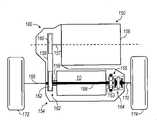
图2是根据本发明原理的包含图1A和图1B中变速器的齿轮布置的前轮驱动式变速驱动桥布置的示意图。2 is a schematic illustration of a front wheel drive transaxle arrangement incorporating the gear arrangement of the transmission of FIGS. 1A and 1B in accordance with the principles of the present invention.
具体实施方式Detailed ways
以下描述在本质上仅是示例性的,并不意图限定本公开、应用场合或用途。The following description is merely exemplary in nature and is not intended to limit the disclosure, application, or uses.
现在参看图1A,标号10总体地表示前轮驱动式多速变速器或八速变速器的一个实施例。所示变速器10为前轮驱动变速器或横向变速器,但可采用各种其它类型的变速器配置。变速器10包括变速器壳12、输入轴或输入部件14、输出轴或输出部件16以及齿轮布置18。输入部件14持续地连接在发动机(未示出)上,或连接在扭矩变换器的涡轮(未示出)上。输出部件16持续地与主减速器单元(未示出)或分动箱(未示出)相连。Referring now to FIG. 1A, the
变速器10的齿轮布置18包括第一行星齿轮组20、第二行星齿轮组22、第三行星齿轮组24和第四行星齿轮组26。行星齿轮组20,22,24和26连接在输入部件14和输出部件16之间。The
在本发明的一个优选实施例中,行星齿轮组20包括环形齿轮部件20A、行星齿轮架部件20B和太阳齿轮部件20C,行星齿轮架部件20B可旋转地支撑一组行星齿轮或小齿轮20D(图中仅显示了其中的一个)。环形齿轮部件20A与第一轴或第一中间部件42及第二轴或第二中间部件44相连接,以便共同旋转。行星齿轮架部件20B与输入轴或输入部件14及第三轴或第三中间部件46相连接,以便共同旋转。太阳齿轮部件20C与第四轴或第四中间部件48相连接,以便共同旋转。小齿轮20D构造成与太阳齿轮部件20C及环形齿轮部件20A相互啮合。In a preferred embodiment of the present invention,
行星齿轮组22包括环形齿轮部件22A、行星齿轮架部件22B和太阳齿轮部件22C,行星齿轮架部件22B可旋转地支撑一组行星齿轮或小齿轮22D。环形齿轮部件22A与第五轴或第五中间部件50相连接,以便共同旋转。行星齿轮架部件22B与输出轴或输出部件16相连接,以便共同旋转。太阳齿轮部件22C与第二轴或第二中间部件44相连接,以便共同旋转。小齿轮22D各构造成与太阳齿轮部件22C及环形齿轮部件22A相互啮合。Planetary gear set 22 includes a
行星齿轮组24包括环形齿轮部件24A、行星齿轮架部件24B和太阳齿轮部件24C,行星齿轮架部件24B可旋转地支撑一组行星齿轮或小齿轮22D。环形齿轮部件24A与第六轴或第六中间部件52相连接,以便共同旋转。行星齿轮架部件24B与输出轴或输出部件16相连接,以便共同旋转。太阳齿轮部件24C与第七轴或第七中间部件54相连接,以便共同旋转。小齿轮24D各构造成与太阳齿轮部件24C及环形齿轮部件24A相互啮合。Planetary gear set 24 includes a
行星齿轮组26包括环形齿轮部件26A、齿轮架部件26B和太阳齿轮部件26C,行星齿轮架部件26B可旋转地支撑一组行星齿轮或小齿轮26D。环形齿轮部件26A与第八轴或第八中间部件56相连接,以便共同旋转。行星齿轮架部件26B与第六轴或第六中间部件52相连接,以便共同旋转。太阳齿轮部件26C与第四轴或第四中间部件48相连接,以便共同旋转。小齿轮26D各构造成与太阳齿轮部件26C及环形齿轮部件26A相互啮合。Planetary gear set 26 includes a
变速器10还包括多个扭矩传递机构或扭矩传递装置,其包括第一离合器66、第二离合器68、第三离合器70、第一制动器72和第二制动器74。第一离合器66可选择性地接合,以便将第一轴或第一中间部件42连接到第七轴或第七中间部件54上。第二离合器68可选择性地接合,以便将第三轴或第三中间部件46连接到第七轴或第七中间部件54上。第三离合器70可选择性地接合,以便将第五部件或第五中间部件50连接到第七轴或第七中间部件54上。第一制动器72可选择性地接合,以便将第四轴或第四中间部件48连接到变速器壳12上,从而限制部件48相对于变速器壳12的旋转。最后,第二制动器74可选择性地接合,以便将第八轴或第八中间部件56连接到变速器壳12上,从而限制部件56相对于变速器壳12的旋转。The
变速器10能够以至少八个前进扭矩比和一个倒档扭矩比将扭矩从输入轴或输入部件14传递至输出轴或输出部件16。通过其中一个或多个扭矩传递机构(即第一离合器66、第二离合器68、第三离合器70、第一制动器72和第二制动器74)的接合而获得各个前进扭矩比和倒档扭矩比。本领域中的技术人员将容易地懂得,不同的速度比与各扭矩比相关联。因而,变速器10可获得八个前进速度比。The
变速器壳12包括第一壁或第一结构部件102、第二壁或第二结构部件104和第三壁或第三结构部件106。第三壁106将第一壁102和第二壁104互连起来,以限定空间或空腔110。输入轴或输入部件14通过轴承112而被第一壁102所支撑。输出轴或输出部件16通过轴承114而被第二壁104所支撑。行星齿轮组20,22,24和26以及扭矩传递机构66,68,70,72和74设置在空腔110中。此外,空腔110具有多个区域或区A、B、C、D、E和F,根据本发明的优选实施例,多个扭矩传递机构66,68,70,72和74将被特定地定位或安装在这些区域中。The
如图1A中所示,区A由这样的区域或空间来限定,其由第一壁102、行星齿轮组20、径向内侧由基准线“L”、且径向外侧由基准线“M”来界定边界,基准线“L”是沿轴向与输入轴14对准的纵向线,基准线“M”是毗邻行星齿轮组20,22,24和26的外径或外周边而延伸的纵向线。虽然基准线″M″在全部这几张图中显示为直线,但是应该懂得,基准线″M″是沿着行星齿轮组20,22,24和26的外周边的,并因此可以是阶梯状的或非线性的,这取决于各行星齿轮组20,22,24和26的外周边的位置。区B由这样的区域来限定,该区域由行星齿轮组20、行星齿轮组22、径向外侧由基准线“M”、且径向内侧由基准线“L”来界定边界。区C由这样的区域来限定,该区域由行星齿轮组22、行星齿轮组26、径向外侧由基准线“M”、且径向内侧由基准线“L”来界定边界。区D由这样的区域来限定,该区域由行星齿轮组26、行星齿轮组24、径向外侧由基准线“M”、且径向内侧由基准线“L”来界定边界。区E由这样的区域来限定,该区域由行星齿轮组24、第二端壁104、径向外侧由基准线“M”、且径向内侧由基准线“L”来界定边界。区F由这样的区域来限定,该区域由第一壁102、第二壁104、径向内侧由基准线“M”、且径向外侧由第三壁106来界定边界。As shown in FIG. 1A, zone A is defined by the region or space defined by the
在图1A所示的变速器10的齿轮布置18中,行星齿轮组20设置为最靠近第一壁102,行星齿轮组24设置为最靠近第二壁104,行星齿轮组22设置为相邻于行星齿轮组20,并且行星齿轮组26设置在行星齿轮组22和24之间。扭矩传递机构有意地定位在特定的区中,以便在变速器总尺寸、封装效率以及降低制造复杂度方面提供优势。在图1A所示的特定的示例中,第一离合器66和第二离合器68设置在区A中,第三离合器70设置在区C中,并且第一制动器72和第二制动器74设置在区F中。In the
然而,本发明可设想将扭矩传递机构66,68,70,72和74设置在其它区中的其它实施例。在图1B显示的图表中说明了扭矩传递机构66,68,70,72和74在这些区中的可行位置。图1B的图表在最左边列中列出了离合器和制动器,并在顶行列出了可用的定位离合器/制动器的区。图表中的“X”表示本发明设想将离合器或制动器定位在顶行中所列出的区中。例如,第一制动器72可定位在区A,C,E或F中,第二制动器74可定位在区A,D,E或F中。However, other embodiments in which the torque-transmitting
现在参看图2,其显示了根据本发明实施例的包含变速驱动桥154的前轮驱动动力系150。变速驱动桥154包括具有图1A和1B中的齿轮布置18的变速器10。变速驱动桥154安装在发动机156上。发动机156在发动机输出轴157中产生驱动扭矩,其驱动变速器10的输入轴14。发动机156通常是内燃机,然而,本发明可设想其它类型的发动机,如电动发动机和混合动力发动机。此外,变速驱动桥154包括传动链或传动带158、驱动链轮或齿轮160、从动链轮或齿轮162、差速器164、主减速器行星齿轮组166和分别驱动一对车轮172和174的一对驱动轴168和170。Referring now to FIG. 2 , a front
传动链或传动带158在第一端180与驱动链轮或齿轮160相接合,并且在第二端182与从动链轮或齿轮162相接合,驱动链轮或齿轮160联接在发动机输出轴或输出部件157上。从动链轮162可旋转地固定在驱动轴或可旋转的部件159上。驱动轴或可旋转的部件159联接在变速器10的输入轴14上。变速器10的输出轴16连接在输出套轴163上。输出套轴163联接在主减速器行星齿轮组166的太阳齿轮上,以实现所需的齿轮比。主减速器行星齿轮组166的齿轮架部件支撑多个小齿轮,这些小齿轮与主减速器行星齿轮组166的太阳齿轮及环形齿轮相啮合。主减速器行星齿轮组166的齿轮架部件可旋转地联接在差速器164的壳上,并将驱动扭矩传递给差速器164的壳。差速器164通过两组旋转地支撑在差速器壳中的伞齿轮而将发动机156所产生的驱动扭矩传送给两个驱动轴168和170。驱动轴168和170可旋转地固定在差速器164的伞齿轮上并可独立地被伞齿轮驱动,从而将驱动扭矩供给车辆车轮172和174。Drive chain or
本发明的说明书在本质上仅仅是示例性的,不脱离本发明要点的变型将属于本发明的范围内。这样的变型将不被视为脱离了本发明的精神和范围。The description of the invention is merely exemplary in nature and variations that do not depart from the gist of the invention are intended to be within the scope of the invention. Such modifications are not to be regarded as a departure from the spirit and scope of the invention.
Claims (24)
Applications Claiming Priority (4)
| Application Number | Priority Date | Filing Date | Title |
|---|---|---|---|
| US3010108P | 2008-02-20 | 2008-02-20 | |
| US61/030101 | 2008-02-20 | ||
| US12/269580 | 2008-11-12 | ||
| US12/269,580US8118700B2 (en) | 2008-02-20 | 2008-11-12 | Multi-speed transmission for a front wheel drive vehicle |
Publications (2)
| Publication Number | Publication Date |
|---|---|
| CN101513838Atrue CN101513838A (en) | 2009-08-26 |
| CN101513838B CN101513838B (en) | 2012-05-23 |
Family
ID=40955659
Family Applications (1)
| Application Number | Title | Priority Date | Filing Date |
|---|---|---|---|
| CN2009101179361AExpired - Fee RelatedCN101513838B (en) | 2008-02-20 | 2009-02-19 | Multi-speed transaxle for a front wheel drive vehicle |
Country Status (2)
| Country | Link |
|---|---|
| US (1) | US8118700B2 (en) |
| CN (1) | CN101513838B (en) |
Families Citing this family (12)
| Publication number | Priority date | Publication date | Assignee | Title |
|---|---|---|---|---|
| US8197378B2 (en)* | 2008-02-20 | 2012-06-12 | GM Global Technology Operations LLC | Multi-speed transaxle for a front wheel drive vehicle |
| US8157696B2 (en)* | 2008-02-21 | 2012-04-17 | GM Global Technology Operations LLC | Multi-speed transaxle for a front wheel drive vehicle |
| US8187138B2 (en)* | 2008-02-21 | 2012-05-29 | GM Global Technology Operations LLC | Multi-speed transaxle for a front wheel drive vehicle |
| US8267832B2 (en)* | 2008-04-16 | 2012-09-18 | GM Global Technology Operations LLC | Multi-speed transaxle |
| US8177676B2 (en)* | 2008-04-16 | 2012-05-15 | GM Global Technology Operations LLC | Multi-speed transaxle |
| US8167767B2 (en)* | 2008-04-18 | 2012-05-01 | GM Global Technology Operations LLC | Multi-speed transaxle |
| US8192320B2 (en)* | 2008-04-18 | 2012-06-05 | GM Global Technology Operations LLC | Multi-speed transaxle |
| US8241167B2 (en)* | 2008-04-21 | 2012-08-14 | GM Global Technology Operations LLC | Multi-speed transaxle |
| US8047952B2 (en) | 2008-04-21 | 2011-11-01 | GM Global Technology Operations LLC | Multi-speed transaxle |
| CN103410944B (en)* | 2013-08-29 | 2014-05-07 | 湖南农业大学 | An integrated transaxle |
| JP6036642B2 (en)* | 2013-10-28 | 2016-11-30 | マツダ株式会社 | Automatic transmission |
| US9625007B2 (en)* | 2014-08-12 | 2017-04-18 | Allison Transmission, Inc. | Multi-speed transmission |
Family Cites Families (27)
| Publication number | Priority date | Publication date | Assignee | Title |
|---|---|---|---|---|
| KR100305478B1 (en)* | 1997-10-08 | 2001-12-28 | 이계안 | Power train for 5-speed automatic transmission |
| US6176803B1 (en)* | 1999-09-28 | 2001-01-23 | Caterpillar Inc. | Transmission assembly with four planetary gear sets providing nine forward and one reverse gear ratio |
| JP4438247B2 (en)* | 2001-03-29 | 2010-03-24 | アイシン・エィ・ダブリュ株式会社 | Automatic transmission for vehicles |
| DE10115983A1 (en)* | 2001-03-30 | 2002-10-10 | Zahnradfabrik Friedrichshafen | Multi-speed transmission |
| DE10115985A1 (en)* | 2001-03-30 | 2002-10-10 | Zahnradfabrik Friedrichshafen | Multi-speed transmission |
| JP4453297B2 (en)* | 2003-05-27 | 2010-04-21 | トヨタ自動車株式会社 | Planetary gear type multi-stage transmission for vehicles |
| JP4380291B2 (en)* | 2003-10-27 | 2009-12-09 | トヨタ自動車株式会社 | Planetary gear type multi-stage transmission for vehicles |
| US7011597B2 (en)* | 2004-03-24 | 2006-03-14 | General Motors Corporation | Multi-speed transmission |
| DE102004040904B4 (en)* | 2004-08-24 | 2015-11-26 | Zf Friedrichshafen Ag | Multi-speed transmission |
| US7163484B2 (en)* | 2005-01-24 | 2007-01-16 | General Motors Corporation | Eight-speed transmissions with four planetary gear sets |
| US7204780B2 (en)* | 2005-05-25 | 2007-04-17 | General Motors Corporation | Multi speed transmission |
| US7341537B2 (en)* | 2005-05-25 | 2008-03-11 | General Motors Corporation | Multi-speed transmission |
| DE102005032880B4 (en)* | 2005-07-14 | 2016-07-28 | Zf Friedrichshafen Ag | Multi-speed transmission |
| US7775931B2 (en)* | 2007-03-16 | 2010-08-17 | Gm Global Technology Operations, Inc. | Multi-speed transmission |
| US8123650B2 (en)* | 2008-02-20 | 2012-02-28 | GM Global Technology Operations LLC | Multi-speed transaxle for a front wheel drive vehicle |
| US8197378B2 (en)* | 2008-02-20 | 2012-06-12 | GM Global Technology Operations LLC | Multi-speed transaxle for a front wheel drive vehicle |
| US8123652B2 (en)* | 2008-02-20 | 2012-02-28 | GM Global Technology Operations LLC | Multi-speed transaxle for a front wheel drive vehicle |
| US8123651B2 (en)* | 2008-02-20 | 2012-02-28 | GM Global Technology Operations LLC | Multi-speed transaxle for a front wheel drive vehicle |
| US8187138B2 (en)* | 2008-02-21 | 2012-05-29 | GM Global Technology Operations LLC | Multi-speed transaxle for a front wheel drive vehicle |
| US8157696B2 (en)* | 2008-02-21 | 2012-04-17 | GM Global Technology Operations LLC | Multi-speed transaxle for a front wheel drive vehicle |
| US8177676B2 (en)* | 2008-04-16 | 2012-05-15 | GM Global Technology Operations LLC | Multi-speed transaxle |
| US8267832B2 (en)* | 2008-04-16 | 2012-09-18 | GM Global Technology Operations LLC | Multi-speed transaxle |
| US7998015B2 (en)* | 2008-04-17 | 2011-08-16 | GM Global Technology Operations LLC | Multi-speed transaxle for a front wheel drive vehicle |
| US8167767B2 (en)* | 2008-04-18 | 2012-05-01 | GM Global Technology Operations LLC | Multi-speed transaxle |
| US8192320B2 (en)* | 2008-04-18 | 2012-06-05 | GM Global Technology Operations LLC | Multi-speed transaxle |
| US8047952B2 (en)* | 2008-04-21 | 2011-11-01 | GM Global Technology Operations LLC | Multi-speed transaxle |
| US8241167B2 (en)* | 2008-04-21 | 2012-08-14 | GM Global Technology Operations LLC | Multi-speed transaxle |
- 2008
- 2008-11-12USUS12/269,580patent/US8118700B2/ennot_activeExpired - Fee Related
- 2009
- 2009-02-19CNCN2009101179361Apatent/CN101513838B/ennot_activeExpired - Fee Related
Also Published As
| Publication number | Publication date |
|---|---|
| CN101513838B (en) | 2012-05-23 |
| US20090209384A1 (en) | 2009-08-20 |
| US8118700B2 (en) | 2012-02-21 |
Similar Documents
| Publication | Publication Date | Title |
|---|---|---|
| CN101513838B (en) | Multi-speed transaxle for a front wheel drive vehicle | |
| CN101513837B (en) | Multi-speed transaxle for a front wheel drive vehicle | |
| CN101513833B (en) | Multi-speed transaxle for a front wheel drive vehicle | |
| US8202194B2 (en) | Clutch and gear arrangement for a front wheel drive vehicle | |
| US8197378B2 (en) | Multi-speed transaxle for a front wheel drive vehicle | |
| US7998015B2 (en) | Multi-speed transaxle for a front wheel drive vehicle | |
| US8123651B2 (en) | Multi-speed transaxle for a front wheel drive vehicle | |
| US8267832B2 (en) | Multi-speed transaxle | |
| US8187138B2 (en) | Multi-speed transaxle for a front wheel drive vehicle | |
| US8167767B2 (en) | Multi-speed transaxle | |
| US8047952B2 (en) | Multi-speed transaxle | |
| US8192320B2 (en) | Multi-speed transaxle | |
| US8157696B2 (en) | Multi-speed transaxle for a front wheel drive vehicle | |
| US8241167B2 (en) | Multi-speed transaxle | |
| US8496557B2 (en) | Clutch and gear arrangement for a front wheel drive vehicle | |
| US8177676B2 (en) | Multi-speed transaxle | |
| US8025605B2 (en) | Multi-speed transmission for a front wheel drive vehicle |
Legal Events
| Date | Code | Title | Description |
|---|---|---|---|
| C06 | Publication | ||
| PB01 | Publication | ||
| C10 | Entry into substantive examination | ||
| SE01 | Entry into force of request for substantive examination | ||
| C14 | Grant of patent or utility model | ||
| GR01 | Patent grant | ||
| CF01 | Termination of patent right due to non-payment of annual fee | Granted publication date:20120523 | |
| CF01 | Termination of patent right due to non-payment of annual fee |