CN101512434B - Portable Image Acquisition and Camera Device - Google Patents
Portable Image Acquisition and Camera DeviceDownload PDFInfo
- Publication number
- CN101512434B CN101512434BCN2007800333239ACN200780033323ACN101512434BCN 101512434 BCN101512434 BCN 101512434BCN 2007800333239 ACN2007800333239 ACN 2007800333239ACN 200780033323 ACN200780033323 ACN 200780033323ACN 101512434 BCN101512434 BCN 101512434B
- Authority
- CN
- China
- Prior art keywords
- upper panel
- image acquisition
- acquisition module
- microprocessor
- image
- Prior art date
- Legal status (The legal status is an assumption and is not a legal conclusion. Google has not performed a legal analysis and makes no representation as to the accuracy of the status listed.)
- Active
Links
Images

Classifications
- H—ELECTRICITY
- H04—ELECTRIC COMMUNICATION TECHNIQUE
- H04N—PICTORIAL COMMUNICATION, e.g. TELEVISION
- H04N1/00—Scanning, transmission or reproduction of documents or the like, e.g. facsimile transmission; Details thereof
- H04N1/00519—Constructional details not otherwise provided for, e.g. housings, covers
- H04N1/00525—Providing a more compact apparatus, e.g. sheet discharge tray in cover
- H04N1/00535—Providing a more compact apparatus, e.g. sheet discharge tray in cover using rotatably mounted or foldable components
- H—ELECTRICITY
- H04—ELECTRIC COMMUNICATION TECHNIQUE
- H04N—PICTORIAL COMMUNICATION, e.g. TELEVISION
- H04N1/00—Scanning, transmission or reproduction of documents or the like, e.g. facsimile transmission; Details thereof
- H04N1/04—Scanning arrangements, i.e. arrangements for the displacement of active reading or reproducing elements relative to the original or reproducing medium, or vice versa
- H04N1/19—Scanning arrangements, i.e. arrangements for the displacement of active reading or reproducing elements relative to the original or reproducing medium, or vice versa using multi-element arrays
- H04N1/195—Scanning arrangements, i.e. arrangements for the displacement of active reading or reproducing elements relative to the original or reproducing medium, or vice versa using multi-element arrays the array comprising a two-dimensional array or a combination of two-dimensional arrays
- H04N1/19594—Scanning arrangements, i.e. arrangements for the displacement of active reading or reproducing elements relative to the original or reproducing medium, or vice versa using multi-element arrays the array comprising a two-dimensional array or a combination of two-dimensional arrays using a television camera or a still video camera
- H—ELECTRICITY
- H04—ELECTRIC COMMUNICATION TECHNIQUE
- H04N—PICTORIAL COMMUNICATION, e.g. TELEVISION
- H04N23/00—Cameras or camera modules comprising electronic image sensors; Control thereof
- H04N23/50—Constructional details
- H—ELECTRICITY
- H04—ELECTRIC COMMUNICATION TECHNIQUE
- H04N—PICTORIAL COMMUNICATION, e.g. TELEVISION
- H04N2201/00—Indexing scheme relating to scanning, transmission or reproduction of documents or the like, and to details thereof
- H04N2201/0077—Types of the still picture apparatus
- H04N2201/0081—Image reader
- H—ELECTRICITY
- H04—ELECTRIC COMMUNICATION TECHNIQUE
- H04N—PICTORIAL COMMUNICATION, e.g. TELEVISION
- H04N2201/00—Indexing scheme relating to scanning, transmission or reproduction of documents or the like, and to details thereof
- H04N2201/0096—Portable devices
- H—ELECTRICITY
- H04—ELECTRIC COMMUNICATION TECHNIQUE
- H04N—PICTORIAL COMMUNICATION, e.g. TELEVISION
- H04N2201/00—Indexing scheme relating to scanning, transmission or reproduction of documents or the like, and to details thereof
- H04N2201/04—Scanning arrangements
- H04N2201/0402—Arrangements not specific to a particular one of the scanning methods covered by groups H04N1/04 - H04N1/207
- H04N2201/0436—Scanning a picture-bearing surface lying face up on a support
Landscapes
- Engineering & Computer Science (AREA)
- Multimedia (AREA)
- Signal Processing (AREA)
- Studio Devices (AREA)
- Accessories Of Cameras (AREA)
Abstract
Description
Translated fromChinese技术领域technical field
本发明是关于一种便携式图像采集及摄像装置,更详细地说,本发明是关于一种具有图像采集模块设置于其上的便携式图像采集及摄像装置。The present invention relates to a portable image capture and camera device, more specifically, the present invention relates to a portable image capture and camera device with an image capture module disposed thereon.
背景技术Background technique
图像采集装置如扫描仪等,分析并将图像或物体转换成数字图像。举例来说,基本的图像扫描仪将相片、印刷文字或手写文字分析、处理及转换为数字图像。存在多年的台式图像扫描仪是最普遍的图像采集装置。Image acquisition devices, such as scanners, analyze and convert images or objects into digital images. For example, a basic image scanner analyzes, processes and converts photographs, printed or handwritten text into digital images. Desktop image scanners, which have been around for many years, are the most common image capture devices.
近来,体积较小、便携式版本的台式扫描仪已在市场上销售,主要是针对扫描商务或其它类型名片。此种现有技术的名片扫描仪的例子包括位于MassachusettsCambridge的CardScan公司所销售的名片读取机。另一现存名片读取机的型号为BizCard Reader 900c,此机型由位于California Sunnyvale经营电子文件技术的CardReader公司所销售。Recently, smaller, portable versions of desktop scanners have been marketed, primarily for scanning business or other types of business cards. Examples of such prior art business card scanners include the business card reader sold by CardScan, Inc. of Cambridge, Massachusetts. Another existing business card reader is the BizCard Reader 900c, sold by CardReader Inc., Sunnyvale, California, which operates electronic document technology.
有些扫描仪,包括台式扫描仪,使用玻璃平板设计及扫描头来采集扫描图像。此扫描头包括成像元件、数面镜子及滤光片和透镜。此扫描头和其它扫描仪组件共同运行,如玻璃板、灯、步进电动机、稳定杆、皮带及电源供应器。台式扫描仪通常需要使扫描主体或物体朝下放置于玻璃板上。连接到步进电动机的皮带移动扫描头横越文件,使成像元件及光源也横越玻璃板读取整个区域。此装配是连接到一稳定杆以确保在扫描主体的整个扫描中不会有偏差。由于所述主体所反射的光,使得此主体对成像元件来说是可见的。Some scanners, including desktop scanners, use a glass flatbed design with a scanning head to capture scanned images. The scan head consists of an imaging element, several mirrors and filters and lenses. The scan head works with other scanner components such as the glass plate, lights, stepper motors, stabilizer bars, belts, and power supply. Desktop scanners typically require the subject or object to be scanned to be placed face down on a glass plate. A belt connected to a stepper motor moves the scan head across the document, causing the imaging element and light source to also read the entire area across the glass plate. This assembly is connected to a stabilizer bar to ensure that there is no deviation throughout the scan of the scanned subject. The subject is visible to the imaging element due to the light reflected by the subject.
有些扫描仪,例如前述现有技术装置及其它类似的便携式图像扫描装置,是配备了自动文件馈送特征。使用者将扫描主体放置在入口槽,此主体即可自动地被送入扫描仪中。在自动文件馈送扫描过程中,当此主体利用滚轴以一定速度移动经过扫描仪时,成像元件维持静止不动。扫描之后,主体可从独立的出口槽(图未示出)取出。Some scanners, such as the aforementioned prior art devices and other similar portable image scanning devices, are equipped with automatic document feeding features. The user places the scanning subject in the inlet slot, and the subject can be automatically fed into the scanner. During automatic document-feed scanning, the imaging element remains stationary while the subject is moved at a speed across the scanner using rollers. After scanning, the subject can be removed from a separate exit chute (not shown).
这种现有技术装置,典型地利用某种机载的图像及文字采集软件技术或其它软件应用程序,来读取和扫描名片上的所有信息,并转换成数字图像。一种此类应用程序是光学字符识别(optical character recognition,OCR),其用以自扫描主体扫描文字及其它图像,并且转换成计算机中的文字。OCR通常利用平均程序来决定文字的形状,并将其对应到正确的字母或数字。因此,当扫描名片时,名片上打字和手写的信息都自动地被读进数据库。名片的扫描图像亦可储存成计算机可读取的文件,以供进一步的变更或图像增强。Such prior art devices typically utilize some kind of on-board image and text capture software technology or other software application to read and scan all the information on the business card and convert it into a digital image. One such application is optical character recognition (OCR), which is used to scan text and other images from a scanning subject and convert them into text on a computer. OCR usually uses an averaging process to determine the shape of the text and map it to the correct letter or number. Therefore, when the business card is scanned, the typed and handwritten information on the business card is automatically read into the database. Scanned images of business cards can also be saved as computer-readable files for further alteration or image enhancement.
无论是台式或便携式图像扫描仪,成像元件是图像采集装置的关键元件之一,而且结果的图像品质是取决于该装置的成像元件。电荷耦合器件(charge-coupleddevice,CCD)芯片是最常见的成像技术。CCD技术一体化了称为感光单元(photosites)的光敏二极管集合,其将光子转换为电荷。每个感光单元对光线敏感,使得当亮光打到单一感光单元时,电荷便聚集在该感光单元。扫描图像通过镜面阵列、滤光片和透镜而到达CCD,而这些元件的确切设定是取决于扫描仪的模型。一般来说,文件的图像是被一有角度的镜子反射到另一镜子,每个镜子均具有轻微的弯曲,以将被反射的图像聚焦到另一镜子的表面上。最后一个镜子将图像反射到一透镜,该透镜将图像聚焦到成像元件。与移动的扫描头、皮带和电机有关的CCD装置的镜子数目,使得CCD通常体积庞大,因而限制了装置的整体尺寸。Whether it is a desktop or a portable image scanner, the imaging component is one of the key components of the image capture device, and the resulting image quality is dependent on the imaging component of the device. Charge-coupled device (charge-coupled device, CCD) chip is the most common imaging technology. CCD technology incorporates collections of photosensitive diodes called photosites, which convert photons into electrical charges. Each photosensitive unit is sensitive to light, so that when bright light hits a single photosensitive unit, charges accumulate on that photosensitive unit. The scanned image passes through a mirror array, filters, and lenses to the CCD, and the exact settings of these elements depend on the model of scanner. Typically, an image of a document is reflected from one angled mirror to another, each mirror having a slight curvature to focus the reflected image onto the surface of the other mirror. The last mirror reflects the image to a lens that focuses the image onto the imaging element. The number of mirrors in a CCD device associated with moving scan heads, belts and motors makes the CCD usually bulky, thus limiting the overall size of the device.
被一体化到当今图像采集装置的第二类型成像元件是接触式图像传感器(contact image sensor,CIS)技术。CIS技术通常被一体化到平板式扫描仪中,以作为CCD技术的替代选择。CIS技术在玻璃板下使用发光二极管阵列。CIS以多列红色、绿色及蓝色发光二极管(light emitting diode,LED)取代了CCD镜面阵列、滤光片及透镜。此成像元件一般包括三百到六百个跨越扫描区域的幅宽的传感器,并且非常靠近放置文件的玻璃板。扫描图像时,该等LED结合起来以提供白光来照亮图像,接着此图像由一列传感器所采集。CIS技术的扫描装置一般而言体积较小,但此种装置无法提供与采用CCD技术的扫描装置相同的分辨率或整体图像品质。The second type of imaging element being integrated into today's image capture devices is contact image sensor (CIS) technology. CIS technology is often integrated into flatbed scanners as an alternative to CCD technology. CIS technology uses an array of light-emitting diodes under a glass plate. CIS replaces the CCD mirror array, filter and lens with multiple rows of red, green and blue light emitting diodes (light emitting diodes, LEDs). This imaging element typically consists of three hundred to six hundred sensors that span the swath of the scan area and are placed in close proximity to the glass plate on which the document is placed. When an image is scanned, the LEDs combine to provide white light to illuminate the image, which is then captured by an array of sensors. Scanning devices using CIS technology are generally smaller in size, but such devices do not provide the same resolution or overall image quality as scanning devices using CCD technology.
无论图像采集装置所使用的技术类型为何,现存便携式扫描仪的玻璃平板设计在装置上仍然需要构建入口槽。因此,即使图像采集装置使用更紧致的CIS技术,此装置的整体厚度仍然相当的大。Regardless of the type of technology used by the image capture device, the glass flat panel design of existing portable scanners still requires an entry slot to be built into the device. Therefore, even if the image acquisition device uses more compact CIS technology, the overall thickness of the device is still quite large.
其它当今的扫描装置,如台湾蒙恬科技(PennPower Technology Ltd.)销售的WorldCard duet,包括了网络摄像机来扫描和读取名片的图像。此种装置使用图像及文字识别软件来识别名片上印制的信息。然而,因为WorldCard duet装置必须设定为网络摄像机来采集名片的图像,所以欠缺便携性和多样性。因此,用尸只能便用WorldCard duet连接个人计算机或其它类似装置。Other current scanning devices, such as the WorldCard duet sold by Taiwan's PennPower Technology Ltd., include web cameras to scan and read images of business cards. This device uses image and text recognition software to recognize information printed on business cards. However, since the WorldCard duet device must be configured as a webcam to capture images of business cards, it lacks portability and versatility. Therefore, users can only use the WorldCard duet to connect to a personal computer or other similar devices.
一便携式图像采集装置较佳地是体积精巧的,而且最好只有口袋大小。图像采集装置可以在尺寸上与标准大小的信用卡或名片类似,但需要稍厚的宽度。图像采集装置应该最好可以采集印制在名片以及其它类似物体上的数据,如文字或其它图像等,以供进一步存储和使用。此装置也可能包括适当软件,以将采集的文字和图像转换成可读取的文件,以供进一步的组织和分类。此装置最好也可以具备数码相机功能,以采集除了名片之外的其它图像主体。此装置也可以借助任何可能的数据传输方式,以具有和其它外部装置通信的能力,使得装置之间的数据输传送更加便利。A portable image capture device is preferably compact and preferably pocket-sized. The image capture device can be similar in size to a standard-sized credit card or business card, but requires a slightly thicker width. The image capture device should preferably be able to capture data printed on business cards and other similar objects, such as text or other images, for further storage and use. The device may also include appropriate software to convert captured text and images into readable files for further organization and classification. Preferably, the device can also function as a digital camera to capture image subjects other than business cards. This device can also have the ability to communicate with other external devices by means of any possible data transmission method, so that the data transmission between devices is more convenient.
发明内容Contents of the invention
本发明提供一种便携式图像采集及摄像装置,包括装置本体及上面板,所述上面板可移置地啮合于所述本体,且具有图像采集模块设置在其上。下面板亦可移置地啮合于所述本体,用以当所述下面板展开到开启位置时,接收并支撑第一物体。所述上面板是可移动的,以自收藏位置展开到第一展开位置,以成像位于所述下面板的主体(名片读取模式),及展开到第二展开位置,以成像远离所述装置设置的物体(摄像模式)。The invention provides a portable image acquisition and camera device, which includes a device body and an upper panel, the upper panel is displaceably engaged with the body, and has an image acquisition module disposed thereon. The lower panel is also displaceably engaged with the body for receiving and supporting the first object when the lower panel is unfolded to the open position. The upper panel is movable to deploy from a stowed position to a first deployed position for imaging subjects located on the lower panel (business card reading mode), and to a second deployed position for imaging away from the device Set object (camera mode).
所述装置包括图像采集模块,位于所述上面板的表面。此面板可旋转90度,以使用此图像采集模块作为名片读取机。此面板可进一步地被旋转,如一额外90度,以使用此图像采集模块作为一数码相机。此装置使用成像元件采集一图像,并且建立一信息的数字图像。所揭露的装置除了存储器组件外,具有内置的文字及字符识别软件,使得采集的信息在必要时可转换成可读取的计算机文件,并且被存储以供作其后的转换。任何使用所揭露装置所采集的图像可使用最适当的数据传输方法,和外部装置进行传输。The device includes an image acquisition module located on the surface of the upper panel. This panel can be rotated 90 degrees to use this image capture module as a business card reader. The panel can be further rotated, such as an additional 90 degrees, to use the image capture module as a digital camera. The device captures an image using imaging elements and creates a digital image of information. In addition to the memory component, the disclosed device has built-in text and character recognition software, so that the collected information can be converted into a readable computer file when necessary, and stored for subsequent conversion. Any image captured using the disclosed device can be transferred to an external device using the most appropriate data transfer method.
一种如前段所揭露的便携式图像采集装置,可用来作为名片读取机和/或数码相机。此装置省却了在大多数便携式名片读取机中通常使用的玻璃板,因此体积精巧扁薄。此装置使用电子摄像技术以采集数据的图像及其它印制在名片上的图像。因此,此装置在不用作名片读取机时,可用来作为数码相机。A portable image acquisition device disclosed in the preceding paragraph can be used as a business card reader and/or a digital camera. This unit eliminates the glass plate typically found in most portable business card readers, resulting in a compact, low profile. This device uses electronic photography to capture images of data and other images printed on business cards. Therefore, the device can be used as a digital camera when it is not used as a business card reader.
在另一实施例中,上面板可以是可滑动地啮合于所述本体,并且移动到一位置以成像远离所述装置设置的物体,并进一步地旋转以成像位于下面板的图像主体。In another embodiment, the upper panel may be slidably engaged to the body, and moved to a position to image an object located away from the device, and further rotated to image an image subject located on the lower panel.
在目前较佳实施例中,第一展开位置是相对于所述收藏位置旋转90度角的位置,且第二展开位置是相对于所述收藏位置旋转约180度角的位置。In a presently preferred embodiment, the first deployed position is a position rotated by an angle of 90 degrees relative to the stowed position, and the second deployed position is a position rotated by an angle of approximately 180 degrees relative to the stowed position.
当上面板是被设置于收藏位置时,图像采集模块可以被形成在所述上面板的第一表面,如此所述图像采集模块与所述本体实质上呈邻接关系。When the upper panel is set at the stowed position, the image acquisition module may be formed on the first surface of the upper panel, so that the image acquisition module is substantially adjacent to the main body.
可提供位置传感器以产生输出信号,表示所述上面板相对于所述本体的方向或位置。A position sensor may be provided to generate an output signal indicative of the orientation or position of the upper panel relative to the body.
提供处理电路用以接收来自图像采集模块的信息,并且产生所述信息的输出显示。此处理电路可包括显示装置及微处理器,此微处理器与显示装置、图像采集模块及位置传感器进行电子通信。此微处理器可用以响应来自位置传感器的信号,修改自图像采集模块接收的信息的处理。因此,此微处理器可调整处理程序,例如调整与上面板的传感位置有关的光学字符识别软件的运行,上面板的传感位置表示该装置在名片读模式下。此处理电路亦可响应来自位置传感器的指示所述装置是运行在名片读取模式或摄像模式下的信息,调整图像的处理。因此,视场及焦距可相应所述上面板的传感位置(传感模式),或可支撑此图像采集模块的其它组件的传感位置而调整。Processing circuitry is provided to receive information from the image acquisition module and to generate an output display of the information. The processing circuitry may include a display device and a microprocessor in electronic communication with the display device, image acquisition module and position sensor. The microprocessor is operable to modify the processing of information received from the image acquisition module in response to signals from the position sensor. Therefore, the microprocessor can adjust the processing program, for example, adjust the operation of the optical character recognition software in relation to the sensing position of the upper panel, which indicates that the device is in the business card reading mode. The processing circuitry may also adjust image processing in response to information from the position sensor indicating whether the device is operating in a business card reading mode or a camera mode. Therefore, the field of view and focal length can be adjusted corresponding to the sensing position of the upper panel (sensing mode), or the sensing position of other components that can support the image acquisition module.
附图说明Description of drawings
结合以下说明及图式将可以更佳地理解此揭露的各实施例的特征及优点,其中全文相同的编号意指相同的组件,附图中:The features and advantages of the disclosed embodiments will be better understood with reference to the following description and drawings, wherein the same numbers throughout refer to the same components. In the drawings:
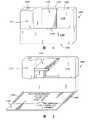
图1是根据本发明一实施例的位于关闭或收藏位置的图像采集装置的前视立体图;FIG. 1 is a front perspective view of an image capture device in a closed or stowed position according to an embodiment of the present invention;
图2是本发明一实施例的位于部分旋转位置以作为名片读取装置的图像采集装置的前视立体图;FIG. 2 is a front perspective view of an image capture device in a partially rotated position as a business card reading device according to an embodiment of the present invention;
图3是图2实施例的图像采集装置的侧视图;Fig. 3 is a side view of the image acquisition device of Fig. 2 embodiment;
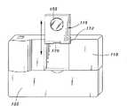
图4是本发明一实施例的位于完全旋转位置以作为相机的图像采集装置的前视立体图;FIG. 4 is a front perspective view of an image acquisition device in a fully rotated position serving as a camera according to an embodiment of the present invention;
图5是本发明另一实施例的位于完全旋转位置以作为数码相机的图像采集装置的前视立体图;FIG. 5 is a front perspective view of an image acquisition device in a fully rotated position as a digital camera according to another embodiment of the present invention;
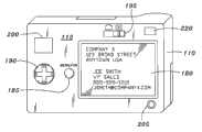
图6是根据本发明的图像采集装置的后视立体图;以及6 is a rear perspective view of an image capture device according to the present invention; and
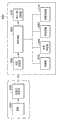
图7是根据本发明可用来运行图像采集装置的示范系统的方块图。7 is a block diagram of an exemplary system that may be used to operate an image capture device in accordance with the present invention.
具体实施方式Detailed ways
请参考图示,特别是图1,其表示一图像采集装置100位于关闭位置的前视立体图。装置100的形状实质上为方形。然而,装置100亦可以其它形状所构成。Please refer to the illustrations, especially FIG. 1 , which shows a front perspective view of an
装置100包括一具有较为平坦的一前表面111及一后表面的本体110,如图6所示。可绕轴旋转的上面板115是朝向前表面111的一顶端边缘120设置。可绕轴旋转的下面板125是朝向前表面的一底端边缘130设置。上面板115是借助位于或接近顶端边缘120的一枢轴170被支撑在前表面111,如此上面板115可自由地自本体110向外转动约180度,并返回原来位置。上面板115典型地是借助将上面板115以向上的方式自本体110往外旋转而被开启,且借助将上面板115以向下的方式旋转直到与本体110平靠而被关闭。The
在其它实施例中,上面板115可借助直接上推的方式而沿前表面111移动,使此装置可作为数码相机,细节如图5的说明。本体110可包含一凹槽以容纳上面板115,如此使上面板115于收回位置时与前表面111齐平。上面板115可使用传统安装硬件以被可滑动地装置在插槽中,因此使用者可施力以直接往上展开上面板115,直到其实质上自本体110移置开来。In other embodiments, the
下面板125借助位于或接近底端边缘130的一枢轴(图未示出)而支撑在前表面111上,如此下面板125可自本体110向外转动大约90度,并返回原来位置。因此,下面板125是可自本体110向外转动的,到实质上垂直于前表面111的平面的一方位。The
释放按钮135可位于下表面125上,用以展开下面板125,使其转动并自本体110水平地展开。另一选择为,如果省略了下面板125的释放按钮130,下面板125可以手动地被转动并且展开。装置100还包括一执行按钮160,是被压下以执行录制及存储主体的图像到主体110内部所内置的存储器或其它可移动式存储器存储模块的一程序,细节如关于图7的说明。执行按钮160较佳地是为位于上表面本体110上,但亦可以位于不干扰装置100运行的本体110的其它位置。A
图2为装置100在一开启位置(名片读取模式)的一前视立体图。上面板115及下面板125是自本体110的前表面111被旋转约90度。下面板125由一第一侧面边缘145及一第二侧面边缘150所界限。相对于下面板125,第一和第二侧面边缘145、150可被稍微提起以导引及使如名片的图像主体140在置入下面板125上时更方便。做为另一选择地,图像主体140可为使用者所选择采集图像的材料或物体。FIG. 2 is a front perspective view of the
图3是图2所示的装置100的侧视图,其中上面板115及下面板125是在相对于本体110约90度的一展开位置。图像主体140是设置在下面板125上面。上面板115包括一图像采集模块155,例如一CCD或CMOS摄像模块。然而,任何可用于采集图像本体140的图像的采集模块155的种类,均可依照在此所述的装置100的功能来使用。图像采集模块155是通过适当方式,譬如一薄且软性的电路连接器,而连接到处理电路200,如图7所绘示的连接方式。图像采集模块155可以在当上面板115相对于本体110部分或全部旋转时被启动,且在当上面板115部分或全部返回原来位置(收藏位置)时被停用。FIG. 3 is a side view of the
当上面板115是位于相对于本体110大约为90度的一旋转或展开位置时,图像采集模块155可具有一预先决定的焦深,使得图像主体的特征保留在景深162之内。当上面板115是相对于主体110旋转约90度时,图像采集模块155可还包括一预先决定的视场160,使得一典型大小的名片可保留在图像采集模块155的视场160之内。When the
上面板115还可被旋转到相对于本体110约180度的一位置,使装置100可以作为数码相机。如图4所示,上面板115可旋转约180度而到达一位置,于此位置装置100可作为数码相机。因此,上面板115连同图像采集模块155可部分展开,或者自它的收藏位置旋转约90度到达一部分展开的位置,于此部分展开的位置该装置100可作为名片读取机。当上面板115完全展开时,如旋转约180度,或者旋转到约90度至180度之间的一位置,装置100可作为数码相机。在应用程序相应特殊应用而建议一图像处理的修正的地方,可包括一位置传感器以读出下面板125的位置,并且据此调整处理。因此,举例来说,在此装置是以名片读取模式运行并且下面板125是从收藏位置展开约90度的地方,处理器可用以相应适合成像一名片或其它位于下面板125的图像主体的焦距及视场,而调整成像。然而,在位置传感器检测到上面板从收藏位置旋转180度,或从收藏位置旋转90度到180度之间的其它位置,处理器可用以成像较宽的视场或焦距。The
请参考图3及图4所示的一示范性的位置传感器172,其用以相应上面板115关于枢轴170的相对位置或方向而产生一信号。位置传感器172可以多种方式实施,且用以产生一表示上面板115相对于本体110的旋转的信号。在一实施例中,位置传感器172是用以产生信号,其指示上面板115已经到达一上面板115的预定相对位置,例如收藏位置、相对于本体110展开90度、或者相对于本体110展开180度。此枢轴170可被构建为当上面板115到达那些分立位置时,可释放地固定上面板115到该等位置。在另一实施例中,位置传感器172是用以产生连续的可变信号,表示上面板115关于本体110的相对展开位置,或者关于其它固定参考点。Please refer to an
图4所示为装置100的前视立体图,其显示上面板115旋转约180度,亦即完全展开。焦深及视场并未被固定,而且在当上面板115展开到此区域时可被相应调整。图像采集装置155可包括一缩放功能,其可使用一选单按钮(图未示出)控制,细节如关于图6的说明。FIG. 4 shows a front perspective view of the
在另一实施例中,如图5所示,上面板115可垂直移动到一摄像模式位置,且不需转动。如图5所示,此装置在名片读取模式下的使用,可以在上面板115展开到其向上位置后,借助绕枢轴170转动而起作用。In another embodiment, as shown in FIG. 5 , the
对于所属领域具备通常知识者来说,装置100可实作成各种不同的结构。用来展开上面板115的特殊机制、用来监测上面板115移动的传感机制,以及可用来相应上面板115的位置而实施的处理功能及因此欲操作的模式,各可依照其它技术及喜好而被选择及修改,而不脱离本发明的更广阔观点。For those skilled in the art, the
图6为类似传统数码相机的装置100的一其它实施例的一后视立体图。本体110的后表面112可包括一显示屏幕180,例如一液晶屏幕。显示屏幕180在图像采集过程中显示主体的一图像,让使用者于需要时可进行任何调整。显示屏幕180还可以显示采集图像,让使用者重新观看,如此使用者于需要时可重复操作。一存储器插槽210可用以容纳一可移动存储器存储模块。电源供应输入205可供以连接一交流电源供应器。选单按钮185可用以处理及控制与控制单元190有关的装置的功能或程序。图像搜寻器200可供使用者观看图像主体。使用者可在图像搜寻器200及显示屏幕180之间切换图像。模式选择器195可用以选择装置100的模式,例如使用装置100作为名片读取机或数码相机。如果上面板115自本体旋转移置时装置100未自动启动,则可包括电源按钮220。一合适的实体连接器可被插入数据传输装置输入215以使采集的影像传输到外部装置更方便。FIG. 6 is a rear perspective view of another embodiment of a conventional digital camera-
图7显示用以操作装置100的一系统的示范设定的方块图。装置100可具有一类似数码静态相机的电路设定。如前述说明,装置包括用以聚焦光线到图像采集模块255上的透镜250,以建立一图像主体的图像。图像采集模块255较佳地是一CCD摄像模块,其亦可为一CIS摄像模块,一CMOS摄像模块或其它任何图像采集模块。图像采集模块255与一模数(analog to digital,A/D)转换器260进行通信。A/D转换器260接收由图像采集模块255所输出的电荷,并且将这些电荷转换到此图像所表示的数字信号。A/D转换器与控制装置100(包括内置软件和其它固件)运行的微处理器265进行通信。存储器275可为内置存储器,或可分离连接到微处理器的一移动式快闪存储器模块。当图像采集模块255传输图像到微处理器265。微处理器265还可连接一位于主体后表面的显示装置285,如关于图6说明的LED显示屏幕,以对用户显示图像输出。此外,装置的其它组件输出,假设存在的情况,是提供到处理器265,包括电源按钮220、选单按钮185以及控制单元190。处理器265连接到可以是交流电源的电源供应器280。电源供应器280亦可为可充电式锂离子电池。FIG. 7 shows a block diagram of an exemplary setup of a system for operating the
采集图像的数据及信息可以一输入/输出装置270或其它连接的方式,自装置100上传或传输。在一实施例中,从装置100收集的图像及其它数据是通过实体连接方式,如一RS232或通用串行总线(Universal Serial Bus,USB)接口,传送到个人计算机。实体连接方式亦可通过使用一类似个人数字助理(personal digital assistant,PDA)(图未示)的托架来完成,此个人数字助理可以电性耦接到个人计算机以及可供装置100插入的地方。当装置放入托架时,信息传输可通过托架的一控制器启动或自动启动。数据亦可通过短距离无线传输方式,如蓝芽(Bluetooth),从装置100传送到个人计算机。The data and information of the collected images can be uploaded or transmitted from the
上述仅为本发明的例举,并非用来限制本发明的范畴。根据以上揭露,任何熟悉此技术者可进行在本发明所主张的范围与精神内进行变更。更进一步地说,实施例所揭露的各种特征可单独使用,或者以各种组合方式使用,而不限于所述的特定组合。因此,权利范围不限于所述的实施例。The foregoing are merely examples of the present invention, and are not intended to limit the scope of the present invention. Based on the above disclosure, any person skilled in the art can make changes within the scope and spirit of the claimed invention. Furthermore, the various features disclosed in the embodiments can be used alone or in various combinations without being limited to the specific combination mentioned. Accordingly, the scope of rights is not limited to the described embodiments.
Claims (20)
Translated fromChineseApplications Claiming Priority (3)
| Application Number | Priority Date | Filing Date | Title |
|---|---|---|---|
| US11/517,779 | 2006-09-08 | ||
| US11/517,779US8553090B2 (en) | 2006-09-08 | 2006-09-08 | Portable image capture and camera device |
| PCT/US2007/018616WO2008030342A2 (en) | 2006-09-08 | 2007-08-23 | Portable image capture and camera device |
Publications (2)
| Publication Number | Publication Date |
|---|---|
| CN101512434A CN101512434A (en) | 2009-08-19 |
| CN101512434Btrue CN101512434B (en) | 2011-07-06 |
Family
ID=39157747
Family Applications (1)
| Application Number | Title | Priority Date | Filing Date |
|---|---|---|---|
| CN2007800333239AActiveCN101512434B (en) | 2006-09-08 | 2007-08-23 | Portable Image Acquisition and Camera Device |
Country Status (4)
| Country | Link |
|---|---|
| US (1) | US8553090B2 (en) |
| CN (1) | CN101512434B (en) |
| TW (1) | TWI401947B (en) |
| WO (1) | WO2008030342A2 (en) |
Families Citing this family (10)
| Publication number | Priority date | Publication date | Assignee | Title |
|---|---|---|---|---|
| KR100784332B1 (en)* | 2006-05-11 | 2007-12-13 | 삼성전자주식회사 | Apparatus and method for photographing business cards on portable terminals |
| CN200966096Y (en)* | 2006-10-31 | 2007-10-24 | 八航实业股份有限公司 | Multifunctional Image Retrieval Device |
| US8593512B2 (en)* | 2010-02-05 | 2013-11-26 | Creative Technology Ltd | Device and method for scanning an object on a working surface |
| US8724979B2 (en)* | 2012-09-27 | 2014-05-13 | Viewpoint Laboratories, LLC. | Imaging enclosure apparatus and methods |
| JP6075756B2 (en)* | 2012-12-07 | 2017-02-08 | 株式会社Pfu | Illumination device and imaging system |
| JP5997601B2 (en) | 2012-12-17 | 2016-09-28 | 株式会社Pfu | Imaging system |
| JP5698823B1 (en) | 2013-10-31 | 2015-04-08 | 株式会社Pfu | LIGHTING DEVICE, IMAGING SYSTEM, AND LIGHTING CONTROL METHOD |
| CN107605794A (en)* | 2017-10-26 | 2018-01-19 | 中国南方电网有限责任公司超高压输电公司昆明局 | Horizontal centrifugal pump bearing endoscope |
| CN108650464A (en)* | 2018-05-15 | 2018-10-12 | 深圳市沃特沃德股份有限公司 | Business card recording method and intelligent terminal |
| TWI835257B (en)* | 2022-08-25 | 2024-03-11 | 圓展科技股份有限公司 | Document camera and image automatic correction method |
Citations (7)
| Publication number | Priority date | Publication date | Assignee | Title |
|---|---|---|---|---|
| US6091377A (en)* | 1995-03-13 | 2000-07-18 | Canon Kabushiki Kaisha | Image input apparatus |
| US6097507A (en)* | 1998-04-07 | 2000-08-01 | Hewlett-Packard Company | Portable scanner with pivoting image head and rotating mirror |
| CN1525342A (en)* | 2003-02-28 | 2004-09-01 | Mobile storage unit and method capable of visiting card scanning and electronic visiting card transmission | |
| CN1547132A (en)* | 2003-12-12 | 2004-11-17 | 倚天资讯股份有限公司 | Portable computer device and method for scanning, editing and data management |
| CN2735680Y (en)* | 2004-09-10 | 2005-10-19 | 刘念祖 | Graphics context scanning and mobile telephone combined device |
| CN1862445A (en)* | 2006-06-16 | 2006-11-15 | 北京中星微电子有限公司 | Notebook computer with calling eard and/or file scanning function |
| CN101001303A (en)* | 2006-01-10 | 2007-07-18 | 广辉股份有限公司 | electronic business card holder |
Family Cites Families (18)
| Publication number | Priority date | Publication date | Assignee | Title |
|---|---|---|---|---|
| US6339447B1 (en)* | 1995-03-03 | 2002-01-15 | Canon Kabushiki Kaisha | Image sensing apparatus |
| JP3214665B2 (en)* | 1997-07-08 | 2001-10-02 | 船井電機株式会社 | Electronic still camera |
| US6906699B1 (en)* | 1998-04-30 | 2005-06-14 | C Technologies Ab | Input unit, method for using the same and input system |
| US6906751B1 (en)* | 1998-07-22 | 2005-06-14 | Minolta Co., Ltd. | Digital camera and control method thereof |
| JP3546784B2 (en)* | 1999-12-14 | 2004-07-28 | 日本電気株式会社 | Mobile device |
| DE50013566D1 (en)* | 2000-08-11 | 2006-11-16 | Gretag Macbeth Ag | Method and device for the colorimetric measurement of a two-dimensional original |
| US6785025B1 (en)* | 2000-10-24 | 2004-08-31 | Hewlett-Packard Development Company, L.P. | Collage making apparatus and method for making a collage |
| US7170557B2 (en)* | 2002-03-26 | 2007-01-30 | Eastman Kodak Company | Modular digital imaging system |
| US7167604B2 (en)* | 2002-08-07 | 2007-01-23 | Hewlett-Packard Development Company, L.P. | Portable document scan accessory for use with a wireless handheld communications device |
| GB2404819A (en)* | 2003-08-05 | 2005-02-09 | Research In Motion Ltd | Mobile communications device with integral optical navigation |
| KR20050075893A (en)* | 2004-01-16 | 2005-07-25 | 삼성전자주식회사 | Image photographing apparatus |
| US7855812B2 (en)* | 2004-02-13 | 2010-12-21 | Texas Instruments Incorporated | Cellular phone with scanning capability |
| TWI291591B (en)* | 2004-09-30 | 2007-12-21 | Microtek Int Inc | Portable multi-function image capturing device |
| KR100675360B1 (en)* | 2005-01-07 | 2007-01-29 | 삼성전자주식회사 | Slide type mobile terminal |
| TW200631409A (en)* | 2005-02-25 | 2006-09-01 | View & Vision Technology Corp | Portable object image capturing display apparatus and supporting frame and application thereof |
| US20070035655A1 (en)* | 2005-08-10 | 2007-02-15 | Chang-Fu Chen | Multi-functional scanning camera |
| TWI315635B (en)* | 2005-11-17 | 2009-10-01 | Avermedia Information Inc | Image pickup device |
| JP4778477B2 (en)* | 2007-05-23 | 2011-09-21 | 株式会社エルモ社 | Imaging device |
- 2006
- 2006-09-08USUS11/517,779patent/US8553090B2/enactiveActive
- 2007
- 2007-08-21TWTW096130882Apatent/TWI401947B/enactive
- 2007-08-23CNCN2007800333239Apatent/CN101512434B/enactiveActive
- 2007-08-23WOPCT/US2007/018616patent/WO2008030342A2/enactiveApplication Filing
Patent Citations (7)
| Publication number | Priority date | Publication date | Assignee | Title |
|---|---|---|---|---|
| US6091377A (en)* | 1995-03-13 | 2000-07-18 | Canon Kabushiki Kaisha | Image input apparatus |
| US6097507A (en)* | 1998-04-07 | 2000-08-01 | Hewlett-Packard Company | Portable scanner with pivoting image head and rotating mirror |
| CN1525342A (en)* | 2003-02-28 | 2004-09-01 | Mobile storage unit and method capable of visiting card scanning and electronic visiting card transmission | |
| CN1547132A (en)* | 2003-12-12 | 2004-11-17 | 倚天资讯股份有限公司 | Portable computer device and method for scanning, editing and data management |
| CN2735680Y (en)* | 2004-09-10 | 2005-10-19 | 刘念祖 | Graphics context scanning and mobile telephone combined device |
| CN101001303A (en)* | 2006-01-10 | 2007-07-18 | 广辉股份有限公司 | electronic business card holder |
| CN1862445A (en)* | 2006-06-16 | 2006-11-15 | 北京中星微电子有限公司 | Notebook computer with calling eard and/or file scanning function |
Also Published As
| Publication number | Publication date |
|---|---|
| US8553090B2 (en) | 2013-10-08 |
| WO2008030342A3 (en) | 2008-06-26 |
| TWI401947B (en) | 2013-07-11 |
| TW200833095A (en) | 2008-08-01 |
| US20080062263A1 (en) | 2008-03-13 |
| CN101512434A (en) | 2009-08-19 |
| WO2008030342A2 (en) | 2008-03-13 |
Similar Documents
| Publication | Publication Date | Title |
|---|---|---|
| CN101512434B (en) | Portable Image Acquisition and Camera Device | |
| CN100444080C (en) | Laptop with business card and/or document scanning capabilities | |
| US7843611B2 (en) | High speed flatbed scanner comprising digital image-capture module with two-dimensional optical image photo-sensor or digital camera | |
| US20090167854A1 (en) | Apparatus For Converting Film Images Into Digital Data | |
| US11068677B1 (en) | Card reader | |
| US20070048012A1 (en) | Portable photocopy apparatus and method of use | |
| US20220147728A1 (en) | Card reader | |
| US8988745B2 (en) | Image processing apparatus for processing photographed images | |
| CN201491128U (en) | Externally hanging-type photographing and identification camera of notebook computer | |
| US9092669B2 (en) | Image processing apparatus for processing photographed images | |
| JPH09191376A (en) | Image reader | |
| US20090167853A1 (en) | Apparatus For Converting Film Images Into Digital Data | |
| RU2281554C2 (en) | Peripheral device for automatic collection of biometric and personal data, in particular, for preparing identification documents | |
| KR200454744Y1 (en) | Scanning device | |
| CN201402449Y (en) | Mouse with calling card shooting function | |
| US20090257096A1 (en) | Apparatus With Display For Converting Photographs Into Digital Data | |
| KR20050051748A (en) | Method for photograph service of kiosk using pan tilt camera and computer readable record medium on which program therefor is recorded | |
| TWM449975U (en) | Device for automatically photographing document | |
| KR100935201B1 (en) | Portable scanner with namecard scanning and viewing function | |
| JP2000292834A (en) | Face image capturing apparatus and face image capturing method | |
| JP4235811B2 (en) | Portable imaging machine | |
| JP2006173775A (en) | Image reading apparatus and photographing stand | |
| CN101854450A (en) | Image acquisition device | |
| TWI493383B (en) | Information processing device and information processing method | |
| KR200444833Y1 (en) | Portable identification card camera |
Legal Events
| Date | Code | Title | Description |
|---|---|---|---|
| C06 | Publication | ||
| PB01 | Publication | ||
| C10 | Entry into substantive examination | ||
| SE01 | Entry into force of request for substantive examination | ||
| C14 | Grant of patent or utility model | ||
| GR01 | Patent grant |