CN101506829B - Contour free point operation for video skin tone correction - Google Patents
Contour free point operation for video skin tone correctionDownload PDFInfo
- Publication number
- CN101506829B CN101506829BCN2007800303619ACN200780030361ACN101506829BCN 101506829 BCN101506829 BCN 101506829BCN 2007800303619 ACN2007800303619 ACN 2007800303619ACN 200780030361 ACN200780030361 ACN 200780030361ACN 101506829 BCN101506829 BCN 101506829B
- Authority
- CN
- China
- Prior art keywords
- component
- color
- correction
- generate
- area
- Prior art date
- Legal status (The legal status is an assumption and is not a legal conclusion. Google has not performed a legal analysis and makes no representation as to the accuracy of the status listed.)
- Expired - Fee Related
Links
Images


Classifications
- H—ELECTRICITY
- H04—ELECTRIC COMMUNICATION TECHNIQUE
- H04N—PICTORIAL COMMUNICATION, e.g. TELEVISION
- H04N9/00—Details of colour television systems
- H04N9/64—Circuits for processing colour signals
- H04N9/643—Hue control means, e.g. flesh tone control
- G—PHYSICS
- G09—EDUCATION; CRYPTOGRAPHY; DISPLAY; ADVERTISING; SEALS
- G09G—ARRANGEMENTS OR CIRCUITS FOR CONTROL OF INDICATING DEVICES USING STATIC MEANS TO PRESENT VARIABLE INFORMATION
- G09G5/00—Control arrangements or circuits for visual indicators common to cathode-ray tube indicators and other visual indicators
- G09G5/02—Control arrangements or circuits for visual indicators common to cathode-ray tube indicators and other visual indicators characterised by the way in which colour is displayed
- H—ELECTRICITY
- H04—ELECTRIC COMMUNICATION TECHNIQUE
- H04N—PICTORIAL COMMUNICATION, e.g. TELEVISION
- H04N1/00—Scanning, transmission or reproduction of documents or the like, e.g. facsimile transmission; Details thereof
- H04N1/46—Colour picture communication systems
- H04N1/56—Processing of colour picture signals
- H04N1/60—Colour correction or control
- H04N1/62—Retouching, i.e. modification of isolated colours only or in isolated picture areas only
- H04N1/628—Memory colours, e.g. skin or sky
- H—ELECTRICITY
- H04—ELECTRIC COMMUNICATION TECHNIQUE
- H04N—PICTORIAL COMMUNICATION, e.g. TELEVISION
- H04N9/00—Details of colour television systems
- H04N9/64—Circuits for processing colour signals
- H04N9/67—Circuits for processing colour signals for matrixing
- G—PHYSICS
- G09—EDUCATION; CRYPTOGRAPHY; DISPLAY; ADVERTISING; SEALS
- G09G—ARRANGEMENTS OR CIRCUITS FOR CONTROL OF INDICATING DEVICES USING STATIC MEANS TO PRESENT VARIABLE INFORMATION
- G09G2320/00—Control of display operating conditions
- G09G2320/02—Improving the quality of display appearance
- G09G2320/0242—Compensation of deficiencies in the appearance of colours
Landscapes
- Engineering & Computer Science (AREA)
- Multimedia (AREA)
- Signal Processing (AREA)
- Physics & Mathematics (AREA)
- Computer Hardware Design (AREA)
- General Physics & Mathematics (AREA)
- Theoretical Computer Science (AREA)
- Processing Of Color Television Signals (AREA)
- Image Processing (AREA)
- Color Image Communication Systems (AREA)
- Controls And Circuits For Display Device (AREA)
- Facsimile Image Signal Circuits (AREA)
Abstract
Translated fromChinese
Description
Translated fromChinese技术领域technical field
本发明通常涉及数字视频处理,更具体地,涉及一种用于视频肤色校正的轮廓自由点操作(contour free point operation)。 The present invention relates generally to digital video processing, and more particularly to a contour free point operation for video skin tone correction. the
背景技术Background technique
高饱和颜色在显示的视频和图像中经常是令人渴望的。对于视频或图片合成或显示,即使不自然地超饱和颜色在很多人看来也是令人渴望的。因此,即使在通过辅助信息得知合适的颜色显示数据时,通常仍在视频装置上配置用户饱和调节按钮(knob)。 Highly saturated colors are often desirable in displayed video and images. For video or picture compositing or display, even unnaturally supersaturated colors are desirable to many. Therefore, even when appropriate color display data is known through auxiliary information, a user saturation adjustment knob is usually provided on a video device. the
超饱和颜色的偏好存在例外。例如,人类皮肤的颜色,也被称为肤色或“海贝粉色”在超饱和时通常是令人反感的。其它例外为参考饱和范围超过超饱和的一般偏好的自然物。因此,可以满足大多数视频内容的颜色调节设置通常与人类肤色的理想设置不同。一些研究也表明,至少在一些文化(也就是日本、韩国的文化)中存在“理想的”肤色,这种肤色被认为是最自然的且令人愉快的皮肤颜色。 Exceptions exist for the preference of supersaturated colors. For example, the color of human skin, also known as skin tone or "sea shell pink," is often objectionable when supersaturated. Other exceptions are naturals where the reference saturation range exceeds the general preference for supersaturation. Therefore, the color adjustment settings that will satisfy most video content will often differ from the ideal settings for human skin tones. Some studies have also shown that in at least some cultures (namely Japanese, Korean) there is an "ideal" skin tone, which is considered the most natural and pleasing skin color. the
调整肤色的一般方法包括分割包含肤色的图片的空间区域。然后配置分离色调/饱和度调节,以控制经分割的区域。然而,这种一般方法会生成不可接受的视频结果。当暂时浏览图片时,在分割后的区域内引入伪像(artifacts)。同样地,一般还执行额外的轮廓减少(reduction)步骤,以减少由增加复杂度的肤色调整生成的伪像。 而且,一般方法不能连续地调节视频的颜色分量也不在自然颜色空间(例如CrCb)内起作用。因此,一般方法不能用线性操作或单个查找表实施,从而产生了昂贵的定制硅。 A general approach to adjusting skin tone involves segmenting the spatial regions of the image containing skin tone. Then configure Split Hue/Saturation adjustments to control the split areas. However, this general approach produces unacceptable video results. Artifacts are introduced in the segmented regions when temporally browsing the picture. Likewise, an additional contour reduction step is typically performed to reduce artifacts generated by skin tone adjustments of increasing complexity. Also, general methods cannot continuously adjust the color components of video nor work within natural color spaces such as CrCb. Therefore, the general approach cannot be implemented with linear operations or a single look-up table, resulting in expensive custom silicon. the
发明内容Contents of the invention
本发明涉及一种用于色调校正的方法,该方法通常包括以下步骤:(A)通过将多个第一颜色分量向第一理想颜色定标(scaling)来生成多个第一中间分量,其中,第一颜色分量(i)用于输入视频信号内的第一多个像素,并且(ii)落入颜色空间的第一区域内;(B)通过调节第一中间分量来生成多个第一校正分量,使得第一颜色分量到第一校正分量的第一映射(map)不但(i)在颜色空间内连续,而且(ii)在颜色空间内非重叠;以及(C)通过组合第一校正分量和多个未变颜色分量生成输出视频信号,其中,未变颜色分量(i)用于第二多个像素,并且(ii)落在第一区域外。 The present invention relates to a method for tone correction, the method generally comprising the steps of: (A) generating a plurality of first intermediate components by scaling the plurality of first color components towards a first ideal color, wherein , the first color component (i) is used for the first plurality of pixels in the input video signal, and (ii) falls within the first region of the color space; (B) the first plurality of pixels is generated by adjusting the first intermediate component Correcting the components such that a first mapping (map) of the first color component to the first correcting component is not only (i) continuous in color space, but also (ii) non-overlapping in color space; and (c) by combining the first correction component and a plurality of unaltered color components to generate an output video signal, wherein the unaltered color components (i) are for the second plurality of pixels and (ii) fall outside the first region. the
本发明的目的、特征和优点包括提供了用于视频肤色校正的轮廓自由点操作,其可以(i)在颜色空间内连续地映射肤色校正,(ii)消除颜色空间内的未映射区域,(iii)消除颜色空间内的双重映射区域,(iv)顺次调节颜色分量,(v)在输入信号的自然颜色空间内执行,(vi)仅用线性操作执行,(vii)用单维查找表执行和/或(viii)获得非线性映射。 Objects, features and advantages of the present invention include providing a contour free point operation for video skin tone correction that can (i) continuously map skin tone correction in color space, (ii) eliminate unmapped regions in color space, ( iii) eliminate double-mapped regions in color space, (iv) scale color components sequentially, (v) perform in the natural color space of the input signal, (vi) perform with only linear operations, (vii) use a single-dimensional lookup table performing and/or (viii) obtaining a non-linear mapping. the
附图说明Description of drawings
通过以下详细说明以及所附权利要求和附图,本发明的这些和其它目的、特征和优点将变得显而易见。其中: These and other objects, features and advantages of the present invention will become apparent from the following detailed description together with the appended claims and drawings. in:
图1为根据本发明优选实施例的实例系统的图表; Figure 1 is a diagram of an example system according to a preferred embodiment of the present invention;
图2为联合颜色空间(joint color space)中实例区域的图表; Figure 2 is a diagram of the instance area in the joint color space (joint color space);
图3为用于处理样本的实例校正方法的流程图; Figure 3 is a flowchart of an example correction method for processing samples;
图4为映射电路(mapper circuit)的实例实施的详细框图; Fig. 4 is the detailed block diagram that the example implementation of mapping circuit (mapper circuit);
图5为分离器电路的实例实施的详图;以及 5 is a detailed diagram of an example implementation of a splitter circuit; and
图6为检测区域的实例组的图表。 FIG. 6 is a diagram of an example set of detection regions. the
具体实施方式Detailed ways
为了能够区分肤色的颜色再现/调节,而不是其它内容,本发明提供了一种方法和/或结构,用于分离地控制由肤色表示的颜色的肤色再现。本发明不同于传统方法,在于可以不再利用变换和颜色转换。此外,由于本发明的非连续性-自由颜色扭曲(discontinuity-freecolor warping)技术通常可以避免轮廓伪像,故可以删除个别的传统轮廓减少步骤。 In order to be able to differentiate the color reproduction/adjustment of skin tones, among other things, the present invention provides a method and/or structure for separately controlling the skin tones reproduction of a color represented by skin tones. The present invention differs from conventional methods in that transforms and color conversions can no longer be utilized. Furthermore, since the discontinuity-free color warping technique of the present invention generally avoids contour artifacts, individual conventional contour reduction steps can be eliminated. the
由于颜色扭曲技术直接在单独像素的自然色度样本上执行(例如,根据YCbCr空间内的Cr分量和Cb分量而进行执行),并且不以任何形式依赖于亮度数据或周围像素,与传统方法相比,本发明的数据处理标准和复杂度可以降低。复杂度的降低对于经常以次取样的色度格式表示的视频(例如4:2:0的用户视频和4:2:2的专业视频)是非常真实的。非连续性和/或高度非线性映射的缺乏以及区域分割的避免使得本发明的视频校正非常稳定。在一些实施例中,较感性地一致映射可以在Yu’v’空间而非YCbCr空间完成。 Since the color warping technique is performed directly on the natural chrominance samples of individual pixels (e.g., in terms of Cr and Cb components in YCbCr space), and does not depend in any way on luminance data or surrounding pixels, it is different from traditional methods. Compared, the data processing standard and complexity of the present invention can be reduced. The reduction in complexity is very true for video that is often represented in subsampled chroma formats, such as 4:2:0 consumer video and 4:2:2 professional video. The lack of discontinuous and/or highly non-linear mapping and the avoidance of region segmentation makes the video correction of the present invention very robust. In some embodiments, a more perceptually consistent mapping can be done in Yu'v' space instead of YCbCr space. the
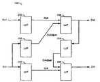
参照图1,示出了根据本发明优选实施例的实例系统100的图表。系统(或组件)100可以称为色调转换系统。色调转换系统100通常包括电路(或模块)102和电路(或模块)104。输入信号(例如,VIN)可以由电路102接收,亮度信号(例如,Y)可以从电路102传输到电路104。多颜色信号(例如,Cb0、Cr0、Cb3和Cr3)也可以从电路102传输到电路104。电路104可以生成并呈现输出信号(例如,VOUT)。Referring to FIG. 1 , a diagram of an
电路102可以称为校正电路。校正电路102可以用于调节颜色空间的一个或多个区域,以校正肤色、自然色和/或任意颜色区域。
信号VIN可以是一个或多个模拟视频信号和/或一个或多个数字视频信号。信号VIN通常包括逐行扫描格式帧和/或隔行扫描格式场的序列。信号VIN可以包括适于对显示和视频信息进行同步的同步信号。在模拟形式中,信号VIN可以生成为(但不限于)EIA-770(例如,YCrCb)信号。在数字形式中,信号VIN可以生成为(但不限于)高清多媒体接口(HDMI)信号、数字视频接口(DVI)信号、BT.601信号、和/或BT.656信号。信号VIN可以被格式化为标清信号或高清信号。 Signal VIN may be one or more analog video signals and/or one or more digital video signals. Signal VIN typically includes a sequence of frames in progressive scan format and/or fields in interlaced scan format. Signal VIN may include a synchronization signal suitable for synchronizing display and video information. In analog form, signal VIN may be generated as, but not limited to, an EIA-770 (eg, YCrCb) signal. In digital form, signal VIN may be generated as, but not limited to, a high-definition multimedia interface (HDMI) signal, a digital visual interface (DVI) signal, a BT.601 signal, and/or a BT.656 signal. The signal VIN can be formatted as a standard definition signal or a high definition signal. the
信号VOUT可以是一个或多个模拟视频信号和/或一个或多个数字视频信号。信号VOUT通常包括逐行扫描格式帧和/或隔行扫描格式场的序列。信号VOUT可以包括适于对显示和视频信息进行同步的同步信号。在模拟形式中,信号VOUT可以生成为(但不限于)RGB(红、绿、蓝)信号、EIA-770(例如,YCrCb)信号、S-视频信号和/或组合视频基带信号(CVBS)。在数字形式中,信号VOUT可以生成为(但不限于)高清多媒体接口(HDMI)信号、数字视频接口(DVI)信号、BT.601信号和/或BT.656信号。该信号VOUT可以被格式化为标清信号或高清信号。 Signal VOUT may be one or more analog video signals and/or one or more digital video signals. Signal VOUT typically includes a sequence of progressive format frames and/or interlaced format fields. Signal VOUT may include a synchronization signal suitable for synchronizing display and video information. In analog form, signal VOUT may be generated as, but not limited to, an RGB (red, green, blue) signal, an EIA-770 (eg, YCrCb) signal, an S-video signal, and/or a composite video baseband signal (CVBS). In digital form, signal VOUT may be generated as, but not limited to, a High-Definition Multimedia Interface (HDMI) signal, a Digital Visual Interface (DVI) signal, a BT.601 signal, and/or a BT.656 signal. The signal VOUT can be formatted as a standard definition signal or a high definition signal. the
信号Y通常表示信号VIN内视频的亮度分量。信号Cb0和Cb3可以携带视频的第一颜色(例如,蓝色)分量。信号Cr0和Cr3可以携带视频的第二颜色(例如,红色)分量。通常,信号Cb0和Cr0表示未被电路102修改过的颜色信息。信号Cb3和Cr3可以携带该视频的经校正的颜色信息。 Signal Y generally represents the luminance component of video within signal VIN. Signals Cb0 and Cb3 may carry a first color (eg, blue) component of video. Signals Cr0 and Cr3 may carry the second color (eg, red) component of the video. In general, signals Cb0 and Cr0 represent color information that has not been modified by
参照图2,示出了联合颜色空间122内的实例区域120的图表。由校正电路102执行色调校正的基本方法通常包括色度采样(仅仅)处理。可以在联合颜色空间122内(例如,Cb、Cr颜色空间)执行肤色识别。可以在具有落入联合颜色空间122中肤色识别区域(或分区)120内的颜色的像素上执行该识别。区域120的形状包括(但不限于)矩形(为了简单起见)作为检测/识别分区。为了其它可供选择的检测性能,可以实施诸如椭圆形、卵形和六边形的其它区域形状。在一些实施例中,可以预定区域120的形状、位置和数目。在另一些实施例中,可以在运行期间计算区域120的形状、位置和/或数目。 Referring to FIG. 2 , a diagram of an
由校正电路102执行的肤色处理通常是基于识别样本的Cr值和Cb值共同完成的。来自信号VIN的用于该处理的输入可以限于当前(像素)样本的Cb值和Cr值,以生成当前样本的校正值。在计算当前样本的校正值时,可以忽略相邻像素的颜色。 The skin color processing performed by the
单个目标颜色对124(例如,(mapCb,mapCr))可以被识别为检测区域120内带有颜色的所有样本的“理想的”代表性颜色点。检测区域120内样本的Cr值和Cb值可以通过分段线性函数进行映射,这将大大简化本发明的实施。也可以实施非线性函数以满足特殊应用的标准。 A single target color pair 124 (eg, (mapCb, mapCr)) may be identified as an "ideal" representative color point for all samples with color within the
位于检测区域120的内边界126内部的样本可以由固定的部分(fixed fraction)移动接近理想的颜色对124。内边界126可以定义中部区域128。与原Cr值和原Cb值相比,在接近理想的颜色对124时,该移动可以重新定位每个Cr值和Cb值两次。例如,中部区域128内的原(Cb,Cr)颜色样本130可以被移动到位置132。中部区域128内的移动典型地具有小于1的线性斜率。 Samples located inside the
边界区域134可以定义在检测区域120内且在中部区域128外。落入边界区域134内的样本(例如,样本136)可以连续地映射到检测区域120内的其它样本,使得输出颜色区域横跨整个输入颜色区域。 A border region 134 may be defined within the
可以沿检测区域120的周界定义过渡区域138。过渡区域138一般都虑及从检测区域120内到检测区域120外的颜色空间122的连续混合(扭曲(warping))。 A transition region 138 may be defined along the perimeter of the
再次参照图1,校正电路102通常包括电路(或模块)140,一个或多个电路(或模块)142a-142n以及电路(或模块)144。信号VIN可以由电路140接收。电路140可以将信号Y、Cb0和Cr0传输到转换电路104。电路142a-142n可以将信号Cb3和Cr3传输到转换电路104。电路142a-142n中的每一个电路都可以接收来自电路140的一对信号(例如,(Cb1a,Cr1a)直到(Cb1n,Cr1n),分别地)。电路144可以向电路142a-142n中的每一个电路传输信息。 Referring again to FIG. 1 ,
电路140可以称为分离电路。分离电路140可以用于基于信号VIN中接收的像素在颜色空间122内的位置对VIN中接收的像素进行分离。
电路142a-142n中的每一个均可以称为映射电路。映射电路142a-142n中的每一个都是可以用于在不同的检测区域120内映射从分离器电路140接收到的样本。每个不同的检测区域120、中部区域128、边界区域134和理想颜色点124可以基于由电路144提供的信息。 Each of
电路144可以称为存储电路。存储电路144可以存储(例如,永久地或动态地)定义一个或多个检测区域120的信息。在一些实施例中,映射信息可以设计在映射电路142a-142n内。
转换电路104通常包括电路(或模块)146和电路(或模块)148。电路146可以接收来自分离器电路140的信号Y、Cb0和Cr0。信号Cb3和Cr3可以由电路146从映射电路142a-142n接收。电路148可以输出信号VOUT。电路146可以将信号(例如,VOUT’)传输到电路148。 The
电路146可以称为组合电路。组合电路146可以用于通过组合来自信号Y、Cb0、Cr0、Cb3和Cr3的样本数据以生成信号VOUT’。信号VOUT’中的每个像素可以是信号Y中的亮度值和来自信号Cb0、Cr0或来自信号Cb3、Cr3(来自合适的映射电路142a-142n)的两个颜色值的组合。因此,信号VOUT’中的样本可以如同信号VIN中的样本一样位于原颜色空间(例如,YCbCr)内。
电路148可以称为颜色空间转换电路。颜色空间转换电路148可以用于改变信号VOUT’的颜色空间以产生信号VOUT。在一些实施例中,颜色空间转换电路148可以获得信号VOUT中预期的输出颜色空间(例如,RGB颜色空间)。在其它实施例中,在YCbCr颜色空间为预期的输出颜色空间(例如,VOUT=VOUT’)时,颜色空间转换电路148可以不存在。
参照图3,示出了用于处理样本的实例校正方法150的流程图。方法(或过程)150可以称为校正方法。校正方法150通常包括步骤(或块)152、步骤(或块)154和步骤(或块)156。步骤154通常包括步骤(或块)160、步骤(或块)162、步骤(或块)164、步骤(或块)166、步骤(或块)168、步骤(或块)170、步骤(或块)172、步骤(或块)174、步骤(或块)176以及步骤(或块) 178。校正方法150可以(i)就单个检测区域120进行描述,(ii)通常称信号Cb1a-Cb1n和Cr1a-Cr1n为Cb1和Cr1以及(iii)利用映射电路142a作为代表性示例。 Referring to FIG. 3 , a flowchart of an example calibration method 150 for processing samples is shown. Method (or process) 150 may be referred to as a calibration method. Calibration method 150 generally includes step (or block) 152 , step (or block) 154 and step (or block) 156 . Step 154 generally includes step (or block) 160, step (or block) 162, step (or block) 164, step (or block) 166, step (or block) 168, step (or block) 170, step (or block) ) 172, step (or block) 174, step (or block) 176 and step (or block) 178. Calibration method 150 may (i) be described in terms of a
在步骤152中,分离器电路140可以将每个单独的输入样本分离为信号Y中的亮度值、信号Cb1中的蓝色值和信号Cr1中的红色值。在步骤154中,映射电路142a可以将蓝色值校正为信号Cb3中新的蓝色值,并将将红色值校正为信号Cr3中新的红色值。在步骤156中,组合电路146将新的蓝色值和新的红色值与亮度值重新组合以生成信号VOUT’中的映射样本。 In step 152,
更详细地,肤色检测区域120可以包括样本(Cb,Cr),使得Cb∈[olBND...orBND]且Cr∈[obBND...otBND]。参数olBND、orBND、obBND和otBND可以分别定义肤色区域120的外左边界、外右边界、外底部边界和外顶部边界。 In more detail, the skin
中部区域128可以包含样本(Cb,Cr),使得Cb∈[ilBND...irBND]且Cr∈[ibBND...itBND],其中(i)BND=16或24或32以及(ii)ilBND=olBND+BND,irBND=orBND-BND,ibBND=obBND+BND以及itBND=otBND-BND。参数ilBND、irBND、ibBND和itBND可以分别定义中部区域128的内左边界、内右边界、内底部边界和内顶部边界。 The middle region 128 may contain samples (Cb, Cr) such that Cb ∈ [ilBND...irBND] and Cr ∈ [ibBND...itBND], where (i) BND = 16 or 24 or 32 and (ii) ilBND = olBND+BND, irBND=orBND-BND, ibBND=obBND+BND and itBND=otBND-BND. The parameters ilBND, irBND, ibBND, and itBND may define the inner left, inner right, inner bottom, and inner top boundaries of the middle region 128, respectively. the
过渡区域138可以包括离肤色区域120周界一段距离(例如,TBND)内的样本。参数TBND可以具有典型值16或24或32。“理想的”肤色点124通常包含在中部区域128内的位置(mapCb,mapCr)处。 The transition region 138 may include samples within a distance (eg, TBND) from the perimeter of the
过渡区域138可以包括离肤色区域120周界一段距离(例如,TBND)内的样本。参数TBND可以具有典型值16或24或32。“理想的”肤色点124通常包含在中部区域128内的位置(mapCb,mapCr)处。 The transition region 138 may include samples within a distance (eg, TBND) from the perimeter of the
校正步骤154通常包括四组步骤,在图中标示为A1、A2、B1和B2。组A1通常包括步骤160-164,组A2通常包括步骤166和168,组B1通常包括步骤170-174,组B2通常包括步骤176和178。 The calibration step 154 generally includes four sets of steps, labeled A1, A2, B1 and B2 in the figure. Group A1 generally includes steps 160-164, group A2 generally includes steps 166 and 168, group B1 generally includes steps 170-174, and group B2 generally includes steps 176 and 178. the
对于肤色区域120内的每个样本(Cb,Cr),可以通过映射电路142a经下面的步骤计算经调节的输出(例如,(Cb3,Cr3))。对于不在肤色区域120内的每个样本(Cb,Cr),输出可以与输入(例如,Cb3=Cb1且Cr3=Cr1)相同。通常不更改亮度值,否则皮肤种类可能被破坏。 For each sample (Cb, Cr) within the
在步骤160中,映射电路142a通常通过定标因子CbScale经等式1向理想的mapCb定标中部区域128(例如,Cb∈[ilBND...irBND])内的蓝色值Cb1,等式1如下: In step 160, the
Cb2=(Cb1-mapCb)×CbScale+mapCb 等式1 Cb2=(Cb1-mapCb)×CbScale+mapCb Equation 1
在一些实施例中,定标因子CbScale可以具有固定值(例如,CbScale=0.5)。 In some embodiments, the scaling factor CbScale may have a fixed value (eg, CbScale=0.5). the
在步骤162中,可以经等式2定标边界区域134的左侧内的蓝色值Cb1(例如,Cb∈[olBND...ilBND])以使映射连续,等式2如下: In step 162, the blue values Cb1 (e.g., Cb ∈ [olBND .
Cb2=(Cb1-olBND)×(BND+(mapCb-ilBND)×CbScale)/BND+olBND 等式2 Cb2=(Cb1-olBND)×(BND+(mapCb-ilBND)×CbScale)/BND+olBND Equation 2
在步骤164中,同样可以经等式3定标边界区域134的右侧内的蓝色值Cb1(例如,Cb∈[irBND...orBND])以使映射连续,等式3如下: In step 164, the blue values Cb1 (e.g., Cb ∈ [irBND .
Cb2=(Cb1-orBND)×(BND+(irBND-mapCb)×CbScale)/BND+orBND 等式3 Cb2=(Cb1-orBND)×(BND+(irBND-mapCb)×CbScale)/BND+orBND Equation 3
在过渡区域138内,可以经等式4和等式5以连续的方式执行映射转换的逐步混合,等式4和等式5如下: Within the transition region 138, stepwise mixing of mapping transitions can be performed in a continuous manner via Equations 4 and 5, which are as follows:
CbAdjust=min(TBND,min(otBND-Cr1,Cr1-obBND))等式4 CbAdjust=min(TBND, min(otBND-Cr1, Cr1-obBND)) Equation 4
[0050 Cb3=(Cb2×CbAdjust+Cb1×(TBND-CbAdjust))/TBND等式5Cb3 =(Cb2*CbAdjust+Cb1*(TBND-CbAdjust))/TBND equation 5
然后校正的蓝色值可以准备用于通过组合电路146而与亮度分量重新组合(例如,步骤156)。 The corrected blue value may then be ready for recombination with the luma component by combining circuit 146 (eg, step 156). the
在步骤170中,映射电路142a通常通过定标因子CrScale经等式6向理想的mapCr定标中部区域128(例如,Cr∈[ibBND...itBND])内的红色值Cr1,等式6如下: In step 170,
Cr2=(Cr1-mapCr)×CrScale+mapCr 等式6 Cr2=(Cr1-mapCr)×CrScale+mapCr Equation 6
在一些实施例中,定标因子CrScale可以具有固定值0.5。 In some embodiments, the scaling factor CrScale may have a fixed value of 0.5. the
在步骤172中,可以经等式7定标边界区域134的底侧内的红色值Cr1(例如,Cr∈[obBND...ibBND]),以使映射连续,等式7如下: In step 172, the red value Cr within the bottom side of the bounding region 134 may be scaled (e.g., Cr e [obBND . . . ibBND]) to make the mapping continuous via Equation 7, which is as follows:
Cr2=(Cr1-obBND)×(BND+(mapCr-ibBND)×CrScale)/BND+obBND 等式7 Cr2=(Cr1-obBND)×(BND+(mapCr-ibBND)×CrScale)/BND+obBND Equation 7
在步骤174中,同样可以经等式8定标边界区域134的顶侧内的红色值Cr1(例如,Cr∈[itBND...otBND]),以使映射连续,等式8如下: In step 174, the red value Cr within the top side of the border region 134 can also be scaled (e.g., Cr e [itBND . . . otBND]) via Equation 8 to make the mapping continuous, as follows:
Cr2=(Cr1-otBND)×(BND+(itBND-mapCr)×CrScale)/BND+otBND 等式8 Cr2=(Cr1-otBND)×(BND+(itBND-mapCr)×CrScale)/BND+otBND Equation 8
在过渡区域138内,可以经等式9和等式10以连续的方式执行映射转换的逐步混合,等式9和等式10如下: Within the transition region 138, stepwise mixing of mapping transformations can be performed in a continuous manner via Equations 9 and 10, which are as follows:
CrAdjust=min(TBND,min(orBND-Cb3,Cb3-olBND))等式9 CrAdjust=min(TBND, min(orBND-Cb3, Cb3-olBND)) Equation 9
Cr3=(Cr2*CrAdjust+Cr1*(TBND-CrAdjust))/TBND等式10 Cr3=(Cr2*CrAdjust+Cr1*(TBND-CrAdjust))/TBND equation 10
为了完全连续,等式9通常利用Cb3而不是Cb1。然后,经校正的红色值可以准备用于通过组合电路146与亮度分量和蓝色分量重新组合(例如,步骤156)。 For complete continuity, Equation 9 typically utilizes Cb3 instead of Cb1. The corrected red value may then be ready for recombination with the luminance and blue components by combining circuit 146 (eg, step 156). the
在一些实施例中,校正方法150可以在完成红色值Cr3的处理之前完成蓝色值Cb3的处理。步骤组A1和B1可以基本上同时地并行执行,而步骤组B2取决于Cb3的值,从而步骤组A2应该在步骤组B2之前完成。 In some embodiments, the correction method 150 may complete the processing of the blue value Cb3 before completing the processing of the red value Cr3. Step groups A1 and B1 can be executed substantially simultaneously in parallel, while step group B2 depends on the value of Cb3, so that step group A2 should be completed before step group B2. the
在其它实施例中,可以实施校正方法150以在完成蓝色值Cb3的处理之前完成红色值Cr3的处理。如前,步骤组A1和B1可以基本上同时地并行执行。然而,等式对(i)4和5以及等式对(ii)9和10可以修改,以使(i)步骤组A2取决于Cb2和Cr3(ii)步骤组B2取决于Cr2和Cb1。同样地,步骤组B2可以在步骤组A2开始之前完成。 In other embodiments, the correction method 150 may be implemented to complete the processing of the red value Cr3 before completing the processing of the blue value Cb3. As before, groups of steps A1 and B1 may be performed substantially simultaneously and in parallel. However, pair of equations (i) 4 and 5 and pair of equations (ii) 9 and 10 can be modified such that (i) step group A2 depends on Cb2 and Cr3 (ii) step group B2 depends on Cr2 and Cb1. Likewise, group of steps B2 may be completed before group of steps A2 begins. the
参照图4,示出了映射电路142(例如,电路142a)的实例实施的详细框图。映射电路142通常包括电路(或模块)200、电路(或模块)202、电路(或模块)204、电路(或模块)206、电路(或模块)208和电路(或模块)210。电路200可以接收蓝色分量信号Cb1(例如,信号Cb1a),电路202和204可以接收红色分量信号Cr1(例如,信号Cr1a),电路206可以输出校正蓝色分量信号Cb3,电路208可以输出校正红色分量信号Cr3,电路204可以向电路206输出蓝色调整值CbAdjust。电路210可以向电路208输出红色调整值CrAdjust。 Referring to FIG. 4 , a detailed block diagram of an example implementation of mapping circuitry 142 (eg,
电路200-210中的每一个可以单独称为查找电路。每个查找电路200-210可以用作查找表(LUT)。查找表可以用于自上级定标和调整各个值。该定标和调整可以是线性和/或非线性的,取决于查找表内的输入。然而,依然应当注意上述校正方法150结构。设计可以首先处理Cr1或Cb1。为了不失一般性,以下假定首先处理Cb1。 Each of circuits 200-210 may be individually referred to as a lookup circuit. Each lookup circuit 200-210 may function as a lookup table (LUT). A look-up table can be used to scale and adjust individual values from a higher level. This scaling and adjustment can be linear and/or non-linear, depending on the inputs in the lookup table. However, attention should still be paid to the correction method 150 structure described above. Designs can handle Cr1 or Cb1 first. Without loss of generality, the following assumes that Cb1 is dealt with first. the
对于检测区域120内的样本(Cb,Cr),查找电路200、204和206内的连续函数通常将特定范围内的Cb1值映射到同样全范围内的Cb3值。设计该映射,从而实现(i)关于期望的“理想的”点的范围压缩以及(ii)远离该理想的点的范围扩大(以维持连续映射)。该映射可以包括位于未在该区域内的Cr值的边界处的混合(例如,在过渡区域138中)。可以采用这种混合,使得进行上述映射的Cb值与未进行上述映射的Cb值(接近Cr边界)之间产生连续转换。 For samples (Cb, Cr) within
相似地,对Cr值可以应用查找电路202、210和208执行类似的处理。然而,最后的混合阶段应当利用已经处理过的Cb3值,以维持完全连续的映射。例如,组A2继组A1之后,组B1可以与组A1(或者A2)并行执行,组B2继组B1之后以及组B2继组A2之后。 Similarly,
参照图5,示出了分离电路140的示例性实施的详图。分离电路140通常包括电路(或模块)220、电路(或模块)222以及一个或多个电路(或模块)224a-224n。所有的电路224a-224n可以接收信号Cb和Cr。电路220可以将控制信号(例如,K0)输出给电路222,电路220也可以将一个或多个控制信号(例如,Ka-Kn)分别输出给电路224a-224n。电路224a-224n可以分别生成信号对Cb1a-Cb1n和Cr1a-Cr1n。 Referring to FIG. 5 , a detailed diagram of an exemplary implementation of the
电路220可以称为选择查找电路。电路222和224a-224n中的每一个电路均可以称为通过门(例如,逻辑AND门)。选择查找电路220可以用于确定颜色对(Cb,Cr)是否落入任意一个或多个检测区域120内。若没有,则维持控制信号K0使信号Cb和Cr通过通过门222而成为信号Cb0和Cr0。如果颜色对(Cb,Cr)落入一个或多个检测区域120内,则维持合适的控制信号Ka-Kn使得各通过门224a-224n向合适的映射电路142a-142n传送颜色值。
参照图6,示出了检测区域实例组的图表。本发明可以应用于除了肤色以外的颜色空间区域。特别地,可以在单个系统100内实施多个(例如,3个)并行映射电路142a-142n。分离电路140可以配置为识别并分离地校正色调的多个(例如,3个)不同分区120a-120f。例如,系统100可以同时解决肤色(例如,“海贝粉色”)、绿色(例如,“草绿”和/或“叶绿色”)和蓝色(例如,“天蓝”和/或“水蓝”)。通常,红色、黄色、紫色和其它颜色可以没有很多观察者可以有力断定的自然参照物对照。因此,如果不能合适地调节肤色区域、绿色区域和/或蓝色区域的颜色饱和度,则很多自然图片都可能显得不自然。此外,每个区域可能具有相同的或不同的形状(例如,矩形、饼形、三角形、卵形、椭圆形、六边形)。 Referring to FIG. 6 , a diagram of an example set of detection regions is shown. The invention can be applied to color space regions other than skin tones. In particular, multiple (eg, 3)
由图1、3、4和5执行的功能可以使用根据本说明书的教导而编程的传统的一般目的的数字计算机来实施,因为对相关领域的技术人员是显而易见的。基于当前披露的教导普通程序员可以很容易地准备合适的软件编码,这也是因为对相关领域的技术人员是显而易见的。 The functions performed by Figures 1, 3, 4 and 5 can be implemented using a conventional general purpose digital computer programmed in accordance with the teachings of this specification, as will be apparent to those skilled in the relevant art. Appropriate software coding can be readily prepared by an ordinary programmer based on the teachings of the present disclosure, as will be apparent to those skilled in the relevant arts. the
本发明可以通过ASICs、FPGAs的配备或者通过连接传统组成电路的网络实施,如在此所描述的对本领域的技术人员来说是显而易见的修改。 The invention may be implemented through the provisioning of ASICs, FPGAs, or through networking of conventional constituent circuits, with modifications apparent to those skilled in the art as described herein. the
因此本发明还可以包括计算机产品,该计算机产品可以为包含有指令的存储介质,所述指令可以用于对计算机进行编程以执行根据本发明的处理。该存储介质可以包括但不限于包括软盘光、CD-ROM、磁-光盘、ROMs、RAMs、EPROMs、EEPROMs、闪存、磁或光卡,或适于存储电子指令的任意类型的介质。如在此利用的,术语“同时地”意在描述共享相同时间段的事件,但该术语并不意味着限制于在相同时间点开始在相同时间点结束或具有相同持续时间的事件。 The invention thus also includes a computer product, which may be a storage medium containing instructions which can be used to program a computer to perform the process according to the invention. Such storage media may include, but are not limited to, floppy discs, CD-ROMs, magneto-optical discs, ROMs, RAMs, EPROMs, EEPROMs, flash memory, magnetic or optical cards, or any type of media suitable for storing electronic instructions. As utilized herein, the term "simultaneously" is intended to describe events that share the same time period, but the term is not meant to be limited to events that begin at the same point in time and end at the same point in time or have the same duration. the
尽管已经参照本发明的优选实施例特别示出并描述了本发明,但本领域的技术人员应当理解各种形式和细节的变换不脱离本发明的范围。 While the invention has been particularly shown and described with reference to its preferred embodiments, workers skilled in the art will understand that various changes in form and details would not depart from the scope of the invention. the
Claims (20)
Applications Claiming Priority (3)
| Application Number | Priority Date | Filing Date | Title |
|---|---|---|---|
| US11/504,166 | 2006-08-15 | ||
| US11/504,166US7821580B2 (en) | 2006-08-15 | 2006-08-15 | Contour free point operation for video skin tone correction |
| PCT/US2007/017908WO2008021314A2 (en) | 2006-08-15 | 2007-08-13 | Contour free point operation for video skin tone correction |
Publications (2)
| Publication Number | Publication Date |
|---|---|
| CN101506829A CN101506829A (en) | 2009-08-12 |
| CN101506829Btrue CN101506829B (en) | 2012-05-30 |
Family
ID=39082674
Family Applications (1)
| Application Number | Title | Priority Date | Filing Date |
|---|---|---|---|
| CN2007800303619AExpired - Fee RelatedCN101506829B (en) | 2006-08-15 | 2007-08-13 | Contour free point operation for video skin tone correction |
Country Status (6)
| Country | Link |
|---|---|
| US (2) | US7821580B2 (en) |
| EP (1) | EP2054842B1 (en) |
| JP (2) | JP5027233B2 (en) |
| KR (1) | KR101221013B1 (en) |
| CN (1) | CN101506829B (en) |
| WO (1) | WO2008021314A2 (en) |
Families Citing this family (9)
| Publication number | Priority date | Publication date | Assignee | Title |
|---|---|---|---|---|
| JP5121206B2 (en)* | 2006-10-23 | 2013-01-16 | オリンパス株式会社 | Image processing apparatus, image processing program, and image processing method |
| US20090180028A1 (en)* | 2008-01-15 | 2009-07-16 | David Wu | Method and system for 3-d color adjustment based on color region definition using pwl modules |
| US8553154B2 (en) | 2010-02-16 | 2013-10-08 | Vixs Systems, Inc | Method and/or apparatus for implementing a color management module |
| CN104581103B (en)* | 2013-10-21 | 2018-04-27 | 腾讯科技(深圳)有限公司 | A kind of image processing method and device |
| US9942489B2 (en)* | 2015-06-02 | 2018-04-10 | Samsung Electronics Co., Ltd. | Adaptive tone mapping based on local contrast |
| CN110248242B (en)* | 2019-07-10 | 2021-11-09 | 广州虎牙科技有限公司 | Image processing and live broadcasting method, device, equipment and storage medium |
| WO2021040907A1 (en)* | 2019-08-30 | 2021-03-04 | Alibaba Group Holding Limited | Method and system for signaling chroma quantization parameter table |
| KR20220154504A (en) | 2021-05-13 | 2022-11-22 | 권기범 | A chair that can adjust the backrest to itself |
| TWI871517B (en) | 2021-07-20 | 2025-02-01 | 美商Oled沃克斯有限責任公司 | Display with three regions of color space |
Citations (5)
| Publication number | Priority date | Publication date | Assignee | Title |
|---|---|---|---|---|
| US5191548A (en)* | 1990-03-14 | 1993-03-02 | C-Cube Microsystems | System for compression and decompression of video data using discrete cosine transform and coding techniques |
| CN1081874A (en)* | 1992-04-29 | 1994-02-16 | 布里斯托尔-米尔斯·斯奎布公司 | With 5,6-dihydroxyphenyl indole/chlorite hair dyeing |
| US6124899A (en)* | 1996-12-06 | 2000-09-26 | Ati International | Method and apparatus for encoding video color information |
| US20040264788A1 (en)* | 2003-06-24 | 2004-12-30 | Lsi Logic Corporation | Real time scene change detection in video sequences |
| US7057671B2 (en)* | 2002-01-30 | 2006-06-06 | At & T Corp | Image and video processing with chrominance attenuation |
Family Cites Families (7)
| Publication number | Priority date | Publication date | Assignee | Title |
|---|---|---|---|---|
| JPH0678320A (en) | 1992-08-25 | 1994-03-18 | Matsushita Electric Ind Co Ltd | Color adjustment device |
| US5568167A (en) | 1994-09-23 | 1996-10-22 | C-Cube Microsystems, Inc. | System for providing antialiased video overlays |
| US5559532A (en) | 1994-11-10 | 1996-09-24 | Lsi Logic, Inc. | Method and apparatus for parallel pixel hardware cursor |
| US5953691A (en) | 1996-10-11 | 1999-09-14 | Divicom, Inc. | Processing system with graphics data prescaling |
| JP2002016818A (en)* | 2000-04-28 | 2002-01-18 | Fuji Photo Film Co Ltd | Color correction method and device, and recording medium |
| JP4040625B2 (en)* | 2002-09-12 | 2008-01-30 | 松下電器産業株式会社 | Image processing apparatus, printer apparatus, photographing apparatus, and television receiver |
| JP4046647B2 (en)* | 2003-05-29 | 2008-02-13 | 松下電器産業株式会社 | Color adjustment apparatus and method |
- 2006
- 2006-08-15USUS11/504,166patent/US7821580B2/enactiveActive
- 2007
- 2007-08-13WOPCT/US2007/017908patent/WO2008021314A2/enactiveApplication Filing
- 2007-08-13KRKR1020097005213Apatent/KR101221013B1/ennot_activeExpired - Fee Related
- 2007-08-13JPJP2009524648Apatent/JP5027233B2/ennot_activeExpired - Fee Related
- 2007-08-13CNCN2007800303619Apatent/CN101506829B/ennot_activeExpired - Fee Related
- 2007-08-13EPEP07836767.9Apatent/EP2054842B1/enactiveActive
- 2010
- 2010-08-24USUS12/861,950patent/US8045062B2/ennot_activeExpired - Fee Related
- 2011
- 2011-12-22JPJP2011281046Apatent/JP5027332B2/ennot_activeExpired - Fee Related
Patent Citations (5)
| Publication number | Priority date | Publication date | Assignee | Title |
|---|---|---|---|---|
| US5191548A (en)* | 1990-03-14 | 1993-03-02 | C-Cube Microsystems | System for compression and decompression of video data using discrete cosine transform and coding techniques |
| CN1081874A (en)* | 1992-04-29 | 1994-02-16 | 布里斯托尔-米尔斯·斯奎布公司 | With 5,6-dihydroxyphenyl indole/chlorite hair dyeing |
| US6124899A (en)* | 1996-12-06 | 2000-09-26 | Ati International | Method and apparatus for encoding video color information |
| US7057671B2 (en)* | 2002-01-30 | 2006-06-06 | At & T Corp | Image and video processing with chrominance attenuation |
| US20040264788A1 (en)* | 2003-06-24 | 2004-12-30 | Lsi Logic Corporation | Real time scene change detection in video sequences |
Also Published As
| Publication number | Publication date |
|---|---|
| WO2008021314A3 (en) | 2008-04-24 |
| JP2012118534A (en) | 2012-06-21 |
| EP2054842A2 (en) | 2009-05-06 |
| US20080043033A1 (en) | 2008-02-21 |
| US20100315559A1 (en) | 2010-12-16 |
| JP2010500849A (en) | 2010-01-07 |
| EP2054842B1 (en) | 2015-03-18 |
| US7821580B2 (en) | 2010-10-26 |
| JP5027233B2 (en) | 2012-09-19 |
| US8045062B2 (en) | 2011-10-25 |
| EP2054842A4 (en) | 2011-11-23 |
| KR101221013B1 (en) | 2013-01-10 |
| CN101506829A (en) | 2009-08-12 |
| WO2008021314A2 (en) | 2008-02-21 |
| KR20090051754A (en) | 2009-05-22 |
| JP5027332B2 (en) | 2012-09-19 |
Similar Documents
| Publication | Publication Date | Title |
|---|---|---|
| CN101506829B (en) | Contour free point operation for video skin tone correction | |
| JP4209439B2 (en) | Image processing apparatus, image processing system, image processing method, image processing program, and integrated circuit device | |
| EP1720361A1 (en) | Apparatus for detecting, correcting and processing in hue, saturation and luminance directions | |
| US8625154B2 (en) | Apparatus and method for reproducing optimized preference color using candidate images and natural languages | |
| CN101061704B (en) | Color adjusting device and method | |
| CN101296383A (en) | Method and apparatus for displaying images with wide color gamut | |
| EP1858246A2 (en) | Image correction circuit, image correction method and image display | |
| KR20170074909A (en) | METHOD AND DEVICE FOR DISPLAYING IMAGE BASED ON METADATA, AND RECORDING MEDIUM THEREFOR | |
| US8330869B2 (en) | Image processing program, method and processor for adjusting luminance component and chrominance component | |
| WO2006085274A2 (en) | Method of displaying an image and correspond image-display system | |
| JP2006229925A (en) | Dynamic image saturation processing device | |
| CN114999363A (en) | Color shift correction method, device, equipment, storage medium and program product | |
| JP2002132225A (en) | Video signal correction device and multimedia computer system using the same | |
| JP2010245709A (en) | Color conversion table creation method and color conversion output device | |
| JP2007507961A (en) | Universal color decoder and method for decoding input signals for a multiple primary color display system | |
| KR102160247B1 (en) | Electronic apparatus and Method for controlling the electronic apparatus thereof | |
| TWI531246B (en) | Color adjustment method and its system | |
| JP2005204229A (en) | Image processing apparatus, image processing method, and image processing program | |
| KR100463831B1 (en) | Apparatus and method for optimizing image quality by using human visual characteristics | |
| JP4608509B2 (en) | Composite lookup table creation device, composite lookup table creation method, and printing device | |
| Pan et al. | P‐49: a gamut‐mapping algorithm with separate skin and non‐skin color preference controls for wide‐color‐gamut TV | |
| US20030214520A1 (en) | Real-time gradation control | |
| JPH09147098A (en) | Method and device for processing color image | |
| JP2004072758A (en) | Color processing apparatus, color processing method, and color processing program | |
| WO2011021241A1 (en) | Image processing device |
Legal Events
| Date | Code | Title | Description |
|---|---|---|---|
| C06 | Publication | ||
| PB01 | Publication | ||
| C10 | Entry into substantive examination | ||
| SE01 | Entry into force of request for substantive examination | ||
| C14 | Grant of patent or utility model | ||
| GR01 | Patent grant | ||
| C41 | Transfer of patent application or patent right or utility model | ||
| TR01 | Transfer of patent right | Effective date of registration:20160720 Address after:Singapore Singapore Patentee after:Avago Technologies General IP (Singapore) Pte. Ltd. Address before:California, USA Patentee before:LSI Corp. | |
| TR01 | Transfer of patent right | Effective date of registration:20181018 Address after:Singapore Singapore Patentee after:Avago Technologies General IP (Singapore) Pte. Ltd. Address before:Singapore Singapore Patentee before:Avago Technologies General IP (Singapore) Pte. Ltd. | |
| TR01 | Transfer of patent right | ||
| CF01 | Termination of patent right due to non-payment of annual fee | Granted publication date:20120530 | |
| CF01 | Termination of patent right due to non-payment of annual fee |