CN101505988B - Electric vehicle control apparatus - Google Patents
Electric vehicle control apparatusDownload PDFInfo
- Publication number
- CN101505988B CN101505988BCN200680055568.7ACN200680055568ACN101505988BCN 101505988 BCN101505988 BCN 101505988BCN 200680055568 ACN200680055568 ACN 200680055568ACN 101505988 BCN101505988 BCN 101505988B
- Authority
- CN
- China
- Prior art keywords
- set value
- control unit
- vehicle
- load
- power storage
- Prior art date
- Legal status (The legal status is an assumption and is not a legal conclusion. Google has not performed a legal analysis and makes no representation as to the accuracy of the status listed.)
- Active
Links
Images


Classifications
- B—PERFORMING OPERATIONS; TRANSPORTING
- B60—VEHICLES IN GENERAL
- B60L—PROPULSION OF ELECTRICALLY-PROPELLED VEHICLES; SUPPLYING ELECTRIC POWER FOR AUXILIARY EQUIPMENT OF ELECTRICALLY-PROPELLED VEHICLES; ELECTRODYNAMIC BRAKE SYSTEMS FOR VEHICLES IN GENERAL; MAGNETIC SUSPENSION OR LEVITATION FOR VEHICLES; MONITORING OPERATING VARIABLES OF ELECTRICALLY-PROPELLED VEHICLES; ELECTRIC SAFETY DEVICES FOR ELECTRICALLY-PROPELLED VEHICLES
- B60L9/00—Electric propulsion with power supply external to the vehicle
- B60L9/16—Electric propulsion with power supply external to the vehicle using AC induction motors
- B60L9/18—Electric propulsion with power supply external to the vehicle using AC induction motors fed from DC supply lines
- B—PERFORMING OPERATIONS; TRANSPORTING
- B60—VEHICLES IN GENERAL
- B60L—PROPULSION OF ELECTRICALLY-PROPELLED VEHICLES; SUPPLYING ELECTRIC POWER FOR AUXILIARY EQUIPMENT OF ELECTRICALLY-PROPELLED VEHICLES; ELECTRODYNAMIC BRAKE SYSTEMS FOR VEHICLES IN GENERAL; MAGNETIC SUSPENSION OR LEVITATION FOR VEHICLES; MONITORING OPERATING VARIABLES OF ELECTRICALLY-PROPELLED VEHICLES; ELECTRIC SAFETY DEVICES FOR ELECTRICALLY-PROPELLED VEHICLES
- B60L1/00—Supplying electric power to auxiliary equipment of vehicles
- B60L1/003—Supplying electric power to auxiliary equipment of vehicles to auxiliary motors, e.g. for pumps, compressors
- B—PERFORMING OPERATIONS; TRANSPORTING
- B60—VEHICLES IN GENERAL
- B60L—PROPULSION OF ELECTRICALLY-PROPELLED VEHICLES; SUPPLYING ELECTRIC POWER FOR AUXILIARY EQUIPMENT OF ELECTRICALLY-PROPELLED VEHICLES; ELECTRODYNAMIC BRAKE SYSTEMS FOR VEHICLES IN GENERAL; MAGNETIC SUSPENSION OR LEVITATION FOR VEHICLES; MONITORING OPERATING VARIABLES OF ELECTRICALLY-PROPELLED VEHICLES; ELECTRIC SAFETY DEVICES FOR ELECTRICALLY-PROPELLED VEHICLES
- B60L1/00—Supplying electric power to auxiliary equipment of vehicles
- B60L1/02—Supplying electric power to auxiliary equipment of vehicles to electric heating circuits
- B60L1/04—Supplying electric power to auxiliary equipment of vehicles to electric heating circuits fed by the power supply line
- B60L1/06—Supplying electric power to auxiliary equipment of vehicles to electric heating circuits fed by the power supply line using only one supply
- B60L1/08—Methods and devices for control or regulation
- B—PERFORMING OPERATIONS; TRANSPORTING
- B60—VEHICLES IN GENERAL
- B60L—PROPULSION OF ELECTRICALLY-PROPELLED VEHICLES; SUPPLYING ELECTRIC POWER FOR AUXILIARY EQUIPMENT OF ELECTRICALLY-PROPELLED VEHICLES; ELECTRODYNAMIC BRAKE SYSTEMS FOR VEHICLES IN GENERAL; MAGNETIC SUSPENSION OR LEVITATION FOR VEHICLES; MONITORING OPERATING VARIABLES OF ELECTRICALLY-PROPELLED VEHICLES; ELECTRIC SAFETY DEVICES FOR ELECTRICALLY-PROPELLED VEHICLES
- B60L50/00—Electric propulsion with power supplied within the vehicle
- B60L50/40—Electric propulsion with power supplied within the vehicle using propulsion power supplied by capacitors
- B—PERFORMING OPERATIONS; TRANSPORTING
- B60—VEHICLES IN GENERAL
- B60L—PROPULSION OF ELECTRICALLY-PROPELLED VEHICLES; SUPPLYING ELECTRIC POWER FOR AUXILIARY EQUIPMENT OF ELECTRICALLY-PROPELLED VEHICLES; ELECTRODYNAMIC BRAKE SYSTEMS FOR VEHICLES IN GENERAL; MAGNETIC SUSPENSION OR LEVITATION FOR VEHICLES; MONITORING OPERATING VARIABLES OF ELECTRICALLY-PROPELLED VEHICLES; ELECTRIC SAFETY DEVICES FOR ELECTRICALLY-PROPELLED VEHICLES
- B60L50/00—Electric propulsion with power supplied within the vehicle
- B60L50/50—Electric propulsion with power supplied within the vehicle using propulsion power supplied by batteries or fuel cells
- B60L50/51—Electric propulsion with power supplied within the vehicle using propulsion power supplied by batteries or fuel cells characterised by AC-motors
- B—PERFORMING OPERATIONS; TRANSPORTING
- B60—VEHICLES IN GENERAL
- B60L—PROPULSION OF ELECTRICALLY-PROPELLED VEHICLES; SUPPLYING ELECTRIC POWER FOR AUXILIARY EQUIPMENT OF ELECTRICALLY-PROPELLED VEHICLES; ELECTRODYNAMIC BRAKE SYSTEMS FOR VEHICLES IN GENERAL; MAGNETIC SUSPENSION OR LEVITATION FOR VEHICLES; MONITORING OPERATING VARIABLES OF ELECTRICALLY-PROPELLED VEHICLES; ELECTRIC SAFETY DEVICES FOR ELECTRICALLY-PROPELLED VEHICLES
- B60L2200/00—Type of vehicles
- B60L2200/26—Rail vehicles
- Y—GENERAL TAGGING OF NEW TECHNOLOGICAL DEVELOPMENTS; GENERAL TAGGING OF CROSS-SECTIONAL TECHNOLOGIES SPANNING OVER SEVERAL SECTIONS OF THE IPC; TECHNICAL SUBJECTS COVERED BY FORMER USPC CROSS-REFERENCE ART COLLECTIONS [XRACs] AND DIGESTS
- Y02—TECHNOLOGIES OR APPLICATIONS FOR MITIGATION OR ADAPTATION AGAINST CLIMATE CHANGE
- Y02T—CLIMATE CHANGE MITIGATION TECHNOLOGIES RELATED TO TRANSPORTATION
- Y02T10/00—Road transport of goods or passengers
- Y02T10/60—Other road transportation technologies with climate change mitigation effect
- Y02T10/70—Energy storage systems for electromobility, e.g. batteries
Landscapes
- Engineering & Computer Science (AREA)
- Power Engineering (AREA)
- Transportation (AREA)
- Mechanical Engineering (AREA)
- Life Sciences & Earth Sciences (AREA)
- Sustainable Development (AREA)
- Sustainable Energy (AREA)
- Electric Propulsion And Braking For Vehicles (AREA)
Abstract
Translated fromChinese
Description
Translated fromChinese技术领域technical field
本发明涉及逆变器驱动的电车的控制装置,特别是涉及装设有进行直流电力的充放电的电力储存部的逆变器驱动的电车的控制装置。The present invention relates to a control device for an inverter-driven electric vehicle, and more particularly to a control device for an inverter-driven electric vehicle equipped with a power storage unit for charging and discharging DC power.
背景技术Background technique
近年来,在逆变器驱动的电车中,已知有一种电池驱动的电车,其结构为:在该电车上装设由电池等电力储存设备形成的电力储存部,可以从该电力储存部向控制车轮驱动用的电动机的逆变器提供电力;电车即使在没有架线的地段也可以行驶。(例如参照专利文献1)In recent years, among electric cars driven by inverters, a battery-driven electric car has been known. Its structure is: a power storage unit formed by a power storage device such as a battery is installed on the electric car, and the power storage unit can be transmitted from the power storage unit to the control unit. The inverters of the electric motors used to drive the wheels provide electricity; the tram can run even in areas without overhead wires. (For example, refer to Patent Document 1)
最近,正在积极开发充电电池、双电层电容器等电力储存设备,力图将蓄电量增大,但为了得到使电车行驶的充分电能,就目前的技术而言,需要体积相当大、重量相当重的电力储存部。然而,由于装设于电车的空间只限于底板下等,需要尽可能抑制电力储存部的尺寸、质量,往往难以确保充裕的蓄电量。因此,有效利用有限的储存电力是必要且必须的。Recently, power storage devices such as rechargeable batteries and electric double-layer capacitors are being actively developed to increase the storage capacity. However, in order to obtain sufficient power for running electric cars, current technologies require relatively large and heavy electric power storage devices. Power Storage Division. However, since the space installed in the train is limited to the underfloor, etc., it is necessary to keep the size and mass of the power storage unit as small as possible, and it is often difficult to secure a sufficient storage capacity. Therefore, it is necessary and necessary to effectively utilize the limited stored power.
另一方面,作为在没有架线的地段行驶的电车的适用例,例如路面电车最被看好,路面电车用的电车以来自上述电力储存部的电力就可以行驶,可以去除已有路线的一部分地段的架线,不需要架线或支柱,因此改善了景致。特别是铺设在名胜古迹周围的路线,拆下架线和支柱非常有助于改善景致。另外,从已有路线延长路线时,若距离不长,可以只延长线路而不铺设架线,也有可以缩短工程费用和工期的优点。On the other hand, as an application example of a tram running in a section without wires, for example, a streetcar is the most promising, and the tram for the streetcar can run on the electric power from the above-mentioned power storage unit, and a part of the existing route can be eliminated. The rigging does not require rigging or pillars, thus improving the view. Especially for routes laid around places of interest, removal of overhead wires and pillars is very helpful in improving the view. In addition, when extending the route from the existing route, if the distance is not too long, the route can be extended without laying wires, which also has the advantage of shortening the construction cost and construction period.
然而,由于路面电车与汽车共用行驶路面,受到汽车的堵塞等的影响,在没有架线的地段的行驶时间、停车时间会延长,由于这类原因,其运行形态与能以预先决定的运行时刻表行驶的通常的铁路电车不同。However, since streetcars and automobiles share the same road surface, the traveling time and parking time in areas without wires will be prolonged due to the influence of automobile congestion, etc. It is different from normal railroad trains that run on the table.
因此,考虑到在没有架线的地段的行驶时间、停止时间会延长,必须估计留出余量,存在的问题是:装设的电力储存部的容量需要比通常需要的容量更大。Therefore, it is necessary to estimate a margin in consideration of the longer travel time and stop time in areas where there are no wires, and there is a problem that the capacity of the installed power storage unit needs to be larger than the usual capacity.
并且也要考虑到在堵塞严重,不得不长时间停车时,装设在电车上的空调装置(制冷装置、供暖装置)会消耗电力储存部的储存电力,电车行驶所需的电能不足,导致电车不能行驶,在没有架线的地段进退不得的情况。In addition, it should also be considered that when the traffic is severely blocked and has to be parked for a long time, the air-conditioning device (refrigeration device, heating device) installed on the tram will consume the stored power of the power storage part, and the electric energy required for the tram to run is insufficient, resulting in a It cannot be driven, and it cannot advance or retreat in a section without wires.
专利文献1:日本专利特开2006-101698(参照图9及段落(0026))Patent Document 1: Japanese Patent Laid-Open No. 2006-101698 (see FIG. 9 and paragraph (0026))
发明内容Contents of the invention
本发明为解决以上的问题而作,本发明的目的是提供一种电车的控制装置,电车即使在没有架线的地段停留长于预先假定的时间时,该装置也能确保电车可以行驶到有架线的地段的电能。The present invention is made to solve the above problems. The purpose of the present invention is to provide a control device for electric cars, which can ensure that the electric cars can travel to the point where there are wires even if the electric car stays longer than the preset time. The electric energy of the lot of the line.
本发明的电车的控制装置的特征是,在包括:驱动电动机的第一逆变器;向负载提供电力的第二逆变器;向上述第一及第二逆变器提供电力的电力储存装置的电车中,设置有可根据上述电力储存装置的蓄电量或者状态量控制上述负载量的负载控制部。The electric vehicle control device of the present invention is characterized by comprising: a first inverter for driving a motor; a second inverter for supplying electric power to a load; and an electric power storage device for supplying electric power to the first and second inverters. The electric car of is provided with a load control unit capable of controlling the load amount based on the storage amount or state quantity of the power storage device.
本发明的电车的控制装置,即使电车在没有架线的地段停留长于预先假定的时间,也能确保可以行驶到有架线的地段的电能。The electric car control device of the present invention can ensure the electric energy that can travel to the location with the wire even if the electric car stays longer than the preset time in the location without the wire.
附图说明Description of drawings
图1是表示本发明的实施方式1的电车的控制装置的结构例的图。FIG. 1 is a diagram showing a configuration example of a control device for an electric vehicle according to Embodiment 1 of the present invention.
图2是表示本发明的实施方式1的负载控制部的结构例的图。2 is a diagram showing a configuration example of a load control unit according to Embodiment 1 of the present invention.
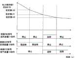
图3是表示本发明的实施方式1的送风装置、空调装置和换气装置在制冷时的动作的图。3 is a diagram showing the operation of the air blower, the air conditioner, and the ventilator during cooling according to Embodiment 1 of the present invention.
图4是表示本发明的实施方式的送风装置、空调装置和换气装置在供暖时的动作的图。Fig. 4 is a diagram showing the operation of the air blower, the air conditioner, and the ventilation device during heating according to the embodiment of the present invention.
具体实施方式Detailed ways
实施方式1.Implementation mode 1.
图1是表示本发明的实施方式1所涉及的电车的控制装置的结构例的图。图1中,该电车的控制装置的结构为可以从架线1通过导电弓2、车轮3、轨道4引入电力,通过电车的控制装置20驱动电动机6,并且可以向送风装置11、空调装置12、换气装置13等负载提供电力。另外,图1表示电车在没有架线1的地段行驶的状态。FIG. 1 is a diagram showing a configuration example of a control device for an electric vehicle according to Embodiment 1 of the present invention. In Fig. 1, the structure of the control device of the electric car is that the electric power can be introduced from the trolley 1 through the pantograph 2, the wheel 3, and the track 4, and the electric motor 6 can be driven by the
上述电车的控制装置20由驱动电动机6的可变电压、可变频率(VVVF)逆变器5;连接在DC/DC变换器8上的电力储存部7;控制上述DC/DC变换器和电力储存部7的控制部9;向上述负载即送风装置11、空调装置12、换气装置13提供电力的一定电压、一定频率(CVCF)逆变器10构成。在上述控制部9包括测定上述电力储存部7的蓄电量,控制上述负载的负载量的负载控制部9A。另外,也从CVCF逆变器10向车内的荧光灯、广播装置等负载提供电力(未图示),但由于其耗电量较小,此处从略。上述电力储存部7由双电层电容器或充电电池等电力储存设备构成,由于装设空间的限制,其蓄电量在目前的技术下极限为50KWh左右。The
图2是表示本发明实施方式1的负载控制部9A的结构例的图。如图所示,负载控制部9A设置在控制部9的内部,测定电力储存部7的蓄电量(以下记为SOC),将该SOC与内部的设定值LV0、LV1、LV2比较,根据其结果输出控制信号FNC、ACC、VTC,通过向送风装置11、空调装置12、换气装置13输入,可控制它们的运转。关于其具体的控制逻辑,将基于图3、图4在后文进行说明。SOC是State of charge(充电状态)的简称,是以充满电时作为100%的蓄电量的比例。若蓄电量消耗1/2,则SOC=50%,完全放电时SOC=0%。该SOC可以从电力储存部7的端子电压或充放电电流计算出,其各种结构作为已知技术存在。FIG. 2 is a diagram showing a configuration example of a
本发明的特征是,可根据上述电力储存部7的蓄电量,从控制部9直接或者间接控制送风装置11、空调装置12、换气装置13。The present invention is characterized in that the
所谓直接是指如图1所示的结构所示,表示从控制部9的负载控制部9A直接向送风装置11、空调装置12、换气装置13提供控制信号FNC、ACC、VTC的结构;所谓间接是指,在控制部9之外,另外设置能够汇集车辆内各个设备的信息,控制各个设备的车辆管理控制装置(未图示),设置向该车辆管理控制装置内输入蓄电量的信息的负载控制部9A,形成通过上述负载控制部9A控制送风装置11、空调装置12、换气装置13的结构。So-called direct means as shown in the structure shown in Figure 1, represents the structure that control signal FNC, ACC, VTC is provided directly to
本发明的结构可以是上述的直接、间接的控制结构的任意一种。另外,该结构也可以是送风装置11、空调装置12、换气装置13接入控制部9或者车辆管理控制装置内的负载控制部9A,分别独立掌握蓄电量,并与其相应地分别控制运转状态。总之,其结构为可根据电力储存部7的蓄电量,从负载控制部9A控制送风装置11、空调装置12、换气装置13。The structure of the present invention can be any one of the above-mentioned direct and indirect control structures. In addition, this structure may also be such that the
下面参照图1说明这样构成的电车的控制装置20的动作。电车在有架线的地段行驶时,从架线1和轨道4通过导电弓2和车轮3,向电车的控制装置20引入直流电力,通过VVVF逆变器5驱动电动机6,通过CVCF逆变器10向送风装置11、空调装置12、换气装置13提供电力,进行运转。Next, the operation of the electric
另一方面,电车在没有架线的地段行驶时(图1所示的状态时),可使用储存在配置于电车的控制装置20内部的电力储存部7的电力,通过VVVF逆变器5驱动电动机6,通过CVCF逆变器10向送风装置11、空调装置12、换气装置13提供电力。On the other hand, when the electric car is running in a section without overhead wires (in the state shown in FIG. 1 ), it can be driven by the
另外,电车在有架线的地段行驶时,对电力储存部7的充电可以通过DC/DC变换器8进行,虽然未图示,也可以在车站停车时等通过外部的充电装置充电,也可以在车站停车时等与已经充好电的电力储存部交换,其形态没有限定。In addition, when the electric car is running in a section with overhead wires, the charging of the power storage unit 7 can be performed by the DC/DC converter 8. Although not shown in the figure, it can also be charged by an external charging device when it is parked at a station, or it can be It is exchanged with the already-charged power storage unit when stopping at a station, etc., and its form is not limited.
图1中,空调装置12是制冷装置与供暖装置的总称,是分别用于将电车的车厢内的温度维持在舒适温度的装置。制冷装置的结构如一般已知的结构,是可以利用电动机驱动压缩机使制冷剂循环,传输热量的装置,从室内侧热交换器吸收室内的热量,并将吸收的热量从室外侧热交换器散热。已知室内侧热交换器、室外侧热交换器分别利用室内风扇、室外风扇积极使空气循环。供暖装置的结构通常也广为人知,有的由电热丝构成,还有的由半导体发热体等构成。另外,作为与制冷装置相反的结构,也可以是将室外的热传输至室内进行供暖的热泵式供暖装置。In FIG. 1 , an
此处,在下面说明空调装置12(制冷装置、供暖装置)的耗电量。Here, the power consumption of the air conditioner 12 (cooling device, heating device) will be described below.
装设在一辆一般的路面电车的制冷装置的耗电功率是15KW左右。所以,在夏季全负荷运转时的耗电量是15KWh左右。特别是驱动压缩机的电动机的耗电功率几乎就占10KW左右,室外风扇、室内风扇的耗电功率是几十W~几百W左右,相对于总体耗电功率的比例只是一点儿。另外,装设在一辆一般的路面电车上的供暖装置的耗电量也大致相同,在冬季供暖装置全负荷运转时的耗电量也是15KWh左右。即空调装置12在夏季、冬季都消耗15KWh左右的电能。The power consumption of the cooling device installed in a common streetcar is about 15KW. Therefore, the power consumption during full-load operation in summer is about 15KWh. In particular, the power consumption of the motor driving the compressor is almost 10KW, and the power consumption of outdoor fans and indoor fans is about tens to hundreds of W, which is only a small proportion to the overall power consumption. In addition, the power consumption of the heating device installed on a general streetcar is roughly the same, and the power consumption of the heating device in full load operation in winter is about 15KWh. That is, the
另一方面,如上所述,电力储存部7的蓄电量是50KWh左右,在只使空调装置12全负荷开动时,在50KWh/15KWh=3.3小时,所有储存在电力储存部7的电力会被完全消耗。实际上,若将所有电力储存部7的储存电力完全放电,会使构成电力储存部7的充电电池永久变质,所以最大也只能放电至全部容量的70%左右。所以,在不使充电电池永久变质的范围内用完蓄电量的时间为3.3小时×0.7=2.3小时。On the other hand, as mentioned above, the storage capacity of the power storage unit 7 is about 50KWh. When only the
另外,送风装置11是设置在车内的所谓风扇,换气装置13是将车内的空气排出至车外,将车外的空气吸进车内的装置。其耗电功率是各几十W左右,与空调装置12的耗电功率相比非常小,是1/100以下。空调装置12考虑制冷装置时,内置其中的室内风扇的耗电功率是几十W~百W左右,非常小,这一点如上所述。In addition, the
接下来,在下面说明行驶所需的电能。Next, electric energy required for running will be described below.
一般的路面电车的电动机6的额定输出是120KW左右,在连续进行该输出时,在不使充电电池永久变质的范围内用完储存的电力的时间是50KWh×0.7/120KWh=17.5分钟左右。这样,可知空调装置12消耗的电能超过行驶所需的电能的16%,是无法忽视的较多的电能。The rated output of the electric motor 6 of a general streetcar is about 120KW, and when this output is performed continuously, the time to use up the stored electric power within the range that does not permanently deteriorate the rechargeable battery is about 50KWh×0.7/120KWh=17.5 minutes. Thus, it can be seen that the electric energy consumed by the
另外,电车即使在停车时,空调装置12为维持车内温度,会继续消耗电力。因此,装设在电车上的电力储存部7的容量,考虑到在没有架线的地段的行驶时间、停止时间会延长,必须留有余量,存在的问题是,需要比通常所需的容量大的容量。In addition, even when the train is stopped, the
并且也必须考虑在堵塞严重,不得不长时间停车时,由于装设在电车上的空调装置12会消耗电力储存部7的储存电力,电车的行驶所需的电能不足,导致无法驱动电动机6,电车在没有架线的地段进退不得的情况发生的可能性。And it must also be considered that when the traffic jam is serious and has to be parked for a long time, since the
因此,在本发明中,采用根据电力储存部7的SOC,控制空调装置12、送风装置11、换气装置13的结构,解决上述的问题。Therefore, in the present invention, the above-mentioned problems are solved by adopting a configuration in which the
下面说明具体的控制方法。图3是表示本发明的实施方式的送风装置11、空调装置12和换气装置13的动作的图。图3表示在夏季,在开动空调装置12(制冷装置)的状态下,由于堵塞等影响,电车在没有架线1的地段长时间停车,SOC慢慢下降的状态。如图3所示,若电力储存部7的SOC低于最初的设定值LV0,负载控制部9A利用向空调装置12发送的信号ACC,将空调装置12从强运转切换至弱运转。以此降低耗电量,因此SOC的减少率变缓。A specific control method will be described below. Fig. 3 is a diagram showing the operation of the
若SOC进一步低于第二设定值LV1,负载控制部9A利用信号ACC使空调装置12停止。同时,为维持车内的温度环境,利用信号FNC起动送风装置11,为进一步防止车内温度上升,利用信号VTC使换气装置13运转。此时,空调装置12也可以只停止压缩机用的电动机和室外风扇,使耗电功率非常小的室内风扇继续运转。通过这样,至少可以向室内送风,因此可以将车内的舒适性维持在最低限度。SOC进一步下降,低于第三设定值LV2时,负载控制部9A利用信号FNC停止送风装置11,只使换气装置13运转。If the SOC is further lower than the second set value LV1, the
为抑制车内温度上升,较为理想的办法是,换气装置13在SOC下降时也继续运转。In order to suppress the temperature rise in the vehicle, it is desirable that the
图4是表示本发明的实施方式的送风装置11、空调装置12和换气装置13的动作的图。图4表示在冬季,在使空调装置12(供暖装置)开动的状态下,由于堵塞等影响,电车在没有架线1的地段长时间停车,SOC慢慢下降的状态。Fig. 4 is a diagram showing the operation of the
如图4所示,若电力储存部7的SOC低于最初的设定值LV0,负载控制部9A利用信号ACC将空调装置12从强运转切换至弱运转。据此降低耗电量,因此SOC的减少率变缓。若SOC进一步低于第二设定值LV1,则负载控制部9A利用信号ACC使空调装置12停止。另外,由于在冬季不需要送风装置11,较为理想的是使其停止,换气装置13在不必特别换气时也使其停止。As shown in FIG. 4 , when the SOC of power storage unit 7 is lower than the initial set value LV0 ,
另外,以上所示的第一设定值LV0、第二设定值LV1、第三设定值LV2可以是预先设定的一定值,也可以是可根据条件改变的值。例如,若使该值根据电车到达有架线的地段的剩余距离或时间改变,则可以最大程度确保空调装置12的运转,因此能在更长的时间维持车内环境。另外,该结构当然也可以是即使电力储存部7的蓄电量SOC低于第一设定值LV0、第二设定值LV1、第三设定值LV2,电车到达有架线1的地段,可以从架线1接收电力时,再起动空调装置12的运转,或返回强运转。可以将是否可从架线1接收电力输入至负载控制部9A,也可以根据电力储存部7的SOC增加判断负载控制部9A从架线1接收电力。In addition, the above-mentioned first set value LV0 , second set value LV1 , and third set value LV2 may be preset constant values, or may be values that can be changed according to conditions. For example, if the value is changed according to the remaining distance or time until the train arrives at a stretched area, the operation of the
这样,即使电车在没有架线的地段长时间停车时,通过抑制空调装置12消耗的蓄电量,抑制电力储存部7的SOC的下降,能够尽可能维持车内温度环境,确保用于电车行驶的电能。In this way, even when the electric car stops for a long time in a section without overhead wires, by suppressing the power storage amount consumed by the
据此确保电车的行驶所需的电能,从而可以使电车行驶到有架线的地段。并且,不必为防备电车在没有架线的地段的长时间停车,在电力储存部7的蓄电量上保留较大的余量,可以将电力储存部7在所需的最小限度上小型化。According to this, the electric energy required for the running of the electric car can be ensured, so that the electric car can be driven to the section where there is a wire. In addition, there is no need to reserve a large margin in the storage capacity of the power storage unit 7 in case the electric car stops for a long time in a location without overhead wires, and the power storage unit 7 can be miniaturized to the minimum necessary.
在本实施方式中,将空调装置12设定为强运转、弱运转、停止的三档进行控制,但也可以从强运转到停止连续控制。另外,虽然使送风装置11、换气装置12在SOC低于第二设定值LV1时仍然运转,但如已经描述的那样,由于其耗电功率较小,在SOC高于第二设定值LV1时也可以使其运转。In the present embodiment, the
另外,图1表示:控制送风装置11、空调装置12和换气装置13的负载控制部9A内置在控制DC/DC变换器8和电力储存部7的控制部9内,将电力储存部7的蓄电量传输至上述负载控制部9A,但并不限于此,只要能掌握电力储存部7的SOC,负载控制部9A也可以内置在未图示VVVF逆变器5的控制部或CVCF逆变器10的控制部内,还可以内置在包含这些构件的控制部(未图示)内。In addition, FIG. 1 shows that a
另外,也可以是从负载控制部9A向具有汇集车辆内的各个设备的动作信息根据状况控制各个设备的功能的车辆管理控制装置(未图示)传送SOC的信息的结构。Also, a configuration may be adopted in which SOC information is transmitted from the
反之,也可以是送风装置11、空调装置12、换气装置13接入负载控制部9A或者车辆管理控制装置,独立掌握SOC并与其相应地分别控制自身的运转状态的结构。Conversely, the
另外,在本实施方式中,表示了根据电力储存部7的蓄电量SOC进行负载的控制的结构,但例如也可以从电力储存部7的电压等状态量算出蓄电量。作为一个例子,适合作为电力储存部7的双电层电容器可以容易地从其电压算出蓄电量。所以,本实施方式不限于根据SOC进行负载控制的方式,将SOC替换为电力储存部7的电压等状态量的结构当然也可以进行实施。In addition, in this embodiment, a configuration is shown in which the load is controlled based on the storage amount SOC of the power storage unit 7 , but the storage amount may be calculated from state quantities such as the voltage of the power storage unit 7 , for example. As an example, an electric double layer capacitor suitable as the electric power storage unit 7 can easily calculate the stored amount from its voltage. Therefore, the present embodiment is not limited to the method of controlling the load based on the SOC, and it is of course also possible to implement a configuration in which the SOC is replaced by a state quantity such as the voltage of the power storage unit 7 .
图1中,表示了包含具有VVVF逆变器5、DCDC变换器8、电力储存部7、CVCF逆变器10、负载控制部9A的控制部9的设备结构作为电车的控制装置20,但如上所述,将负载控制部9A设置在车辆管理控制装置(未图示)时,或者设置在送风装置11、空调装置12、换气装置13的至少任意一个时,这些装置的负载控制部9A包含在电车的控制装置20的范围内。总之,如果可以根据电力储存部7的蓄电量或者状态量控制送风装置11、空调装置12、换气装置13中的至少任意一个,无论采用哪种系统结构都可以,而不限于图1所示的结构。另外,将负载控制部设置在与控制部不同的装置上时,电力储存部的蓄电量SOC或者状态量从电力储存部通过控制部或者其他装置或直接向负载控制部传送。In FIG. 1 , a device structure including a
另外,在本实施方式中,考虑使用于路面电车进行了说明,但适用领域不限于此,当然也可以适用于汽车、电梯等具有各种形式的使用能量储存方法的移动体。另外,本实施方式所示的结构是本发明内容的一个例子,可以与其他已知的技术组合,当然可以在不脱离本发明的要点的范围内,例如将一部分省略、变更等而构成。In addition, in the present embodiment, the description was made considering the use in streetcars, but the applicable field is not limited thereto, and it is of course applicable to mobile bodies using various forms of energy storage methods such as automobiles and elevators. In addition, the configuration shown in this embodiment is an example of the content of the present invention, and can be combined with other known techniques, and of course can be constructed without departing from the gist of the present invention, for example, by partially omitting, changing, or the like.
Claims (8)
Translated fromChineseApplications Claiming Priority (1)
| Application Number | Priority Date | Filing Date | Title |
|---|---|---|---|
| PCT/JP2006/315820WO2008018135A1 (en) | 2006-08-10 | 2006-08-10 | Electric vehicle control apparatus |
Publications (2)
| Publication Number | Publication Date |
|---|---|
| CN101505988A CN101505988A (en) | 2009-08-12 |
| CN101505988Btrue CN101505988B (en) | 2014-03-12 |
Family
ID=38769841
Family Applications (1)
| Application Number | Title | Priority Date | Filing Date |
|---|---|---|---|
| CN200680055568.7AActiveCN101505988B (en) | 2006-08-10 | 2006-08-10 | Electric vehicle control apparatus |
Country Status (7)
| Country | Link |
|---|---|
| US (1) | US8406953B2 (en) |
| EP (1) | EP2050611B1 (en) |
| JP (1) | JP4005627B1 (en) |
| KR (1) | KR101297925B1 (en) |
| CN (1) | CN101505988B (en) |
| CA (1) | CA2658684C (en) |
| WO (1) | WO2008018135A1 (en) |
Families Citing this family (25)
| Publication number | Priority date | Publication date | Assignee | Title |
|---|---|---|---|---|
| JP2009284690A (en)* | 2008-05-23 | 2009-12-03 | Kawasaki Heavy Ind Ltd | Battery driven vehicle |
| US8482151B2 (en)* | 2009-07-02 | 2013-07-09 | Electrical Power Worx Corp. | Auxiliary power systems and methods thereof |
| US8536729B2 (en)* | 2010-06-09 | 2013-09-17 | Hamilton Sundstrand Corporation | Hybrid electric power architecture for a vehicle |
| KR101194778B1 (en)* | 2010-12-22 | 2012-10-25 | 한국과학기술원 | Air Conditioning Control Method of Electric Vehicle |
| JP2013123279A (en)* | 2011-12-09 | 2013-06-20 | Honda Motor Co Ltd | Electric vehicle |
| EP2794313A1 (en)* | 2011-12-19 | 2014-10-29 | Carrier Corporation | Transport refrigeration system with regenerative elements |
| KR101620400B1 (en)* | 2011-12-26 | 2016-05-23 | 엘지전자 주식회사 | Control apparatus for electrical vehicle and method thereof |
| CN102627109B (en)* | 2012-04-19 | 2015-05-20 | 南车株洲电力机车有限公司 | Battery control circuit for double-electrical-energy locomotive |
| US8751084B2 (en)* | 2012-05-08 | 2014-06-10 | Curtis Instruments, Inc. | Vehicle component recognition and adjustment for energy efficiency |
| JP5753138B2 (en)* | 2012-08-28 | 2015-07-22 | 株式会社日立製作所 | Vehicle information control device with load management function |
| CN103879295B (en)* | 2012-12-20 | 2016-08-10 | 中国北车股份有限公司 | Vehicle electric supply installation |
| DE102013202236B4 (en)* | 2013-02-12 | 2019-01-10 | Siemens Aktiengesellschaft | track vehicle |
| ES2638186T3 (en) | 2013-03-27 | 2017-10-19 | Abb Technology Ag | Drive inverter shared by different engines in a vehicle |
| CN105189180B (en)* | 2013-05-08 | 2018-05-01 | 沃尔沃卡车集团 | Energy management systems for non-rail vehicles |
| JP6193117B2 (en)* | 2013-12-27 | 2017-09-06 | 株式会社東芝 | Vehicle air conditioning control device |
| JP6262002B2 (en)* | 2014-02-03 | 2018-01-17 | 東芝インフラシステムズ株式会社 | Electric vehicle control device |
| CN105083036B (en)* | 2014-05-12 | 2019-03-26 | 中车大同电力机车有限公司 | Realize the system and method for skylight phase motor-car |
| CN108621797B (en)* | 2017-03-20 | 2020-06-05 | 克诺尔轨道车辆技术(上海)有限公司 | Rail vehicle and power supply system and variable frequency air conditioning system thereof |
| CN108556766A (en)* | 2018-01-18 | 2018-09-21 | 安徽三弟电子科技有限责任公司 | Method and control system for automatic power supply and shutdown of vehicle power supply |
| CN110053485B (en)* | 2018-01-18 | 2020-09-01 | 郑州宇通客车股份有限公司 | Grid area energy management control method and system based on trolley bus |
| JP7306179B2 (en)* | 2019-09-12 | 2023-07-11 | 株式会社デンソー | Vehicle control device, control program |
| AT525936A1 (en)* | 2022-03-14 | 2023-09-15 | Siemens Mobility Austria Gmbh | Electrical energy supply device for a rail vehicle |
| CN117360556B (en)* | 2022-06-30 | 2024-09-10 | 比亚迪股份有限公司 | Train, control method and device thereof and controller |
| DE102022212342A1 (en)* | 2022-11-18 | 2024-05-23 | Siemens Mobility GmbH | Air conditioning system |
| WO2025073062A1 (en)* | 2023-10-06 | 2025-04-10 | Transtech Innovations Inc. | Low voltage power unit |
Citations (1)
| Publication number | Priority date | Publication date | Assignee | Title |
|---|---|---|---|---|
| CN1194614A (en)* | 1996-05-24 | 1998-09-30 | 日野自动车工业株式会社 | Control device for vehicle-mounted battery |
Family Cites Families (29)
| Publication number | Priority date | Publication date | Assignee | Title |
|---|---|---|---|---|
| US4292531A (en)* | 1977-12-27 | 1981-09-29 | General Electric Company | Electrical propulsion process and system for a traction vehicle with an on-board source of power |
| JPH01259701A (en)* | 1988-04-08 | 1989-10-17 | Toshiba Corp | Vehicle power supply device |
| US5291388A (en)* | 1992-04-16 | 1994-03-01 | Westinghouse Electric Corp. | Reconfigurable inverter apparatus for battery-powered vehicle drive |
| DE69413481T2 (en) | 1993-03-22 | 1999-03-11 | Seiko Epson Corp., Tokio/Tokyo | ELECTRIC VEHICLE |
| DE4423692A1 (en)* | 1994-07-06 | 1996-01-11 | Abb Patent Gmbh | Method for bridging gaps in the power supply of electric rail vehicles |
| US5670851A (en)* | 1995-03-29 | 1997-09-23 | Kabushiki Kaisha Toshiba | Power conversion control system for plural electric motors and auxiliary circuit |
| JP3560720B2 (en)* | 1996-03-06 | 2004-09-02 | 東芝トランスポートエンジニアリング株式会社 | Power supply for vehicles |
| JP3390670B2 (en) | 1997-10-13 | 2003-03-24 | 株式会社デンソー | Air conditioner for hybrid vehicle |
| JP3533076B2 (en)* | 1997-10-13 | 2004-05-31 | トヨタ自動車株式会社 | Method and apparatus for detecting state of charge of assembled battery and charge / discharge control apparatus for assembled battery |
| JP3351330B2 (en)* | 1997-12-26 | 2002-11-25 | 松下電器産業株式会社 | Inverter system for air conditioning |
| US6486568B1 (en)* | 1999-12-21 | 2002-11-26 | General Electric Company | Power system using a multi-functional power interface unit |
| KR100551273B1 (en)* | 1999-12-30 | 2006-02-09 | 현대자동차주식회사 | Heater control device and method for electric vehicle |
| JP3911621B2 (en) | 2000-06-06 | 2007-05-09 | 株式会社日立製作所 | Railway system for battery-powered trains |
| US6965818B2 (en)* | 2001-11-28 | 2005-11-15 | Onan Corporation | Mobile energy management system |
| JP2003326959A (en)* | 2002-05-09 | 2003-11-19 | Denso Corp | Vehicle air conditioner |
| US7119454B1 (en)* | 2002-05-31 | 2006-10-10 | Ise Corporation | System and method for powering accessories in a hybrid vehicle |
| JP3933030B2 (en)* | 2002-10-22 | 2007-06-20 | 株式会社デンソー | Air conditioner for hybrid vehicles |
| US7100717B2 (en)* | 2002-10-31 | 2006-09-05 | General Motors Corporation | Integrated electric power take-off system |
| EP1422117A1 (en)* | 2002-11-21 | 2004-05-26 | Magnetek S.p.A. | Emergency power generating unit for trains and train comprising said unit |
| CN100376416C (en)* | 2003-02-28 | 2008-03-26 | 株式会社电装 | Compressor control system for vehicle air conditioner |
| JP2004320872A (en)* | 2003-04-15 | 2004-11-11 | Isuzu Motors Ltd | Power supply device for vehicle |
| JP4420637B2 (en)* | 2003-09-03 | 2010-02-24 | 株式会社日立製作所 | Ventilation device for high-speed railway vehicle having airtight structure and operation method of air conditioner |
| JP4049138B2 (en)* | 2004-08-23 | 2008-02-20 | トヨタ自動車株式会社 | Vehicle control device |
| JP2006123807A (en)* | 2004-10-29 | 2006-05-18 | Nissan Motor Co Ltd | Vehicle control device |
| EP1819033A4 (en)* | 2004-11-30 | 2014-09-10 | Toyota Motor Co Ltd | ALTERNATING CURRENT POWER SYSTEM, POWER SUPPLY DEVICE AND VEHICLE HAVING THE SAME |
| JP4379406B2 (en)* | 2005-03-04 | 2009-12-09 | 日産自動車株式会社 | Vehicle driving force distribution control device |
| JP4568169B2 (en)* | 2005-05-18 | 2010-10-27 | 株式会社東芝 | Electric vehicle control device |
| JP4682740B2 (en)* | 2005-08-08 | 2011-05-11 | トヨタ自動車株式会社 | Vehicle power supply |
| KR100737014B1 (en) | 2006-09-05 | 2007-07-09 | 현대자동차주식회사 | Electric air conditioner control method of hybrid vehicle |
- 2006
- 2006-08-10EPEP06782624.8Apatent/EP2050611B1/enactiveActive
- 2006-08-10WOPCT/JP2006/315820patent/WO2008018135A1/enactiveApplication Filing
- 2006-08-10JPJP2007504200Apatent/JP4005627B1/enactiveActive
- 2006-08-10KRKR1020097002313Apatent/KR101297925B1/ennot_activeExpired - Fee Related
- 2006-08-10CNCN200680055568.7Apatent/CN101505988B/enactiveActive
- 2006-08-10USUS12/377,097patent/US8406953B2/enactiveActive
- 2006-08-10CACA2658684Apatent/CA2658684C/enactiveActive
Patent Citations (1)
| Publication number | Priority date | Publication date | Assignee | Title |
|---|---|---|---|---|
| CN1194614A (en)* | 1996-05-24 | 1998-09-30 | 日野自动车工业株式会社 | Control device for vehicle-mounted battery |
Non-Patent Citations (3)
| Title |
|---|
| JP平1-259701A 1989.10.17 |
| JP特开2001-352607A 2001.12.21 |
| JP特开平9-247807A 1997.09.19 |
Also Published As
| Publication number | Publication date |
|---|---|
| JPWO2008018135A1 (en) | 2009-12-24 |
| EP2050611A1 (en) | 2009-04-22 |
| US20100161162A1 (en) | 2010-06-24 |
| CN101505988A (en) | 2009-08-12 |
| CA2658684C (en) | 2014-04-29 |
| JP4005627B1 (en) | 2007-11-07 |
| CA2658684A1 (en) | 2008-02-14 |
| KR101297925B1 (en) | 2013-08-19 |
| WO2008018135A1 (en) | 2008-02-14 |
| EP2050611B1 (en) | 2020-06-03 |
| KR20090027760A (en) | 2009-03-17 |
| EP2050611A4 (en) | 2012-07-25 |
| US8406953B2 (en) | 2013-03-26 |
Similar Documents
| Publication | Publication Date | Title |
|---|---|---|
| CN101505988B (en) | Electric vehicle control apparatus | |
| JP6808695B2 (en) | Battery cooling control system | |
| CN102510813B (en) | Air-conditioning system for vehicle | |
| US20200331504A1 (en) | Track-guided vehicle, arrangement for cooling an energy storage device of the track-guided vehicle, and method for controlling the arrangement | |
| JP2020013726A (en) | Power supply control system for mobile object | |
| EP3819145B1 (en) | Methods of minimizing c-rate fluctuation by adjusting operation of a transport climate control system | |
| KR20110081622A (en) | Electric vehicle and method for cooling battery thereof | |
| JP6055258B2 (en) | Railway vehicle | |
| JP2013141337A (en) | Controller for vehicle and vehicle including the same | |
| JP5423617B2 (en) | Electric vehicle control device | |
| EP2237984A2 (en) | Hybrid vehicle for transportation of a refrigerated commercial load | |
| EP3560789B1 (en) | Railway vehicle and method of controlling the same | |
| JP2009165315A (en) | Railway vehicle | |
| CN111660811A (en) | Rail vehicle equipped with power storage body | |
| RU2403153C1 (en) | Electric vehicle control device | |
| JP4695222B1 (en) | Automotive cooling / heating air conditioning system | |
| JP2011068189A (en) | External power supply type air-conditioner for idling stop | |
| CN117087575A (en) | Power control device and vehicle having the same | |
| CN103723052B (en) | A kind of energy management method of electrobus motorized ancillary system | |
| HK1134471A (en) | Electric vehicle control apparatus | |
| KR20170011164A (en) | Control system and controlling method of hybrid electric vehicle | |
| JP2019170028A (en) | Battery cooling controller for electric vehicle | |
| KR20110046050A (en) | Indoor lighting and heating and cooling operation control device and method using the regenerative power | |
| KR20240030161A (en) | Power control apparatus and Vehicle having the same |
Legal Events
| Date | Code | Title | Description |
|---|---|---|---|
| C06 | Publication | ||
| PB01 | Publication | ||
| C10 | Entry into substantive examination | ||
| SE01 | Entry into force of request for substantive examination | ||
| REG | Reference to a national code | Ref country code:HK Ref legal event code:DE Ref document number:1134471 Country of ref document:HK | |
| GR01 | Patent grant | ||
| GR01 | Patent grant | ||
| REG | Reference to a national code | Ref country code:HK Ref legal event code:WD Ref document number:1134471 Country of ref document:HK | |
| TR01 | Transfer of patent right | ||
| TR01 | Transfer of patent right | Effective date of registration:20210308 Address after:Delaware, USA Patentee after:NexGen Control Systems Inc. Address before:Tokyo, Japan Patentee before:Mitsubishi Electric Corp. |