CN101505092A - Standby electrical power system of fuel cell for communication - Google Patents
Standby electrical power system of fuel cell for communicationDownload PDFInfo
- Publication number
- CN101505092A CN101505092ACNA2009100610321ACN200910061032ACN101505092ACN 101505092 ACN101505092 ACN 101505092ACN A2009100610321 ACNA2009100610321 ACN A2009100610321ACN 200910061032 ACN200910061032 ACN 200910061032ACN 101505092 ACN101505092 ACN 101505092A
- Authority
- CN
- China
- Prior art keywords
- unit
- hydrogen
- output
- fuel cell
- air
- Prior art date
- Legal status (The legal status is an assumption and is not a legal conclusion. Google has not performed a legal analysis and makes no representation as to the accuracy of the status listed.)
- Granted
Links
Images


Classifications
- Y—GENERAL TAGGING OF NEW TECHNOLOGICAL DEVELOPMENTS; GENERAL TAGGING OF CROSS-SECTIONAL TECHNOLOGIES SPANNING OVER SEVERAL SECTIONS OF THE IPC; TECHNICAL SUBJECTS COVERED BY FORMER USPC CROSS-REFERENCE ART COLLECTIONS [XRACs] AND DIGESTS
- Y02—TECHNOLOGIES OR APPLICATIONS FOR MITIGATION OR ADAPTATION AGAINST CLIMATE CHANGE
- Y02B—CLIMATE CHANGE MITIGATION TECHNOLOGIES RELATED TO BUILDINGS, e.g. HOUSING, HOUSE APPLIANCES OR RELATED END-USER APPLICATIONS
- Y02B70/00—Technologies for an efficient end-user side electric power management and consumption
- Y02B70/10—Technologies improving the efficiency by using switched-mode power supplies [SMPS], i.e. efficient power electronics conversion e.g. power factor correction or reduction of losses in power supplies or efficient standby modes
- Y—GENERAL TAGGING OF NEW TECHNOLOGICAL DEVELOPMENTS; GENERAL TAGGING OF CROSS-SECTIONAL TECHNOLOGIES SPANNING OVER SEVERAL SECTIONS OF THE IPC; TECHNICAL SUBJECTS COVERED BY FORMER USPC CROSS-REFERENCE ART COLLECTIONS [XRACs] AND DIGESTS
- Y02—TECHNOLOGIES OR APPLICATIONS FOR MITIGATION OR ADAPTATION AGAINST CLIMATE CHANGE
- Y02E—REDUCTION OF GREENHOUSE GAS [GHG] EMISSIONS, RELATED TO ENERGY GENERATION, TRANSMISSION OR DISTRIBUTION
- Y02E60/00—Enabling technologies; Technologies with a potential or indirect contribution to GHG emissions mitigation
- Y02E60/30—Hydrogen technology
- Y02E60/50—Fuel cells
- Y—GENERAL TAGGING OF NEW TECHNOLOGICAL DEVELOPMENTS; GENERAL TAGGING OF CROSS-SECTIONAL TECHNOLOGIES SPANNING OVER SEVERAL SECTIONS OF THE IPC; TECHNICAL SUBJECTS COVERED BY FORMER USPC CROSS-REFERENCE ART COLLECTIONS [XRACs] AND DIGESTS
- Y02—TECHNOLOGIES OR APPLICATIONS FOR MITIGATION OR ADAPTATION AGAINST CLIMATE CHANGE
- Y02P—CLIMATE CHANGE MITIGATION TECHNOLOGIES IN THE PRODUCTION OR PROCESSING OF GOODS
- Y02P70/00—Climate change mitigation technologies in the production process for final industrial or consumer products
- Y02P70/50—Manufacturing or production processes characterised by the final manufactured product
Landscapes
- Fuel Cell (AREA)
Abstract
Translated fromChineseDescription
Translated fromChinese技术领域technical field
本发明属于一种燃料电池电源装置,具体而言,是一种通信用燃料电池备用电源系统。The invention belongs to a fuel cell power supply device, in particular to a communication fuel cell backup power supply system.
背景技术Background technique
随着人们生活水平的普遍提高和通信技术的快速发展,通信电源得到了广泛应用。传统的通信电源主要通过市电进行相关转换后输出适合通信设备使用的直流电源,其备用电源通常是体积庞大且笨重的蓄电池组,由于蓄电池效率低、使用寿命短、不可进行二次回收再利用、废弃后严重污染环境等一系列弊端,其使用和推广受到了很大的限制。此外,一旦市电供电系统出现故障其维修时间较长,尤其是当市电供电系统遭受自然灾害(如2008年的雪灾和汶川大地震等)严重破坏时,短期内无法得到快速维修实现正常供电,而蓄电池组持续工作的时间非常有限(一般为几个小时),因此各种通信设备不间断工作很难得到保证,这样带来的通信中断给工农业生产、人们的日常生活甚至是抗灾救援等带来极大的不便,严重影响社会和谐与稳定。With the general improvement of people's living standards and the rapid development of communication technology, communication power supplies have been widely used. The traditional communication power supply mainly converts the mains power to output a DC power supply suitable for communication equipment. The backup power supply is usually a bulky and heavy battery pack. Due to the low efficiency and short service life of the battery, it cannot be recycled and reused. , A series of disadvantages such as serious environmental pollution after being discarded, its use and promotion have been greatly restricted. In addition, once the mains power supply system fails, it will take a long time to repair it, especially when the mains power supply system is severely damaged by natural disasters (such as the 2008 snow disaster and the Wenchuan Earthquake, etc.), it will not be possible to quickly repair and achieve normal power supply in the short term , and the continuous working time of the battery pack is very limited (usually a few hours), so it is difficult to guarantee the uninterrupted work of various communication equipment. etc. bring great inconvenience and seriously affect social harmony and stability.
美国的《时代》周刊把燃料电池列为改变人类未来生活的十大高科技之首,目前世界各国都花巨大的人力、物力和财力对燃料电池进行重点研究渴望获得其技术制高点以便抢占产业化的先机,由于以上海神力科技有限公司、中科院大连化学物理研究所和武汉理工大学材料复合新技术国家重点实验室为代表的国内机构已经具备燃料电池大批量生产的能力,燃料电池通信备用电源有着广阔的应用市场,因此研发通信用燃料电池备用电源对突破国外同类产品的市场垄断和技术封锁、实现自主创新有着重大的战略意义。The United States' "Time" magazine listed fuel cells as the first of the top ten high-tech technologies that will change the future life of mankind. At present, all countries in the world are spending huge manpower, material resources and financial resources on key researches on fuel cells, eager to obtain the commanding heights of its technology in order to seize industrialization Due to the domestic institutions represented by Shanghai Shenli Technology Co., Ltd., Dalian Institute of Chemical Physics, Chinese Academy of Sciences, and State Key Laboratory of New Technology for Materials Combination, Wuhan University of Technology, they already have the ability to mass-produce fuel cells. Fuel cell communication backup power There is a broad application market, so the research and development of fuel cell backup power for communication is of great strategic significance to break through the market monopoly and technological blockade of similar foreign products and realize independent innovation.
目前国内尚未有商品化的通信用燃料电池备用电源的相关报道和专利授权,大多样机处于实验室研究阶段,且都是以单模块方式实现输出功率1~2KW,不支持多模块备用和热插拔等通信电源的特殊使用要求,长期低温储存和无间断工作得不到保障,故商品化还有一定的难度;国外已有的通信基站用燃料电池备用电源其氢气来源于已加工好的现存氢气,以高压气瓶方式加注和运输,工作时间受气瓶的容量限制,因此其可持续工作时间非常有限;此外,氢气和氧气电化学反应产生的热量直接让其散失掉而未充分利用,因而氢气利用率和能量转换效率明显偏低;同时燃料电池模块数量偏多、体积庞大且笨重、低温储存能力较差、冷启动时间太长、缺乏良好的保湿能力;其监控功能简单,不利于系统整体的观测与维护,因而燃料电池的使用寿命不高;除此之外,系统不具备远程监控的功能,需要派遣工作人员经常不定期进行现场维护,因此其维护成本过高,加之本身的高成本,不利于系统的推广和产业化。At present, there are no relevant reports and patent authorizations on commercialized fuel cell backup power for communication in China. Most of the multi-machines are in the laboratory research stage, and they all use a single module to achieve an output power of 1-2KW, and do not support multi-module backup and thermal power. The special use requirements of communication power supplies such as plugging and unplugging, long-term low-temperature storage and uninterrupted work cannot be guaranteed, so commercialization is still difficult; the hydrogen source of the fuel cell backup power supply for communication base stations in foreign countries comes from processed Existing hydrogen is refilled and transported in high-pressure gas cylinders. The working time is limited by the capacity of the gas cylinder, so its sustainable working time is very limited; in addition, the heat generated by the electrochemical reaction between hydrogen and oxygen is directly dissipated and not fully utilized , so the hydrogen utilization rate and energy conversion efficiency are obviously low; at the same time, the number of fuel cell modules is too large, bulky and heavy, the low-temperature storage capacity is poor, the cold start time is too long, and the lack of good moisturizing ability; its monitoring function is simple, not It is beneficial to the observation and maintenance of the system as a whole, so the service life of the fuel cell is not high; in addition, the system does not have the function of remote monitoring, and it is necessary to dispatch staff to carry out on-site maintenance from time to time, so its maintenance cost is too high. The high cost is not conducive to the promotion and industrialization of the system.
发明内容Contents of the invention
本发明的目的在于提供一种利用大自然取之不尽用之不绝的太阳能和风能制氢,燃料供给不受市电影响,只要给燃料电池提供其反应所需的氢和氧,它就可以提供源源不断的电能,具有高效节能、清洁环保、安全性高、可靠性强、环境适应能力好,实现燃料电池堆模块和DC/DC模块“3+1”方式备份且支持热插拔的通信用燃料电池备用电源系统,以克服上述的不足。The object of the present invention is to provide a kind of utilizing the inexhaustible solar energy and wind energy of nature to produce hydrogen, the fuel supply is not affected by the city electricity, as long as the hydrogen and oxygen needed for its reaction are provided to the fuel cell, it will It can provide a steady stream of electric energy, has high efficiency and energy saving, clean and environmentally friendly, high safety, strong reliability, and good environmental adaptability. It realizes the "3+1" backup of fuel cell stack modules and DC/DC modules and supports hot swapping. A fuel cell backup power system for communication to overcome the above-mentioned deficiencies.
为实现上述目的,本发明由制氢储氢单元、燃料电池单元、DC/DC单元、输出单元、电控单元、巡检单元、监控单元以及通信单元构成,其特点是:In order to achieve the above purpose, the present invention is composed of a hydrogen production and storage unit, a fuel cell unit, a DC/DC unit, an output unit, an electronic control unit, a patrol unit, a monitoring unit and a communication unit, and its characteristics are:
制氢储氢单元:包含制氢装置和固态储氢装置,制氢装置利用太阳能或风能制氢,以固态形式储存在固态储氢装置中;使用时通过吸收热量释放高压氢气,氢气经过高压阀和减压阀后进入燃料电池单元;Hydrogen production and storage unit: including hydrogen production device and solid-state hydrogen storage device. The hydrogen production device uses solar energy or wind energy to produce hydrogen, which is stored in the solid-state hydrogen storage device in solid form; when in use, high-pressure hydrogen is released by absorbing heat, and the hydrogen passes through the high-pressure valve and the pressure reducing valve into the fuel cell unit;
燃料电池单元:产生的直流电能由输出端提供给DC/DC单元,产生的热量由空气冷热交换装置的出口供固态储氢装置吸收;Fuel cell unit: The DC power generated is provided to the DC/DC unit by the output end, and the heat generated is absorbed by the solid-state hydrogen storage device through the outlet of the air cooling and heat exchange device;
DC/DC单元:将直流电能调节升压后连接至输出单元为负载提供电能;DC/DC unit: adjust and boost the DC power and connect it to the output unit to provide power for the load;
输出单元:将电能分别供给负载、燃料电池单元、DC/DC单元、电控单元、巡检单元、监控单元以及通信单元等;Output unit: supply electric energy to the load, fuel cell unit, DC/DC unit, electronic control unit, inspection unit, monitoring unit and communication unit, etc.;
电控单元:与各个传感器的数据线相连,采集氢源氢气压力、高压氢气压力、进堆氢气压力、出堆氢气压力、空气流量、出堆空气温度、空气冷热交换装置出口1的空气温度、固态储氢装置的空气出口温度、输出总电压与总电流、辅助启动电池的充放电电流、市电电压、燃料电池单元中各个燃料电池堆的输出电压、电流和温度等数据;通过PWM输出模块、D/A输出模块、I/O控制模块控制各个单元中的执行器;通过CAN1与巡检单元、监控单元、通信单元进行通信;Electronic control unit: connected to the data lines of each sensor to collect hydrogen source hydrogen pressure, high-pressure hydrogen pressure, hydrogen pressure entering the stack, hydrogen pressure exiting the stack, air flow, air temperature exiting the stack, and air temperature at
巡检单元:通过数据线与燃料电池堆模块所有单片电池的正负端相连,采集所有单片电池电压值并通过CAN2进行传输,还通过第二通讯模块2(RS232/485)与上位机进行通信;Inspection unit: connected to the positive and negative terminals of all single-chip batteries of the fuel cell stack module through data lines, collects the voltage values of all single-chip batteries and transmits them through CAN2, and communicates with the host computer through the second communication module 2 (RS232/485) communicate;
监控单元:实时显示该系统相关的电压、电流、压力、流量、温度等参数和工作状态,具备良好的人机交互功能;Monitoring unit: real-time display of the relevant voltage, current, pressure, flow, temperature and other parameters and working status of the system, with good human-computer interaction function;
通信单元:通过GPRS或Ethernet实现远程无线或有线通信与监控,通过第一通讯模块1(RS232/485)与上位机通信,实现现场调试、监控与故障诊断。Communication unit: realize remote wireless or wired communication and monitoring through GPRS or Ethernet, and communicate with the upper computer through the first communication module 1 (RS232/485) to realize on-site debugging, monitoring and fault diagnosis.
上述制氢储氢单元由制氢装置、固态储氢装置、高压阀、减压阀、压力传感器P1以及温度传感器T7构成;制氢装置连接有压力传感器P1,利用太阳能或风能制氢,其氢气出口通过管道与固态储氢装置的氢气入口相连,氢气以固态形式储存在固态储氢装置中,固态储氢装置的氢气出口通过管道依次与高压阀、减压阀和燃料电池单元中燃料电池堆模块的氢气入口相连,此外,固态储氢装置的空气入口经过温度传感器T6后与燃料电池单元中空气冷热交换装置的出口1相连,固态储氢装置的空气出口连接有温度传感器T7,然后通过管道接入大气,压力传感器P1和温度传感器T7的输出与电控单元的信号调理电路1的输入端相连,分别作为氢源氢气压力和固态储氢装置的空气出口温度的检测信号。The above-mentioned hydrogen production and storage unit is composed of a hydrogen production device, a solid-state hydrogen storage device, a high pressure valve, a pressure reducing valve, a pressure sensor P1 and a temperature sensor T7; The outlet is connected to the hydrogen inlet of the solid-state hydrogen storage device through a pipeline, and the hydrogen is stored in the solid-state hydrogen storage device in a solid form, and the hydrogen outlet of the solid-state hydrogen storage device is connected to the high-pressure valve, the pressure-reducing valve and the fuel cell stack in the fuel cell unit in sequence through the pipeline The hydrogen inlet of the module is connected. In addition, the air inlet of the solid-state hydrogen storage device is connected to the
上述燃料电池单元由燃料电池堆模块、氢气阀、调节阀、分配器、尾气处理器、尾气阀、空气过滤器、空气加热装置、空气抽气装置、空气冷热交换装置、压力传感器P2~P4、温度传感器T5和T6、流量传感器Fa构成;在氢气供给回路中,来自制氢储氢单元的氢气通过管道与氢气阀的输入端相连,氢气阀的输出端通过管道依次与压力传感器P2、调节阀和分配器相连,分配器连接有进堆压力传感器P3,其输出端通过4根管道与燃料电池堆模块的氢气入口相连,燃料电池堆模块的氢气出口通过管道与尾气处理器的输入端相连,尾气处理器连接有出堆氢气压力传感器P4,其输出端通过管道与尾气阀的输入端相连,尾气阀的输出端通过管道接入大气;在空气供给回路中(如图1黑色粗线所示),空气过滤器的风门与大气相连,其输出端通过管道与空气加热装置的输入端相连,空气加热装置的输出端与燃料电池堆模块的空气入口连接,燃料电池堆模块的空气出口与空气抽气装置的输入端相连,空气抽气装置的输出端通过管道依次与空气流量传感器Fa、温度传感器T5和空气冷热交换装置的输入端相连,空气冷热交换装置的出口1通过管道依次与温度传感器T6和制氢储氢单元的固态储氢装置的空气入口相连,空气冷热交换装置的出口2通过管道连接至燃料电池单元内部;压力传感器P2~P4、温度传感器T5和T6、流量传感器Fa的输出与电控单元的信号调理电路1的输入端相连,分别作为高压氢气压力、进堆氢气压力和出堆氢气压力、出堆空气温度、空气冷热交换装置出口1的空气温度和空气流量的检测信号。The above-mentioned fuel cell unit is composed of a fuel cell stack module, a hydrogen valve, a regulating valve, a distributor, an exhaust processor, an exhaust valve, an air filter, an air heating device, an air extraction device, an air cooling and heat exchange device, and pressure sensors P2 to P4 , temperature sensors T5 and T6, and flow sensor Fa; in the hydrogen supply circuit, the hydrogen from the hydrogen production and storage unit is connected to the input end of the hydrogen valve through a pipeline, and the output end of the hydrogen valve is sequentially connected to the pressure sensor P2 and regulation through the pipeline. The valve is connected to the distributor, and the distributor is connected to the stack inlet pressure sensor P3, whose output is connected to the hydrogen inlet of the fuel cell stack module through 4 pipes, and the hydrogen outlet of the fuel cell stack module is connected to the input of the exhaust processor through pipes , the exhaust processor is connected with a stack hydrogen pressure sensor P4, its output end is connected to the input end of the exhaust valve through a pipeline, and the output end of the exhaust valve is connected to the atmosphere through a pipeline; in the air supply circuit (as indicated by the black thick line in Figure 1 shown), the damper of the air filter is connected to the atmosphere, its output end is connected to the input end of the air heating device through a pipe, the output end of the air heating device is connected to the air inlet of the fuel cell stack module, and the air outlet of the fuel cell stack module is connected to the The input end of the air extraction device is connected, the output end of the air extraction device is connected with the air flow sensor Fa, the temperature sensor T5 and the input end of the air cooling and heat exchange device in turn through the pipeline, and the
上述DC/DC单元由DC/DC1~4构成;DC/DC1~4的输入端先并联,然后与燃料电池堆模块的正负极直流母线输出端相连,对燃料电池堆模块的输出电压进行升压调节,DC/DC1~4输出端并联后与输出单元的输入端相连。The above-mentioned DC/DC units are composed of DC/DC1~4; the input terminals of DC/DC1~4 are first connected in parallel, and then connected with the positive and negative DC bus output terminals of the fuel cell stack module to boost the output voltage of the fuel cell stack module. Voltage adjustment, DC/DC1~4 output terminals are connected in parallel and then connected to the input terminal of the output unit.
上述输出单元由输出模块、内部供电电路、掉电检测电路构成;输出模块一端与负载相连,当市电供电正常时,由220V交流电整流为48V直流电给负载供电,同时对内部辅助启动电池进行充电;当市电掉电时,输出模块内部的辅助启动电池给负载供电,同时与内部供电电路的输入端相连,内部供电电路输出24V的直流电压与空气抽气装置的供电端相连,输出12V的直流电压与高压阀、氢气阀、调节阀、尾气阀、负载开关1~4、空气加热装置、空气冷热交换装置以及DC/DC1~4的供电端相连,输出5V和3.3V的直流电压与温度传感器、电控单元、巡检单元、监控单元以及通信单元的供电端相连,还输出±12V的直流电压与各个电压、电流、压力和流量传感器的供电端相连;掉电检测电路的电压传感器V6的输出与电控单元的信号调理电路1的输入端相连,作为燃料电池单元快速启动或安全停机的检测信号。The above output unit is composed of an output module, an internal power supply circuit, and a power failure detection circuit; one end of the output module is connected to the load. When the mains power supply is normal, the 220V AC is rectified into 48V DC to supply power to the load, and at the same time, the internal auxiliary starting battery is charged. ;When the mains is powered off, the auxiliary starting battery inside the output module supplies power to the load and is connected to the input terminal of the internal power supply circuit at the same time. The DC voltage is connected to the high pressure valve, hydrogen valve, regulating valve, exhaust valve,
上述电控单元由信号调理电路1、A/D采样模块1、微处理器1(MCU1)、PWM输出模块、D/A输出模块、CAN1模块、I/O控制模块和驱动电路构成;信号调理电路1的输入端通过数据线与电压传感器V1~V6、电流传感器A1~A6、温度传感器T1~T7、压力传感器P1~P4和空气流量传感器Fa的输出信号相连,信号调理电路1的输出端与A/D采样单元1相连;PWM输出模块与空气过滤器的风门、空气抽气装置以及调节阀的控制端相连,通过输出PWM信号控制空气过滤器的风门开度、空气抽气装置的转速和调节阀的输出压力;D/A输出模块与DC/DC1~4的输出电压控制端相连,通过输出不同的数字量转换为模拟量控制DC/DC单元的输出电压值;驱动电路由I/O口控制,其输出端与高压阀、氢气阀、尾气处理器、尾气阀、空气加热装置、空气冷热交换装置、各个燃料电池堆的负载开关K1~K4、输出单元中的保护电路和充放电控制电路的功率开关管的控制端相连,控制其接通或关断;通过CAN1与巡检单元的CAN2、监控单元的CAN3和通信单元的CAN4相连并进行通信,发送控制命令以及接收来自巡检单元、监控单元和通信单元的相关数据和信息。The above-mentioned electronic control unit is composed of
上述巡检单元由信号调理电路2、A/D采样模块2、微控制器2(MCU2)、第二通讯模块2、CAN2模块构成;信号调理电路2的输入端通过数据线与燃料电池堆模块所有单片电池正负端相连,信号调理电路2的输出端与A/D采样单元2相连;MCU2将所有单片电池电压值通过第二通讯模块2发送到上位机,通过CAN2把重要有关单片电压值发送给电控单元、监控单元、通信单元。The inspection unit is composed of a
上述监控单元由LCD、微控制器3(MCU3)、声光报警及指示灯电路、按键、CAN3模块构成;通过CAN3与电控单元、巡检单元、通信单元进行通信;LCD显示制氢储氢单元、燃料电池单元、DC/DC单元、输出单元的各种参数与状态,以及电控单元、巡检单元、通信单元的命令字,此外还显示该系统的各种故障码(包括参数故障和工作状态故障);声光报警及指示灯电路对系统正常工作状态进行显示,在故障状态下进行声光报警;通过按下相应的按键,操作人员对燃料电池单元相关参数进行设置和查看,或对其工作状态进行相应的操作和控制。The above-mentioned monitoring unit is composed of LCD, microcontroller 3 (MCU3), sound and light alarm and indicator circuit, buttons, and CAN3 module; it communicates with the electronic control unit, inspection unit, and communication unit through CAN3; the LCD displays hydrogen production and storage Unit, fuel cell unit, DC/DC unit, various parameters and states of the output unit, as well as the command words of the electronic control unit, inspection unit, communication unit, and various fault codes of the system (including parameter faults and Working state failure); sound and light alarm and indicator light circuit display the normal working state of the system, and sound and light alarm in the fault state; by pressing the corresponding button, the operator can set and view the relevant parameters of the fuel cell unit, or Operate and control its working status accordingly.
上述通信单元由微控制器4(MCU4)、GPRS模块、Ethernet模块、第一通讯模块1和CAN4模块构成;GPRS模块和远程监控中心进行无线通信,Ethernet模块与远程监控中心进行以太网或局域网相连实现有线通信;采用通信单元的第一通讯模块1与上位机通信,方便工作人员进行自动或手动调试与控制。Above-mentioned communication unit is made of micro-controller 4 (MCU4), GPRS module, Ethernet module,
上述燃料电池堆模块由燃料电池堆1~4、进堆氢气热插拔接口I1~I4、出堆氢气热插拔接口01~04、温度传感器T1~T4、电压传感器V1~V4、电流传感器A1~A4、二极管D1~D4、负载开关K1~K4组成;燃料电池堆模块的氢气入口分别通过4根管道与进堆氢气热插拔接口I1~I4相连,然后分别与燃料电池堆1~4的氢气入口相连,燃料电池堆1~4的氢气出口分别通过管道与出堆氢气热插拔接口01~04相连,然后与燃料电池堆模块的氢气出口相连;燃料电池堆1~4的直流电源输出端分别串联有电流传感器A1~A4和并联有电压传感器V1~V4;各自的正极依次与二极管D1~D4和负载开关K1~K4相连,经过K1~K4后的输出端相并联作为燃料电池单元的正负极直流电源母线输出端;温度传感器T1~T4分别嵌入燃料电池堆1~4中与单片电池相连,温度传感器T1~T4、电压传感器V1~V4和电流传感器A1~A4的输出与电控单元的信号调理电路1的输入端相连,分别作为燃料电池堆1~4的温度、输出电压和输出电流的检测信号。The above-mentioned fuel cell stack module consists of fuel cell stacks 1-4, stack-in hydrogen hot-swappable interfaces I1-I4, stack-out hydrogen hot-swappable interfaces 01-04, temperature sensors T1-T4, voltage sensors V1-V4, and current sensor A1 ~A4, diodes D1~D4, and load switches K1~K4; the hydrogen inlets of the fuel cell stack modules are respectively connected to the stack hydrogen hot-swappable interfaces I1~I4 through 4 pipes, and then connected to the
上述输出模块由保险管F1、滤波电路、保护电路、充放电控制电路、辅助启动电池、电压传感器V5、电流传感器A5和A6组成;输出模块的输入端串联有保险管F1,保险管F1的输出端与滤波电路的输入端相连,滤波电路的输出端依次串联有电流传感器A5和并联有电压传感器V5,然后与保护电路的输入端相连,保护电路的输出端一方面与负载相连,另一方面与充放电控制电路的输入端相连,充放电控制电路的双向输出端与充放电电流传感器A6串联,然后与辅助启动电池的正负极相连,辅助启动电池的正负极还通过一个支路与内部供电电路相连;电压传感器V5、电流传感器A5和A6的输出与电控单元的信号调理电路1的输入端相连,分别作为该系统的输出总电压、输出总电流以及辅助启动电池的充放电电流的检测信号。The above output module is composed of fuse F1, filter circuit, protection circuit, charge and discharge control circuit, auxiliary starting battery, voltage sensor V5, current sensor A5 and A6; the input end of the output module is connected with fuse F1 in series, and the output of fuse F1 terminal is connected to the input terminal of the filter circuit, the output terminal of the filter circuit is connected in series with the current sensor A5 and the voltage sensor V5 in parallel, and then connected to the input terminal of the protection circuit, the output terminal of the protection circuit is connected to the load on the one hand, and on the other It is connected with the input terminal of the charge-discharge control circuit, the bidirectional output terminal of the charge-discharge control circuit is connected in series with the charge-discharge current sensor A6, and then connected with the positive and negative poles of the auxiliary starting battery, and the positive and negative poles of the auxiliary starting battery are connected to the The internal power supply circuit is connected; the output of the voltage sensor V5, current sensor A5 and A6 is connected with the input terminal of the
本发明还提供一种通信用燃料电池备用电源系统智能控制方法,其控制装置由制氢储氢单元、燃料电池单元、DC/DC单元、输出单元、电控单元、巡检单元、监控单元以及通信单元组成,其控制方法是:采用自适应的功率输出控制方法,通过智能启动、低温存储和长期储存控制保证通信基站的供电无间断,同时提高系统的可靠性、耐久性与安全性,其中:The present invention also provides an intelligent control method for a communication fuel cell backup power supply system, the control device of which consists of a hydrogen production and storage unit, a fuel cell unit, a DC/DC unit, an output unit, an electronic control unit, an inspection unit, a monitoring unit and Composed of communication units, the control method is: adopting an adaptive power output control method to ensure uninterrupted power supply of the communication base station through intelligent start-up, low-temperature storage and long-term storage control, while improving the reliability, durability and safety of the system, among which :
燃料电池单元采用基于PI调节器的空气冷热交换装置和空气加热装置的控制进行空气温度调节,分别实现氢气燃料的快速获取和低温存储。The fuel cell unit adopts the control of the air cooling and heat exchange device and the air heating device based on the PI regulator to adjust the air temperature, so as to realize the rapid acquisition and low temperature storage of hydrogen fuel respectively.
电控单元实时检测市电供电电压,当市电供电正常时,由220V交流电整流为48V直流电给负载供电,同时对内部辅助启动电池进行充电;当市电掉电时,内部辅助启动电池立即接入给负载供电,同时给该系统各单元供电,快速启动燃料电池;当燃料电池单元启动成功后,由燃料电池输出电能给负载供电,采用模糊控制方法改变PWM信号的占空比,通过控制空气抽气装置的转速调节空气带走的热量将燃料电池堆模块的温度控制在一定范围:当燃料电池堆模块1~4的温度T1~T4都高于设定的最大温度值时,控制空气抽气装置的PWM信号占空比为1,当燃料电池堆模块1~4的温度T1~T4都低于设定的最大温度值时,控制空气抽气装置的PWM信号占空比为满足负载及系统消耗功率所需2倍空气过量系数对应的最小值,当燃料电池堆模块1~4的温度T1~T4部分高于设定的最大温度值时,控制空气抽气装置的PWM信号占空比介于最小值和1之间。The electronic control unit detects the mains power supply voltage in real time. When the mains power supply is normal, the 220V AC is rectified to 48V DC to supply power to the load, and at the same time, the internal auxiliary starting battery is charged; when the mains power fails, the internal auxiliary starting battery is immediately connected. input to supply power to the load, and at the same time supply power to each unit of the system, and quickly start the fuel cell; when the fuel cell unit is successfully started, the fuel cell outputs electric energy to supply power to the load, and the fuzzy control method is used to change the duty cycle of the PWM signal. The speed of the air extraction device adjusts the heat taken away by the air to control the temperature of the fuel cell stack modules within a certain range: when the temperatures T1 to T4 of the fuel
当市电长期给负载供电而燃料电池单元不工作时,通过远程监控中心、或现场按下启动按键、或由电控单元自动唤醒发送启动命令,强制启动燃料电池单元保持其良好的电化学反应活性,提高其可靠性和使用寿命。When the mains supplies power to the load for a long time and the fuel cell unit does not work, the fuel cell unit is forced to start to maintain its good electrochemical reaction through the remote monitoring center, or pressing the start button on site, or the electronic control unit automatically wakes up and sends a start command. activity, improving its reliability and service life.
上述燃料电池单元快速启动时为迅速获取氢气,电控单元将空气抽气装置调至一定的转速,关闭空气冷热交换装置的出口2同时打开其出口1,采用基于PI调节器的空气冷热交换装置出口1的空气温度控制,设置空气冷热交换装置出口1的空气温度值为T6′,T6′与温度传感器T6的实际检测值比较得到温度偏差ΔT6,通过PI调节器1,改变空气冷热交换装置的加热功率,调节空气冷热交换装置出口1的空气温度值以及制氢储氢单元的固态储氢装置的吸热量。在低温储存时,为保持燃料电池单元内部空气温度在T5′以上(T5′>0℃),也将空气抽气装置调至一定的转速,此时,关闭空气冷热交换装置的出口1同时打开其出口2,采用基于PI调节器的燃料电池单元内部温度控制,

上述电控单元实时检测市电供电电压,当市电掉电时启动燃料电池单元给负载供电,其中空气过量系数控制在2以上,当燃料电池单元持续工作产生热量而温度升高时,采用模糊控制方法改变PWM输出信号的占空比,通过控制空气抽气装置的转速调节空气带走的热量,将燃料电池堆模块的温度保持在一定范围。The above-mentioned electronic control unit detects the mains power supply voltage in real time, and starts the fuel cell unit to supply power to the load when the mains power fails, and the air excess coefficient is controlled above 2. The control method changes the duty cycle of the PWM output signal, adjusts the heat taken away by the air by controlling the speed of the air extraction device, and keeps the temperature of the fuel cell stack module within a certain range.
上述燃料电池单元由于燃料电池单元由于长期不工作会导致性能衰减,当检测其持续未工作时间超过设定值时,通过远程监控中心发送启动命令,或由现场操作人员按下启动按键,或由电控单元自动唤醒发送启动命令,强制启动燃料电池单元,通过这种定期与不定期的热身使燃料电池单元保持良好的电化学反应特性。The above-mentioned fuel cell unit will cause performance degradation due to long-term inactivity of the fuel cell unit. When it is detected that the continuous non-operation time exceeds the set value, a start command will be sent through the remote monitoring center, or the on-site operator will press the start button, or the on-site operator will press the start button. The electronic control unit automatically wakes up and sends a start command to forcibly start the fuel cell unit. Through this regular and irregular warm-up, the fuel cell unit maintains good electrochemical reaction characteristics.
由于本发明充分利用了燃料电池电化学反应产生的热量供固态储氢装置吸收释放氢气,明显区别于其它通信用燃料电池备用电源以氢气瓶加注氢燃料方式,以及通过风冷或水冷方式直接将热量散失的缺点,因而能量利用率高;所配置的燃料电池堆1~4和DC/DC1~4任意3个的额定输出功率之和大于负载和系统消耗的最大功率,当其中任意一个燃料电池模块或DC/DC模块发生故障时将其取下,其余三个模块的输出仍然可维持负载正常工作,也明显区别于其它通信用燃料电池备用电源样机以单燃料电池模块和单DC/DC模块输出功率的局限性,以及以更多燃料电池模块(大于或等于10个)和更多DC/DC组合实现小功率输出造成结构的复杂性,从而实现了燃料电池单元和DC/DC单元“3+1”备份和热插拔功能,提高了系统的可靠性;采用燃料电池堆模块温度模糊控制方法,提高了系统电化学反应的效率;采用的基于PI调节器1的空气冷热交换装置出口1的空气温度控制,提高了系统的快速启动能力;采用的基于PI调节器2的燃料电池单元内部空气温度控制,提高了系统的低温存储和环境适应能力;采用不定期的强制性启动方法,保持了燃料电池的活性,提高了其使用寿命。本发明突破了输出功率的限制,可通过多个系统并联组合实现大功率输出。该系统氢气利用率高、环境适应能力和可靠性好、启动快、使用寿命长,适合各种通信备用电源使用。Since the present invention makes full use of the heat generated by the electrochemical reaction of the fuel cell for the solid-state hydrogen storage device to absorb and release hydrogen, it is obviously different from the method of filling hydrogen fuel with hydrogen cylinders for other communication fuel cell backup power sources, and directly using air-cooled or water-cooled methods. Disadvantage of dissipating heat, so the energy utilization rate is high; the sum of the rated output power of any three configured fuel cell stacks 1 to 4 and DC/DC 1 to 4 is greater than the maximum power consumed by the load and the system, when any one of them is fueled When the battery module or DC/DC module fails, remove it, and the output of the remaining three modules can still maintain the normal operation of the load, which is also obviously different from other communication fuel cell backup power prototypes with a single fuel cell module and a single DC/DC The limitations of module output power, and the complexity of the structure caused by more fuel cell modules (greater than or equal to 10) and more DC/DC combinations to achieve small power output, thus realizing the fuel cell unit and DC/DC unit" The 3+1" backup and hot swap functions improve the reliability of the system; the fuel cell stack module temperature fuzzy control method is used to improve the efficiency of the electrochemical reaction of the system; the air cooling and heat exchange device based on PI regulator 1 is adopted The air temperature control of outlet 1 improves the quick start-up ability of the system; the air temperature control inside the fuel cell unit based on PI regulator 2 is adopted, which improves the low-temperature storage and environmental adaptability of the system; the irregular mandatory start-up method is adopted , maintaining the activity of the fuel cell and improving its service life. The invention breaks through the limitation of output power, and can realize high-power output through parallel combination of multiple systems. The system has high hydrogen utilization rate, good environmental adaptability and reliability, fast startup and long service life, and is suitable for various communication backup power supplies.
附图说明Description of drawings
为了进一步理解本发明,作为说明书一部分的附图指示了本发明的实施例,而所作的说明用于解释本发明的原理。To provide a further understanding of the invention, the accompanying drawings, which constitute a part of this specification, illustrate embodiments of the invention and serve to explain the principles of the invention.
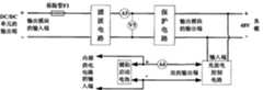
图1为本发明的整体结构原理框图。Fig. 1 is a block diagram of the overall structure of the present invention.
图2为本发明的燃料电池堆模块原理框图。Fig. 2 is a functional block diagram of the fuel cell stack module of the present invention.
图3为本发明的输出模块原理框图。Fig. 3 is a functional block diagram of the output module of the present invention.
图4为本发明的内部供电电路原理框图。Fig. 4 is a functional block diagram of the internal power supply circuit of the present invention.
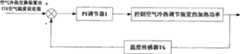
图5为本发明的PI调节器1快速启动时温度控制原理框图。Fig. 5 is a schematic block diagram of the temperature control when the
图6为本发明启动后燃料电池堆模块温度模糊控制原理框图。Fig. 6 is a schematic block diagram of the fuel cell stack module temperature fuzzy control after the start of the present invention.
图7为本发明的PI调节器2低温储存时温度控制原理框图。Fig. 7 is a block diagram of the temperature control principle of the
具体实施方式Detailed ways
下面结合附图及实施例对本发明作进一步的描述。The present invention will be further described below in conjunction with the accompanying drawings and embodiments.
本发明的主体部分由制氢储氢单元、燃料电池单元、DC/DC单元、输出单元、电控单元、巡检单元、监控单元以及通信单元组成(图1);制氢储氢单元利用太阳能或风能制氢并以固态存储,通过吸收燃料电池单元的热量释放氢气;燃料电池单元通过氢氧的电化学反应产生直流电能和热量;DC/DC单元对直流电能调节升压后给输出单元提供电能;输出单元在市电掉电时给负载供电;电控单元采集各种数据以及向各单元发送控制信息;巡检单元采集所有单片电压值进行传输;监控单元显示各种参数和状态,实现人机交互;通信单元进行近程和远程通信与监控。The main part of the present invention is composed of a hydrogen production and storage unit, a fuel cell unit, a DC/DC unit, an output unit, an electronic control unit, an inspection unit, a monitoring unit, and a communication unit (Fig. 1); the hydrogen production and storage unit utilizes solar energy Or wind energy produces hydrogen and stores it in a solid state, and releases hydrogen by absorbing the heat of the fuel cell unit; the fuel cell unit generates DC power and heat through the electrochemical reaction of hydrogen and oxygen; the DC/DC unit adjusts and boosts the DC power and provides it to the output unit Electric energy; the output unit supplies power to the load when the mains power fails; the electronic control unit collects various data and sends control information to each unit; the inspection unit collects all single-chip voltage values for transmission; the monitoring unit displays various parameters and status, Realize human-computer interaction; the communication unit performs short-range and long-range communication and monitoring.
制氢储氢单元由太阳能和风能制氢装置、高压固态储氢装置、高压电磁阀、手动减压阀、氢源氢气压力传感器P1以及固态储氢装置的空气出口温度传感器T7构成;制氢装置连接有氢源氢气压力传感器P1,利用太阳能或风能制氢,其氢气出口通过管道与固态储氢装置的氢气入口相连,氢气以固态形式储存在固态储氢装置中,固态储氢装置的氢气出口通过管道依次与高压电磁阀、手动减压阀和燃料电池单元中燃料电池堆模块的氢气入口相连,此外,固态储氢装置的空气入口经过温度传感器T6后与燃料电池单元中空气冷热交换装置的出口1相连,固态储氢装置的空气出口连接有温度传感器T7,然后通过管道接入大气,氢源氢气压力传感器P1和固态储氢装置的空气出口温度传感器T7的输出与电控单元的信号调理电路1的输入端相连,分别作为氢源氢气压力和固态储氢装置的空气出口温度的检测信号。The hydrogen production and storage unit is composed of a solar and wind energy hydrogen production device, a high-pressure solid-state hydrogen storage device, a high-pressure solenoid valve, a manual pressure reducing valve, a hydrogen source hydrogen pressure sensor P1, and an air outlet temperature sensor T7 of the solid-state hydrogen storage device; the hydrogen production device Connected with a hydrogen source hydrogen pressure sensor P1, using solar energy or wind energy to produce hydrogen, its hydrogen outlet is connected to the hydrogen inlet of the solid-state hydrogen storage device through a pipeline, the hydrogen is stored in the solid-state hydrogen storage device in solid form, and the hydrogen outlet of the solid-state hydrogen storage device The pipeline is connected with the high-pressure solenoid valve, the manual pressure reducing valve, and the hydrogen inlet of the fuel cell stack module in the fuel cell unit in sequence. In addition, the air inlet of the solid-state hydrogen storage device passes through the temperature sensor T6 and then communicates with the air cooling and heat exchange device in the fuel cell unit. The
燃料电池单元由氢气阀、调节阀、燃料电池堆模块、氢气分配器、尾气处理器、尾气阀、空气过滤器、空气加热装置、空气抽气装置、空气冷热交换装置、高压压力传感器P2、进堆氢气压力传感器P3、出堆氢气压力传感器P4、出堆空气温度传感器T5、空气冷热交换装置出口1的空气温度传感器T6、空气流量传感器Fa构成;在氢气供给回路中,来自制氢储氢单元的氢气通过管道与氢气阀的输入端相连,氢气阀的输出端通过管道依次与压力传感器P2、调节阀和分配器相连,电控单元通过控制氢气阀的开通和调压阀阀门的开度后,使氢气被进一步降压后进入氢气分配器,氢气分配器连接有进堆压力传感器P3,其输出端通过4根管道与燃料电池堆模块的氢气入口相连,使氢气由此进入燃料电池堆模块,燃料电池堆模块的氢气出口通过管道与尾气处理器的输入端相连,尾气处理器连接有出堆氢气压力传感器P4,通过燃烧对未反应完的氢气进行消耗处理,防止其泄露到室内或燃料电池单元内部与空气直接混合造成重大安全事故,其输出端通过管道与尾气阀的输入端相连,尾气阀的输出端通过管道接入大气,通过控制尾气阀的开通,排出部分尾气,保证燃料电池单元电化学反应的效率;在空气供给回路中(如图1黑色粗线所示),空气过滤器的风门与大气相连,其输出端通过管道与空气加热装置的输入端相连,通过控制风门的开度调节进入燃料电池单元内部的新鲜空气量,空气加热装置的输出端与燃料电池堆模块的空气入口连接,燃料电池堆模块的空气出口与空气抽气装置的输入端相连,通过控制空气抽气装置的转速产生压力差,使得空气从空气加热装置的输出端进入燃料电池堆模块进行反应,然后携带反应产生的热量从空气抽气装置的输出端流出,空气抽气装置的输出端通过管道依次与空气流量传感器Fa、出堆空气温度传感器T5和空气冷热交换装置的输入端相连,空气冷热交换装置的出口1通过管道依次与空气温度传感器T6和制氢储氢单元的固态储氢装置的空气入口相连,然后接入大气,空气冷热交换装置的出口2通过管道连接至燃料电池单元内部;燃料电池堆模块的正负极直流母线输出端电压为UO,与DC/DC单元的输入端相连;压力传感器P2~P4、温度传感器T5和T6、流量传感器Fa的输出与电控单元的信号调理电路1的输入端相连,分别作为高压氢气压力、进堆氢气压力和出堆氢气压力、出堆空气温度、空气冷热交换装置出口1的空气温度和空气流量的检测信号。The fuel cell unit consists of hydrogen valve, regulating valve, fuel cell stack module, hydrogen distributor, exhaust processor, exhaust valve, air filter, air heating device, air extraction device, air cooling and heat exchange device, high pressure pressure sensor P2, Incoming hydrogen pressure sensor P3, outgoing hydrogen pressure sensor P4, outgoing air temperature sensor T5, air temperature sensor T6 at
DC/DC单元由DC/DC1~4构成;DC/DC1~4的输入与输出端完全隔离,其额定输出功率分别为P1、P2、P3、P4,任意三者之和都大于负载功率和该系统自身消耗功率之和的最大值,DC/DC1~4的所有输入端并联作为DC/DC单元的直流电源总输入端,DC/DC1~4的输出端电压分别为UDC1、UDC2、UDC3、UDC4,并联后作为DC/DC单元的直流电源总输出端与输出单元的输入端相连,稳定工作时满足:UDC1=UDC2=UDC3=UDC4。当DC/DC1~4中任意一个出现故障时将其拔掉,使得余下3个DC/DC的输出仍然维持系统正常工作满足负载及该系统总功率消耗的需求,从而实现DC/DC单元“3+1”备份和热插拔功能。当燃料电池单元启动后给负载供电时,通过电控单元的D/A信号调节DC/DC1~4的输出电压,以方面使燃料电池堆各个模块的输出尽可能均匀和一致,另一方面,当辅助启动电池SOC值较低时,为其充电,从而提高系统的工作效率和使用寿命。The DC/DC unit is composed of DC/DC1~4; the input and output terminals of DC/DC1~4 are completely isolated, and their rated output powers are P1 , P2 , P3 , P4 respectively, and the sum of any three of them is greater than The maximum value of the sum of the load power and the system's own power consumption. All the input terminals of DC/DC1~4 are connected in parallel as the total input terminal of the DC power supply of the DC/DC unit. The output voltages of DC/DC1~4 are respectively UDC1 , UDC2 , UDC3 , and UDC4 are connected in parallel as the total output terminal of the DC power supply of the DC/DC unit and connected to the input terminal of the output unit, and the condition of stable operation is: UDC1 = UDC2 = UDC3 = UDC4 . When any one of DC/DC1~4 fails, unplug it, so that the output of the remaining 3 DC/DCs still maintains the normal operation of the system to meet the requirements of the load and the total power consumption of the system, thus realizing the DC/DC unit "3"+1" for backup and hotplug functionality. When the fuel cell unit starts to supply power to the load, the output voltage of DC/DC1~4 is adjusted through the D/A signal of the electronic control unit, so as to make the output of each module of the fuel cell stack as uniform and consistent as possible. On the other hand, When the SOC value of the auxiliary starting battery is low, it is charged, thereby improving the working efficiency and service life of the system.
输出单元由输出模块、内部供电电路、掉电检测电路构成;输出模块一端与负载相连,当市电供电正常时,由220V交流电整流为48V直流电给负载供电,同时对内部辅助启动电池进行充电;当市电掉电时,内部辅助启动电池给负载供电,同时与内部供电电路相连,内部供电电路输出24V的直流电压与空气抽气装置的供电端相连,输出12V的直流电压与高压阀、氢气阀、调节阀、尾气阀、负载开关1~4、空气加热装置、空气冷热交换装置以及DC/DC1~4的供电端相连为其供电,输出5V和3.3V的直流电压与温度传感器、电控单元、巡检单元、监控单元以及通信单元的供电端相连为其供电,还输出±12V的直流电压与各个电压、电流、压力和流量传感器的供电端相连为其供电;掉电检测电路含有市电电压检测传感器V6,其输出与电控单元的信号调理电路1的输入端相连,作为燃料电池单元快速启动或安全停机的检测信号。The output unit is composed of an output module, an internal power supply circuit, and a power failure detection circuit; one end of the output module is connected to the load. When the mains power supply is normal, the 220V AC is rectified into 48V DC to supply power to the load, and at the same time, the internal auxiliary starting battery is charged; When the mains power fails, the internal auxiliary starting battery supplies power to the load and is connected to the internal power supply circuit at the same time. The internal power
电控单元由信号调理电路1、A/D采样模块1、微处理器1(MCU1)、PWM输出模块、D/A输出模块、CAN1模块、I/O控制模块和驱动电路构成;信号调理电路1的输入端通过数据线与燃料电池堆1~4的输出电压传感器V1~V4、输出单元中的输出模块的输出总电压传感器V5、市电电压检测传感器V6、燃料电池堆1~4的输出电流传感器A1~A4、输出单元中的输出模块的输出总电流传感器温A5、辅助启动电池的充放电电流A6、燃料电池堆1~4的温度传感器T1~T4、出堆空气温度传感器T5、空气冷热交换装置出口1的空气温度传感器T6、制氢储氢单元的固态储氢装置的空气出口温度传感器T7、氢源氢气压力传感器P1、高压压力传感器P2、进堆氢气压力传感器P3、出堆氢气压力传感器P4以及空气流量传感器Fa的输出信号相连,信号调理电路1的输出端与A/D采样单元1相连,MCU1将各种传感器的模拟信号转换为数字信号进行计算处理;PWM输出模块与空气过滤器的风门、空气抽气装置以及调节阀的控制端相连,通过输出PWM信号控制空气过滤器的风门开度、空气抽气装置的转速和调节阀的输出压力;D/A输出模块与DC/DC 1~4的输出电压控制端相连,通过输出不同的数字量转换为模拟量信号控制DC/DC单元的输出电压值;驱动电路由I/O口控制,其输出端与高压阀、氢气阀、尾气处理器、尾气阀、空气加热装置、空气冷热交换装置、各个燃料电池堆的负载开关K1~K4、输出单元中的保护电路和充放电控制电路的功率开关管的控制端相连,控制其接通或关断;通过CAN1与巡检单元的CAN2、监控单元的CAN3和通信单元的CAN4相连并进行通信,发送控制命令以及接收来自巡检单元、监控单元和通信单元的相关数据和信息。The electronic control unit is composed of
巡检单元由信号调理电路2、A/D采样模块2、微控制器2(MCU2)、第二通讯模块2(RS232/485)、CAN2模块构成;信号调理电路2的输入端通过数据线与燃料电池堆模块所有单片电池正负端相连,信号调理电路2的输出端与A/D采样单元2相连;MCU2将所有单片电池电压值通过巡检单元的第二通讯模块2(RS232/485)发送到上位机,实现所有单片电池电压值在线监测,方便调试和维修;通过CAN2把重要有关单片电压值发送给电控单元供其调整控制参数和策略、发送给监控单元供其实时显示、发送给通信单元供其进行远程传输与监控。The inspection unit is composed of a
监控单元由LCD、微控制器3(MCU3)、声光报警及指示灯电路、按键、CAN3模块构成;通过CAN3与电控单元、巡检单元和通信单元通信;LCD与MCU3的数据总线和I/O口相连,通过翻屏、换页和滚动的方式实时显示制氢储氢单元、燃料电池单元、DC/DC单元、输出单元的各种参数与状态,以及电控单元、巡检单元和通信单元的命令字,此外还显示该系统的各种故障码(包括参数故障和工作状态故障);声光报警及指示灯电路对系统正常工作状态进行显示,在故障状态下进行声光报警;通过按下相应的按键,操作人员对该系统相关控制参数(如输出总电压、燃料电池堆1~4的温度、出堆空气温度、空气抽气装置的转速)进行设置以及对相关电压、电流、温度和压力等进行查看,或对其工作状态进行相应的操作和控制(如强制启动或关机、保温等)。The monitoring unit is composed of LCD, microcontroller 3 (MCU3), sound and light alarm and indicator circuit, buttons, and CAN3 module; it communicates with the electronic control unit, inspection unit and communication unit through CAN3; the data bus and I /O port connected, real-time display of various parameters and status of hydrogen production hydrogen storage unit, fuel cell unit, DC/DC unit, output unit, as well as electronic control unit, inspection unit and The command word of the communication unit, in addition, it also displays various fault codes of the system (including parameter faults and working state faults); the sound and light alarm and indicator light circuit display the normal working state of the system, and sound and light alarm in the fault state; By pressing the corresponding button, the operator sets the relevant control parameters of the system (such as the total output voltage, the temperature of
通信单元由微控制器4(MCU4)、GPRS模块、Ethernet模块、第一通讯模块1(RS232/485)和CAN4模块构成;通过CAN4与电控单元、巡检单元和监控单元通信;GPRS模块和Ethernet模块与MCU4的数据总线和I/O口相连,GPRS模块和远程监控中心进行无线通信,Ethernet模块与远程监控中心进行以太网或局域网相连实现有线通信;通讯接口之一采用RS232/485总线(通信单元的第一通讯模块1(RS232/485))与上位机通信,方便工作人员进行自动或手动调试与控制;另一通讯接口采用CAN总线(CAN4模块)与电控单元、巡检单元和监控单元通信,接收相关数据和信息,向其发送远程监控命令。The communication unit is composed of a microcontroller 4 (MCU4), a GPRS module, an Ethernet module, a first communication module 1 (RS232/485) and a CAN4 module; it communicates with an electronic control unit, an inspection unit and a monitoring unit through CAN4; the GPRS module and The Ethernet module is connected with the data bus and the I/O port of MCU4, the GPRS module communicates wirelessly with the remote monitoring center, and the Ethernet module connects with the remote monitoring center through Ethernet or LAN to realize wired communication; one of the communication interfaces adopts RS232/485 bus ( The first communication module 1 (RS232/485) of the communication unit communicates with the upper computer, which is convenient for the staff to carry out automatic or manual debugging and control; the other communication interface uses CAN bus (CAN4 module) to communicate with the electronic control unit, inspection unit and The monitoring unit communicates, receives relevant data and information, and sends remote monitoring commands to it.
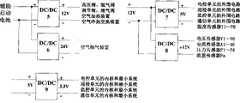
燃料电池堆模块(图2)由燃料电池堆1~4、进堆氢气热插拔接口I1~I4、出堆氢气热插拔接口01~04、燃料电池堆模块温度传感器T1~T4、燃料电池堆1~4的输出电压传感器V1~V4和输出电流传感器A1~A4、防反二极管D1~D4、负载开关K1~K4组成;燃料电池堆模块的氢气入口分别通过4根管道与进堆氢气热插拔接口I1~I4相连,然后分别与燃料电池堆1~4的氢气入口相连,燃料电池堆1~4的氢气出口分别通过管道与出堆氢气热插拔接口01~04相连,然后与燃料电池堆模块的氢气出口相连;燃料电池堆1~4的直流电源输出端分别为U1o、U2o、U3o、U4o,并分别串联有电流传感器A1~A4和并联有电压传感器V1~V4,各自的正极依次与防反二极管D1~D4和负载开关K1~K4相连,负载开关K1~K4的输出端并联后作为燃料电池单元的正负极直流电源母线输出端,在启动过程中,当控制负载开关K1~K4全部闭合后,燃料电池单元启动完成,此时输出电压满足U1o=U2o=U3o=U4o=Ufc,Ufc为燃料电池堆模块稳定输出总电压值;燃料电池堆1~4的额定输出功率分别为P1net、P2net、P3net、P4net,任意三者之和大于负载功率和该系统自身消耗功率之和的最大值,由于进堆氢气热插拔接口I1~I4和出堆氢气热插拔接口01~04在拔出时快速关闭以及对插时两端迅速连通的特性,当任意一个燃料电池堆出现故障时,将其拔掉进行更换或者维修,从而实现“3+1”备份和氢气气路热插拔功能,保证了系统的可靠性供电;温度传感器T1~T4分别嵌入燃料电池堆1~4中与单片电池相连,温度传感器T1~T4、电压传感器V1~V4和电流传感器A1~A4的输出与电控单元的信号调理电路1的输入端相连,MCU1将模拟信号转换为数字信号进行计算处理,分别作为燃料电池堆1~4的温度T1~T4、输出电压U1o~U4o和输出电流I1~I4的检测信号。The fuel cell stack module (Fig. 2) consists of fuel cell stacks 1-4, hydrogen hot-swappable interfaces I1-I4, hydrogen hot-swappable interfaces 01-04, fuel cell stack module temperature sensors T1-T4,
输出模块(图3)由保险管F1、滤波电路、保护电路、充放电控制电路、辅助启动电池、输出总电压传感器V5、输出总电流传感器A5和充放电电流传感器A6组成;输出模块的输入端串联有保险管F1,保险管F1的输出端与滤波电路的输入端相连,滤波电路对输入电压进行滤波,去除高频干扰将其调整为平滑的直流电压UDC,其输出端依次串联和并联有输出总电流传感器A5和输出总电压传感器V5,然后与保护电路的输入端相连;保护电路的输出端作为输出模块的输出端,一方面与负载相连,另一方面与充放电控制电路的输入端相连,当出现欠压、过压、过流、过热时通过关断内部功率开关管切断与负载和充放电控制电路的连接,实现对系统的保护;充放电控制电路的双向输出端与辅助启动电池的充放电电流传感器A6串联,然后与辅助启动电池的正负极相连;辅助启动电池的正负极还通过一个支路与内部供电电路相连;电压传感器V5、电流传感器A5和A6的输出与电控单元的信号调理电路1的输入端相连,分别作为该系统输出总电压、输出总电流以及辅助启动电池的充放电电流的检测信号。The output module (Fig. 3) is composed of fuse F1, filter circuit, protection circuit, charge and discharge control circuit, auxiliary starting battery, output total voltage sensor V5, output total current sensor A5 and charge and discharge current sensor A6; the input terminal of the output module A fuse F1 is connected in series, and the output terminal of the fuse F1 is connected to the input terminal of the filter circuit. The filter circuit filters the input voltage, removes high-frequency interference and adjusts it to a smooth DC voltage UDC , and its output terminals are connected in series and parallel in turn. There are output total current sensor A5 and output total voltage sensor V5, which are then connected to the input terminal of the protection circuit; the output terminal of the protection circuit is used as the output terminal of the output module, which is connected to the load on the one hand, and the input of the charge and discharge control circuit on the other hand When there is undervoltage, overvoltage, overcurrent, or overheating, the internal power switch tube is turned off to cut off the connection with the load and the charge and discharge control circuit, so as to realize the protection of the system; the bidirectional output terminal of the charge and discharge control circuit is connected to the auxiliary The charging and discharging current sensor A6 of the starting battery is connected in series, and then connected to the positive and negative poles of the auxiliary starting battery; the positive and negative poles of the auxiliary starting battery are also connected to the internal power supply circuit through a branch; the output of the voltage sensor V5, current sensors A5 and A6 It is connected with the input end of the
内部供电电路(图4)由DC/DC5~9组成;DC/DC5~9的输入端与输出端完全隔离,辅助启动电池的输出端与DC/DC5与DC/DC6的输入端相连,DC/DC5的输出端电压为12V,一方面与高压阀、氢气阀、调节阀、尾气阀、空气加热装置、空气冷热交换装置以及DC/DC1~4的供电端相连为其供电,另一方面与DC/DC7和DC/DC8的输入端相连实现电压进一步转换;DC/DC6的输出端电压为24V,与空气抽气装置的供电端相连为其供电;DC/DC7的输出端电压为5V,与电控单元、巡检单元、监控单元、通信单元的外围电路、温度传感器T1~T6的供电端相连为其供电,以及与DC/DC9的输入端相连实现电压进一步转换;DC/DC8的输出端电压为±12V,给电压传感器传感器V1~V6、电流传感器A1~A6、压力传感器P1~P4和流量传感器Fa供电;DC/DC9的输出端电压为3.3V,给电控单元、巡检单元、监控单元、通信单元的内核和最小系统供电。The internal power supply circuit (Figure 4) is composed of DC/DC5~9; the input terminals of DC/DC5~9 are completely isolated from the output terminals, the output terminals of the auxiliary starting battery are connected with the input terminals of DC/DC5 and DC/DC6, and the DC/DC5~9 are connected to the input terminals of DC/DC5 and DC/DC6. The output voltage of DC5 is 12V. On the one hand, it is connected to the high pressure valve, hydrogen valve, regulating valve, exhaust valve, air heating device, air cooling and heat exchange device and the power supply terminal of DC/DC1~4 to supply power. On the other hand, it is connected to the The input terminals of DC/DC7 and DC/DC8 are connected to realize further voltage conversion; the output terminal voltage of DC/DC6 is 24V, which is connected to the power supply terminal of the air suction device for power supply; the output terminal voltage of DC/DC7 is 5V, and The power supply terminals of the electronic control unit, inspection unit, monitoring unit, communication unit, and temperature sensors T1~T6 are connected to supply power for them, and connected to the input terminal of DC/DC9 to realize further voltage conversion; the output terminal of DC/DC8 The voltage is ±12V, which supplies power to the voltage sensors V1~V6, current sensors A1~A6, pressure sensors P1~P4 and flow sensor Fa; the output voltage of DC/DC9 is 3.3V, which supplies power to the electronic control unit, inspection unit, Core and minimum system power supply for supervisory unit, communication unit.
在本发明的实施例中,当检测市电掉电时,燃料电池单元快速智能启动,其过程分为以下几个步骤:In the embodiment of the present invention, when the mains power failure is detected, the fuel cell unit is quickly and intelligently started, and the process is divided into the following steps:
首先,为迅速获取氢气,电控单元将空气抽气装置调至最高的转速,关闭空气冷热交换装置的出口2同时打开其出口1,采用基于PI调节器的空气冷热交换装置出口1的空气温度控制(如图5所示),将空气冷热交换装置出口1的空气温度值设置为

其次,当空气冷热交换装置出口1的空气温度值上升到接近设置值T6′时,电控单元开通高压阀、氢气阀,并控制调节阀将氢气调到一定压力范围(通常为一个大气压左右),使其进入燃料电池堆模块参与反应,同时启动尾气处理器并开通尾气阀,在燃烧掉未反应完的氢气的同时通过排尾气使燃料电池堆模块气路畅通。Secondly, when the air temperature at the
然后,当燃料电池堆1~4输出电压均大于设定的最小安全启动电压值Umin(0.8*n,n为单片电池片数)时,电控单元控制负载开关K1~K4和充放电控制电路的充电开关闭合,同时控制放电开关断开并关闭尾气阀,然后输出D/A信号逐步提升DC/DC1~4的输出电压值,直至充放电电流传感器A6的输出值为负,此时燃料电池单元启动完成,一方面给负载供电,另一方面给辅助启动电池浮充直至充满。由于此时燃料电池堆模块温度较低,为使其温度保持在一定范围Tmin~Tmax,提高反应效率,通过检测输出电流IO,算出满足反应所需的2倍空气过量系数的空气流量值Fair,由空气流量Fair与空气抽气装置的转速Vair的对应关系(由实验获取)算出PWM信号的最小占空比Dmin,并通过PWM输出模块进行输出。Then, when the output voltages of
最后,燃料电池单元启动完成给负载及系统自身供电,当巡检单元发送过来的最低单片电压值Using_low低于设定值Using_min时,控制尾气阀每间隔m秒开通n秒排出部分尾气和生成的水,Using_low越低,设置m的值越小,反之越大。此时,燃料电池堆模块温度采用模糊控制(如图6所示),其具体实施为:将燃料电池堆模块的温度给定与温度传感器T1~T4比较得到误差和误差的变换率,通过模糊推理和去模糊化后,得到PWM信号的占空比,由PWM输出模块输出PWM信号控制空气抽气装置的转速实现风冷,若燃料电池堆1~4的温度T1~T4均低于Tmin时,使得输出PWM信号的占空比为Dmin(Dmin为控制空气抽气装置的最低转速保证空气过量系数为2时的最小占空比);若燃料电池堆1~4的温度T1~T4均高于Tmax时,使得输出PWM信号的占空比为1;若燃料电池堆1~4的温度T1~T4中,有i(1≤i≤3)个值高于Tmax时,使得输出PWM信号的占空比介于Dmin和1之间,i越大越接近1,反之越接近Dmin。Finally, the fuel cell unit starts to supply power to the load and the system itself. When the lowest single-chip voltage value Using_low sent by the inspection unit is lower than the set value Using_min , the exhaust gas valve is controlled to open every m seconds to discharge part of the exhaust gas for n seconds And the generated water, the lower Using_low is, the smaller the value of m is set, and vice versa. At this time, the temperature of the fuel cell stack module adopts fuzzy control (as shown in Figure 6). After reasoning and defuzzification, the duty cycle of the PWM signal is obtained, and the PWM signal is output by the PWM output module to control the speed of the air extraction device to achieve air cooling. If the temperatures T1 to
若在燃料电池单元工作过程中,当通过电压传感器V6的值检测市电供电正常时,电控单元通过依次断开负载开关K1~K4、开通尾气阀、关闭空气抽气装置、空气加热装置、空气冷热交换装置、氢气阀、调压阀和高压阀,从而实现安全关机使负载的供电重新转由市电提供。If during the working process of the fuel cell unit, when the value of the voltage sensor V6 detects that the mains power supply is normal, the electronic control unit sequentially disconnects the load switches K1~K4, opens the exhaust valve, closes the air suction device, the air heating device, Air cooling and heat exchange device, hydrogen valve, pressure regulating valve and high pressure valve, so as to realize safe shutdown and switch the power supply of the load to the mains again.
在本发明的实施例中,当环境温度低于0℃时,为实现低温储存将燃料电池单元的温度保持在


燃料电池单元由于市电长期正常供电而处于闲置状态不工作,会导致性能衰减,当检测其持续未工作时间超过设定值Tstop时,通过远程监控中心发送启动命令,或由现场操作人员按下启动按键,或由电控单元自动唤醒发送启动命令,强制启动燃料电池单元,启动过程如上所述几个步骤所示,此时控制负载开关K1~K4保持断开状态,尾气阀以定时间的方式排出尾气,通过这种空载运行生成的水保持质子交换膜的湿度,同时使燃料电池保持良好的电化学反应活性,从而提高了其使用寿命和长期储存能力。Due to the long-term normal power supply of the fuel cell unit, it is idle and does not work, which will lead to performance degradation. When it is detected that the continuous non-working time exceeds the set value Tstop , a start command is sent through the remote monitoring center, or the on-site operator presses Press the start button, or the electronic control unit automatically wakes up and sends a start command to forcibly start the fuel cell unit. The start process is shown in the above steps. At this time, the control load switches K1~K4 are kept in the off state, and the exhaust valve is set at a certain time. The exhaust gas is discharged in a way, and the water generated by this no-load operation maintains the humidity of the proton exchange membrane, and at the same time keeps the fuel cell with good electrochemical reactivity, thereby improving its service life and long-term storage capacity.
最后应说明,本发明的实施例仅用于说明技术方案而非限制。本发明说明书中未作详细描述的内容属于本专业领域技术人员公知的现有技术。Finally, it should be noted that the embodiments of the present invention are only used to illustrate the technical solutions rather than limit them. The contents not described in detail in the description of the present invention belong to the prior art known to those skilled in the art.
Claims (10)


Priority Applications (1)
| Application Number | Priority Date | Filing Date | Title |
|---|---|---|---|
| CN2009100610321ACN101505092B (en) | 2009-03-09 | 2009-03-09 | Standby electrical power system of fuel cell for communication |
Applications Claiming Priority (1)
| Application Number | Priority Date | Filing Date | Title |
|---|---|---|---|
| CN2009100610321ACN101505092B (en) | 2009-03-09 | 2009-03-09 | Standby electrical power system of fuel cell for communication |
Publications (2)
| Publication Number | Publication Date |
|---|---|
| CN101505092Atrue CN101505092A (en) | 2009-08-12 |
| CN101505092B CN101505092B (en) | 2011-11-16 |
Family
ID=40977221
Family Applications (1)
| Application Number | Title | Priority Date | Filing Date |
|---|---|---|---|
| CN2009100610321AExpired - Fee RelatedCN101505092B (en) | 2009-03-09 | 2009-03-09 | Standby electrical power system of fuel cell for communication |
Country Status (1)
| Country | Link |
|---|---|
| CN (1) | CN101505092B (en) |
Cited By (43)
| Publication number | Priority date | Publication date | Assignee | Title |
|---|---|---|---|---|
| CN101814768A (en)* | 2010-03-11 | 2010-08-25 | 昆山弗尔赛能源有限公司 | Fuel cell based standby power system |
| CN102013503A (en)* | 2010-11-04 | 2011-04-13 | 北京万瑞讯通科技有限公司 | Fuel cell standby power supply control system and control method thereof |
| CN102097636A (en)* | 2011-01-07 | 2011-06-15 | 武汉理工大学 | Fault diagnosis device and method of fuel cell system |
| CN102114789A (en)* | 2011-01-24 | 2011-07-06 | 昆山弗尔赛能源有限公司 | Multifunctional fuel-cell-driven automotive system |
| CN102361345A (en)* | 2011-10-21 | 2012-02-22 | 浙江大学 | Seamless switching control method for uninterrupted power supply of fuel cell |
| CN102386672A (en)* | 2011-11-23 | 2012-03-21 | 南京禾浩通信科技有限公司 | Standby power supply control system based on fuel cell |
| CN102569854A (en)* | 2012-01-30 | 2012-07-11 | 中国人民解放军63908部队 | Portable power supply system of proton exchange membrane fuel cell (PEMFC) |
| CN102594890A (en)* | 2012-02-17 | 2012-07-18 | 昆山弗尔赛能源有限公司 | Multifunctional remote monitoring system for fuel cell standby power supply |
| CN102904444A (en)* | 2012-08-07 | 2013-01-30 | 上海交通大学 | DC/DC Conversion and Control System Based on Proton Exchange Membrane Fuel Cell |
| CN103475066A (en)* | 2013-09-27 | 2013-12-25 | 瑞昌哥尔德发电设备(无锡)制造有限公司 | Uninterrupted power supply system |
| CN104201403A (en)* | 2014-08-13 | 2014-12-10 | 昆山弗尔赛能源有限公司 | Fuel cell backup power system |
| CN104393626A (en)* | 2014-07-16 | 2015-03-04 | 苏州华清京昆新能源科技有限公司 | Distributed solid oxide fuel cell charging station |
| CN104681829A (en)* | 2013-12-02 | 2015-06-03 | 陕西荣基实业有限公司 | Hydrogen fuel cell for communication base station |
| CN104836319A (en)* | 2015-05-26 | 2015-08-12 | 武汉众宇动力系统科技有限公司 | Integrated fuel cell power supply system |
| CN105024446A (en)* | 2015-07-02 | 2015-11-04 | 北京明德微纳技术发展有限公司 | Power supply method |
| CN106159299A (en)* | 2016-08-09 | 2016-11-23 | 江苏国泽光电科技有限公司 | A kind of method for controlling power supply of fuel cell system |
| CN106208370A (en)* | 2016-07-22 | 2016-12-07 | 安徽亚辉电气自动化有限公司 | A kind of monitor control system based on electric energy optimization device |
| CN106410947A (en)* | 2016-04-18 | 2017-02-15 | 北京航天动力研究所 | Commercial power refueling cell stand-by power supply apparatus |
| CN106787139A (en)* | 2016-12-27 | 2017-05-31 | 北京有色金属研究总院 | A kind of hydrogen-preparing hydrogen-storing backup power system of fuel cell for communication base station |
| CN107222154A (en)* | 2017-07-13 | 2017-09-29 | 天津中德应用技术大学 | Utilize the photovoltaic generating system and its control method of hydrogen fuel cell energy storage |
| CN107658930A (en)* | 2017-10-12 | 2018-02-02 | 东莞博力威新能源有限公司 | A kind of energy-storage battery |
| CN108598527A (en)* | 2018-05-17 | 2018-09-28 | 中车青岛四方机车车辆股份有限公司 | Fuel cell for pneumatic control method, device and system and rail vehicle |
| CN108767295A (en)* | 2018-04-19 | 2018-11-06 | 苏州诺登德智能科技有限公司 | A kind of Fuel Cell Control System |
| CN109193723A (en)* | 2018-10-11 | 2019-01-11 | 福建星云电子股份有限公司 | A kind of knockdown base station standby energy storage power and control method |
| CN109473704A (en)* | 2017-09-08 | 2019-03-15 | 徐煜 | Fuel cell system |
| CN110015206A (en)* | 2017-12-04 | 2019-07-16 | 中国科学院大连化学物理研究所 | A vehicle-mounted methanol fuel cell management system and method |
| CN110834568A (en)* | 2018-08-16 | 2020-02-25 | 深圳市佳华利道新技术开发有限公司 | Battery power supply system and control method thereof |
| CN111463469A (en)* | 2020-04-27 | 2020-07-28 | 浙江高成绿能科技有限公司 | Modular fuel cell standby power supply |
| CN111555435A (en)* | 2020-04-27 | 2020-08-18 | 珠海格力电器股份有限公司 | A power supply control device, a communication power supply system and a power supply control method thereof |
| CN111628197A (en)* | 2020-05-29 | 2020-09-04 | 湖北工业大学 | CAN bus-based fuel cell power system platform upper computer monitoring method |
| CN111682244A (en)* | 2017-11-08 | 2020-09-18 | 南京晓庄学院 | A control method of a reversible fuel cell stack energy-saving device |
| CN111725543A (en)* | 2020-06-30 | 2020-09-29 | 上海捷氢科技有限公司 | Hydrogen fuel cell and control method thereof |
| CN112359371A (en)* | 2020-10-12 | 2021-02-12 | 艾氢技术(苏州)有限公司 | Artificial intelligence integrated control system applied to solid magnesium hydride hydrolysis hydrogen generation power generation device |
| CN112467176A (en)* | 2020-12-04 | 2021-03-09 | 上海燃锐新能源汽车技术有限公司 | Hydrogen pressure control method and device for fuel cell engine system |
| CN112803566A (en)* | 2021-01-13 | 2021-05-14 | 中车青岛四方机车车辆股份有限公司 | Battery hybrid control device, power supply management system and rail vehicle |
| CN113113922A (en)* | 2021-04-08 | 2021-07-13 | 国网综合能源服务集团有限公司 | Comprehensive energy supply system |
| CN113299348A (en)* | 2021-05-24 | 2021-08-24 | 潍柴动力股份有限公司 | Uninterrupted power supply system and method |
| CN113612310A (en)* | 2021-08-09 | 2021-11-05 | 四川帝威能源技术有限公司 | System for converting hydrogen-oxygen reaction into electric energy |
| CN114844198A (en)* | 2022-04-19 | 2022-08-02 | 海南天宇科技集团有限公司 | Power architecture combining uninterruptible power system and solid hydrogen storage bottle |
| CN115117402A (en)* | 2022-08-26 | 2022-09-27 | 海卓动力(青岛)能源科技有限公司 | A fuel cell system unassisted starting system and starting method |
| CN115976571A (en)* | 2022-12-09 | 2023-04-18 | 北京奇稳新能源科技有限公司 | Hydrogen production control system with demand side response |
| CN117352777A (en)* | 2023-12-05 | 2024-01-05 | 大连擎研科技有限公司 | A fuel cell system and its low-temperature starting method |
| CN118782822A (en)* | 2024-07-09 | 2024-10-15 | 北京华清大运氢能科技有限公司 | A high-power metal bipolar plate fuel cell system and equipment |
Family Cites Families (3)
| Publication number | Priority date | Publication date | Assignee | Title |
|---|---|---|---|---|
| JP2003197231A (en)* | 2001-12-26 | 2003-07-11 | Toyota Motor Corp | Fuel cell power generation system and control method thereof |
| CN1632978A (en)* | 2004-12-29 | 2005-06-29 | 武汉理工大学 | A control method and device for a vehicle fuel cell engine |
| CN2914100Y (en)* | 2006-01-25 | 2007-06-20 | 武汉理工大学 | Monolithic voltage detector of fuel battery group |
- 2009
- 2009-03-09CNCN2009100610321Apatent/CN101505092B/ennot_activeExpired - Fee Related
Cited By (57)
| Publication number | Priority date | Publication date | Assignee | Title |
|---|---|---|---|---|
| CN101814768A (en)* | 2010-03-11 | 2010-08-25 | 昆山弗尔赛能源有限公司 | Fuel cell based standby power system |
| CN102013503A (en)* | 2010-11-04 | 2011-04-13 | 北京万瑞讯通科技有限公司 | Fuel cell standby power supply control system and control method thereof |
| CN102013503B (en)* | 2010-11-04 | 2012-09-05 | 北京万瑞讯通科技有限公司 | Fuel cell standby power supply control system and control method thereof |
| CN102097636A (en)* | 2011-01-07 | 2011-06-15 | 武汉理工大学 | Fault diagnosis device and method of fuel cell system |
| CN102097636B (en)* | 2011-01-07 | 2013-07-17 | 武汉理工大学 | Fault diagnosis device and method of fuel cell system |
| CN102114789A (en)* | 2011-01-24 | 2011-07-06 | 昆山弗尔赛能源有限公司 | Multifunctional fuel-cell-driven automotive system |
| CN102361345A (en)* | 2011-10-21 | 2012-02-22 | 浙江大学 | Seamless switching control method for uninterrupted power supply of fuel cell |
| CN102386672A (en)* | 2011-11-23 | 2012-03-21 | 南京禾浩通信科技有限公司 | Standby power supply control system based on fuel cell |
| CN102569854B (en)* | 2012-01-30 | 2014-07-09 | 中国人民解放军63908部队 | Portable power supply system of proton exchange membrane fuel cell (PEMFC) |
| CN102569854A (en)* | 2012-01-30 | 2012-07-11 | 中国人民解放军63908部队 | Portable power supply system of proton exchange membrane fuel cell (PEMFC) |
| CN102594890A (en)* | 2012-02-17 | 2012-07-18 | 昆山弗尔赛能源有限公司 | Multifunctional remote monitoring system for fuel cell standby power supply |
| CN102904444B (en)* | 2012-08-07 | 2015-01-21 | 上海交通大学 | DC/DC Conversion and Control System Based on Proton Exchange Membrane Fuel Cell |
| CN102904444A (en)* | 2012-08-07 | 2013-01-30 | 上海交通大学 | DC/DC Conversion and Control System Based on Proton Exchange Membrane Fuel Cell |
| CN103475066A (en)* | 2013-09-27 | 2013-12-25 | 瑞昌哥尔德发电设备(无锡)制造有限公司 | Uninterrupted power supply system |
| CN104681829A (en)* | 2013-12-02 | 2015-06-03 | 陕西荣基实业有限公司 | Hydrogen fuel cell for communication base station |
| CN104393626A (en)* | 2014-07-16 | 2015-03-04 | 苏州华清京昆新能源科技有限公司 | Distributed solid oxide fuel cell charging station |
| CN104201403A (en)* | 2014-08-13 | 2014-12-10 | 昆山弗尔赛能源有限公司 | Fuel cell backup power system |
| CN104836319A (en)* | 2015-05-26 | 2015-08-12 | 武汉众宇动力系统科技有限公司 | Integrated fuel cell power supply system |
| CN105024446A (en)* | 2015-07-02 | 2015-11-04 | 北京明德微纳技术发展有限公司 | Power supply method |
| CN106410947A (en)* | 2016-04-18 | 2017-02-15 | 北京航天动力研究所 | Commercial power refueling cell stand-by power supply apparatus |
| CN106208370A (en)* | 2016-07-22 | 2016-12-07 | 安徽亚辉电气自动化有限公司 | A kind of monitor control system based on electric energy optimization device |
| CN106159299A (en)* | 2016-08-09 | 2016-11-23 | 江苏国泽光电科技有限公司 | A kind of method for controlling power supply of fuel cell system |
| CN106787139A (en)* | 2016-12-27 | 2017-05-31 | 北京有色金属研究总院 | A kind of hydrogen-preparing hydrogen-storing backup power system of fuel cell for communication base station |
| CN107222154A (en)* | 2017-07-13 | 2017-09-29 | 天津中德应用技术大学 | Utilize the photovoltaic generating system and its control method of hydrogen fuel cell energy storage |
| CN107222154B (en)* | 2017-07-13 | 2023-09-12 | 天津中德应用技术大学 | Photovoltaic power generation system utilizing hydrogen fuel cell to store energy and control method thereof |
| CN109473704A (en)* | 2017-09-08 | 2019-03-15 | 徐煜 | Fuel cell system |
| CN107658930A (en)* | 2017-10-12 | 2018-02-02 | 东莞博力威新能源有限公司 | A kind of energy-storage battery |
| CN111682244B (en)* | 2017-11-08 | 2022-04-29 | 南京晓庄学院 | Control method of energy-saving device of reversible fuel cell stack |
| CN111682244A (en)* | 2017-11-08 | 2020-09-18 | 南京晓庄学院 | A control method of a reversible fuel cell stack energy-saving device |
| CN110015206A (en)* | 2017-12-04 | 2019-07-16 | 中国科学院大连化学物理研究所 | A vehicle-mounted methanol fuel cell management system and method |
| CN108767295A (en)* | 2018-04-19 | 2018-11-06 | 苏州诺登德智能科技有限公司 | A kind of Fuel Cell Control System |
| CN108598527B (en)* | 2018-05-17 | 2020-08-14 | 中车青岛四方机车车辆股份有限公司 | Gas supply control method, device and system for fuel cell, and rail vehicle |
| CN108598527A (en)* | 2018-05-17 | 2018-09-28 | 中车青岛四方机车车辆股份有限公司 | Fuel cell for pneumatic control method, device and system and rail vehicle |
| CN110834568A (en)* | 2018-08-16 | 2020-02-25 | 深圳市佳华利道新技术开发有限公司 | Battery power supply system and control method thereof |
| CN110834568B (en)* | 2018-08-16 | 2023-04-07 | 深圳市佳华利道新技术开发有限公司 | Battery power supply system and control method thereof |
| CN109193723A (en)* | 2018-10-11 | 2019-01-11 | 福建星云电子股份有限公司 | A kind of knockdown base station standby energy storage power and control method |
| CN109193723B (en)* | 2018-10-11 | 2023-12-05 | 福建星云电子股份有限公司 | Combined base station backup energy storage power supply and control method |
| CN111463469A (en)* | 2020-04-27 | 2020-07-28 | 浙江高成绿能科技有限公司 | Modular fuel cell standby power supply |
| CN111555435A (en)* | 2020-04-27 | 2020-08-18 | 珠海格力电器股份有限公司 | A power supply control device, a communication power supply system and a power supply control method thereof |
| CN111628197A (en)* | 2020-05-29 | 2020-09-04 | 湖北工业大学 | CAN bus-based fuel cell power system platform upper computer monitoring method |
| CN111725543A (en)* | 2020-06-30 | 2020-09-29 | 上海捷氢科技有限公司 | Hydrogen fuel cell and control method thereof |
| CN111725543B (en)* | 2020-06-30 | 2021-09-24 | 上海捷氢科技有限公司 | Hydrogen fuel cell and control method thereof |
| CN112359371A (en)* | 2020-10-12 | 2021-02-12 | 艾氢技术(苏州)有限公司 | Artificial intelligence integrated control system applied to solid magnesium hydride hydrolysis hydrogen generation power generation device |
| CN112359371B (en)* | 2020-10-12 | 2023-11-17 | 艾氢技术(苏州)有限公司 | An artificial intelligence comprehensive control system applied to solid magnesium hydride hydrolysis hydrogen generation power generation device |
| CN112467176A (en)* | 2020-12-04 | 2021-03-09 | 上海燃锐新能源汽车技术有限公司 | Hydrogen pressure control method and device for fuel cell engine system |
| CN112803566A (en)* | 2021-01-13 | 2021-05-14 | 中车青岛四方机车车辆股份有限公司 | Battery hybrid control device, power supply management system and rail vehicle |
| CN113113922A (en)* | 2021-04-08 | 2021-07-13 | 国网综合能源服务集团有限公司 | Comprehensive energy supply system |
| CN113299348A (en)* | 2021-05-24 | 2021-08-24 | 潍柴动力股份有限公司 | Uninterrupted power supply system and method |
| CN113299348B (en)* | 2021-05-24 | 2023-01-06 | 潍柴动力股份有限公司 | Uninterrupted power supply system and method |
| CN113612310A (en)* | 2021-08-09 | 2021-11-05 | 四川帝威能源技术有限公司 | System for converting hydrogen-oxygen reaction into electric energy |
| CN113612310B (en)* | 2021-08-09 | 2023-06-20 | 四川帝威能源技术有限公司 | System for converting oxyhydrogen reaction into electric energy |
| CN114844198A (en)* | 2022-04-19 | 2022-08-02 | 海南天宇科技集团有限公司 | Power architecture combining uninterruptible power system and solid hydrogen storage bottle |
| CN115117402A (en)* | 2022-08-26 | 2022-09-27 | 海卓动力(青岛)能源科技有限公司 | A fuel cell system unassisted starting system and starting method |
| CN115976571A (en)* | 2022-12-09 | 2023-04-18 | 北京奇稳新能源科技有限公司 | Hydrogen production control system with demand side response |
| CN117352777A (en)* | 2023-12-05 | 2024-01-05 | 大连擎研科技有限公司 | A fuel cell system and its low-temperature starting method |
| CN117352777B (en)* | 2023-12-05 | 2024-03-05 | 大连擎研科技有限公司 | Fuel cell system and low-temperature starting method thereof |
| CN118782822A (en)* | 2024-07-09 | 2024-10-15 | 北京华清大运氢能科技有限公司 | A high-power metal bipolar plate fuel cell system and equipment |
Also Published As
| Publication number | Publication date |
|---|---|
| CN101505092B (en) | 2011-11-16 |
Similar Documents
| Publication | Publication Date | Title |
|---|---|---|
| CN101505092B (en) | Standby electrical power system of fuel cell for communication | |
| CN201466785U (en) | A fuel cell backup power supply device for communication | |
| CN102569854B (en) | Portable power supply system of proton exchange membrane fuel cell (PEMFC) | |
| CN111564647B (en) | Power supply system of methanol water hydrogen fuel cell and control method thereof | |
| CN106787139A (en) | A kind of hydrogen-preparing hydrogen-storing backup power system of fuel cell for communication base station | |
| CN108332060B (en) | Intelligent monitoring system for pipeline water leakage | |
| CN114374220A (en) | An electrochemical cell-hydrogen production by electrolysis of water-hydrogen storage-hydrogen fuel cell coupled energy storage system and control method | |
| CN103078362A (en) | Backup power system based on fuel cell for communication | |
| CN203617394U (en) | Portable PEMFC (proton exchange membrane fuel cell) power supply system | |
| CN101814768A (en) | Fuel cell based standby power system | |
| CN103579651A (en) | Portable proton-exchange membrane fuel cell power system | |
| CN101625558A (en) | Field emergency renewable energy source management system and implementing method thereof | |
| US12438166B2 (en) | Large proton exchange membrane fuel cell power station process system | |
| CN103248082A (en) | Fuel cell standby power supply system provided with hydrogen circulation device | |
| CN106981929A (en) | A kind of energy-conserving and environment-protective wireless remote monitoring system of electric substation communicated based on GPRS | |
| CN113193645B (en) | Control method of hydrogen fuel cell emergency power supply system | |
| CN111082413A (en) | An urban community full DC microgrid and its control system | |
| CN203406664U (en) | Micro-grid distributed new energy storage device | |
| CN202026127U (en) | Integrated fuel battery backup power supply system for on-site hydrogen production | |
| CN201821261U (en) | A backup power system based on fuel cell | |
| CN216308059U (en) | Combined cooling, heating and power system for building based on proton exchange membrane fuel cell | |
| CN110061566A (en) | Internet of Things low-voltage platform area distribution transforming intelligent Circuit Breaker Controller | |
| CN219678186U (en) | Uninterruptible power supply based on asymmetric half-bridge flyback converter | |
| CN110762396A (en) | Intelligent gas pressure regulating box | |
| CN207765545U (en) | A kind of backup type hydrogen-fueled system |
Legal Events
| Date | Code | Title | Description |
|---|---|---|---|
| C06 | Publication | ||
| PB01 | Publication | ||
| C10 | Entry into substantive examination | ||
| SE01 | Entry into force of request for substantive examination | ||
| C14 | Grant of patent or utility model | ||
| GR01 | Patent grant | ||
| TR01 | Transfer of patent right | Effective date of registration:20180207 Address after:430074 Hubei city of Wuhan province East Lake New Technology Development Zone Wu Da Yuan Road four building a layer of 120-B research Patentee after:Amperex Technology Limited of the Wuhan sea Address before:430070 Hubei city of Wuhan province Wuchang Luoshi Road No. 122 Patentee before:Wuhan University of Technology | |
| TR01 | Transfer of patent right | ||
| CF01 | Termination of patent right due to non-payment of annual fee | Granted publication date:20111116 Termination date:20210309 | |
| CF01 | Termination of patent right due to non-payment of annual fee |