CN101501544B - Reinforced Fiber Optic Connector Assemblies - Google Patents
Reinforced Fiber Optic Connector AssembliesDownload PDFInfo
- Publication number
- CN101501544B CN101501544BCN200780030232XACN200780030232ACN101501544BCN 101501544 BCN101501544 BCN 101501544BCN 200780030232X ACN200780030232X ACN 200780030232XACN 200780030232 ACN200780030232 ACN 200780030232ACN 101501544 BCN101501544 BCN 101501544B
- Authority
- CN
- China
- Prior art keywords
- fiber optic
- connector assembly
- reinforced fiber
- optic connector
- plug housing
- Prior art date
- Legal status (The legal status is an assumption and is not a legal conclusion. Google has not performed a legal analysis and makes no representation as to the accuracy of the status listed.)
- Expired - Fee Related
Links
Images


Classifications
- G—PHYSICS
- G02—OPTICS
- G02B—OPTICAL ELEMENTS, SYSTEMS OR APPARATUS
- G02B6/00—Light guides; Structural details of arrangements comprising light guides and other optical elements, e.g. couplings
- G02B6/24—Coupling light guides
- G02B6/36—Mechanical coupling means
- G02B6/38—Mechanical coupling means having fibre to fibre mating means
- G02B6/3807—Dismountable connectors, i.e. comprising plugs
- G02B6/3869—Mounting ferrules to connector body, i.e. plugs
- G—PHYSICS
- G02—OPTICS
- G02B—OPTICAL ELEMENTS, SYSTEMS OR APPARATUS
- G02B6/00—Light guides; Structural details of arrangements comprising light guides and other optical elements, e.g. couplings
- G02B6/24—Coupling light guides
- G02B6/36—Mechanical coupling means
- G02B6/38—Mechanical coupling means having fibre to fibre mating means
- G02B6/3807—Dismountable connectors, i.e. comprising plugs
- G02B6/3887—Anchoring optical cables to connector housings, e.g. strain relief features
- G02B6/3889—Anchoring optical cables to connector housings, e.g. strain relief features using encapsulation for protection, e.g. adhesive, molding or casting resin
Landscapes
- Physics & Mathematics (AREA)
- General Physics & Mathematics (AREA)
- Optics & Photonics (AREA)
- Mechanical Coupling Of Light Guides (AREA)
Abstract
Description
Translated fromChinese技术领域technical field
本发明一般涉及一种加强的(ruggedized)光纤连接器组件,也称为光纤“插头”。更具体地说,本发明涉及一种包括保持主体(retention body)或胶主体的加强的光纤连接器组件,其被配置成用以保持优选具有一个或多个强力构件的光纤缆线,并且啮合光纤插座或者可替换地啮合另一个光纤连接器组件。The present invention generally relates to a ruggedized fiber optic connector assembly, also known as a fiber optic "plug." More specifically, the present invention relates to a reinforced fiber optic connector assembly including a retention body or adhesive body configured to retain a fiber optic cable, preferably having one or more strength members, and to engage The fiber optic receptacle alternatively engages another fiber optic connector assembly.
背景技术Background technique
光纤正越来越多地被用于包括声音、视频和数据传输的各种宽带应用。因此,光纤通信网络包括多个互连点,多根光纤在互连点处被互相连接。光纤通信网络又包括多个连接终端,其例子包括但不限于网络接入点(NAP)机柜、架空接线盒、地下接线盒、基座、光网络终端(ONTs)、网络接口设备(NIDs)和多端口设备。在某些情况下,连接终端包括通常经由连接终端的外壁打开的连接器端口,它们通常被用来在从分配缆线端接的光纤与一条或多条统称为“引入缆线(drop clables)”的预先连接器化(pre-connectorized)的引入缆线、扩展的分配缆线、系绳缆线(tether cables)或分支缆线的各个光纤之间建立光学连接。连接终端被用于将光纤通信服务便捷地延伸到用户。在这方面,正开发用于提供“光纤到路边”(FTTC)、“光纤到楼”(FTTB)、“光纤到户”(FTTH)、和“光纤到驻地”(FTTP)的光纤通信网络,这些一般称为“FTTx”。Fiber optics are increasingly being used for a variety of broadband applications including voice, video and data transmission. Accordingly, a fiber optic communication network includes a plurality of interconnection points at which a plurality of optical fibers are interconnected. Fiber optic communication networks in turn include multiple connection terminals, examples of which include, but are not limited to, network access point (NAP) cabinets, overhead junction boxes, underground junction boxes, pedestals, optical network terminals (ONTs), network interface devices (NIDs) and multi-port device. In some cases, the connection terminal includes a connector port, usually opened through the outer wall of the connection terminal, which is usually used to connect the optical fiber terminated from the distribution cable with one or more cables collectively referred to as "drop clables". Establish optical connections between the individual fibers of pre-connectorized drop cables, extended distribution cables, tether cables, or branch cables. Connection terminals are used to conveniently extend fiber optic communication services to users. In this regard, fiber optic communication networks are being developed to provide "Fiber to the Curb" (FTTC), "Fiber to the Building" (FTTB), "Fiber to the Home" (FTTH), and "Fiber to the Premises" (FTTP) , these are generally referred to as "FTTx".
经由连接终端的外壁打开的传统连接器端口通常包括一插座,该插座配置成用以接收该终端内侧上的连接器化的光纤和该终端外侧上的连接器化的引入缆线。配合套管(ferrule)中的一个配合套管被装配到一光纤的端部上,该光纤被光互连到连接终端内分配缆线的至少一根光纤。另一配合套管被装配到引入缆线的光纤的端部,该缆线从连接终端的外部插入插座。插座的对准套筒通常协助套管对准,并且套管导销(guide pin)或其它对准装置可以进一步协助多光纤套管的精确对准。Conventional connector ports that open through the outer wall of a connection terminal typically include a receptacle configured to receive a connectorized optical fiber on the inside of the terminal and a connectorized drop cable on the outside of the terminal. One of the mating ferrules is fitted onto the end of an optical fiber optically interconnected to at least one optical fiber of the distribution cable within the connection terminal. Another mating sleeve is fitted to the end of the optical fiber of the incoming cable which is inserted into the receptacle from the outside of the connection terminal. The alignment sleeve of the receptacle typically assists in ferrule alignment, and ferrule guide pins or other alignment devices may further assist in precise alignment of the multi-fiber ferrule.
特别地,装配在引入缆线端部上的插头与相应插座的一侧啮合。通常,插头包括光纤连接器和大致圆柱形的插头主体,该光纤连接器包括设置在该插头主体内的插头套管。插头主体的端部是打开的,或者设有一个或多个开口,以便套管在插头主体内是可达到的(accesible),例如用以进行清洁。套管被装配到引入缆线的一根或多根光纤的端部,以便对插头与插座进行的配合使得引入缆线的光纤与从连接终端内的分配缆线端接的各个光纤对准。在插头与插座的配合处理中,套管被插入容纳在插座内的对准套筒的一端。由于传统插头的这种构造,导致当套管被插入对准套筒时,对准套筒被最小地接纳在插头主体的打开端部内。作为对以上的一种替换,装配在引入缆线端部上的插头与装配在另一引入缆线的端部上的插头啮合,或者啮合与一连接终端不相联系的另一插座,该连接终端例如与商业场所、家庭、驻地等等相联系。In particular, a plug fitted on the end of the lead-in cable engages with one side of the corresponding socket. Typically, a plug includes a fiber optic connector including a plug ferrule disposed within the plug body and a generally cylindrical plug body. The end of the plug body is open, or provided with one or more openings, so that the sleeve is accessible within the plug body, eg for cleaning. A ferrule is fitted to the end of one or more optical fibers of the drop cable such that mating of the plug and receptacle aligns the optical fibers of the drop cable with the respective optical fibers terminated from the distribution cable within the connection terminal. During mating of the plug with the receptacle, the ferrule is inserted into one end of an alignment sleeve received within the receptacle. Due to this configuration of conventional plugs, the alignment sleeve is minimally received within the open end of the plug body when the ferrule is inserted into the alignment sleeve. As an alternative to the above, a plug fitted on the end of the incoming cable engages a plug fitted on the end of another incoming cable, or another socket not associated with a connection terminal, the connection Terminals are associated, for example, with businesses, homes, residences, and the like.
已经开发出了几种不同类型的传统连接器,其例子包括但不限于SC、ST、LC、MTP、MT-RJ和SC-DC。这些连接器中的每一种连接器的套管的尺寸和形状都有些不同。相应地,插头主体和对准套筒的尺寸和形状也有些不同。结果,在传统的实践中,不同的插头和插座与不同的套管一起使用。在这方面,插座一般限定与不同大小的对准套筒和插头主体相对应的不同大小的内腔和特征,这又限定设置在这些插头主体和对准套筒内的不同套管。Several different types of conventional connectors have been developed, examples of which include, but are not limited to, SC, ST, LC, MTP, MT-RJ, and SC-DC. The size and shape of the ferrule for each of these connectors is somewhat different. Correspondingly, the size and shape of the plug body and alignment sleeve are somewhat different. As a result, different plugs and sockets are used with different bushings in conventional practice. In this regard, receptacles generally define differently sized lumens and features corresponding to differently sized alignment sleeves and plug bodies, which in turn define different sleeves disposed within these plug bodies and alignment sleeves.
参照现有技术图1,传统的连接器10包括插头外壳12,在该插头外壳12中,压接(crimp)带16和包括两个一半部分14a、14b的压接主体14在组装期间被轴向设置。如下面更详细地描述的那样,还使用热缩件18。总起来说,压接主体14和压接带16保持引入缆线20和连接器子组件22(即,预组装的套管支持器模块)二者,该连接器子组件22支持套管24。特别地,连接器子组件22的轴25被固定在压接主体14的两个一半部分14a、14b之间。由此,套管24和引入缆线20的光纤被光学连接。热缩件18设置在引入缆线20的端部与插头外壳12的端部周围,从而提供一些保持力和应力消除,以及柔性的环境密封。如图所示,引入缆线20是单光纤引入缆线并且套管24是单端接套管,尽管其它类型的引入缆线、光纤和套管也可以与其它类型的连接器一起使用。这种内部组件被部分地容纳在连接螺母26内,连接螺母26是外螺纹的,以使连接器10被配置成用以与插座(未示出)的对准套筒的内螺纹啮合,从而对准并光学配合连接器10的套管24和插座的套管。如上所述,导销或者其它对准装置可以协助多光纤套管的更精确对准。例如,对准套筒和/或插座和插头外壳12的末端可以是有键的(keyed)。连接器10又包括一个或多个硅树脂O形环28和尾套(boot)30,当接合时,硅树脂O形环28对连接器10和插座进行环境密封,尾套30进一步消除引入缆线20中的应力。最后,连接器10包括一个或多个防尘盖34、32,它们被用以选择性地保护插头外壳12的暴露端和套管24。优选地,也称为“拉盖(pulling cap)”的防尘盖34的大部分是内螺纹的,以使其配置成用以啮合连接螺母26的外螺纹。最后,拉盖34经塑料牵索(lanyard)36或其它保持装置被固定到尾套20,以使拉盖34不易丢失。连接器10为厂外(outside plant)配置提供变坚固的连接器并包括为拉力而设计的整体拉孔(pulling eye)38。1, a
然而,至今仍有对一种可替换的(或另外的)保持方法的未解决的需求,该方法用于处理其它不可兼容引入缆线强力构件,这些不可兼容引入缆线强力构件诸如是玻璃增强塑料(GRP)强力构件等等。在端接期间,上述压接主体14的两个一半部分14a、14b的操作和配合经常施加过多的应力并危及光纤(其通常具有大约250μm的直径)。此外,这种压接设计独自通常并不强得足以满足拉力要求,从而迫使需要使用粘合剂。这种粘合剂坚硬地固定连接器子组件,消除了补偿因制造公差而导致产生的径向偏移的能力。这种径向偏移能够通过使适配器“浮动(floating)”而被补偿,但是,在插头对插头(plug-to-plug)布置方式中,没有这种浮动元件。因此,制造公差变得更加严格苛刻。更进一步,这种结合热缩件18的压接设计依赖于插头外壳12抵靠连接螺母26的硬止挡(hard stop),并最终依赖于热缩件18本身,以在处理和使用过程中将引入缆线20和连接器子组件22保持在同一位置。在高温环境下,并且由于热缩件18的应用期间不适当固定的缘故,使得插头外壳12能轴向移动并且活塞作用(piston)于适当位置或不适当位置。至今,还有对一种可替换的保持方法的未解决的需求,该方法不允许多方向(multiple ways)(即,两个180度的相反方向)组装连接器部件,从而要求由操作者固定和确认以便确保连接器子组件22被适当取向。有时,当端面角的取向不可兼容时,这需要切断好的连接器,导致产生废料。However, there remains as yet an unresolved need for an alternative (or additional) retention method for dealing with otherwise incompatible drop cable strength members such as glass reinforced Plastic (GRP) strength members and more. During termination, the handling and mating of the two halves 14a, 14b of the
发明内容Contents of the invention
在本发明的一实施例中,加强的光纤连接器组件包括:基本中空的插头外壳;和设置在基本中空的插头外壳内的保持主体;其中保持主体包括配置成用以啮合并保持包含光纤和一个或多个强力构件的光缆的第一部分;其中所述保持主体限定一个或多个边缘沟道,所述边缘沟道被配置成用以接收所述一个或多个强力构件;其中保持主体包括配置成用以啮合并保持包含光学套管的连接器子组件的第二部分,所述第二部分包括一对相对的安全钩,所述安全钩被配置成用以啮合连接器子组件的相应的一对相对的凹槽;以及其中光纤和光学套管被光学耦合。In one embodiment of the present invention, a reinforced fiber optic connector assembly includes: a substantially hollow plug housing; and a retention body disposed within the substantially hollow plug housing; A first portion of an optical cable of one or more strength members; wherein the retention body defines one or more edge channels configured to receive the one or more strength members; wherein the retention body includes Configured to engage and retain a second portion of a connector subassembly that includes an optical ferrule, the second portion includes a pair of opposing snap hooks configured to engage corresponding ones of the connector subassembly a pair of opposing grooves; and wherein the optical fiber and the optical ferrule are optically coupled.
在本发明的另一实施例中,加强的光纤连接器组件包括:基本中空的插头外壳;和设置在基本中空的插头外壳内的保持主体;其中保持主体包括配置成用以啮合并保持包含光纤和一个或多个强力构件的光缆的第一部分;其中保持主体包括配置成用以啮合并保持包含光学套管的连接器子组件的第二部分;其中保持主体的第二部分包括配置成用以与连接器子组件的相应的一对相对的凹槽啮合的一对相对的安全钩(snap hooks);以及其中光纤和光学套管被光学耦合。In another embodiment of the present invention, a reinforced fiber optic connector assembly includes: a substantially hollow plug housing; and a retention body disposed within the substantially hollow plug housing; and one or more strength members; wherein the retaining body includes a second portion configured to engage and retain a connector subassembly comprising an optical ferrule; wherein the second portion of the retaining body includes a second portion configured to a pair of opposing snap hooks engaging a corresponding pair of opposing grooves of the connector subassembly; and wherein the optical fiber and the optical ferrule are optically coupled.
在本发明的进一步的实施例中,加强的光纤连接器组件包括:基本中空的插头外壳;和设置在基本中空的插头外壳内的胶主体;其中胶主体包括配置成用以啮合并保持包含光纤和一个或多个强力构件的光缆的第一部分;其中胶主体包括配置成用以啮合并保持包含光学套管的连接器子组件的第二部分;其中胶主体的第二部分包括配置成用以与连接器子组件的相应的一对相对的凹槽啮合的一对相对的安全钩;以及其中光纤和光学套管被光学耦合。In a further embodiment of the present invention, a reinforced fiber optic connector assembly includes: a substantially hollow plug housing; and an adhesive body disposed within the substantially hollow plug housing; and one or more strength members; wherein the adhesive body includes a second portion configured to engage and retain a connector subassembly that includes an optical ferrule; wherein the second portion of the adhesive body includes a second portion configured to a pair of opposing snap hooks engaging a corresponding pair of opposing grooves of the connector subassembly; and wherein the optical fiber and the optical ferrule are optically coupled.
本发明的另外的特征和优点将在下面解释其原理和操作的详细描述中提出,并且对于本领域普通技术人员来说,根据该描述,这些特征和优点将是显而易见的,和/或是通过实践如所描述的那样的本发明而认识到的。应当理解,上述一般描述以及下面的详细描述呈现了本发明的示范性实施例,这些实施例打算用来提供用于理解如所要求保护的本发明的本质和特征的概述和框架。附图包括在说明书中并构成说明书的一部分,其说明并进一步突出本发明的示范性实施例。Additional features and advantages of the invention will be set forth in the following detailed description explaining its principles and operation, and will be apparent to those of ordinary skill in the art from this description, and/or by realized by practicing the invention as described. It is to be understood that both the foregoing general description and the following detailed description present exemplary embodiments of the invention, and are intended to provide an overview and framework for understanding the nature and character of the invention as it is claimed. The accompanying drawings, which are incorporated in and constitute a part of this specification, illustrate and further highlight exemplary embodiments of the invention.
附图说明Description of drawings
图1是传统连接器的透视图和分解透视图。Fig. 1 is a perspective view and an exploded perspective view of a conventional connector.
图2是本发明的连接器组件的一个实施例的透视图。Figure 2 is a perspective view of one embodiment of the connector assembly of the present invention.
图3是图2的连接器组件的剖开透视图,其突出了配置成用以保持连接器子组件和具有一个或多个强力构件的引入缆线二者的胶主体的使用。3 is a cutaway perspective view of the connector assembly of FIG. 2 highlighting the use of an adhesive body configured to retain both the connector subassembly and the drop cable having one or more strength members.
图4是图2的连接器组件的另一个剖开透视图,其突出了配置成用以保持连接器子组件和具有一个或多个强力构件的引入缆线二者的胶主体的使用。4 is another cutaway perspective view of the connector assembly of FIG. 2 highlighting the use of an adhesive body configured to retain both the connector subassembly and the drop cable having one or more strength members.
图5是组装好的图3和图4的胶主体和连接器子组件的单独的透视图。5 is an isolated perspective view of the assembled adhesive body and connector subassembly of FIGS. 3 and 4 .
图6是图3-5的胶主体的单独的透视图。Figure 6 is an isolated perspective view of the glue body of Figures 3-5.
图7是图3-5的胶主体的另一个单独的透视图,其突出了胶主体与包括光纤和一对GRP强力构件的基本扁平的引入缆线之间的接合。7 is another isolated perspective view of the glue body of FIGS. 3-5 highlighting the engagement between the glue body and a substantially flat drop cable including an optical fiber and a pair of GRP strength members.
图8是和图2的连接器组件一起使用的端盖的单独的透视图。8 is an isolated perspective view of an end cap for use with the connector assembly of FIG. 2 .
优选实施方式的详细描述Detailed description of the preferred embodiment
下面将详细地描述本发明的优选实施例,优选实施例的例子在附图中示出。只要有可能,同样的附图标记表示同样的部件或部分。Hereinafter, preferred embodiments of the present invention will be described in detail, examples of which are illustrated in the accompanying drawings. Wherever possible, the same reference numerals refer to the same components or parts.
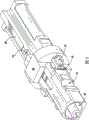
参照图2,这里也称为“插头”的本发明的连接器组件40包括容纳有连接器子组件44(即预先组装好的套管支持器模块)的插头外壳42,连接器子组件44支持套管46。连接器子组件44和套管46是通过插头外壳42的一个开口端可达到的,以便该套管能够被光学连接到另一连接器组件或插头或者插座的套管。其中,相比于传统的连接器10(图1),连接器组件40的覆盖指(shrouding finger)48在长度上减小了,以便使两个连接器组件能格外地彼此更好地配合。其导致的任何减小的保护在需要更凸出的套管46的情况下通过增加的柔性来得到补偿。更凸出的套管46还便于更有效的预先组装和端接,包括抛光等。连接器组件40的内部组件和插头外壳42的有键的构造要求沿一个特定的取向组装连接器组件40,如在下面更详细地描述的那样。这关注于对一种不允许多个方向(即两个180度的相反方向)来组装连接器部件的可替换保持方法的未解决的需求,从而消除了对由操作者固定和确认以便确保连接器子组件44被适当取向的要求。相比于传统的连接器10,插头外壳42的另一端是更开放的。这一事实和将在下面更详细描述的所使用的端盖50的构造,便于插头外壳42相对于基本扁平的引入缆线52相对自由的挠性运动(flexuralmovement),该引入缆线52例如包括一个或多个GRP强力构件54(图3,4和7)。传统的Optitap连接器10的一个或多个硅树脂O形环28(图1)可以被单个整体形成的和包覆成型(overmolded)的O形环56所代替,O形环56设置在凹进沟道58内,凹进沟道58被制造到插头外壳42的外表面中。可选地,插头外壳42的外表面包括多个方便的抓握表面。2, the
参照图3,在内部,连接器组件40包括具有一对安全钩62的保持主体60或者胶主体,这对安全钩62配置成用以与制造在连接器子组件44的相对侧内的一对安全钩凹槽64啮合,一旦其被“卡搭(snapped)”到位,安全钩62就保持连接器子组件44靠着胶主体60。这些安全钩62每一个都包括一突出的“指”部件,该“指”部件具有一“钩状”端。由于这些指部件具有一柔性度,所以在连接器子组件44被压在它们之间时它们被偏离原位或弯曲,并且当这些指部件的钩状端与安全钩凹槽64啮合时,它们“卡搭”回位。一旦插头外壳42被固定在保持主体和安全钩之上,插头外壳42的内表面就可以接触安全钩62的外表面,将安全钩62保持在安全钩凹槽64内。有利地,当使得安全钩凹槽64相对于安全钩62在尺寸上稍微大些时,安全钩62或另一子组件保持特征部分使连接器子组件44能绕连接器组件40和胶主体60的轴稍微旋转(最大大约+/-5度)。如果存在适当的倒角和导入细部,连接器部件将在大约45度之下自对准,由此该子组件保持特征部分使连接器子组件44能旋转小于大约45度。该固有的径向浮动降低了有关的制造公差的严格性。这在直插式(in-line)应用中特别重要,在这种应用中,两个连接器组件彼此之间相对刚性地对准以满足机械性能要求。在这些应用中,设置在连接器组件之间的对准套筒经常不能充分地都适应于两个连接器组件,其可具有相反取向。连接器子组件44的轴25(图1)优选地被设置并支持在孔(bore)66(图6)中,孔66被制造在具有安全钩62的胶主体60的端部中。该端部又包括一对对准块68,它们被设计成能确保连接器子组件44在胶主体60面上的适当定位。Referring to FIG. 3 , internally, the
参照图4和5,借助制造到胶主体60的外表面中的一个或多个凹槽70和制造到插头外壳42的内表面中的一个或多个相应突起72(图4),胶主体60与插头外壳42(图4)啮合。因此,胶主体60被“卡搭”到插头外壳42内部内的适当位置。再则,所选择的材料也使这样做更容易,并且凹槽70或突起72二者或者任一可以具有成互补角(complimentary angled)的表面。有利地,插头外壳42内部内的胶主体60的这种机械保持减小了由于热缩活塞作用导致的端面位置变化的问题。重要地,胶主体60的外表面和插头外壳42的内表面又包括相应的平坦和凸起表面。因此,连接器组件40(图4)的插头外壳42和胶主体60的有键的构造要求连接器组件40沿一个特定的取向组装。再则,这关注于对一种不允许多个方向(即,两个180度的相反方向)来组装连接器部件的可替换保持方法的未解决的需求,从而消除了对由操作者固定和确认以便确保连接器子组件44被正确取向的要求。这些有关的几何结构依赖于材料柔性并且利用有关的半刚性主体之间较小的局部过盈量(localizedinterferences)来确定模制公差,同时保持机械完整性。4 and 5, by means of one or
参考图6,胶主体60包括相对较大直径部分74和相对较小直径部分76,较大直径部分74位于接近具有安全钩62的胶主体60的端部的地方,而较小直径部分76位于远离具有安全钩62的胶主体60的端部的地方。当胶主体60被插入插头外壳42时,由于该较大直径部分74接触制造到插头外壳42的内表面中的隔板78,所以该大直径部分74起到天然止挡的作用(参见图4)。如上所述,连接器子组件44(图2-5)的轴25(图1)优选地设置和支持在制造到具有安全钩62的胶主体60的端部中的孔66内。该端部又包括一对对准块68,它们被设计成用以与安全钩62一起确保连接器子组件44在胶主体60面上的适当定位。Referring to FIG. 6, the
在一可替换的实施例中,连接器子组件44的轴25被设置和支持在以前的压接主体14(图1)的两个一半部分14a、14b(图1)之间,其现已去除。这些又被设置在制造到具有安全钩62的胶主体60的端部内的孔66中。如上所述,这使连接器子组件44相对于胶主体60和插头外壳42保持置于中心。在另一可替换的实施例中,以前的压接主体14的两个一半部分14a、14b被组合成单个压接保持器(未示出),该保持器被设置在制造到具有安全钩62的胶主体60的端部中的孔66内。这又使连接器子组件44相对于胶主体60和插头外壳42保持置于中心。In an alternative embodiment, the
参照图7,胶主体60又包括中心沟道80和一对边缘沟道84,中心沟道80被定位成用以接收引入缆线52的至少一根光纤82,而这一对边缘沟道84被定位成用以接收引入缆线52的GRP强力构件54或其它强力构件。如本领域普通技术人员熟知的那样,光纤82(其通常具有大约250μm的直径)和这一对GRP强力构件54被包在引入缆线护套86内。虽然这里示出和描述了GRP强力构件54,但是引入缆线52也可包括其它类型的强力构件,或作为替换。任何这样的强力构件都可以被制造在胶主体60中的一个或多个沟道所容纳。优选地,这一对GRP强力构件54伸入这一对边缘沟道84中大约10mm与大约20mm之间(更优选的,大约17mm),并且边缘沟道84填充有粘合剂,粘合剂用来将引入缆线52粘结到胶主体60。该粘合剂可以是可见光可固化环氧树脂,或者紫外(UV)光或热可固化胶。所有材料的选择取决于期望的拉拔强度、温度暴露范围和耐化学性。在使用可见光可固化环氧树脂的情况下,胶主体60优选是基本透明的,以便可见光能够到达并固化环氧树脂。例如,可以使用天然的聚醚酰亚胺,其同样也提供相对高的耐温性。这种基本透明的材料考虑到了粘合剂填充和光纤路由(routing)处理期间的视觉反馈。有利地,这一对边缘沟道84将粘合剂与中心沟道80和光纤82分开。由于边缘沟道84被密封,所以防止了材料在组装期间流入连接器组件40(图2-4)内部。本发明的连接器组件40易于满足所期望的大约100lbf拉拔强度要求,这是因为使用了胶主体60和粘合剂的缘故。在组装期间,优选地,首先将引入缆线52固定到胶主体60,然后将连接器子组件44(图2-5)加到胶主体60。Referring to FIG. 7, the
在一可替换的实施例中,这一对边缘沟道84被配置成用以接纳一对楔形夹具,它们由一对未压接(uncrimped)带支持在适当位置。这些楔形夹具和未压接带通过压接被随后固定到GRP强力构件54上,从而将引入缆线52固定到胶主体60。这代表一种非粘合剂方案。In an alternative embodiment, the pair of edge channels 84 are configured to receive a pair of wedge clamps held in place by a pair of uncrimped straps. These wedge clamps and uncrimped straps are then secured to the
参照图8,上述的端盖50包括插入端88,其被配置成用以妥贴地插入插头外壳42(图2和3)的“后”端。端盖50又包括锥状端90,其被制造有槽口92,该槽口92被配置成用以接收基本扁平的引入缆线52(图7),引入缆线52穿过端盖50并进入插头外壳42。Referring to Figure 8, the
如上所述,本发明的保持主体60被诸如保持安全钩62之类的一个或多个耦连部件耦连到连接器子组件44。在传统的连接器组件中,光纤和/或强力构件随着时间过去而有的移动可能导致包括套管的连接器组件相对于连接器外部外壳或插头护罩向前推进或突出,因此导致产生没有能力适当互连的有缺陷的引入缆线。一旦卡搭到位,位于突起72周围的止挡可以阻止保持主体60经由插头组件的前端或连接端而被移走。因此,当光纤或强力构件被推进进入保持主体60时,保持主体可被阻止在插头外壳42内内部地移动到预定点之外。通过将连接器子组件44耦连到保持主体60,于是该连接器子组件也被阻止突出到预定点之外,提供了随着时间过去也有能力适当互连的引入缆线。在一个实施例中,插头外壳42、保持主体60以及它们的接触点能够经受达大约50lbs的力。As noted above, the
虽然这里已经参考优选的实施例以及它们的具体例子说明和描述了本发明,不过对于本领域的普通技术人员来说很显而易见的是,其它实施例和例子也能够执行类似的功能和/或实现同样的结果。例如,两个连接器组件的配合能够通过提供“阴(female)”形式的连接器组件(即,插座)来实现。这种配合顺序可能是插头-插座-插头。所有这些等同的实施例和例子都在本发明的精神和范围内,并且打算被随后的权利要求书所覆盖。While the invention has been illustrated and described herein with reference to preferred embodiments and specific examples thereof, it will be apparent to those of ordinary skill in the art that other embodiments and examples can perform similar functions and/or achieve same result. For example, mating of two connector assemblies can be achieved by providing a "female" version of the connector assembly (ie, a receptacle). This mating sequence may be plug-socket-plug. All such equivalent embodiments and examples are within the spirit and scope of the invention and are intended to be covered by the following claims.
Claims (20)
Translated fromChineseApplications Claiming Priority (3)
| Application Number | Priority Date | Filing Date | Title |
|---|---|---|---|
| US11/504,349 | 2006-08-15 | ||
| US11/504,349US7568844B2 (en) | 2006-08-15 | 2006-08-15 | Ruggedized fiber optic connector assembly |
| PCT/US2007/017968WO2008021351A2 (en) | 2006-08-15 | 2007-08-14 | Ruggedized fiber optic connector assembly |
Publications (2)
| Publication Number | Publication Date |
|---|---|
| CN101501544A CN101501544A (en) | 2009-08-05 |
| CN101501544Btrue CN101501544B (en) | 2012-10-10 |
Family
ID=39082691
Family Applications (1)
| Application Number | Title | Priority Date | Filing Date |
|---|---|---|---|
| CN200780030232XAExpired - Fee RelatedCN101501544B (en) | 2006-08-15 | 2007-08-14 | Reinforced Fiber Optic Connector Assemblies |
Country Status (9)
| Country | Link |
|---|---|
| US (2) | US7568844B2 (en) |
| EP (1) | EP2052286B1 (en) |
| JP (1) | JP4524277B2 (en) |
| CN (1) | CN101501544B (en) |
| AT (1) | ATE534926T1 (en) |
| AU (1) | AU2007284524B2 (en) |
| ES (1) | ES2376598T3 (en) |
| PT (1) | PT2052286E (en) |
| WO (1) | WO2008021351A2 (en) |
Families Citing this family (140)
| Publication number | Priority date | Publication date | Assignee | Title |
|---|---|---|---|---|
| US6962445B2 (en) | 2003-09-08 | 2005-11-08 | Adc Telecommunications, Inc. | Ruggedized fiber optic connection |
| US7568844B2 (en) | 2006-08-15 | 2009-08-04 | Corning Cable Systems Llc | Ruggedized fiber optic connector assembly |
| US7591595B2 (en)* | 2007-01-24 | 2009-09-22 | Adc Telelcommunications, Inc. | Hardened fiber optic adapter |
| US7572065B2 (en) | 2007-01-24 | 2009-08-11 | Adc Telecommunications, Inc. | Hardened fiber optic connector |
| US7738759B2 (en)* | 2007-03-16 | 2010-06-15 | 3M Innovative Properties Company | Optical fiber cable inlet device |
| US7722258B2 (en)* | 2007-05-06 | 2010-05-25 | Adc Telecommunications, Inc. | Interface converter for SC fiber optic connectors |
| US7677814B2 (en)* | 2007-05-06 | 2010-03-16 | Adc Telecommunications, Inc. | Mechanical interface converter for making non-ruggedized fiber optic connectors compatible with a ruggedized fiber optic adapter |
| US7762726B2 (en)* | 2007-12-11 | 2010-07-27 | Adc Telecommunications, Inc. | Hardened fiber optic connection system |
| US20090220197A1 (en)* | 2008-02-22 | 2009-09-03 | Jeffrey Gniadek | Apparatus and fiber optic cable retention system including same |
| US20090214162A1 (en)* | 2008-02-22 | 2009-08-27 | Senko Advanced Components, Inc. | Apparatus and fiber optic cable retention system including same |
| US7708469B2 (en)* | 2008-04-11 | 2010-05-04 | Corning Cable Systems Llc | Fiber optic connector assembly and method for venting gas inside a fiber optic connector sub-assembly |
| EP2283390B1 (en)* | 2008-04-21 | 2016-11-09 | ADC Telecommunications, INC. | Hardened fiber optic connector with connector body joined to cylindrical cable by unitary housing |
| US8467653B2 (en)* | 2008-05-30 | 2013-06-18 | Afl Telecommunications Llc | Fiber optic cable retainer for a fiber optic cable connector assembly |
| US8376631B2 (en) | 2008-08-19 | 2013-02-19 | Belden Cdt (Canada) Inc. | Slide actuated field installable fiber optic connector |
| US8620130B2 (en)* | 2008-08-29 | 2013-12-31 | Corning Cable Systems Llc | Pulling grips for installing a fiber optic assembly |
| US7811006B2 (en)* | 2008-09-02 | 2010-10-12 | Belden CD (Canada) Inc. | Field installable fiber optic connector and installation tool |
| US8285096B2 (en) | 2008-09-30 | 2012-10-09 | Corning Cable Systems Llc | Fiber optic cable assemblies and securing methods |
| US8303193B2 (en)* | 2008-09-30 | 2012-11-06 | Corning Cable Systems Llc | Retention bodies for fiber optic cable assemblies |
| WO2010039837A1 (en)* | 2008-09-30 | 2010-04-08 | Corning Cable Systems Llc | Retention bodies for fiber optic cable assemblies |
| US8272792B2 (en)* | 2008-09-30 | 2012-09-25 | Corning Cable Systems Llc | Retention bodies for fiber optic cable assemblies |
| US7621675B1 (en)* | 2009-02-13 | 2009-11-24 | Ofs Fitel, Llc | Single-piece cable retention housing for hardened outside plant connector |
| US8408815B2 (en)* | 2009-06-18 | 2013-04-02 | Senko Advanced Components, Inc. | Optical fiber connector and adapter |
| AU2010321868B2 (en)* | 2009-11-20 | 2014-12-11 | Adc Telecommunications, Inc. | Fiber optic cable assembly |
| US8870469B2 (en) | 2010-05-12 | 2014-10-28 | Adc Telecommunications, Inc. | Fiber optic connector and method of applying same to a fiber optic cable |
| US8632363B2 (en) | 2010-08-31 | 2014-01-21 | Apple Inc. | Heat sealed connector assembly |
| BR112013025411A2 (en)* | 2011-04-01 | 2016-12-20 | Tyco Electronics Corp | fiber optic adapters and connector devices with mounting capabilities and mounting systems and methods including the same |
| US9188747B2 (en) | 2011-05-23 | 2015-11-17 | Senko Advanced Components, Inc. | True one piece housing fiber optic adapter |
| CN102854571B (en)* | 2011-06-30 | 2017-02-22 | 成都康宁光缆有限公司 | Optical fiber connector, manufacturing method thereof and cable assembly |
| CN103733102B (en) | 2011-08-16 | 2017-03-08 | 康宁光电通信有限责任公司 | Pre-connection cable assembly for indoor/outdoor application |
| WO2013052070A1 (en) | 2011-10-05 | 2013-04-11 | Senko Advanced Components, Inc. | Latching connector with remote release |
| TWM429881U (en)* | 2011-11-14 | 2012-05-21 | Gloriole Electroptic Technology Corp | Fiber optic connector |
| US8939655B2 (en) | 2012-06-29 | 2015-01-27 | Corning Cable Systems Llc | Dust caps, fiber optic connectors, and fiber optic splitter modules incorporating interlocking key features |
| US9304265B2 (en) | 2012-07-26 | 2016-04-05 | Corning Cable Systems Llc | Fiber optic connectors employing moveable optical interfaces with fiber protection features and related components and methods |
| US8974124B2 (en) | 2012-08-16 | 2015-03-10 | Senko Advanced Components, Inc. | Fiber optic connector |
| US9696500B2 (en) | 2012-08-31 | 2017-07-04 | Corning Optical Communications LLC | Female hardened optical connectors for use with hybrid receptacle |
| US8917968B2 (en)* | 2012-11-06 | 2014-12-23 | Corning Optical Communications LLC | Furcation plugs having segregated channels to guide epoxy into passageways for optical fiber furcation, and related assemblies and methods |
| TW201430415A (en)* | 2013-01-22 | 2014-08-01 | Hon Hai Prec Ind Co Ltd | Optical fiber coupling connector |
| US9256033B2 (en)* | 2013-01-23 | 2016-02-09 | Commscope, Inc. Of North Carolina | Cylindrical optical ferrule alignment apparatus |
| US10191226B2 (en) | 2013-01-23 | 2019-01-29 | Commscope, Inc. Of North Carolina | Cylindrical optical ferrule alignment apparatus |
| US9513444B2 (en)* | 2013-02-26 | 2016-12-06 | Corning Optical Communications LLC | Female hardened optical connectors for use with male plug connectors |
| US9052469B2 (en) | 2013-04-26 | 2015-06-09 | Corning Cable Systems Llc | Preterminated fiber optic connector sub-assemblies, and related fiber optic connectors, cable assemblies, and methods |
| WO2014179376A2 (en) | 2013-05-02 | 2014-11-06 | Corning Optical Communications LLC | Connector assemblies and methods for providing sealing and strain-relief |
| US9268103B2 (en) | 2013-05-10 | 2016-02-23 | Senko Advanced Components, Inc. | Interlockable fiber optic connector adaptors |
| US9360649B2 (en) | 2013-05-22 | 2016-06-07 | Senko Advanced Components, Inc. | Cable guide for fiber optic cables |
| WO2014206976A1 (en) | 2013-06-27 | 2014-12-31 | Tyco Electronics Raychem Bvba | Fiber optic cable anchoring device for use with fiber optic connectors and methods of using the same |
| US9618703B2 (en) | 2013-10-03 | 2017-04-11 | Senko Advanced Components, Inc. | Connector housing for securing an optical cable and methods of use and manufacture thereof |
| US9477049B2 (en) | 2013-12-20 | 2016-10-25 | Senko Advanced Components, Inc. | Lockable connectors and connection assemblies |
| US9535230B2 (en) | 2014-01-31 | 2017-01-03 | Senko Advanced Components, Inc. | Integrated fiber optic cable fan-out connector |
| US9297964B2 (en) | 2014-04-18 | 2016-03-29 | Senko Advanced Components, Inc. | Optical fiber connector assembly |
| US9274287B2 (en) | 2014-05-13 | 2016-03-01 | Senko Advanced Components, Inc. | Optical fiber connector and ferrule |
| US9618702B2 (en) | 2014-06-09 | 2017-04-11 | Senko Advanced Components, Inc. | Reduced-profile data transmission element connectors, adapters, and connection assemblies thereof |
| US9766414B2 (en) | 2014-06-27 | 2017-09-19 | Commscope Technologies Llc | Indexing terminals for supporting a bidirectional indexing architecture |
| ES2841133T3 (en) | 2014-08-06 | 2021-07-07 | Prysmian Spa | Fiber optic connector set |
| US9599778B2 (en) | 2014-10-22 | 2017-03-21 | Senko Advanced Components, Inc. | Latching connector with remote release |
| CN204359965U (en) | 2014-11-20 | 2015-05-27 | 泰科电子(上海)有限公司 | Connector system |
| WO2016095213A1 (en) | 2014-12-19 | 2016-06-23 | Tyco Electronics (Shanghai) Co., Ltd. | Hardened fiber optic connector with pre-compressed spring |
| US9494745B2 (en) | 2015-01-16 | 2016-11-15 | Senko Advanced Components, Inc. | Sealable communication cable connection assemblies |
| US9658409B2 (en) | 2015-03-03 | 2017-05-23 | Senko Advanced Components, Inc. | Optical fiber connector with changeable polarity |
| US9482825B1 (en)* | 2015-04-28 | 2016-11-01 | Senko Advanced Components, Inc | Ingress protected optical fiber connector having small diameter (mini-IP connector) |
| US9448369B1 (en)* | 2015-04-28 | 2016-09-20 | Senko Advanced Components, Inc. | Ingress protected optical fiber connector having small diameter (mini-IP connector) |
| US9684139B2 (en) | 2015-05-29 | 2017-06-20 | Senko Advanced Components, Inc. | Optical fiber connector with changeable gender |
| US10473868B2 (en)* | 2015-11-30 | 2019-11-12 | Corning Optical Communications, Llc | Optical connector plug having a removable and replaceable mating interface |
| US9726830B1 (en) | 2016-06-28 | 2017-08-08 | Senko Advanced Components, Inc. | Connector and adapter system for two-fiber mechanical transfer type ferrule |
| US10078188B1 (en) | 2016-12-05 | 2018-09-18 | Senko Advanced Components, Inc. | Springless push/pull fiber optic connector |
| US10228521B2 (en) | 2016-12-05 | 2019-03-12 | Senko Advanced Components, Inc. | Narrow width adapters and connectors with modular latching arm |
| US11333836B2 (en) | 2017-01-30 | 2022-05-17 | Senko Advanced Components, Inc. | Adapter for optical connectors |
| CN110249248B (en) | 2017-01-30 | 2021-07-27 | 扇港元器件股份有限公司 | Optical connectors with reversible polarity |
| US10444444B2 (en) | 2017-01-30 | 2019-10-15 | Senko Advanced Components, Inc. | Remote release tab connector assembly |
| US10725248B2 (en) | 2017-01-30 | 2020-07-28 | Senko Advanced Components, Inc. | Fiber optic receptacle with integrated device therein incorporating a behind-the-wall fiber optic receptacle |
| US10185100B2 (en) | 2017-01-30 | 2019-01-22 | Senko Advanced Components, Inc | Modular connector and adapter assembly using a removable anchor device |
| US10416394B2 (en) | 2017-01-30 | 2019-09-17 | Senko Advanced Components, Inc. | Fiber optic receptacle with integrated device therein |
| US9989712B1 (en) | 2017-03-20 | 2018-06-05 | Senko Advanced Components, Inc | MPO connector assembly with push-pull tab |
| US10359583B2 (en) | 2017-04-07 | 2019-07-23 | Senko Advanced Components, Inc. | Behind the wall optical connector with reduced components |
| US10209461B2 (en) | 2017-04-07 | 2019-02-19 | Senko Advanced Components | Behind the wall optical connector with reduced components |
| US10754098B2 (en) | 2017-04-07 | 2020-08-25 | Senko Advanced Components, Inc. | Behind the wall optical connector with reduced components |
| US10989884B2 (en) | 2017-04-07 | 2021-04-27 | Senko Advanced Components, Inc. | Behind the wall optical connector with reduced components |
| US10718910B2 (en) | 2017-05-03 | 2020-07-21 | Senko Advanced Components, Inc | Field terminated ruggedized fiber optic connector system |
| US10146016B1 (en) | 2017-05-10 | 2018-12-04 | Senko Advanced Components, Inc | MPO micro-latchlock connector |
| US10401576B2 (en) | 2017-05-10 | 2019-09-03 | Senko Advanced Components, Inc. | MPO micro-latch-lock connector |
| US10295759B2 (en) | 2017-05-18 | 2019-05-21 | Senko Advanced Components, Inc. | Optical connector with forward-biasing projections |
| WO2018222740A1 (en) | 2017-05-30 | 2018-12-06 | Commscope Technologies Llc | Reconfigurable optical networks |
| US10359576B2 (en) | 2017-06-15 | 2019-07-23 | Senko Advanced Components, Inc. | SC low profile connector with optional boot |
| CN111051945B (en) | 2017-06-28 | 2023-12-29 | 康宁研究与开发公司 | Compact fiber optic connector, cable assembly and method of making the same |
| US11822133B2 (en) | 2017-07-14 | 2023-11-21 | Senko Advanced Components, Inc. | Ultra-small form factor optical connector and adapter |
| US10281669B2 (en) | 2017-07-14 | 2019-05-07 | Senko Advance Components, Inc. | Ultra-small form factor optical connectors |
| US12001064B2 (en) | 2017-07-14 | 2024-06-04 | Senko Advanced Components, Inc. | Small form factor fiber optic connector with multi-purpose boot |
| US10718911B2 (en) | 2017-08-24 | 2020-07-21 | Senko Advanced Components, Inc. | Ultra-small form factor optical connectors using a push-pull boot receptacle release |
| US10641972B2 (en) | 2017-08-17 | 2020-05-05 | Senko Advanced Components, Inc | Anti-jam alignment sleeve holder or connector housing for a ferrule assembly |
| EP3460548A1 (en) | 2017-09-25 | 2019-03-27 | Fujikura Ltd. | Clamp member, optical connector, and manufacturing method of optical connector |
| US10444442B2 (en) | 2017-11-03 | 2019-10-15 | Senko Advanced Components, Inc. | MPO optical fiber connector |
| US11002923B2 (en) | 2017-11-21 | 2021-05-11 | Senko Advanced Components, Inc. | Fiber optic connector with cable boot release having a two-piece clip assembly |
| USD1002540S1 (en) | 2017-11-30 | 2023-10-24 | Corning Research & Development Corporation | Connector for making optical connections |
| USD868694S1 (en)* | 2017-11-30 | 2019-12-03 | Corning Research & Development Corporation | Connector for making optical connections |
| US11016250B2 (en)* | 2017-12-19 | 2021-05-25 | Us Conec, Ltd. | Mini duplex connector with push-pull polarity mechanism, carrier, and rail-receiving crimp body |
| US10678000B2 (en) | 2018-01-05 | 2020-06-09 | Senko Advanced Components, Inc. | Pull rod and alignment key for a fiber optic connector and adapter |
| WO2019173350A1 (en)* | 2018-03-06 | 2019-09-12 | Commscope Technologies Llc | Modular hardened optical fiber connector and assembly method thereof |
| CN108241191B (en)* | 2018-03-12 | 2020-01-14 | 四川天邑康和通信股份有限公司 | Process flow for automatically producing optical fiber connector |
| WO2019183070A2 (en) | 2018-03-19 | 2019-09-26 | Senko Advanced Components, Inc. | Removal tool for removing a plural of micro optical connectors from an adapter interface |
| EP3776038B1 (en) | 2018-03-28 | 2024-07-03 | Senko Advanced Components Inc. | Small form factor fiber optic connector with multi-purpose boot |
| US11041993B2 (en) | 2018-04-19 | 2021-06-22 | Senko Advanced Components, Inc. | Fiber optic adapter with removable insert for polarity change and removal tool for the same |
| JP6397599B1 (en) | 2018-05-21 | 2018-09-26 | 株式会社フジクラ | Fusion splicer and optical fiber reinforcing method |
| US10921528B2 (en) | 2018-06-07 | 2021-02-16 | Senko Advanced Components, Inc. | Dual spring multi-fiber optic connector |
| CN112088327A (en) | 2018-07-15 | 2020-12-15 | 扇港元器件股份有限公司 | Subminiature Optical Connectors and Adapters |
| MX2021001415A (en)* | 2018-08-03 | 2021-06-08 | Ppc Broadband Inc | Fiber optical connector with retention feature. |
| US10444441B1 (en) | 2018-08-10 | 2019-10-15 | Senko Advanced Components, Inc. | Pivotable housing for a fiber optic connector |
| US11073664B2 (en) | 2018-08-13 | 2021-07-27 | Senko Advanced Components, Inc. | Cable boot assembly for releasing fiber optic connector from a receptacle |
| US10921530B2 (en) | 2018-09-12 | 2021-02-16 | Senko Advanced Components, Inc. | LC type connector with push/pull assembly for releasing connector from a receptacle using a cable boot |
| WO2020055440A1 (en) | 2018-09-12 | 2020-03-19 | Senko Advanced Componetns, Inc. | Lc type connector with clip-on push/pull tab for releasing connector from a receptacle using a cable boot |
| US10921531B2 (en) | 2018-09-12 | 2021-02-16 | Senko Advanced Components, Inc. | LC type connector with push/pull assembly for releasing connector from a receptacle using a cable boot |
| US11806831B2 (en) | 2018-11-21 | 2023-11-07 | Senko Advanced Components, Inc. | Fixture and method for polishing fiber optic connector ferrules |
| US11175464B2 (en) | 2018-11-25 | 2021-11-16 | Senko Advanced Components, Inc. | Open ended spring body for use in an optical fiber connector |
| US10761288B2 (en) | 2018-12-06 | 2020-09-01 | Ofs Fitel, Llc | Armored fiber optic cable connector assembly |
| TWM577119U (en)* | 2019-01-09 | 2019-04-21 | 建毅科技股份有限公司 | Optical fibre connector |
| US11689247B2 (en) | 2019-01-16 | 2023-06-27 | Mertek Industries, Llc | Patch cord including wireless components |
| US11579379B2 (en) | 2019-03-28 | 2023-02-14 | Senko Advanced Components, Inc. | Fiber optic adapter assembly |
| US12038613B2 (en) | 2019-03-28 | 2024-07-16 | Senko Advanced Components, Inc. | Behind-the-wall optical connector and assembly of the same |
| US11340406B2 (en) | 2019-04-19 | 2022-05-24 | Senko Advanced Components, Inc. | Small form factor fiber optic connector with resilient latching mechanism for securing within a hook-less receptacle |
| WO2020252355A1 (en) | 2019-06-13 | 2020-12-17 | Senko Advanced Components, Inc | Lever actuated latch arm for releasing a fiber optic connector from a receptacle port and method of use |
| CN114600018B (en) | 2019-07-23 | 2024-04-09 | 扇港元器件有限公司 | Ultra-small receptacle for receiving a fiber optic connector opposite a ferrule assembly |
| CN110542952B (en) | 2019-07-26 | 2021-05-18 | 华为技术有限公司 | Optical fiber connector and optical fiber connector |
| US11353664B1 (en) | 2019-08-21 | 2022-06-07 | Senko Advanced Components, Inc. | Fiber optic connector |
| WO2021067241A1 (en) | 2019-09-30 | 2021-04-08 | Mertek Industries, Llc | Patch panel traceable networking system |
| CN112711107B (en)* | 2019-10-25 | 2024-06-25 | 扇港元器件股份有限公司 | Optical fiber microconnector |
| WO2021097304A1 (en) | 2019-11-13 | 2021-05-20 | Senko Advanced Components, Inc. | Fiber optic connector |
| WO2021113717A1 (en) | 2019-12-05 | 2021-06-10 | Commscope Technologies Llc | Terminal formed by sequentially assembled modules |
| JP7295000B2 (en)* | 2019-12-05 | 2023-06-20 | 住友電工オプティフロンティア株式会社 | Optical connector adapter caps and optical connector assemblies |
| USD949107S1 (en) | 2019-12-20 | 2022-04-19 | Corning Research & Development Corporation | Dustplug for a multiport optical connection device |
| EP4139729A4 (en) | 2020-04-20 | 2024-06-05 | CommScope Technologies LLC | Fiber optic enclosure with ability to customize and/or upgrade |
| US11611180B2 (en) | 2020-06-19 | 2023-03-21 | Corning Optical Communications Rf Llc | Coaxial cable connector assemblies with contained adhesives and methods for using the same |
| US11604320B2 (en) | 2020-09-30 | 2023-03-14 | Corning Research & Development Corporation | Connector assemblies for telecommunication enclosures |
| RU2748013C1 (en)* | 2020-10-23 | 2021-05-18 | Общество с ограниченной ответственностью «Конструкторское бюро «Модуль» | Universal fiber-optic connector |
| AU2021368055A1 (en) | 2020-10-30 | 2023-06-08 | Corning Research & Development Corporation | Female fiber optic connectors having a rocker latch arm and methods of making the same |
| US11994722B2 (en) | 2020-11-30 | 2024-05-28 | Corning Research & Development Corporation | Fiber optic adapter assemblies including an adapter housing and a locking housing |
| US11927810B2 (en) | 2020-11-30 | 2024-03-12 | Corning Research & Development Corporation | Fiber optic adapter assemblies including a conversion housing and a release member |
| US11880076B2 (en) | 2020-11-30 | 2024-01-23 | Corning Research & Development Corporation | Fiber optic adapter assemblies including a conversion housing and a release housing |
| TWI767621B (en)* | 2021-03-21 | 2022-06-11 | 立佳興業股份有限公司 | Dust-prevented adapter |
| USD1013638S1 (en)* | 2021-08-27 | 2024-02-06 | A.J.World Co., Ltd. | Optical fiber connector |
| USD1060249S1 (en) | 2021-08-30 | 2025-02-04 | Corning Research & Development Corporation | Multifiber connector for making optical connections |
| US20230146684A1 (en)* | 2021-11-10 | 2023-05-11 | Corning Research & Development Corporation | Fiber optic connector having improved cable termination along with cable assemblies and methods of making the same |
| CN119376048B (en)* | 2024-12-30 | 2025-07-04 | 江苏南方通信科技有限公司 | Prefabricated end butterfly-shaped lead-in optical cable |
Citations (4)
| Publication number | Priority date | Publication date | Assignee | Title |
|---|---|---|---|---|
| US5129023A (en)* | 1991-05-14 | 1992-07-07 | At&T Bell Laboratories | Optical fiber connector having enhanced provisions for interconnection and for prevention of optical and mechanical disconnection |
| US5764833A (en)* | 1993-03-31 | 1998-06-09 | Sumitomo Electric Industries, Ltd. | Optical fiber array |
| US5887095A (en)* | 1995-03-08 | 1999-03-23 | Nippon Telegraph & Telephone Corporation | Optical receptacle and housing therefor |
| US6224270B1 (en)* | 1996-07-15 | 2001-05-01 | Seiko Instruments Inc. | Universal optical fiber connectors and basic plugs thereof |
Family Cites Families (51)
| Publication number | Priority date | Publication date | Assignee | Title |
|---|---|---|---|---|
| US4354731A (en) | 1979-10-02 | 1982-10-19 | E. I. Du Pont De Nemours And Company | Self-aligning optical fiber connector |
| US4773725A (en)* | 1982-05-24 | 1988-09-27 | Amp Incorporated | Termination of a fiber optic transmission member and method therefore |
| US4934785A (en)* | 1983-08-29 | 1990-06-19 | American Telephone And Telegraph Company | Optical fiber connector |
| WO1988009982A1 (en)* | 1987-06-09 | 1988-12-15 | Hiroshi Kawashima | Apparatus for guiding an aircraft on the ground |
| US5028114A (en) | 1988-09-29 | 1991-07-02 | Siemens Aktiengesellschaft | Plug connector for fiber optic cables |
| US4991929A (en)* | 1989-05-12 | 1991-02-12 | Amp Incorporated | Index matching film |
| US5042891A (en)* | 1990-06-21 | 1991-08-27 | Amp Incorporated | Active device mount assembly with interface mount for push-pull coupling type optical fiber connectors |
| EP0468671B1 (en) | 1990-07-27 | 1996-01-03 | The Whitaker Corporation | Fiber optic interconnect for wall outlet |
| US5210810A (en) | 1991-12-19 | 1993-05-11 | At&T Bell Laboratories | Hermaphroditic connector for single fiber optical cable |
| US6355976B1 (en)* | 1992-05-14 | 2002-03-12 | Reveo, Inc | Three-dimensional packaging technology for multi-layered integrated circuits |
| EP0579889B1 (en)* | 1992-07-22 | 1997-06-04 | Wilhelm A. Keller | Mixer and attachment |
| US5343548A (en)* | 1992-12-15 | 1994-08-30 | International Business Machines Corporation | Method and apparatus for batch, active alignment of laser arrays to fiber arrays |
| US5436994A (en) | 1993-02-26 | 1995-07-25 | Ott; Conrad L. | Ferrule holder for fiber optic connector |
| US5481634A (en)* | 1994-06-24 | 1996-01-02 | At&T Corp. | Connector for optical fiber |
| US5465313A (en)* | 1994-06-29 | 1995-11-07 | Molex Incorporated | Optical fiber connector and method of fabricating same |
| US5461690A (en)* | 1994-07-29 | 1995-10-24 | At&T Ipm Corp. | Bend-limiting apparatus for a cable |
| US5720907A (en)* | 1995-04-24 | 1998-02-24 | Lucent Technologies Inc. | Method for manufacturing an optical connector assembly |
| US5606635A (en)* | 1995-06-07 | 1997-02-25 | Mcdonnell Douglas Corporation | Fiber optic connector having at least one microactuator for precisely aligning an optical fiber and an associated fabrication method |
| US5638474A (en)* | 1995-08-30 | 1997-06-10 | Lucent Technologies Inc. | Anti-snag latch assembly for a connector |
| US5719977A (en)* | 1996-04-23 | 1998-02-17 | Lucent Technologies Inc. | Optical connector with immovable ferrule |
| US5751874A (en) | 1996-09-13 | 1998-05-12 | Nuvisions International, Inc. | Coupling device for linking optical fiber connectors |
| US5993071A (en) | 1996-09-30 | 1999-11-30 | The Whitaker Corporation | Apparatus for connecting optical fibre connectors |
| US5778122A (en) | 1996-12-24 | 1998-07-07 | Siecor Corporation | Fiber optic cable assembly for interconnecting optical fibers within a receptacle mounted within the wall of an enclosure |
| US5923804A (en) | 1997-03-31 | 1999-07-13 | Siecor Corporation | Fiber optic connector and an associated method of fabrication |
| US6497516B1 (en)* | 1997-12-17 | 2002-12-24 | Sumitomo Electric Industries, Ltd. | Guide pin for optical fiber connectors and optical fiber connector plug |
| US6097873A (en)* | 1998-01-14 | 2000-08-01 | Lucent Technologies Inc. | Optical fiber attenuator device using an elastomeric attenuator member |
| US6079881A (en) | 1998-04-08 | 2000-06-27 | Molex Incorporated | Fiber optic connector receptacle assembly |
| US6149313A (en) | 1998-12-31 | 2000-11-21 | Siecor Operations, Llc | Gender selectable fiber optic connector and associated fabrication method |
| US6234685B1 (en) | 1999-05-13 | 2001-05-22 | Lucent Technologies Inc. | Quick connect fiber optic connector having a deformable barrel |
| US6634796B2 (en) | 1999-06-30 | 2003-10-21 | Corning Cable Systems Llc | Polarity reversal for fiber optic connections |
| US6234683B1 (en) | 1999-09-13 | 2001-05-22 | Stratos Lightwave, Inc. | Field repairable hermaphroditic connector |
| US6648520B2 (en) | 2001-09-28 | 2003-11-18 | Corning Cable Systems Llc | Fiber optic plug |
| US7111990B2 (en) | 2000-05-26 | 2006-09-26 | Corning Cable Systems, Llc | Figure-eight preconnectorized fiber optic drop cables and assemblies |
| US7113679B2 (en) | 2000-05-26 | 2006-09-26 | Corning Cable Systems, Llc | Fiber optic drop cables and preconnectorized assemblies having toning portions |
| US7090407B2 (en) | 2000-05-26 | 2006-08-15 | Corning Cable Systems Llc | Preconnectorized fiber optic drop cables and assemblies for efficient deployment |
| US7090406B2 (en) | 2000-05-26 | 2006-08-15 | Corning Cable Systems Llc | Preconnectorized fiber optic drop cables and assemblies |
| US6439780B1 (en)* | 2000-08-31 | 2002-08-27 | Corning Cable Systems Llc | Field-installable fiber optic ribbon connector and installation tool |
| US6910812B2 (en)* | 2001-05-15 | 2005-06-28 | Peregrine Semiconductor Corporation | Small-scale optoelectronic package |
| US6579014B2 (en) | 2001-09-28 | 2003-06-17 | Corning Cable Systems Llc | Fiber optic receptacle |
| JP2004086137A (en)* | 2002-07-01 | 2004-03-18 | Seiko Epson Corp | Optical transceiver and method of manufacturing the same |
| US7144163B2 (en)* | 2003-01-27 | 2006-12-05 | Fujikura Ltd. | Optical connector with shutter, shutter unit, and inner piece |
| DE10332015A1 (en)* | 2003-07-14 | 2005-03-03 | Infineon Technologies Ag | Optoelectronic module with transmitter chip and connector for the module to an optical fiber and to a circuit board, and method of making the same |
| US7077576B2 (en) | 2003-09-30 | 2006-07-18 | Corning Cable Systems Llc | Fiber optic connection for applying axial biasing force to multifiber ferrule |
| US7184634B2 (en)* | 2004-03-25 | 2007-02-27 | Corning Cable Systems, Llc. | Fiber optic drop cables suitable for outdoor fiber to the subscriber applications |
| US7206482B2 (en)* | 2004-03-25 | 2007-04-17 | Corning Cable Systems, Llc. | Protective casings for optical fibers |
| US7146090B2 (en)* | 2004-06-17 | 2006-12-05 | Corning Cable Systems Llc | Fiber optic cable and plug assembly |
| US7244066B2 (en)* | 2005-02-25 | 2007-07-17 | Corning Cable Systems Llc | Fiber optic receptacle and plug assembly including alignment sleeve insert |
| US7264402B2 (en)* | 2005-03-10 | 2007-09-04 | Corning Cable Systems Llc | Multi-fiber optic receptacle and plug assembly |
| US7150567B1 (en)* | 2005-05-27 | 2006-12-19 | Corning Cable Systems Llc | Fiber optic connector having keyed ferrule holder |
| US20070025665A1 (en)* | 2005-07-29 | 2007-02-01 | Dean David L Jr | Multi-fiber fiber optic assembly |
| US7568844B2 (en) | 2006-08-15 | 2009-08-04 | Corning Cable Systems Llc | Ruggedized fiber optic connector assembly |
- 2006
- 2006-08-15USUS11/504,349patent/US7568844B2/enactiveActive
- 2006-11-27JPJP2006318107Apatent/JP4524277B2/ennot_activeExpired - Fee Related
- 2007
- 2007-08-14CNCN200780030232XApatent/CN101501544B/ennot_activeExpired - Fee Related
- 2007-08-14EPEP07836795Apatent/EP2052286B1/ennot_activeNot-in-force
- 2007-08-14WOPCT/US2007/017968patent/WO2008021351A2/enactiveApplication Filing
- 2007-08-14AUAU2007284524Apatent/AU2007284524B2/ennot_activeCeased
- 2007-08-14ESES07836795Tpatent/ES2376598T3/enactiveActive
- 2007-08-14PTPT07836795Tpatent/PT2052286E/enunknown
- 2007-08-14ATAT07836795Tpatent/ATE534926T1/enactive
- 2009
- 2009-08-03USUS12/534,796patent/US8523455B2/ennot_activeExpired - Fee Related
Patent Citations (4)
| Publication number | Priority date | Publication date | Assignee | Title |
|---|---|---|---|---|
| US5129023A (en)* | 1991-05-14 | 1992-07-07 | At&T Bell Laboratories | Optical fiber connector having enhanced provisions for interconnection and for prevention of optical and mechanical disconnection |
| US5764833A (en)* | 1993-03-31 | 1998-06-09 | Sumitomo Electric Industries, Ltd. | Optical fiber array |
| US5887095A (en)* | 1995-03-08 | 1999-03-23 | Nippon Telegraph & Telephone Corporation | Optical receptacle and housing therefor |
| US6224270B1 (en)* | 1996-07-15 | 2001-05-01 | Seiko Instruments Inc. | Universal optical fiber connectors and basic plugs thereof |
Also Published As
| Publication number | Publication date |
|---|---|
| AU2007284524B2 (en) | 2012-06-14 |
| US20080044137A1 (en) | 2008-02-21 |
| US7568844B2 (en) | 2009-08-04 |
| JP2008052236A (en) | 2008-03-06 |
| JP4524277B2 (en) | 2010-08-11 |
| ES2376598T3 (en) | 2012-03-15 |
| ATE534926T1 (en) | 2011-12-15 |
| EP2052286B1 (en) | 2011-11-23 |
| US20090310916A1 (en) | 2009-12-17 |
| PT2052286E (en) | 2012-02-06 |
| EP2052286A2 (en) | 2009-04-29 |
| US8523455B2 (en) | 2013-09-03 |
| AU2007284524A1 (en) | 2008-02-21 |
| WO2008021351A3 (en) | 2008-05-22 |
| WO2008021351A2 (en) | 2008-02-21 |
| CN101501544A (en) | 2009-08-05 |
Similar Documents
| Publication | Publication Date | Title |
|---|---|---|
| CN101501544B (en) | Reinforced Fiber Optic Connector Assemblies | |
| CN102778731B (en) | Multi-fiber fiber optic receptacle and plug assembly | |
| US7244066B2 (en) | Fiber optic receptacle and plug assembly including alignment sleeve insert | |
| US8506173B2 (en) | Multi-fiber fiber optic receptacle and plug assembly | |
| US7137742B2 (en) | Fiber optic receptacle and plug assemblies with alignment and keying features | |
| HK1140026B (en) | Multi-fiber fiber optic receptacle and plug assembly |
Legal Events
| Date | Code | Title | Description |
|---|---|---|---|
| C06 | Publication | ||
| PB01 | Publication | ||
| C10 | Entry into substantive examination | ||
| SE01 | Entry into force of request for substantive examination | ||
| C14 | Grant of patent or utility model | ||
| GR01 | Patent grant | ||
| CF01 | Termination of patent right due to non-payment of annual fee | ||
| CF01 | Termination of patent right due to non-payment of annual fee | Granted publication date:20121010 Termination date:20200814 |