CN101500650A - Ultrasound system for craniocerebral blood flow imaging and microbubble-enhanced clot lysis - Google Patents
Ultrasound system for craniocerebral blood flow imaging and microbubble-enhanced clot lysisDownload PDFInfo
- Publication number
- CN101500650A CN101500650ACNA200780029775XACN200780029775ACN101500650ACN 101500650 ACN101500650 ACN 101500650ACN A200780029775X ACNA200780029775X ACN A200780029775XACN 200780029775 ACN200780029775 ACN 200780029775ACN 101500650 ACN101500650 ACN 101500650A
- Authority
- CN
- China
- Prior art keywords
- image
- transducer array
- wave beam
- headgear
- therapy system
- Prior art date
- Legal status (The legal status is an assumption and is not a legal conclusion. Google has not performed a legal analysis and makes no representation as to the accuracy of the status listed.)
- Granted
Links
Images


Classifications
- A—HUMAN NECESSITIES
- A61—MEDICAL OR VETERINARY SCIENCE; HYGIENE
- A61B—DIAGNOSIS; SURGERY; IDENTIFICATION
- A61B8/00—Diagnosis using ultrasonic, sonic or infrasonic waves
- A61B8/08—Clinical applications
- A61B8/0808—Clinical applications for diagnosis of the brain
- A61B8/0816—Clinical applications for diagnosis of the brain using echo-encephalography
- A—HUMAN NECESSITIES
- A61—MEDICAL OR VETERINARY SCIENCE; HYGIENE
- A61B—DIAGNOSIS; SURGERY; IDENTIFICATION
- A61B17/00—Surgical instruments, devices or methods
- A61B17/22—Implements for squeezing-off ulcers or the like on inner organs of the body; Implements for scraping-out cavities of body organs, e.g. bones; for invasive removal or destruction of calculus using mechanical vibrations; for removing obstructions in blood vessels, not otherwise provided for
- A61B17/22004—Implements for squeezing-off ulcers or the like on inner organs of the body; Implements for scraping-out cavities of body organs, e.g. bones; for invasive removal or destruction of calculus using mechanical vibrations; for removing obstructions in blood vessels, not otherwise provided for using mechanical vibrations, e.g. ultrasonic shock waves
- A—HUMAN NECESSITIES
- A61—MEDICAL OR VETERINARY SCIENCE; HYGIENE
- A61B—DIAGNOSIS; SURGERY; IDENTIFICATION
- A61B5/00—Measuring for diagnostic purposes; Identification of persons
- A61B5/02—Detecting, measuring or recording for evaluating the cardiovascular system, e.g. pulse, heart rate, blood pressure or blood flow
- A61B5/02007—Evaluating blood vessel condition, e.g. elasticity, compliance
- A—HUMAN NECESSITIES
- A61—MEDICAL OR VETERINARY SCIENCE; HYGIENE
- A61B—DIAGNOSIS; SURGERY; IDENTIFICATION
- A61B5/00—Measuring for diagnostic purposes; Identification of persons
- A61B5/68—Arrangements of detecting, measuring or recording means, e.g. sensors, in relation to patient
- A61B5/6801—Arrangements of detecting, measuring or recording means, e.g. sensors, in relation to patient specially adapted to be attached to or worn on the body surface
- A61B5/6813—Specially adapted to be attached to a specific body part
- A61B5/6814—Head
- A—HUMAN NECESSITIES
- A61—MEDICAL OR VETERINARY SCIENCE; HYGIENE
- A61B—DIAGNOSIS; SURGERY; IDENTIFICATION
- A61B8/00—Diagnosis using ultrasonic, sonic or infrasonic waves
- A61B8/06—Measuring blood flow
- A—HUMAN NECESSITIES
- A61—MEDICAL OR VETERINARY SCIENCE; HYGIENE
- A61B—DIAGNOSIS; SURGERY; IDENTIFICATION
- A61B8/00—Diagnosis using ultrasonic, sonic or infrasonic waves
- A61B8/08—Clinical applications
- A—HUMAN NECESSITIES
- A61—MEDICAL OR VETERINARY SCIENCE; HYGIENE
- A61B—DIAGNOSIS; SURGERY; IDENTIFICATION
- A61B8/00—Diagnosis using ultrasonic, sonic or infrasonic waves
- A61B8/08—Clinical applications
- A61B8/0808—Clinical applications for diagnosis of the brain
- A—HUMAN NECESSITIES
- A61—MEDICAL OR VETERINARY SCIENCE; HYGIENE
- A61B—DIAGNOSIS; SURGERY; IDENTIFICATION
- A61B8/00—Diagnosis using ultrasonic, sonic or infrasonic waves
- A61B8/08—Clinical applications
- A61B8/0833—Clinical applications involving detecting or locating foreign bodies or organic structures
- A61B8/085—Clinical applications involving detecting or locating foreign bodies or organic structures for locating body or organic structures, e.g. tumours, calculi, blood vessels, nodules
- A—HUMAN NECESSITIES
- A61—MEDICAL OR VETERINARY SCIENCE; HYGIENE
- A61B—DIAGNOSIS; SURGERY; IDENTIFICATION
- A61B8/00—Diagnosis using ultrasonic, sonic or infrasonic waves
- A61B8/13—Tomography
- A—HUMAN NECESSITIES
- A61—MEDICAL OR VETERINARY SCIENCE; HYGIENE
- A61B—DIAGNOSIS; SURGERY; IDENTIFICATION
- A61B8/00—Diagnosis using ultrasonic, sonic or infrasonic waves
- A61B8/42—Details of probe positioning or probe attachment to the patient
- A61B8/4209—Details of probe positioning or probe attachment to the patient by using holders, e.g. positioning frames
- A61B8/4227—Details of probe positioning or probe attachment to the patient by using holders, e.g. positioning frames characterised by straps, belts, cuffs or braces
- A—HUMAN NECESSITIES
- A61—MEDICAL OR VETERINARY SCIENCE; HYGIENE
- A61B—DIAGNOSIS; SURGERY; IDENTIFICATION
- A61B8/00—Diagnosis using ultrasonic, sonic or infrasonic waves
- A61B8/48—Diagnostic techniques
- A61B8/481—Diagnostic techniques involving the use of contrast agents, e.g. microbubbles introduced into the bloodstream
- A—HUMAN NECESSITIES
- A61—MEDICAL OR VETERINARY SCIENCE; HYGIENE
- A61B—DIAGNOSIS; SURGERY; IDENTIFICATION
- A61B8/00—Diagnosis using ultrasonic, sonic or infrasonic waves
- A61B8/48—Diagnostic techniques
- A61B8/483—Diagnostic techniques involving the acquisition of a 3D volume of data
- A—HUMAN NECESSITIES
- A61—MEDICAL OR VETERINARY SCIENCE; HYGIENE
- A61B—DIAGNOSIS; SURGERY; IDENTIFICATION
- A61B8/00—Diagnosis using ultrasonic, sonic or infrasonic waves
- A61B8/48—Diagnostic techniques
- A61B8/488—Diagnostic techniques involving Doppler signals
- A—HUMAN NECESSITIES
- A61—MEDICAL OR VETERINARY SCIENCE; HYGIENE
- A61N—ELECTROTHERAPY; MAGNETOTHERAPY; RADIATION THERAPY; ULTRASOUND THERAPY
- A61N7/00—Ultrasound therapy
- A—HUMAN NECESSITIES
- A61—MEDICAL OR VETERINARY SCIENCE; HYGIENE
- A61B—DIAGNOSIS; SURGERY; IDENTIFICATION
- A61B17/00—Surgical instruments, devices or methods
- A61B17/22—Implements for squeezing-off ulcers or the like on inner organs of the body; Implements for scraping-out cavities of body organs, e.g. bones; for invasive removal or destruction of calculus using mechanical vibrations; for removing obstructions in blood vessels, not otherwise provided for
- A61B17/22004—Implements for squeezing-off ulcers or the like on inner organs of the body; Implements for scraping-out cavities of body organs, e.g. bones; for invasive removal or destruction of calculus using mechanical vibrations; for removing obstructions in blood vessels, not otherwise provided for using mechanical vibrations, e.g. ultrasonic shock waves
- A61B17/22012—Implements for squeezing-off ulcers or the like on inner organs of the body; Implements for scraping-out cavities of body organs, e.g. bones; for invasive removal or destruction of calculus using mechanical vibrations; for removing obstructions in blood vessels, not otherwise provided for using mechanical vibrations, e.g. ultrasonic shock waves in direct contact with, or very close to, the obstruction or concrement
- A61B2017/22014—Implements for squeezing-off ulcers or the like on inner organs of the body; Implements for scraping-out cavities of body organs, e.g. bones; for invasive removal or destruction of calculus using mechanical vibrations; for removing obstructions in blood vessels, not otherwise provided for using mechanical vibrations, e.g. ultrasonic shock waves in direct contact with, or very close to, the obstruction or concrement the ultrasound transducer being outside patient's body; with an ultrasound transmission member; with a wave guide; with a vibrated guide wire
- A—HUMAN NECESSITIES
- A61—MEDICAL OR VETERINARY SCIENCE; HYGIENE
- A61B—DIAGNOSIS; SURGERY; IDENTIFICATION
- A61B90/00—Instruments, implements or accessories specially adapted for surgery or diagnosis and not covered by any of the groups A61B1/00 - A61B50/00, e.g. for luxation treatment or for protecting wound edges
- A61B90/50—Supports for surgical instruments, e.g. articulated arms
- A61B2090/502—Headgear, e.g. helmet, spectacles
- A—HUMAN NECESSITIES
- A61—MEDICAL OR VETERINARY SCIENCE; HYGIENE
- A61B—DIAGNOSIS; SURGERY; IDENTIFICATION
- A61B8/00—Diagnosis using ultrasonic, sonic or infrasonic waves
- A61B8/42—Details of probe positioning or probe attachment to the patient
- A61B8/4272—Details of probe positioning or probe attachment to the patient involving the acoustic interface between the transducer and the tissue
- A61B8/4281—Details of probe positioning or probe attachment to the patient involving the acoustic interface between the transducer and the tissue characterised by sound-transmitting media or devices for coupling the transducer to the tissue
- A—HUMAN NECESSITIES
- A61—MEDICAL OR VETERINARY SCIENCE; HYGIENE
- A61N—ELECTROTHERAPY; MAGNETOTHERAPY; RADIATION THERAPY; ULTRASOUND THERAPY
- A61N7/00—Ultrasound therapy
- A61N2007/0004—Applications of ultrasound therapy
- A61N2007/0021—Neural system treatment
- A—HUMAN NECESSITIES
- A61—MEDICAL OR VETERINARY SCIENCE; HYGIENE
- A61N—ELECTROTHERAPY; MAGNETOTHERAPY; RADIATION THERAPY; ULTRASOUND THERAPY
- A61N7/00—Ultrasound therapy
- A61N2007/0039—Ultrasound therapy using microbubbles
- A—HUMAN NECESSITIES
- A61—MEDICAL OR VETERINARY SCIENCE; HYGIENE
- A61N—ELECTROTHERAPY; MAGNETOTHERAPY; RADIATION THERAPY; ULTRASOUND THERAPY
- A61N7/00—Ultrasound therapy
- A61N2007/0078—Ultrasound therapy with multiple treatment transducers
- A—HUMAN NECESSITIES
- A61—MEDICAL OR VETERINARY SCIENCE; HYGIENE
- A61N—ELECTROTHERAPY; MAGNETOTHERAPY; RADIATION THERAPY; ULTRASOUND THERAPY
- A61N7/00—Ultrasound therapy
- A61N2007/0082—Scanning transducers
- A—HUMAN NECESSITIES
- A61—MEDICAL OR VETERINARY SCIENCE; HYGIENE
- A61N—ELECTROTHERAPY; MAGNETOTHERAPY; RADIATION THERAPY; ULTRASOUND THERAPY
- A61N7/00—Ultrasound therapy
- A61N2007/0086—Beam steering
- A61N2007/0095—Beam steering by modifying an excitation signal
- G—PHYSICS
- G01—MEASURING; TESTING
- G01S—RADIO DIRECTION-FINDING; RADIO NAVIGATION; DETERMINING DISTANCE OR VELOCITY BY USE OF RADIO WAVES; LOCATING OR PRESENCE-DETECTING BY USE OF THE REFLECTION OR RERADIATION OF RADIO WAVES; ANALOGOUS ARRANGEMENTS USING OTHER WAVES
- G01S15/00—Systems using the reflection or reradiation of acoustic waves, e.g. sonar systems
- G01S15/88—Sonar systems specially adapted for specific applications
- G01S15/89—Sonar systems specially adapted for specific applications for mapping or imaging
- G01S15/8906—Short-range imaging systems; Acoustic microscope systems using pulse-echo techniques
- G01S15/8979—Combined Doppler and pulse-echo imaging systems
- G01S15/8981—Discriminating between fixed and moving objects or between objects moving at different speeds, e.g. wall clutter filter
- G—PHYSICS
- G01—MEASURING; TESTING
- G01S—RADIO DIRECTION-FINDING; RADIO NAVIGATION; DETERMINING DISTANCE OR VELOCITY BY USE OF RADIO WAVES; LOCATING OR PRESENCE-DETECTING BY USE OF THE REFLECTION OR RERADIATION OF RADIO WAVES; ANALOGOUS ARRANGEMENTS USING OTHER WAVES
- G01S7/00—Details of systems according to groups G01S13/00, G01S15/00, G01S17/00
- G01S7/52—Details of systems according to groups G01S13/00, G01S15/00, G01S17/00 of systems according to group G01S15/00
- G01S7/52017—Details of systems according to groups G01S13/00, G01S15/00, G01S17/00 of systems according to group G01S15/00 particularly adapted to short-range imaging
- G01S7/52023—Details of receivers
- G01S7/52036—Details of receivers using analysis of echo signal for target characterisation
- G01S7/52038—Details of receivers using analysis of echo signal for target characterisation involving non-linear properties of the propagation medium or of the reflective target
- G01S7/52041—Details of receivers using analysis of echo signal for target characterisation involving non-linear properties of the propagation medium or of the reflective target detecting modification of a contrast enhancer, e.g. detecting the destruction of a contrast agent by an acoustic wave, e.g. loss of correlation
Landscapes
- Health & Medical Sciences (AREA)
- Life Sciences & Earth Sciences (AREA)
- Engineering & Computer Science (AREA)
- Veterinary Medicine (AREA)
- Public Health (AREA)
- General Health & Medical Sciences (AREA)
- Animal Behavior & Ethology (AREA)
- Biomedical Technology (AREA)
- Surgery (AREA)
- Molecular Biology (AREA)
- Heart & Thoracic Surgery (AREA)
- Medical Informatics (AREA)
- Pathology (AREA)
- Biophysics (AREA)
- Physics & Mathematics (AREA)
- Nuclear Medicine, Radiotherapy & Molecular Imaging (AREA)
- Radiology & Medical Imaging (AREA)
- Hematology (AREA)
- Vascular Medicine (AREA)
- Neurology (AREA)
- Cardiology (AREA)
- Physiology (AREA)
- Mechanical Engineering (AREA)
- Orthopedic Medicine & Surgery (AREA)
- Ultra Sonic Daignosis Equipment (AREA)
- Surgical Instruments (AREA)
Abstract
Translated fromChinese
Description
Translated fromChinese本发明涉及医学诊断超声系统,具体而言涉及对脑卒中受害者进行成像和治疗的超声系统。The present invention relates to medical diagnostic ultrasound systems, and more particularly to ultrasound systems for imaging and treating stroke victims.
缺血性脑卒中是医学中已知最能使人衰弱的一种功能障碍。到脑部的血流的阻滞能迅速导致瘫痪或死亡。已经报道试图通过溶栓药物治疗(例如用组织型纤溶酶原激活剂(tPA)进行处理)实现再通可以在大量病例中引起症状性脑出血。对这一致残的病痛的诊疗进展是继续医学研究的主旨。Ischemic stroke is one of the most debilitating disorders known in medicine. Blockage of blood flow to the brain can quickly lead to paralysis or death. Attempts to achieve recanalization with thrombolytic drug therapy, such as treatment with tissue plasminogen activator (tPA), have been reported to cause symptomatic intracerebral hemorrhage in a significant number of cases. Advances in the diagnosis and treatment of this disabling affliction are the subject of continuing medical research.
已经研发出用于监测和诊断脑卒中的经颅多普勒超声。一种由美国华盛顿州西雅图市(Seattle,Washington,USA)的Spencer Technologies制造的头套设备拥有两个抵靠在颅骨侧面的换能器,每个耳前颞骨上一个。所述换能器发射超声波穿过颞骨,并对返回的回波信号进行多普勒处理并以可听频率再现相移信息。当临床医生注意倾听特定动脉血流速度的特征声音时,可听多普勒识别颅骨内是否存在血流。该技术还可用相移信息的频谱多普勒显示进行放大,从而提供有关颅骨内流速的信息。然而,由于没有与头骨内的解剖结构有关的信息,因此临床医生必须试图基于这一有限信息做出诊断。这一诊断方法还非常依赖于技术,需要由训练有素个人执行。Transcranial Doppler ultrasound has been developed for the monitoring and diagnosis of stroke. A headgear device, manufactured by Spencer Technologies of Seattle, Washington, USA, has two transducers resting against the sides of the skull, one on each preauricular temporal bone. The transducer transmits ultrasound waves through the temporal bone and performs Doppler processing on the returning echo signals and reproduces phase shift information at audible frequencies. Audible Doppler identifies the presence of blood flow within the skull while the clinician listens for the characteristic sound of blood flow velocity in a particular artery. The technique can also be amplified with spectral Doppler display of phase shift information, providing information on flow velocity within the skull. However, since there is no information about the anatomy within the skull, clinicians must attempt to make a diagnosis based on this limited information. This diagnostic method is also very technology-dependent and needs to be performed by highly trained individuals.
最近,位于德克萨斯州休斯敦(Houston,Texas)的the University of TexasMedical School的Dr.Andrei Alexandrov发现在tPA治疗期间应用超声提高了tPA对脑卒中的疗效。Dr.Alexandrov观察到超声波的微振动对血块的表面起作用,从而打开tPA之后与其结合并进行渗透的更大表面。Dr.Alexandrov现在正领导一个研究小组调查给tPA增加超声造影剂微泡或单独使用微泡和超声溶解血块所增加的功效。还可以预见到的是,将微泡靶向于血块中诸如纤维蛋白的成分并与该血块粘合,从而提高治疗浓度和疗效。靶向的纳米颗粒是这一过程的另一种可能。因而很多人认为超声与溶栓药物、微泡、或者两者一起可以显著改善脑卒中的治疗。Recently, Dr. Andrei Alexandrov of the University of Texas Medical School in Houston, Texas, found that the application of ultrasound during tPA treatment improved the efficacy of tPA on stroke. Dr. Alexandrov observed that the micro-vibrations of ultrasound act on the surface of the blood clot, thereby opening up a larger surface for tPA to bind to and permeate. Dr. Alexandrov is now leading a research team investigating the increased efficacy of adding ultrasound contrast agent microbubbles to tPA or using microbubbles and ultrasound alone to dissolve blood clots. It is also envisioned to target microbubbles to and bind to components of the blood clot such as fibrin, thereby increasing therapeutic concentration and efficacy. Targeted nanoparticles are another possibility for this process. Therefore, many people believe that ultrasound can significantly improve the treatment of stroke with thrombolytic drugs, microbubbles, or both.
根据本发明的原理,描述了一种诊断超声系统和方法,其能够使医生经颅观察脑脉管系统中可能存在血块的区域。可以采用二维或三维成像。对所述脉管系统的成像优选通过施予微泡进行增强。如果所述脉管系统的血流状况指示存在部分或完全阻塞,则将聚焦或笔形波束指引到阻滞的位置,从而通过微泡的振动和/或破裂来分解所述血块。在一些实例中破裂的微泡还可以释放被包封的溶栓药物。根据本发明的另一方面,通过超声成像可以监测颅脑脉管系统进而得到指示阻塞复发的变化,以及根据所述状况而警告进行医疗救助。In accordance with the principles of the present invention, a diagnostic ultrasound system and method are described that enable a physician to transcranially visualize areas of the cerebral vasculature where blood clots may be present. Two-dimensional or three-dimensional imaging can be employed. Imaging of the vasculature is preferably enhanced by administration of microbubbles. If the blood flow condition of the vasculature indicates a partial or complete blockage, a focused or pencil beam is directed at the location of the blockage to break up the blood clot by vibration and/or rupture of microbubbles. The ruptured microvesicles can also release encapsulated thrombolytic drugs in some instances. According to another aspect of the present invention, the cranial vasculature can be monitored by ultrasound imaging for changes indicative of recurrence of obstruction and alerted to medical assistance based on said condition.
在附图中:In the attached picture:
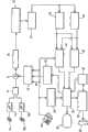
图1以方框图形式示出了根据本发明原理构建的超声诊断成像系统;Fig. 1 shows the ultrasonic diagnostic imaging system constructed according to the principles of the present invention in the form of a block diagram;
图2a和2b示出了适于用在经颅成像换能器头套中的安全头盔衬里;Figures 2a and 2b illustrate a safety helmet liner suitable for use in a transcranial imaging transducer headgear;
图3示出了根据本发明的原理对颅脑脉管系统进行超声成像并溶解血块的过程;Fig. 3 shows the process of ultrasonically imaging the cranial vasculature and dissolving blood clots according to the principles of the present invention;
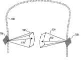
图4示出了根据本发明的三维经颅成像;Figure 4 shows a three-dimensional transcranial imaging according to the present invention;
图5示出了根据本发明的二维经颅成像;Fig. 5 shows two-dimensional transcranial imaging according to the present invention;
图6a-6d示出了根据本发明原理进行的颅脑阻塞治疗;Figures 6a-6d illustrate craniocerebral occlusion therapy in accordance with the principles of the present invention;
图7示出了根据本发明对颅脑阻塞进行超声监测的过程。Fig. 7 shows the process of ultrasonic monitoring of craniocerebral occlusion according to the present invention.
首先参照图1,以方框图形式示出了根据本发明原理构建的超声系统。提供两个换能器阵列10a和10b用于发射超声波并接收回波信息。在该示例中所示阵列是能够提供3D图像信息的二维换能器元件阵列,但是本发明的实现同样可以使用生成2D(平面)图像的二维换能器元件阵列。该换能器阵列耦合到控制所述阵列元件发射和接收信号的微型波束形成器12a和12b。微型波束形成器还能够对如美国专利5,997,479(Savord等人)、6,013,02(Savord)和6,623,42(Powers等人)中所描述的成组或“成片”的换能器元件所接收的信号进行至少部分波束形成。通过时间交错信号由多路复用器14使信号往复于微型波束形成器。所述多路复用器耦合到发射/接收(T/R)开关16,所述T/R开关16在发射和接收之间进行切换并且保护主波束形成器20避免高能量发射信号。通过耦合到T/R开关的发射控制器18对在微型波束形成器12a和12b的控制下由换能器阵列10a和10b发射的超声波束进行指引,所述发射控制器18从用户界面或控制面板38的用户操作中接收输入。Referring first to Figure 1, there is shown in block diagram form an ultrasound system constructed in accordance with the principles of the present invention. Two
将由微型波束形成器12a、12b产生的部分波束形成信号耦合到主波束形成器20,在所述主波束形成器20中将来自各个元件面片(patch)的部分波束形成信号合并成整个波束形成信号。例如,主波束形成器20可以具有128个通道,每个通道从具有12个换能器元件的面片接收部分波束形成信号。照这样,由超过1500个换能器元件的二维阵列所接收的信号能有效地促成单个波束形成信号。The partial beamformed signals produced by the mini-beamformers 12a, 12b are coupled to the
将所述波束形成信号耦合到基波/谐波信号分离器22。所述分离器22用于分离线性信号和非线性信号,从而能够识别从微泡返回的强非线性回波信号。所述分离器22能以多种方式进行操作,例如通过对基波频带和谐波频带中的接收信号进行带通滤波,或者通过称之为脉冲反向谐波分离的过程进行操作。在国际专利公布WO 2005/074805(Bruce等人)中示出并描述了合适的基波/谐波信号分离器。经分离的信号被耦合到信号处理器24,在所述信号处理器24中所述信号经受额外增强,例如斑点去除、信号复合和噪声消除。The beamforming signals are coupled to a fundamental/
经处理的信号被耦合到B模式处理器26和多普勒处理器28。B模式处理器26采用幅度检测对身体内的结构(例如肌肉、组织和血细胞)进行成像。身体结构的B模式图像可以形成谐波模式或基波模式。身体内组织和微泡均返回这两种类型的信号,而在大多数应用中微泡的谐波返回能够使微泡在图像中得到清晰地分割。多普勒处理器处理来自组织和血流的在时间上有区别的信号,用以检测包括微泡在内的图像场中物质的运动。由这些处理器产生的结构信号和运动信号被耦合到扫描转换器32和体绘制器34,所述扫描转换器32和体绘制器34产生组织结构、血流或这两个特征的组合图像的图像数据。扫描转换器将具有极坐标的回波信号转换成期望图像格式的图像信号,例如笛卡尔坐标的扇形图像。如美国专利6,530,885(Entrekin等人)中所描述的,体绘制器34将3D数据集转换成从给定参考点看去的投影3D图像。正如本文所描述的那样,当所述进行绘制的参考点变化时,3D图像可出现称之为运动视差(kinetic parallax)的旋转。这一图像操纵由用户按照用户界面38和体绘制器34之间显示控制线的指示进行控制。同样描述了不同像平面的平面图像所表示的3D体积,一种称之为多平面重组的技术。如美国专利6,723,050(Dow等人)所描述的,体绘制器34能够对直角坐标或极坐标中的图像数据进行操作。将2D或3D图像从扫描转换器和体绘制器中耦合到图像处理器30中,为在图像显示器40上显示而进一步增强、缓冲和临时保存。The processed signal is coupled to a B-
图形处理器36还被耦合到图像处理器30,所述图像处理器生成与超声图像一同显示的图形覆盖。这些图形覆盖可以含有诸如患者姓名、图像日期和时间、成像参数等的标准识别信息,并且还能产生由用户按如下所述那样导向波束矢量的图像覆盖。为此,图形处理器接收来自用户界面38的输入。用户界面还被耦合到发射控制器18以控制从换能器阵列10a和10b中生成超声信号,因此控制所述换能器阵列生成图像并施加治疗。响应用户调节而控制的发射参数包括控制所发射波峰值强度的MI(机械指数),它涉及超声的空化效应、为图像定位而对所发射的波束进行导向和/或治疗波束的定位(导向),后面还将对此进行讨论。
换能器阵列10a和10b从头部的相对两侧将超声波发射到患者的颅脑中,当然也可以或替代地采用其他位置,例如头部的前端或头颅后方枕下声窗。大多数患者头部的两侧有利地在头部每一侧耳朵周围和上方的颞骨处提供用于经颅超声的适当声窗。为了通过这些声窗发射和接收回波,所述换能器阵列必须在这些位置上处于良好的声学接触,这可通过用头套将所述换能器阵列保持抵靠在头部上而实现。例如,图2a示出了常规安全头盔200,其通过如图2b的视图中所示的头盔衬里202可调节地保持在穿戴者的头部上。所述头盔衬里牢固地包绕穿戴者的头围。在头盔衬里内如由圆环的位置204、206所指示的每一侧上定位的换能器阵列将被牢固地抵靠在穿戴者颞骨的皮肤上,从而能够使头盔衬里202用作经颅超声头套。通过可调节旋钮208将头盔衬里头套可调节地固定在适当位置。枕骨换能器将被定位在可调节旋钮208的位置处或其下方。所述头套具有一个或多个穿过头顶用于调节头套垂直位置的条带210。这些条带和头套的其他可调节构件可以是有弹性的或者可通过诸如扣环或
图3的流程图示出了根据本发明使用刚刚描述的超声系统和经颅超声头套的过程。在步骤60中,使患者穿戴所述头套,并使换能器阵列声学接触患者的皮肤。启动所述系统以便在颅脑内部进行成像,并且在步骤62中,对所述头套进行调节直到能在一个或(当双工显示时)两个换能器阵列的超声图像中看到颅脑内部的血流。此时优选使用系统的彩色血流成像模式以生成颅脑内部血流的二维或三维图像。如果在彩色血流中能够看到颅脑血流,则可以期望按需要处理该过程的其他步骤。当在超声图像中看到血流时,在步骤64中紧固所述头套以保证换能器阵列在其成像位置上。图4示出了该点上用于3D成像的情况。在该图示中,换能器阵列10a、10b保持抵靠在颅骨100的两侧,并对颅脑内部的3D图像场102、104进行成像。在多平面或体绘制3D投影中,用户将在超声系统的显示器上看到一个或两个3D图像场102、104。用户可以操纵运动视差控制以便从不同的取向观察体绘制3D图像。如美国专利5,720,291(Schwartz)中所描述的那样,用户可以调节3D图像的组织成分和血流成分的相对不透明度,从而使脑组织内部的脉管结构更好地可视化,或者可完全关闭显示器的B模式(组织)部分,而仅使3D图像场102、104内的脉管结构的血流可视化。Figure 3 is a flow chart illustrating the process of using the just described ultrasound system and transcranial ultrasound headgear in accordance with the present invention. In
当正在成功地对颅脑进行成像时,在步骤66中将微泡造影剂注入到患者的血液中。在短时间内血液中的微泡将被泵送通过颈动脉并进入颅脑脉管系统而出现在图像中。医生用户现在能够开始对阻塞脑中血管的血块进行诊断检索,从而查找脉管系统中由于局部阻塞而终止或仅被从微泡返回的回波微弱照亮的分支。当存在来自两个换能器阵列的双显示时,医生还能够比较两个显示区域的相对对称性,从而查找不对称的征象。如果医生在当前通过图像场102、104观察的脉管系统中没有发现阻塞征象,则医生可按步骤68中所指示的那样将图像场导向到所述解剖结构的其他区域。通过物理地调节换能器阵列的位置以将其的图像场瞄准通过脑部的不同解剖结构,从而可以机械地完成对图像场的导向。优选地,医生能够利用用户界面上的控制,来调节对来自换能器阵列的波束进行的导向。通过调节该控制(到发射控制器18的波束导向控制线),医生能够电子地导向颅骨内部四周的图像场,而不妨碍阵列抵靠在患者头部的声学耦合。When the brain is being successfully imaged, in step 66 a microbubble contrast agent is injected into the patient's blood. In a short time the microbubbles in the blood will be pumped through the carotid artery and into the cranial vasculature to appear in the image. Physician users are now able to initiate a diagnostic search for blood clots blocking blood vessels in the brain, looking for branches of the vasculature that have terminated due to partial blockage or are only weakly illuminated by echoes returning from microbubbles. Physicians can also compare the relative symmetry of the two display areas to look for signs of asymmetry when there are dual displays from two transducer arrays. If the physician finds no signs of obstruction in the vasculature currently viewed through the image fields 102 , 104 , the physician may direct the image fields to other areas of the anatomy as indicated in
在图像场102、104的每个位置上,医生能够在显示器上的实时图像中查找血流的梗阻,或者可以如步骤70所指示的那样捕获(抓取)颅脑脉管系统的图像或图。当采集并静态保持脉管图时,所述图像可以进行增强处理(例如,复合、信号平均)从而提高分辨率或比例尺,并能在屏幕上进行操纵及在血管阻塞的精细检索中以不同的点和不同的视角进行仔细检查。以这种方式医生能够按步骤72所指示的那样对狭窄进行诊断。如果医生检查脉管图并且没有发现血流路径中有梗阻的迹象,则医生可以将图像场导向到颅脑的另一区域,并检查另一图像场的脉管图。医生可以使用脉管图的多普勒数据或超声系统的频谱多普勒功能对颅脑脉管系统中特定点进行血流速度测量,然后使用超声系统的报告生成能力对所述测量进行记录并准备其诊断的报告。At each location in the image fields 102, 104, the physician can look for obstructions to blood flow in the live image on the display, or can capture (grab) an image or map of the cranial vasculature as indicated in
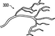
图6a-6c示出了脉管图的示例。图6a示出了血管的脉管网300。如美国专利5,474,073(Schwartz等人)中所述的那样,当仅执行血流成像并且在没有任何周围的B模式组织结构下显示血流图像时,如图6a所示的那样只示出脉管系统的血流而没有任何遮蔽的周围结构。脉管网300可以以二维、三维及通过多种多普勒技术(例如彩色血流(速度)多普勒或者功率(强度)多普勒)进行显示。在不存在狭窄时,血流网将呈现出是连续的,并且速度和强度与血管大小成比例。但是如果脉管网的分支302有梗阻,则血流将呈现出不同,例如更高的速度和/或强度,并且如果完全梗阻,则如图6c所示的那样在多普勒血流图中将完全消失。通过辨认诸如这些的特征,医生可以对狭窄做出诊断,然后如图6d所示的那样,将治疗波束110引导到怀疑有血管梗阻的位置上。Figures 6a-6c show examples of vascular maps. Figure 6a shows a
如果医生发现狭窄,则通过使狭窄部位上的微泡搅动或破碎施加治疗以努力溶解血块。医生启动“治疗”模式,并且在图像场102、104中呈现图形110、112,从而描绘治疗超声波束的矢量路径。治疗超声波束由用户界面38上的控制进行操纵,直到矢量图形110、112聚焦到阻滞部位上,如步骤74所示。治疗波束可以是紧聚焦的会聚波束,或者是称之为笔形波束的具有相对长焦距的波束。治疗波束所产生的能量可以超过诊断超声所允许的超声水平,在这种情形中血块部位上的微泡将剧烈地破碎。导致微泡破裂的能量将强烈地搅动血块,从而趋向于使血块破碎,并使其溶解在血液中。然而在一些情况中,以诊断功率水平对微泡的声照射足够溶解血块。在单次事件中,微泡可以进行振动和振荡而不是进行破碎,并且在微泡溶解之前来自这种延长振荡的能量足以使血块破碎,如步骤76所示。If a doctor finds a stricture, treatment is applied by agitating or breaking up the microbubbles on the site of the stricture in an effort to dissolve the clot. The physician activates the "therapy" mode and presents
一种对微泡进行声照射特别有效的方法被称为“闪烁”发射。在闪烁发射中,暂停声照射以使血液流动能够将大量的微泡递送到阻滞部位。在该暂停末,发射一串快速的高MI脉冲以快速并有力地使微泡破裂,这会在阻滞部位处释放能量。来自破裂微泡的气体溶解到血液中。开始另一暂停期从而能够集结新补给的微泡并使过程继续。参见美国专利5,560,364(Porter)和5,685,310(Porter)。利用随着微泡的聚集可以在低MI水平下执行成像,从而能够使医生从视觉上监测微泡的集结并判断施予高MI闪烁的最佳时间的这一发现来改进所述闪烁技术。参见美国专利6,171,246(Averkiou等人)。A particularly effective method of acoustically illuminating microbubbles is known as "scintillation" emission. In scintillation emission, acoustic irradiation is paused to allow blood flow to deliver large numbers of microbubbles to the site of block. At the end of this pause, a rapid train of high MI pulses is fired to rapidly and forcefully rupture the microbubbles, which releases energy at the site of block. Gases from the ruptured microbubbles dissolve into the blood. Another pause period begins to allow for a fresh supply of microvesicles to build up and allow the process to continue. See US Patents 5,560,364 (Porter) and 5,685,310 (Porter). The scintigraphy technique was improved by the discovery that imaging can be performed at low MI levels as the microbubbles accumulate, enabling the physician to visually monitor the microbubble accumulation and judge the optimal time to administer a high MI scintillation. See US Patent 6,171,246 (Averkiou et al.).
根据本发明的另一方面,已经发现低占空比的闪烁将在诊断超声的能量限制内产生快速微泡破坏。这样无需将患者暴露在可能造成损害的治疗性照射水平中。在该技术中,在诊断超声的MI(瞬间压力)限制内递送闪烁脉冲。超声的另一能量限制参数是空间峰值时间平均(SPTA),它是对随时间递送的平均能量的测量,并与温度升高有关。已经发现一串(诊断限制内的)高MI脉冲将使靶向微泡在100-300毫秒内破碎并溶解在血液中。这样,持续的声照射是没有效果的,因为事实上在这一时期之后没有微泡剩下。在本发明的技术中,高MI脉冲期具有50%或更少的占空比。例如,高MI脉冲可以递送200ms,之后在接下来的800msec内抑制高MI脉冲。这样高MI脉冲递送期的占空比仅为20%。多余的高MI脉冲被抑止,并且一秒间隔上递送的时间平均能量在SPTA参数的时间平均限制之内。此外,只要高MI发射停止,就能够将新的微泡回输到血块部位处。而且,在占空比的高MI部分期间可以采用更长的脉冲长度,这已经被认为对微泡的碎裂非常有效。According to another aspect of the present invention, it has been found that low duty cycle blinks will produce rapid microbubble destruction within the energy limits of diagnostic ultrasound. This eliminates the need to expose patients to potentially damaging levels of therapeutic radiation. In this technique, scintillation pulses are delivered within the MI (instantaneous pressure) limits of diagnostic ultrasound. Another energy-limiting parameter of ultrasound is spatial peak temporal averaging (SPTA), which is a measure of the average energy delivered over time and is related to temperature increase. It has been found that a train of high MI pulses (within diagnostic limits) will disrupt and dissolve targeted microbubbles in the blood within 100-300 milliseconds. Thus, continuous insonification has no effect, since virtually no microbubbles remain after this period. In the present technique, the high MI pulse period has a duty cycle of 50% or less. For example, a high MI pulse may be delivered for 200ms, followed by suppression of the high MI pulse for the next 800msec. The duty cycle of such a high MI pulse delivery period is only 20%. Unnecessary high MI pulses were suppressed, and the time-averaged energy delivered over one-second intervals was within the time-averaged limits of the SPTA parameters. Furthermore, as long as high MI emission ceases, new microbubbles can be infused back to the clot site. Also, longer pulse lengths can be employed during the high MI portion of the duty cycle, which has been found to be very effective for microbubble fragmentation.
患者遭受的脑卒中类型可能是出血性脑卒中或缺血性脑卒中。出血性卒中(其可以例如由破裂的动脉瘤所造成)导致血流出血管外,并且将不会通过微泡和超声进行治疗得到改善。此外,出血病证常常由于tPA的应用而变得更糟。由诸如血块的狭窄所造成的缺血性脑卒中是本发明实施例计划进行治疗的脑卒中类型。因此理想的是最初能够确定脑卒中病证是出血性的还是缺血性的。可以完成这一判断的一种方法是通过查找脉管系统外的血池,其表示出血病证。由于血液不是超声波的强反射体,因此在标准超声图像中血池将呈现为黑色。血池还可展现出比含有血管的血流更低的流速(多普勒速度)。在注入造影剂之后,将造影剂灌注到周围组织的微脉管系统中可以在超声图像中产生关于暗黑血池更亮对比的轻微晕圈效应。正是这些特征能够用来识别脑卒中是起源于出血性的还是缺血性的。The type of stroke a patient suffers may be a hemorrhagic stroke or an ischemic stroke. Hemorrhagic strokes (which may eg be caused by ruptured aneurysms) result in extravascular outflow and will not improve with microbubble and ultrasound treatment. In addition, bleeding disorders are often made worse by the application of tPA. Ischemic stroke caused by stenosis such as a blood clot is the type of stroke that embodiments of the present invention are intended to treat. It is therefore desirable to be able to initially determine whether the stroke syndrome is hemorrhagic or ischemic. One way this determination can be made is by looking for pools of blood outside the vasculature, which represent a bleeding disorder. Since blood is not a strong reflector of ultrasound waves, blood pools will appear black in standard ultrasound images. A blood pool may also exhibit a lower flow velocity (Doppler velocity) than blood flow containing vessels. After contrast agent injection, perfusion of the contrast agent into the microvasculature of the surrounding tissue can produce a slight halo effect in the ultrasound image with brighter contrast to the dark blood pool. It is these features that can be used to identify whether a stroke is hemorrhagic or ischemic in origin.
在图4的描绘中,看见每个图像场102、104延伸到几乎跨过颅脑的一半,这是图像场大小与期望穿过声窗处骨头的声学穿透及衰减之间的平衡。对于一些患者而言,低衰减效应能够使图像场延伸到完全跨过颅脑,从而能够使医生对颅脑对侧上的颅骨附近的脉管结构进行检查。通过交替地对两个换能器阵列的图像场进行检查,可以有效地检查跨过整个颅脑的脉管系统。有可能采集覆盖颅脑相同的中央区域但从头部相对两侧进行成像的延伸图像场。可以将这些图像相互关联并组合在一起,从而形成可以揭示脑附加特征的融合图像。治疗波束还可以从头部的两侧发射,从而能够从血块的两侧使血块破碎。并不局限于反射式超声成像,通过从一个换能器阵列发射超声并在其他换能器阵列处接收剩余的未吸收超声能量,可以执行透射成像,其可以揭示脑组织的其他特征。In the depiction of Fig. 4, each
图5示出了本发明的二维成像示例。在该示例中,换能器阵列122是执行2D成像的一维阵列。该阵列被配置成如美国专利5,226,422中所述的圆形相控阵列换能器。该换能器阵列(像本文所描述的其他阵列一样)用透镜124进行覆盖,所述透镜使患者与换能器阵列电绝缘并且在一维阵列的情形下还可以提供在高程(平面外)维度中的聚焦。换能器阵列122用声阻尼材料126进行支撑,所述声阻尼材料衰减从阵列后面发出的声波从而防止它们反射回换能器元件中。在该换能器组套后面是旋转所述阵列的图像平面140的设备130。设备130还可以是由医生抓握以便手动将圆形阵列换能器在其旋转换能器底托(未示出)中进行旋转的单个旋钮或调整片。设备130还可以是如美国专利5,181,514(Solomon等人)中所讨论的通过导体132通电以便机械地旋转所述换能器的电机。按箭头144所指示的那样旋转一维阵列换能器122将使其图像平面140围绕其中心轴枢转,从而能够为充分检查换能器阵列前的脉管系统而重新定位图像平面。如在'514患者中所讨论的,在所述阵列至少180°的旋转期间所采集的平面将占据换能器阵列前的圆锥体,其可以被绘制到该体积区域的3D图像中。该体积区域外的其他平面可以通过重新定位、相对于颅骨100在其头套中摇摆或倾斜所述换能器阵列而进行成像。如果在被成像平面的图像中发现狭窄,则医生可以导向治疗波束矢量图形142以便使所述波束瞄准该狭窄,并施加治疗脉冲以使该狭窄位置上的微泡碎裂。Figure 5 shows an example of two-dimensional imaging of the present invention. In this example, transducer array 122 is a one-dimensional array that performs 2D imaging. The array is configured as a circular phased array transducer as described in US Patent 5,226,422. This transducer array (like the others described herein) is covered with a lens 124 which electrically insulates the patient from the transducer array and which in the case of a one-dimensional array may also provide an elevation (out-of-plane) Focus in dimension. The transducer array 122 is supported with an acoustic damping material 126 that attenuates sound waves emanating from the rear of the array preventing them from being reflected back into the transducer elements. Behind the transducer stack is a device 130 for rotating the image plane 140 of the array. Device 130 may also be a single knob or tab that is grasped by the physician to manually rotate the circular array transducer in its rotating transducer mount (not shown). Device 130 may also be a motor energized through conductor 132 to mechanically rotate the transducer as discussed in US Pat. No. 5,181,514 (Solomon et al.). Rotating the one-dimensional array transducer 122 as indicated by arrow 144 pivots its image plane 140 about its central axis, enabling repositioning of the image plane for adequate inspection of the vasculature in front of the transducer array. As discussed in the '514 patient, the plane acquired during at least 180° rotation of the array will occupy a cone in front of the transducer array, which can be mapped into a 3D image of this volumetric region. Other planes outside this volumetric region can be imaged by repositioning, rocking or tilting the transducer array in its headgear relative to the
在脑卒中的情形中通常痛苦不在单次发作中表现出来,而是当心脏、肺部或血管中的血块或梗阻逐渐破碎、从而随时间将小血块相继释放到颅脑脉管系统地在重复发作中表现出来。这样,遭受初始脑卒中事件后依然活着的患者在不远的将来可能会处于其他事件的风险。因此,理想的是在出现初始脑卒中事件之后监测这些患者一段时间,以便在复发时可以立即进行治疗。根据本发明的另一方面,本发明的实施例可以用于监测脑卒中受害者的复发事件。可以将换能器阵列10a、10b、微型波束形成器12a、12b以及多路复用器14有效地作为头套的一部分封装在倒装芯片结构中。这些部件可以由电池供电并且多路复用器的输出被连接到r.f发射器。如图4所示的那样对固定图像场102、104进行连续成像;在该实施例中不一定能够导向或重定位所述图像场。如美国专利6,113,547(Catallo等人)中所描述的那样,将微型波束形成器12a、12b生成的图像数据无线发射到基本单元。在该基站中,如果需要可以执行附加的波束形成以及图1系统的图像处理和显示功能。如果患者是固定不动的,则无线连接并非是必须的,也可以采用与所述基站的有线连接。当所述头套由对该设备具有最少经验的个体进行应用时,所述无线连接同样是有用的。例如,第一急救者可能不能确保所述头套被正确应用并且正在采集关于患者脉管系统满意的图像数据集。在这种情形下,可以将所述图像发射到基站、医院或者其中有经验的人员能够实时观看所述图像并告诉该第一急救者如何将所述头套成功应用在患者身上的其他地方。In the case of a stroke usually the pain is not manifested in a single attack, but is repeated over time as a blood clot or blockage in the heart, lungs, or blood vessels gradually breaks up, releasing small blood clots sequentially into the brain's vasculature manifested during seizures. Thus, patients who survive an initial stroke event may be at risk for additional events in the near future. Therefore, it is ideal to monitor these patients for a period of time after the initial stroke event so that immediate treatment can be initiated in the event of relapse. According to another aspect of the invention, embodiments of the invention may be used to monitor stroke victims for recurrent events. The
在本实例中,图像显示器对于监测应用而言并非是必须的。当在基站形成脉管系统的连续图像时,将它们存储在图像存储器52中,并比较时间上不同的图像以便通过运行血流变化检测器50来检测脉管系统的血流变化。血流变化检测器运行以比较时间上不同的图像的相同性质,类似于如美国专利6,442,289(Olsson等人)中描述的那样用于通过图像处理识别运动的图像数据校正技术。只要连续的图像和分隔开更大时间间隔的图像在其流动特征中表现为基本相同,例如在脉管系统的特定段的流动特征中没有局部变化,并且脉管系统中没有任何段已经停止返回指示血流持续的多普勒信号,则血流变化检测器50将在没有变化的情况下继续其对脉管系统进行监测。例如,所述脉管系统在长时间内可以表现为图6a的脉管网300,而突然可能检测不到一段的血流,如图6c中通过缺失的血管302所示出的那样。如果血流变化检测器50检测到血流变化(例如上面所示的其中一种),则启动报警器,例如位于护士站的声响报警器42。然后可以立即为患者提供医疗救助。另外,医务人员可以对在检测到血流变化时图像存储器中存储的图像进行检查,以准确辨明检测到的梗阻出现在脉管系统中的什么位置。然后将治疗明确地引导到梗阻部位,而无需对一系列脉管图进行仔细地检查。In this example, an image display is not necessary for the monitoring application. As successive images of the vasculature are formed at the base station, they are stored in the
由于这是监测应用,因此不必以实时成像所必须的高速率进行图像采集。例如可以每秒或以更大的图像采集间隔来采集新的图像。较低的采集速率有助于在使用r.f.链路的行走(ambulatory)实现中节约电池功率。较低的成像速率还允许同一系统以时间交错的方式处理来自多名患者的图像,这对于需要监测多名患者的护士站而言是非常有用的。Since this is a monitoring application, it is not necessary to acquire images at the high rates necessary for real-time imaging. For example, new images may be acquired every second or at greater image acquisition intervals. A lower acquisition rate helps save battery power in ambulatory implementations using r.f. links. The lower imaging rate also allows the same system to process images from multiple patients in a time-staggered fashion, which is useful in nursing stations where multiple patients need to be monitored.
在长期监测或对行走患者的监测期间,头套有可能相对于患者的头部发生移动,从而造成来自已经移动的换能器10a、10b的连续图像之间存在差异。这种移动同样造成被监测的特定解剖区域移动到换能器阵列10a或10b的图像场之外。虽然可以将血流变化检测器50设计成不受这种全局变化的影响而只查找血流中的局部变化,但理想的是能够警告医务人员重新调节头套或重新采集图像场中的靶向解剖结构。这在图1的实施例中是借助于图像场控制器54来完成的,所述图像场控制器对时间上不同的图像执行图像分析,以检测图像数据的全局对准变化。如果头套在连续图像之间未发生移动,则(例如)每个换能器阵列的连续图像将是相同的,并且各图像的图像数据将展现出高度的相关性。例如,在美国专利5,556,674(Weng)、6,572,549(Jong等人)或6,589,176(Jago等人)中用于测量图像对准的图像分析技术和其他技术可以用于执行图像比较。头套的移动将导致相关性的全局变化,这会警告医务人员调节头套。相关性的局部变化可能是本应由血流变化检测器50检测的局部血流变化,或者可以使用局部去相关来警告医务人员核查患者状况。另一可能性是将全局相关矢量用作图像相对于图像发生运动的指示。然后,如以前面提到的美国专利6,589,176中讨论的图像稳定方式那样,发射控制器18使用所述运动变化来调节对图像场102、104、140的波束的导向,从而将所述解剖结构重新定位在新采集的图像场中的相同位置。这将能够使系统最初监测的解剖结构不管头套定位中是否有小的变化而保持在视野和图像数据集中。如果靶向解剖结构移出波束导向重新采集的范围,则为医务人员发出警告以重新定位头套。类似地,可以使用这种在存在运动时重新导向校正来保持治疗笔形波束110、112稳定地指向正被处理的靶向血块。During long-term monitoring or monitoring of a walking patient, it is possible for the headgear to move relative to the patient's head, causing discrepancies between successive images from
图7的流程图示出了本发明监测实现的典型顺序。在步骤60中将具有阵列换能器的头套戴在患者上,并在步骤62中初始显示和回顾各图像直到对头套进行调节使得在各图像中可以观察到血流为止。在步骤64中,当确定正在采集颅脑血流的图像时,不再需要图像显示器并将头套紧固在患者头上的适当位置。在步骤80中,从阵列的图像场中定期采集图像数据并将其发射到监测单元。在步骤82中,于监测单元处,可以按照需要对图像数据作进一步处理,然后在步骤84中,将新的图像与一个或多个先前采集的图像进行比较。如果图像的流动特征没有变化,则继续进行图像数据的定期发射、接收和比较。但是如果新的图像不同于预定的流动特征,则在步骤86中检测血流变化,并在88中发出警告以引起医护注意。The flow chart of Figure 7 shows a typical sequence for the monitoring implementation of the present invention. A headgear with the array transducer is donned on the patient in
虽然监测实现可以用2D(平面)成像来执行,但是优选地使用3D成像,以便可以监测更大的体积区域。监测可以只用一个换能器阵列来执行,但是更大数量的阵列同样提供对更大颅脑区域的监测。While monitoring implementations can be performed with 2D (planar) imaging, it is preferred to use 3D imaging so that larger volumetric areas can be monitored. Monitoring can be performed with only one transducer array, but larger numbers of arrays also provide monitoring of larger brain regions.
Claims (20)
Applications Claiming Priority (3)
| Application Number | Priority Date | Filing Date | Title |
|---|---|---|---|
| US82210606P | 2006-08-11 | 2006-08-11 | |
| US60/822,106 | 2006-08-11 | ||
| PCT/IB2007/053073WO2008017997A2 (en) | 2006-08-11 | 2007-08-03 | Ultrasound system for cerebral blood flow imaging and microbubble-enhanced blood clot lysis |
Publications (2)
| Publication Number | Publication Date |
|---|---|
| CN101500650Atrue CN101500650A (en) | 2009-08-05 |
| CN101500650B CN101500650B (en) | 2012-08-08 |
Family
ID=39030023
Family Applications (1)
| Application Number | Title | Priority Date | Filing Date |
|---|---|---|---|
| CN200780029775XAExpired - Fee RelatedCN101500650B (en) | 2006-08-11 | 2007-08-03 | Ultrasound system for brain blood flow imaging and microbubble-enhanced clot lysis |
Country Status (5)
| Country | Link |
|---|---|
| US (2) | US9630028B2 (en) |
| EP (1) | EP2051777B1 (en) |
| JP (2) | JP5450065B2 (en) |
| CN (1) | CN101500650B (en) |
| WO (1) | WO2008017997A2 (en) |
Cited By (9)
| Publication number | Priority date | Publication date | Assignee | Title |
|---|---|---|---|---|
| CN101919710A (en)* | 2010-09-17 | 2010-12-22 | 天津大学 | Medical Ultrasound Imager |
| CN104736068A (en)* | 2012-10-19 | 2015-06-24 | 皇家飞利浦有限公司 | Ultrasound head frame for emergency medical services |
| CN104887185A (en)* | 2015-06-12 | 2015-09-09 | 冯明臣 | Treatment device for severe brain patients |
| CN102667852B (en)* | 2009-11-25 | 2015-11-25 | 皇家飞利浦电子股份有限公司 | Strengthen view data/dosage to reduce |
| CN106999149A (en)* | 2014-11-25 | 2017-08-01 | 皇家飞利浦有限公司 | Multisensor ultrasonic probe and correlation technique |
| CN107692974A (en)* | 2017-10-25 | 2018-02-16 | 上海交通大学 | A kind of multi-parameter animal cortex blood flow monitoring device and method |
| CN108852414A (en)* | 2018-05-07 | 2018-11-23 | 深圳市德力凯医疗设备股份有限公司 | It is a kind of through cranium three-dimensional Angiography-Comparative and system |
| CN111529970A (en)* | 2020-04-20 | 2020-08-14 | 内江师范学院 | A head-mounted multi-channel ultrasonic nerve stimulation device and method |
| CN114098816A (en)* | 2021-11-05 | 2022-03-01 | 西安交通大学 | Quantitative classification and imaging method of microbubble perfusion function in small arteriolar/venous vessels in the brain by ultrasound |
Families Citing this family (57)
| Publication number | Priority date | Publication date | Assignee | Title |
|---|---|---|---|---|
| EP1647232B1 (en) | 2001-12-03 | 2011-08-17 | Ekos Corporation | Catheter with multiple ultrasound radiating members |
| EP2051777B1 (en)* | 2006-08-11 | 2019-01-16 | Koninklijke Philips N.V. | Ultrasound system for cerebral blood flow imaging and microbubble-enhanced blood clot lysis |
| US20100041989A1 (en)* | 2006-09-29 | 2010-02-18 | The Trustees Of The University Of Pennsylvania | Use of ultrasound as an antivascular agent |
| US10182833B2 (en) | 2007-01-08 | 2019-01-22 | Ekos Corporation | Power parameters for ultrasonic catheter |
| EP2170181B1 (en) | 2007-06-22 | 2014-04-16 | Ekos Corporation | Method and apparatus for treatment of intracranial hemorrhages |
| US20100210940A1 (en)* | 2008-11-14 | 2010-08-19 | Hoag Memorial Hospital Presbyterian | CT-Guided Focused Ultrasound for Stroke Treatment |
| WO2010103469A1 (en) | 2009-03-12 | 2010-09-16 | Koninklijke Philips Electronics, N.V. | Sonolysis of blood clots using low power, coded excitation pulses |
| WO2010118307A1 (en)* | 2009-04-09 | 2010-10-14 | The Trustees Of The University Of Pennsylvania | Methods and systems for image-guided treatment of blood vessels |
| US20120165670A1 (en)* | 2009-09-03 | 2012-06-28 | Koninklijke Philips Electronics N.V. | Contralateral array based correction of transcranial ultrasound aberration |
| JP6291253B2 (en) | 2010-08-27 | 2018-03-14 | イーコス・コーポレイシヨン | Ultrasound catheter |
| WO2012042423A1 (en) | 2010-09-30 | 2012-04-05 | Koninklijke Philips Electronics N.V. | Monitoring and control of microbubble cavitation in therapeutic ultrasound |
| JP6099865B2 (en)* | 2011-01-11 | 2017-03-22 | 東芝メディカルシステムズ株式会社 | Diagnostic imaging equipment |
| HK1205025A1 (en)* | 2012-05-11 | 2015-12-11 | 加利福尼亚大学董事会 | Portable device to initiate and monitor treatment of stroke victims in the field |
| US10413278B2 (en) | 2012-06-28 | 2019-09-17 | University of Pittsburgh—of the Commonwealth System of Higher Education | Methods and devices for ultrasound contrast-assisted therapy |
| US10420532B2 (en) | 2013-01-23 | 2019-09-24 | Brainlab Ag | Method and apparatus for calculating the contact position of an ultrasound probe on a head |
| WO2014159274A1 (en) | 2013-03-14 | 2014-10-02 | Ekos Corporation | Method and apparatus for drug delivery to a target site |
| WO2015073903A1 (en)* | 2013-11-15 | 2015-05-21 | Neural Analytics Inc. | Monitoring structural features of cerebral blood flow velocity for diagnosis of neurological conditions |
| WO2014207665A2 (en) | 2013-06-28 | 2014-12-31 | Koninklijke Philips N.V. | Transducer placement and registration for image-guided sonothrombolysis |
| CA2917095C (en) | 2013-07-03 | 2021-11-02 | Bracco Suisse S.A. | Devices and methods for the ultrasound treatment of ischemic stroke |
| US20160278736A1 (en)* | 2013-11-15 | 2016-09-29 | Neural Analytics Inc. | Monitoring structural features of cerebral blood flow velocity for diagnosis of neurological conditions |
| WO2015075603A1 (en) | 2013-11-21 | 2015-05-28 | Koninklijke Philips N.V. | Ultrasound headset |
| WO2015092604A1 (en) | 2013-12-18 | 2015-06-25 | Koninklijke Philips N.V. | System and method for ultrasound and computed tomography image registration for sonothrombolysis treatment |
| US20150374334A1 (en)* | 2014-01-08 | 2015-12-31 | QT Ultrasound LLC | Quantitative transmission ultrasound imaging of dense anatomical structures |
| WO2016075586A1 (en)* | 2014-11-14 | 2016-05-19 | Koninklijke Philips N.V. | Ultrasound device for sonothrombolysis therapy |
| WO2016092414A1 (en) | 2014-12-11 | 2016-06-16 | Koninklijke Philips N.V. | Microbubble signal based temporal-bone thickness compensation for sonothrombolysis |
| WO2016097867A2 (en) | 2014-12-19 | 2016-06-23 | Université Pierre Et Marie Curie (Paris 6) | Implantable ultrasound generating treating device for brain treatment, apparatus comprising such device and method implementing such device |
| CN107530555A (en) | 2015-03-30 | 2018-01-02 | 皇家飞利浦有限公司 | The ultrasound transducer array disposed and monitored for ultrasound thrombolysis |
| CN107708581B (en) | 2015-06-10 | 2021-11-19 | Ekos公司 | Ultrasonic wave guide tube |
| CN107635472A (en) | 2015-06-19 | 2018-01-26 | 神经系统分析公司 | Transcranial doppler detector |
| EP3316927B1 (en) | 2015-06-30 | 2020-03-25 | Koninklijke Philips N.V. | Infusion system and method for sonothrombolysis stroke treatment |
| CN104984701B (en)* | 2015-07-13 | 2017-06-27 | 中国科学院声学研究所 | A kind of cavitation cloud microbubble preparation device and method thereof |
| CN105193449A (en)* | 2015-10-14 | 2015-12-30 | 苏州斯科特医学影像科技有限公司 | Application of three-dimensional ultrasound in hystero-salpingography |
| CN105286915A (en)* | 2015-10-14 | 2016-02-03 | 苏州斯科特医学影像科技有限公司 | Head temporal bone imaging method in combination with phased array probe |
| CN105147331A (en)* | 2015-10-14 | 2015-12-16 | 苏州斯科特医学影像科技有限公司 | Application of three-dimensional ultrasound in artificial abortion |
| WO2017120361A1 (en) | 2016-01-05 | 2017-07-13 | Neural Analytics, Inc. | Integrated probe structure |
| CN108778140A (en) | 2016-01-05 | 2018-11-09 | 神经系统分析公司 | Systems and methods for determining clinical indications |
| US11589836B2 (en)* | 2016-01-05 | 2023-02-28 | Novasignal Corp. | Systems and methods for detecting neurological conditions |
| AU2017222925B2 (en) | 2016-02-23 | 2021-11-04 | Sunnybrook Research Institute | Patient-specific headset for diagnostic and therapeutic transcranial procedures |
| US11253729B2 (en) | 2016-03-11 | 2022-02-22 | Sorbonne Universite | External ultrasound generating treating device for spinal cord and/or spinal nerve treatment, apparatus comprising such device and method |
| WO2017153798A1 (en) | 2016-03-11 | 2017-09-14 | Université Pierre Et Marie Curie (Paris 6) | Implantable ultrasound generating treating device for spinal cord and/or spinal nerve treatment, apparatus comprising such device and method |
| US20200405258A1 (en)* | 2016-07-15 | 2020-12-31 | The University Of North Carolina At Chapel Hill | Methods and systems for using phase change nanodroplets to enhance sonothrombolysis |
| WO2018026738A1 (en)* | 2016-08-01 | 2018-02-08 | Bhaskar Ramamurthy | Ultrasound guided opening of blood-brain barrier |
| EP3554348B1 (en) | 2016-12-14 | 2022-07-06 | The Regents of The University of California | Cerebral blood flow reorganization |
| US11259781B2 (en) | 2016-12-16 | 2022-03-01 | Koninklijke Philips N.V. | Adaptive pulsing for sonothrombolysis treatment |
| EP3600062B1 (en)* | 2017-03-24 | 2025-07-16 | Burl Concepts, Inc. | Portable ultrasound device |
| CN112165902A (en)* | 2018-06-07 | 2021-01-01 | Y·陆 | Apparatus and method for diagnosing vascular occlusion |
| WO2020041021A1 (en) | 2018-08-22 | 2020-02-27 | First-Light Usa, Llc | Head-worn remote informatics system |
| US12105052B2 (en) | 2018-11-09 | 2024-10-01 | Georgia Tech Research Corporation | Systems and methods for ultrasound imaging and focusing |
| US11793863B2 (en) | 2019-04-26 | 2023-10-24 | University of Pittsburgh—of the Commonwealth System of Higher Education | Functionalized microbubble embodiments for ultrasound-mediated treatment and methods of making and using the same |
| US12186593B2 (en)* | 2019-06-07 | 2025-01-07 | The Board Of Trustees Of The Leland Stanford Junior University | Pattern interference radiation force (PIRF) neural stimulators |
| EP3782543A1 (en) | 2019-08-21 | 2021-02-24 | Artedrone | Method and system for determining properties in a vessel |
| GB202100450D0 (en)* | 2021-01-14 | 2021-03-03 | Ucl Business Plc | Transcranial ultrasound devices and methods |
| US20220287733A1 (en)* | 2021-03-15 | 2022-09-15 | Covidien Lp | Devices, systems, and methods for disrupting obstructions in body lumens |
| US20240268791A1 (en)* | 2021-06-04 | 2024-08-15 | Sorbonne Universite | Portable imaging system |
| US20250176937A1 (en)* | 2021-08-27 | 2025-06-05 | National Institute Of Advanced Industrial Science And Technology | Ultrasonic device, head holder, and method for processing ultrasonic signals |
| EP4410188A1 (en)* | 2023-02-03 | 2024-08-07 | Stryker Corporation | Monitoring arterial and venous blood flow during treatments |
| US20250161718A1 (en)* | 2023-11-21 | 2025-05-22 | Sanmai Technologies, PBC | Wearable closed loop tus system |
Family Cites Families (64)
| Publication number | Priority date | Publication date | Assignee | Title |
|---|---|---|---|---|
| US6088613A (en)* | 1989-12-22 | 2000-07-11 | Imarx Pharmaceutical Corp. | Method of magnetic resonance focused surgical and therapeutic ultrasound |
| DE4302538C1 (en)* | 1993-01-29 | 1994-04-07 | Siemens Ag | Ultrasonic therapy device for tumour treatment lithotripsy or osteorestoration - with ultrasonic imaging and ultrasonic treatment modes using respective acoustic wave frequencies |
| DE4302537C1 (en)* | 1993-01-29 | 1994-04-28 | Siemens Ag | Ultrasound imaging and therapy device - generates imaging waves and focussed treatment waves having two differing frequencies for location and treatment of e.g tumours |
| JPH07204202A (en)* | 1994-01-26 | 1995-08-08 | Toshiba Corp | Ultrasonic therapy equipment |
| JPH08164135A (en)* | 1994-10-03 | 1996-06-25 | Hitachi Medical Corp | Heavy duty ultrasonic beam irradiation method and ultrasonic wave irradiation treatment device used in the same |
| US5474073A (en)* | 1994-11-22 | 1995-12-12 | Advanced Technology Laboratories, Inc. | Ultrasonic diagnostic scanning for three dimensional display |
| US5558092A (en)* | 1995-06-06 | 1996-09-24 | Imarx Pharmaceutical Corp. | Methods and apparatus for performing diagnostic and therapeutic ultrasound simultaneously |
| US5827204A (en)* | 1996-11-26 | 1998-10-27 | Grandia; Willem | Medical noninvasive operations using focused modulated high power ultrasound |
| JPH10328189A (en)* | 1997-05-29 | 1998-12-15 | Matsushita Electric Ind Co Ltd | Ultrasound blood flow measurement device |
| US6013032A (en)* | 1998-03-13 | 2000-01-11 | Hewlett-Packard Company | Beamforming methods and apparatus for three-dimensional ultrasound imaging using two-dimensional transducer array |
| US5997479A (en)* | 1998-05-28 | 1999-12-07 | Hewlett-Packard Company | Phased array acoustic systems with intra-group processors |
| US7686763B2 (en)* | 1998-09-18 | 2010-03-30 | University Of Washington | Use of contrast agents to increase the effectiveness of high intensity focused ultrasound therapy |
| US6196972B1 (en)* | 1998-11-11 | 2001-03-06 | Spentech, Inc. | Doppler ultrasound method and apparatus for monitoring blood flow |
| US6524249B2 (en)* | 1998-11-11 | 2003-02-25 | Spentech, Inc. | Doppler ultrasound method and apparatus for monitoring blood flow and detecting emboli |
| US6113547A (en)* | 1998-11-20 | 2000-09-05 | Atl Ultrasound, Inc. | Ultrasonic diagnostic imaging with cordless scanhead transmission system |
| JP2000189521A (en)* | 1998-12-28 | 2000-07-11 | Toshiba Corp | Ultrasound diagnostic and treatment equipment |
| US6171246B1 (en)* | 1999-04-29 | 2001-01-09 | Michalakis Averkiou | Realtime ultrasonic imaging of perfusion using ultrasonic contrast agents |
| US7534209B2 (en)* | 2000-05-26 | 2009-05-19 | Physiosonics, Inc. | Device and method for mapping and tracking blood flow and determining parameters of blood flow |
| US6682483B1 (en)* | 1999-05-28 | 2004-01-27 | Vuesonix Sensors, Inc. | Device and method for mapping and tracking blood flow and determining parameters of blood flow |
| US7399279B2 (en)* | 1999-05-28 | 2008-07-15 | Physiosonics, Inc | Transmitter patterns for multi beam reception |
| US7238158B2 (en)* | 1999-05-28 | 2007-07-03 | Allez Physionix, Ltd. | Pulse interleaving in doppler ultrasound imaging |
| US6299579B1 (en)* | 1999-06-30 | 2001-10-09 | Atl Ultrasound | Extended field of view ultrasonic diagnostic imaging with image reacquisition |
| US6887199B2 (en)* | 1999-09-23 | 2005-05-03 | Active Signal Technologies, Inc. | Brain assessment monitor |
| AU1579901A (en)* | 1999-11-01 | 2001-05-14 | University Of Cincinnati, The | Transcranial ultrasound thrombolysis system and method of treating a stroke |
| US7037267B1 (en)* | 1999-11-10 | 2006-05-02 | David Lipson | Medical diagnostic methods, systems, and related equipment |
| US6635017B1 (en)* | 2000-02-09 | 2003-10-21 | Spentech, Inc. | Method and apparatus combining diagnostic ultrasound with therapeutic ultrasound to enhance thrombolysis |
| US6428477B1 (en)* | 2000-03-10 | 2002-08-06 | Koninklijke Philips Electronics, N.V. | Delivery of theraputic ultrasound by two dimensional ultrasound array |
| US6468219B1 (en)* | 2000-04-24 | 2002-10-22 | Philip Chidi Njemanze | Implantable telemetric transcranial doppler device |
| US6503202B1 (en)* | 2000-06-29 | 2003-01-07 | Acuson Corp. | Medical diagnostic ultrasound system and method for flow analysis |
| US6733450B1 (en)* | 2000-07-27 | 2004-05-11 | Texas Systems, Board Of Regents | Therapeutic methods and apparatus for use of sonication to enhance perfusion of tissue |
| US6468216B1 (en)* | 2000-08-24 | 2002-10-22 | Kininklijke Philips Electronics N.V. | Ultrasonic diagnostic imaging of the coronary arteries |
| US6612988B2 (en)* | 2000-08-29 | 2003-09-02 | Brigham And Women's Hospital, Inc. | Ultrasound therapy |
| US7604599B2 (en)* | 2000-09-29 | 2009-10-20 | New Health Sciences, Inc. | Systems and methods for using dynamic vascular assessment to improve vascular stent placement, application, design and marketing |
| US20070016046A1 (en)* | 2000-09-29 | 2007-01-18 | New Health Sciences, Inc. | Systems and methods for using dynamic vascular assessment to distinguish among vascular states and for investigating intracranial pressure |
| US7547283B2 (en)* | 2000-11-28 | 2009-06-16 | Physiosonics, Inc. | Methods for determining intracranial pressure non-invasively |
| US20040220474A1 (en)* | 2002-03-20 | 2004-11-04 | Kenneth Abend | Determining the power of an ultrasound reflection using an autocorrelation technique |
| US20040049134A1 (en) | 2002-07-02 | 2004-03-11 | Tosaya Carol A. | System and methods for treatment of alzheimer's and other deposition-related disorders of the brain |
| JP4387947B2 (en)* | 2002-08-29 | 2009-12-24 | 株式会社東京大学Tlo | Ultrasonic therapy device |
| WO2004066856A1 (en)* | 2003-01-31 | 2004-08-12 | Hitachi Medical Corporation | Ultrasonic probe and ultrasonic device |
| CN100356895C (en)* | 2003-01-31 | 2007-12-26 | 株式会社日立医药 | Ultrasonic probe and ultrasonic device |
| US7175599B2 (en)* | 2003-04-17 | 2007-02-13 | Brigham And Women's Hospital, Inc. | Shear mode diagnostic ultrasound |
| US7344509B2 (en)* | 2003-04-17 | 2008-03-18 | Kullervo Hynynen | Shear mode therapeutic ultrasound |
| US7128713B2 (en)* | 2003-07-10 | 2006-10-31 | Spentech, Inc. | Doppler ultrasound method and apparatus for monitoring blood flow and hemodynamics |
| US7206257B1 (en)* | 2003-09-02 | 2007-04-17 | The United States Of America Represented By The Secretary Of The Navy | Acoustic remote caviation as a destruction device |
| PL1663394T3 (en)* | 2003-09-08 | 2014-10-31 | Univ Arkansas | Ultrasound apparatus for augmented clot lysis |
| JP4263575B2 (en)* | 2003-10-02 | 2009-05-13 | 株式会社日立メディコ | Ultrasonic transmitter and ultrasonic apparatus using the same |
| JP2005124920A (en)* | 2003-10-24 | 2005-05-19 | Olympus Corp | Ultrasonic diagnostic treatment equipment |
| US7896821B1 (en)* | 2003-11-14 | 2011-03-01 | Perfusion Technology, LLC | Low intensity directed ultrasound (LODUS) mediated blood brain barrier disruption |
| AU2004320514B8 (en)* | 2004-06-04 | 2009-08-27 | Acusphere, Inc. | Ultrasound contrast agent dosage formulation |
| EP1774920A4 (en)* | 2004-06-21 | 2011-01-05 | Hiroshi Furuhata | Ultrasonic brain infarction treating device |
| JP2006136441A (en)* | 2004-11-11 | 2006-06-01 | Toshiba Corp | Ultrasonic irradiation apparatus and ultrasonic irradiation method |
| US20060184070A1 (en)* | 2004-11-12 | 2006-08-17 | Hansmann Douglas R | External ultrasonic therapy |
| US7857763B2 (en)* | 2005-02-08 | 2010-12-28 | Alan Chi-Chung Tai | Automatic signal-optimizing transducer assembly for blood flow measurement |
| US8162837B2 (en)* | 2005-06-13 | 2012-04-24 | Spentech, Inc. | Medical doppler ultrasound system for locating and tracking blood flow |
| US7717853B2 (en)* | 2005-06-24 | 2010-05-18 | Henry Nita | Methods and apparatus for intracranial ultrasound delivery |
| US20070016040A1 (en)* | 2005-06-24 | 2007-01-18 | Henry Nita | Methods and apparatus for intracranial ultrasound delivery |
| US20070129652A1 (en)* | 2005-11-15 | 2007-06-07 | Henry Nita | Methods and apparatus for intracranial ultrasound therapies |
| US8057408B2 (en)* | 2005-09-22 | 2011-11-15 | The Regents Of The University Of Michigan | Pulsed cavitational ultrasound therapy |
| US20070083120A1 (en)* | 2005-09-22 | 2007-04-12 | Cain Charles A | Pulsed cavitational ultrasound therapy |
| US20080262350A1 (en)* | 2005-11-18 | 2008-10-23 | Imarx Therapeutics, Inc. | Ultrasound Apparatus and Method to Treat an Ischemic Stroke |
| WO2008018054A2 (en)* | 2006-08-08 | 2008-02-14 | Keter Medical Ltd. | Imaging system |
| CN101500651B (en)* | 2006-08-11 | 2012-08-08 | 皇家飞利浦电子股份有限公司 | Ultrasound system for brain blood flow imaging and microbubble-enhanced clot lysis |
| EP2051777B1 (en)* | 2006-08-11 | 2019-01-16 | Koninklijke Philips N.V. | Ultrasound system for cerebral blood flow imaging and microbubble-enhanced blood clot lysis |
| CA2917095C (en)* | 2013-07-03 | 2021-11-02 | Bracco Suisse S.A. | Devices and methods for the ultrasound treatment of ischemic stroke |
- 2007
- 2007-08-03EPEP07825989.2Apatent/EP2051777B1/ennot_activeNot-in-force
- 2007-08-03USUS12/376,317patent/US9630028B2/ennot_activeExpired - Fee Related
- 2007-08-03CNCN200780029775XApatent/CN101500650B/ennot_activeExpired - Fee Related
- 2007-08-03JPJP2009523403Apatent/JP5450065B2/ennot_activeExpired - Fee Related
- 2007-08-03WOPCT/IB2007/053073patent/WO2008017997A2/enactiveApplication Filing
- 2013
- 2013-08-14JPJP2013168503Apatent/JP5684870B2/ennot_activeExpired - Fee Related
- 2017
- 2017-03-24USUS15/468,256patent/US10363012B2/ennot_activeExpired - Fee Related
Cited By (11)
| Publication number | Priority date | Publication date | Assignee | Title |
|---|---|---|---|---|
| CN102667852B (en)* | 2009-11-25 | 2015-11-25 | 皇家飞利浦电子股份有限公司 | Strengthen view data/dosage to reduce |
| CN101919710A (en)* | 2010-09-17 | 2010-12-22 | 天津大学 | Medical Ultrasound Imager |
| CN104736068A (en)* | 2012-10-19 | 2015-06-24 | 皇家飞利浦有限公司 | Ultrasound head frame for emergency medical services |
| CN106999149A (en)* | 2014-11-25 | 2017-08-01 | 皇家飞利浦有限公司 | Multisensor ultrasonic probe and correlation technique |
| CN106999149B (en)* | 2014-11-25 | 2020-09-29 | 皇家飞利浦有限公司 | Multi-sensor ultrasound probe and related methods |
| CN104887185A (en)* | 2015-06-12 | 2015-09-09 | 冯明臣 | Treatment device for severe brain patients |
| CN107692974A (en)* | 2017-10-25 | 2018-02-16 | 上海交通大学 | A kind of multi-parameter animal cortex blood flow monitoring device and method |
| CN108852414A (en)* | 2018-05-07 | 2018-11-23 | 深圳市德力凯医疗设备股份有限公司 | It is a kind of through cranium three-dimensional Angiography-Comparative and system |
| CN111529970A (en)* | 2020-04-20 | 2020-08-14 | 内江师范学院 | A head-mounted multi-channel ultrasonic nerve stimulation device and method |
| CN114098816A (en)* | 2021-11-05 | 2022-03-01 | 西安交通大学 | Quantitative classification and imaging method of microbubble perfusion function in small arteriolar/venous vessels in the brain by ultrasound |
| CN114098816B (en)* | 2021-11-05 | 2024-08-20 | 西安交通大学 | Quantitative classification imaging method for small micro-motion/venous vessel micro-bubble contrast perfusion function in ultrasonic brain |
Also Published As
| Publication number | Publication date |
|---|---|
| US10363012B2 (en) | 2019-07-30 |
| EP2051777B1 (en) | 2019-01-16 |
| JP2010500084A (en) | 2010-01-07 |
| WO2008017997A3 (en) | 2008-05-08 |
| EP2051777A2 (en) | 2009-04-29 |
| US9630028B2 (en) | 2017-04-25 |
| US20100160779A1 (en) | 2010-06-24 |
| JP5684870B2 (en) | 2015-03-18 |
| CN101500650B (en) | 2012-08-08 |
| US20170196465A1 (en) | 2017-07-13 |
| JP5450065B2 (en) | 2014-03-26 |
| WO2008017997A2 (en) | 2008-02-14 |
| JP2014000431A (en) | 2014-01-09 |
Similar Documents
| Publication | Publication Date | Title |
|---|---|---|
| CN101500650B (en) | Ultrasound system for brain blood flow imaging and microbubble-enhanced clot lysis | |
| CN101500651B (en) | Ultrasound system for brain blood flow imaging and microbubble-enhanced clot lysis | |
| JP6943768B2 (en) | Ultrasonic Transducer Array for Ultrasound Thrombosis Treatment and Monitoring | |
| Baron et al. | Simulation of intracranial acoustic fields in clinical trials of sonothrombolysis | |
| JP5451819B2 (en) | Method of using combined imaging and therapy transducers to dissolve clots | |
| WO2012042423A1 (en) | Monitoring and control of microbubble cavitation in therapeutic ultrasound | |
| JP2017500943A (en) | System and method for registration of ultrasound and computed tomography images for ultrasonic thrombolysis procedures | |
| JP2002516586A (en) | Method and apparatus for providing acoustic hemostasis | |
| JP2008539908A (en) | Ultrasound diagnostic and treatment equipment | |
| WO2004066856A1 (en) | Ultrasonic probe and ultrasonic device | |
| US20190329075A1 (en) | Ultrasonic sonothrombolysis treatment planning | |
| EP3554378B1 (en) | Ultrasonic transducer array monitoring during transcranial ultrasound procedures | |
| US20190069875A1 (en) | Ultrasound system for cerebral blood flow imaging and microbubble-enhanced blood clot lysis |
Legal Events
| Date | Code | Title | Description |
|---|---|---|---|
| C06 | Publication | ||
| PB01 | Publication | ||
| C10 | Entry into substantive examination | ||
| SE01 | Entry into force of request for substantive examination | ||
| C14 | Grant of patent or utility model | ||
| GR01 | Patent grant | ||
| CF01 | Termination of patent right due to non-payment of annual fee | ||
| CF01 | Termination of patent right due to non-payment of annual fee | Granted publication date:20120808 |