CN101500495B - Suture for wound closure, tissue approximation, tissue support, suspension and/or fixation - Google Patents
Suture for wound closure, tissue approximation, tissue support, suspension and/or fixationDownload PDFInfo
- Publication number
- CN101500495B CN101500495BCN2007800293496ACN200780029349ACN101500495BCN 101500495 BCN101500495 BCN 101500495BCN 2007800293496 ACN2007800293496 ACN 2007800293496ACN 200780029349 ACN200780029349 ACN 200780029349ACN 101500495 BCN101500495 BCN 101500495B
- Authority
- CN
- China
- Prior art keywords
- tissue
- flexible body
- suture
- tissue engaging
- engaging elements
- Prior art date
- Legal status (The legal status is an assumption and is not a legal conclusion. Google has not performed a legal analysis and makes no representation as to the accuracy of the status listed.)
- Active
Links
Images


Classifications
- A—HUMAN NECESSITIES
- A61—MEDICAL OR VETERINARY SCIENCE; HYGIENE
- A61B—DIAGNOSIS; SURGERY; IDENTIFICATION
- A61B17/00—Surgical instruments, devices or methods
- A61B17/04—Surgical instruments, devices or methods for suturing wounds; Holders or packages for needles or suture materials
- A61B17/06—Needles ; Sutures; Needle-suture combinations; Holders or packages for needles or suture materials
- A—HUMAN NECESSITIES
- A61—MEDICAL OR VETERINARY SCIENCE; HYGIENE
- A61B—DIAGNOSIS; SURGERY; IDENTIFICATION
- A61B17/00—Surgical instruments, devices or methods
- A61B17/064—Surgical staples, i.e. penetrating the tissue
- A—HUMAN NECESSITIES
- A61—MEDICAL OR VETERINARY SCIENCE; HYGIENE
- A61B—DIAGNOSIS; SURGERY; IDENTIFICATION
- A61B17/00—Surgical instruments, devices or methods
- A61B17/04—Surgical instruments, devices or methods for suturing wounds; Holders or packages for needles or suture materials
- A61B17/06—Needles ; Sutures; Needle-suture combinations; Holders or packages for needles or suture materials
- A61B17/06166—Sutures
- A—HUMAN NECESSITIES
- A61—MEDICAL OR VETERINARY SCIENCE; HYGIENE
- A61L—METHODS OR APPARATUS FOR STERILISING MATERIALS OR OBJECTS IN GENERAL; DISINFECTION, STERILISATION OR DEODORISATION OF AIR; CHEMICAL ASPECTS OF BANDAGES, DRESSINGS, ABSORBENT PADS OR SURGICAL ARTICLES; MATERIALS FOR BANDAGES, DRESSINGS, ABSORBENT PADS OR SURGICAL ARTICLES
- A61L17/00—Materials for surgical sutures or for ligaturing blood vessels ; Materials for prostheses or catheters
- A—HUMAN NECESSITIES
- A61—MEDICAL OR VETERINARY SCIENCE; HYGIENE
- A61B—DIAGNOSIS; SURGERY; IDENTIFICATION
- A61B17/00—Surgical instruments, devices or methods
- A61B2017/00526—Methods of manufacturing
- A—HUMAN NECESSITIES
- A61—MEDICAL OR VETERINARY SCIENCE; HYGIENE
- A61B—DIAGNOSIS; SURGERY; IDENTIFICATION
- A61B17/00—Surgical instruments, devices or methods
- A61B17/04—Surgical instruments, devices or methods for suturing wounds; Holders or packages for needles or suture materials
- A61B17/0401—Suture anchors, buttons or pledgets, i.e. means for attaching sutures to bone, cartilage or soft tissue; Instruments for applying or removing suture anchors
- A61B2017/0446—Means for attaching and blocking the suture in the suture anchor
- A61B2017/0461—Means for attaching and blocking the suture in the suture anchor with features cooperating with special features on the suture, e.g. protrusions on the suture
- A61B2017/0462—One way system, i.e. also tensioning the suture
- A—HUMAN NECESSITIES
- A61—MEDICAL OR VETERINARY SCIENCE; HYGIENE
- A61B—DIAGNOSIS; SURGERY; IDENTIFICATION
- A61B17/00—Surgical instruments, devices or methods
- A61B17/04—Surgical instruments, devices or methods for suturing wounds; Holders or packages for needles or suture materials
- A61B17/0401—Suture anchors, buttons or pledgets, i.e. means for attaching sutures to bone, cartilage or soft tissue; Instruments for applying or removing suture anchors
- A61B2017/0464—Suture anchors, buttons or pledgets, i.e. means for attaching sutures to bone, cartilage or soft tissue; Instruments for applying or removing suture anchors for soft tissue
- A—HUMAN NECESSITIES
- A61—MEDICAL OR VETERINARY SCIENCE; HYGIENE
- A61B—DIAGNOSIS; SURGERY; IDENTIFICATION
- A61B17/00—Surgical instruments, devices or methods
- A61B17/04—Surgical instruments, devices or methods for suturing wounds; Holders or packages for needles or suture materials
- A61B17/06—Needles ; Sutures; Needle-suture combinations; Holders or packages for needles or suture materials
- A61B17/06004—Means for attaching suture to needle
- A61B2017/06028—Means for attaching suture to needle by means of a cylindrical longitudinal blind bore machined at the suture-receiving end of the needle, e.g. opposite to needle tip
- A—HUMAN NECESSITIES
- A61—MEDICAL OR VETERINARY SCIENCE; HYGIENE
- A61B—DIAGNOSIS; SURGERY; IDENTIFICATION
- A61B17/00—Surgical instruments, devices or methods
- A61B17/04—Surgical instruments, devices or methods for suturing wounds; Holders or packages for needles or suture materials
- A61B17/06—Needles ; Sutures; Needle-suture combinations; Holders or packages for needles or suture materials
- A61B2017/06057—Double-armed sutures, i.e. sutures having a needle attached to each end
- A—HUMAN NECESSITIES
- A61—MEDICAL OR VETERINARY SCIENCE; HYGIENE
- A61B—DIAGNOSIS; SURGERY; IDENTIFICATION
- A61B17/00—Surgical instruments, devices or methods
- A61B17/04—Surgical instruments, devices or methods for suturing wounds; Holders or packages for needles or suture materials
- A61B17/06—Needles ; Sutures; Needle-suture combinations; Holders or packages for needles or suture materials
- A61B17/06166—Sutures
- A61B2017/06176—Sutures with protrusions, e.g. barbs
Landscapes
- Health & Medical Sciences (AREA)
- Surgery (AREA)
- Life Sciences & Earth Sciences (AREA)
- Animal Behavior & Ethology (AREA)
- Engineering & Computer Science (AREA)
- Veterinary Medicine (AREA)
- Public Health (AREA)
- General Health & Medical Sciences (AREA)
- Medical Informatics (AREA)
- Nuclear Medicine, Radiotherapy & Molecular Imaging (AREA)
- Biomedical Technology (AREA)
- Heart & Thoracic Surgery (AREA)
- Molecular Biology (AREA)
- Epidemiology (AREA)
- Vascular Medicine (AREA)
- Materials Engineering (AREA)
- Chemical & Material Sciences (AREA)
- Materials For Medical Uses (AREA)
- Surgical Instruments (AREA)
- Woven Fabrics (AREA)
Abstract
Description
Translated fromChinese相关申请的交叉参考Cross References to Related Applications
本申请是申请人于2005年6月28日提交的标题为SUTUREFOR WOUND CLOSURE,TISSUE APPROXIMATION,TISSUESUPPORT,SUSPENSION AND/OR FIXATION的共同未决申请11/168173的部分继续申请,该申请结合在此以供参考,后者又根据35U.S.C.119(e),要求2004年6月30日提交的美国临时专利申请60/584927的优先权,将其结合在此以供参考。This application is a continuation-in-part of applicant's co-pending
技术领域technical field
本发明一般涉及用于组织缝合的器械(装置,apparatus),并具体涉及用于外科切口或伤口闭合以及在诸如整容外科的手术过程中的组织拉近(tissue approximation)的器械。The present invention relates generally to instruments (apparatus) for tissue suturing, and in particular to instruments for closure of surgical incisions or wounds and tissue approximation during surgical procedures such as cosmetic surgery.
背景技术Background technique
多年来,已经提供了相当多数量的装置用于伤口或外科切口的闭合。这类装置包括封缝钉、缝纫线和绑结线以及组织连接缝合线。Over the years, a considerable number of devices have been provided for the closure of wounds or surgical incisions. Such devices include staples, sewing and binding threads, and tissue-attaching sutures.
一种近来开发的缝合线类型可通常描述为“带倒刺的缝合线”。这样的缝合线通常包括带有多个组织啮合倒钩的细长丝状体(细丝,filament)),并被设计用于伤口或外科切口的闭合。在这类应用中,主丝状体(主丝,main filament)施加牵引张力,同时多个组织啮合倒刺增加缝合线对被牵引组织的“抓力”。One recently developed type of suture can be generally described as a "barbed suture." Such sutures typically include an elongated filament (filament) with a plurality of tissue-engaging barbs and are designed for the closure of wounds or surgical incisions. In such applications, the main filament (main filament, main filament) applies pulling tension, while multiple tissue-engaging barbs increase the "grip" of the suture on the pulled tissue.
显然,对一直改进的缝合线的需求促进了本领域技术人员去提供各种各样的缝合线结构,这些缝合线结构通常描述为带倒刺缝合线。例如,授予Alcamo的美国专利3123077提出了一种外科缝线(SURGICAL SUTURE),具有限定多个在其表面上形成的向外延伸的倒刺或凸起的细长柔丝。Clearly, the need for ever-improving sutures has motivated those skilled in the art to provide a variety of suture configurations, which are generally described as barbed sutures. For example, the U.S. Patent 3123077 that grants Alcamo has proposed a kind of surgical suture (SURGICAL SUTURE), has the elongated soft wire that defines a plurality of outwardly extending barbs or protrusions formed on its surface.
授予Ruff的美国专利6241747提出一种带倒刺的身体组织连接器,其具有一个细长的丝状体或主体,支持多个沿该主体设置的紧密间隔的倒刺。这些倒刺在主体的一部分上指向第一方向,在主体的其余部分上指向相反方向。US Patent 6,241,747 to Ruff teaches a barbed body tissue connector having an elongated filament or body supporting a plurality of closely spaced barbs disposed along the body. The barbs point in a first direction on a portion of the body and in an opposite direction on the remainder of the body.
授予Brotz的美国专利5425747提出一种由生物可吸收材料制成的缝合线,该缝合线具有一个限定多个横向构件(侧面构件,lateral member)的中心体,这些横向构件在具有中心体的大致相同平面中从中心体垂直延伸。每个横向构件进一步限定多个以锐角从该横向构件上延伸的倒刺构件。将横向构件构造成横向插入组织切口的两侧内,并提供一种牢固的保持结构。U.S. Patent 5,425,747 to Brotz proposes a suture made of bioabsorbable material having a central body that defines a plurality of lateral members (lateral members) that extend approximately in the direction of the central body. Extend perpendicularly from the central body in the same plane. Each cross member further defines a plurality of barb members extending from the cross member at acute angles. The cross members are configured to be inserted laterally into both sides of the tissue incision and provide a secure retention structure.
授予Brotz的美国专利5584859提出了一种由生物可吸收材料形成的缝合线组件,该缝合线具有一个中心体构件和从其每侧上垂直延伸的在一个平面内的多个细长构件。这些延伸的横向构件通过连接器与中心体构件互连,且每一个支持多个从各自外表面延伸的锐角倒刺构件。US Patent 5,584,859 to Brotz proposes a suture assembly formed of bioabsorbable material having a central body member and elongate members extending vertically from each side thereof in a plane. These extended cross members are interconnected with the central body member by connectors and each support a plurality of sharp angled barb members extending from a respective outer surface.
虽然前述现有技术装置在一定程度上改进了本技术,并且有的取得了商业成功,但本领域还有对于进一步改进组织缝合线的需求。While the foregoing prior art devices have improved the art to some extent, and some have been commercially successful, there remains a need in the art for further improvements in tissue sutures.
发明内容Contents of the invention
因此,本发明的总体目的是为组织缝合提供一种改进的器械。本发明更具体的目的是为伤口闭合、组织拉近、组织支持、悬挂和/或固定提供一种改进的器械。本发明一个更具体的目的是提供改进的缝合器械,其在整形手术过程中特别有利,该整形手术是近期出现的旨在面部提升和造型的非手术微创整形手术过程。It is therefore a general object of the present invention to provide an improved instrument for suturing tissue. A more specific object of the present invention is to provide an improved instrument for wound closure, tissue approximation, tissue support, suspension and/or fixation. A more specific object of the present invention is to provide an improved suturing instrument, which is particularly advantageous in plastic surgery procedures, which is a recent non-surgical minimally invasive plastic surgery procedure aimed at face lifting and contouring.
因此,本发明的缝合线结构提供了可植入的定向凸轮式装置(camming device),该凸轮式装置可制造成单向的或双向的结构。本发明的缝合线器械可由多个注模或冷锻的元件形成,并可用于伤口闭合、组织拉近、组织支持、悬挂和/或固定。这些模制或冷锻元件可形成为具有多种所需横截面中的任意一种。本发明的缝合线被构造成使用或不使用导引器(introducer)而植入到人体中,并被设计用来在联合术后愈合过程,如伤疤组织形成和纤维化一起起作用。本发明的缝合线器械保持伤口闭合或固定组织而无需缝合线打结以维持组织拉近。由注模或冷锻元件形成的本发明的缝合线可在无需传统机器切割的情况下形成以提供组织抓紧结构。Thus, the suture construction of the present invention provides an implantable directional camming device that can be fabricated as a unidirectional or bidirectional configuration. The suture devices of the present invention can be formed from multiple injection molded or cold forged elements and can be used for wound closure, tissue approximation, tissue support, suspension and/or fixation. These molded or cold forged elements can be formed to have any of a variety of desired cross-sections. The sutures of the present invention are configured to be implanted into the human body with or without an introducer and are designed to function in conjunction with postoperative healing processes such as scar tissue formation and fibrosis. The suture apparatus of the present invention maintains wound closure or immobilizes tissue without the need for suture knots to maintain tissue approximation. Sutures of the present invention formed from injection molded or cold swaged elements can be formed without traditional machine cutting to provide tissue grasping structures.
本发明的某些实施例中,缝合线可由编织的聚酯、尼龙等形成。在进一步的实施例中,缝合线可进一步包括细长的多孔套筒以辅助组织粘结。In certain embodiments of the invention, sutures may be formed from braided polyester, nylon, or the like. In further embodiments, the suture may further include an elongated porous sleeve to aid in tissue bonding.
因此,按照本发明,提供了一种缝合线(缝合装置,sucture),包括:具有第一端和第二端的细长柔性体;多个组织啮合元件(嵌入组织的元件,tissue-engaging element),其每一个限定穿过其中的孔,组织啮合元件被接收在细长柔性体上;和多个打在细长柔性体上的结,每一个结比所述孔大,这些结将连续布置(依次排列,serialarrangement)的组织啮合元件保持在细长柔性体上;以及支持在所述细长柔性体上的细长多孔组织粘结套筒(tissue bonding sleeve)。Therefore, according to the present invention, there is provided a suture (suture device, suture), comprising: an elongated flexible body with a first end and a second end; a plurality of tissue engaging elements (embedded tissue elements, tissue-engaging element) , each defining a hole therethrough through which the tissue engaging element is received on the elongate flexible body; and a plurality of knots tied on the elongate flexible body, each knot being larger than the hole, the knots being arranged in succession (serialarrangement) tissue engaging elements held on the elongated flexible body; and an elongated porous tissue bonding sleeve supported on the elongated flexible body.
进一步按照本发明,提供了一种缝合线组件,包括:一个细长针体,其具有一个尖端和一个第一连接器端;一个弯曲针体,其具有一个第二尖端和一个第二连接器端;一个细长丝状体,其具有一个结合到第一连接器端的第一端、一个结合到第二连接器端的第二端,和多个在丝状体上形成的结;多个组织啮合元件,每个限定一个穿过其中的孔,这些组织啮合元件通过使丝体穿过孔而接收在丝体上,其中每个组织啮合元件靠近一个结;以及一个细长多孔组织粘结套筒,其被支持在细长柔性体上。In further accordance with the present invention, there is provided a suture assembly comprising: an elongated needle having a pointed end and a first connector end; a curved needle having a second pointed end and a second connector end; an elongated filament having a first end coupled to a first connector end, a second end coupled to a second connector end, and a plurality of knots formed on the filament; a plurality of tissues engaging elements each defining an aperture therethrough, the tissue engaging elements being received on the filament by passing the filament through the aperture, wherein each tissue engaging element is adjacent a knot; and an elongate porous tissue bonding sleeve A cartridge is supported on an elongate flexible body.
附图说明Description of drawings
本发明被认为是新颖的特征在权利要求中具体给出。本发明及其进一步的目的和优点可参考下面结合附图的说明而得到最佳的理解,在其几个附图中,相似的标识号表示相似的元件,其中:The invention which is regarded as novel is set forth with particularity in the claims. The present invention and its further objects and advantages are best understood by reference to the following description taken in conjunction with the accompanying drawings, in which like reference numerals indicate like elements in the several drawings, in which:
图1给出按照本发明构建的完整的缝合线组件的侧视图;Figure 1 provides a side view of a complete suture assembly constructed in accordance with the present invention;
图2给出本发明缝合线组件的缝合线部分的侧视图;Figure 2 provides a side view of the suture portion of the suture assembly of the present invention;
图3给出本发明缝合线的组织抓紧部分示意性区段的截面图;Figure 3 provides a cross-sectional view of a schematic section of the tissue grasping portion of the suture of the present invention;
图4给出组织抓紧元件(嵌入组织的元件,tissue-grippingelement)在安装在缝合线组件中之前的截面图;Figure 4 provides a cross-sectional view of a tissue-gripping element (embedded tissue element, tissue-gripping element) before being installed in a suture assembly;
图5给出图4的组织抓紧元件的正视图;Figure 5 presents a front view of the tissue grasping element of Figure 4;
图6给出本发明缝合线组件的直针部分的侧视图;Figure 6 provides a side view of the straight needle portion of the suture assembly of the present invention;
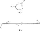
图7给出本发明缝合线组件的弯针部分的侧视图;Figure 7 provides a side view of the looper portion of the suture assembly of the present invention;
图8给出一个替换实施例的组织抓紧元件的截面图;Figure 8 presents a cross-sectional view of an alternate embodiment of a tissue grasping element;
图9给出图8的组织抓紧元件的正视图;Figure 9 presents a front view of the tissue grasping element of Figure 8;
图10给出本发明的又一个替换实施例,其提供双向缝合线;Figure 10 shows yet another alternative embodiment of the present invention, which provides a bi-directional suture;
图11给出本发明又一个替换实施例的透视图;Figure 11 provides a perspective view of yet another alternative embodiment of the present invention;
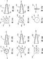
图12A和12B分别给出按照本发明构建的具有大致为圆锥形且有狭槽结构的组织抓紧元件的正视图和截面图;Figures 12A and 12B show front and cross-sectional views, respectively, of a tissue grasping element having a generally conical and slotted configuration constructed in accordance with the present invention;
图13A和13B分别给出一个限定大致为五边锥形的组织抓紧元件的正视图和截面图;Figures 13A and 13B respectively present a front view and a cross-sectional view of a tissue grasping element defining a generally pentagonal cone shape;
图14A和14B分别给出限定大致为正方形横截面的组织抓紧元件的正视图和截面图;14A and 14B present front and cross-sectional views, respectively, of a tissue grasping element defining a generally square cross-section;
图15A和15B分别给出限定四个凸出部(lobed)横截面的组织抓紧元件的正视图和截面图;Figures 15A and 15B present front and cross-sectional views, respectively, of a tissue grasping element defining four lobed cross-sections;
图16A和16B分别给出限定三个叶状横截面的组织抓紧元件的正视图和截面图;Figures 16A and 16B present front and cross-sectional views, respectively, of a tissue grasping element defining three lobed cross-sections;
图17A和17B分别给出平盘状组织抓紧元件的正视图和截面图;Figures 17A and 17B respectively provide a front view and a cross-sectional view of a flat disc-shaped tissue grasping element;
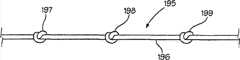
图18给出按照本发明构建并利用多个用于组织抓紧元件的打结的缝合线部分的侧视图;Figure 18 provides a side view of a plurality of knotted suture sections constructed and utilized for tissue grasping elements in accordance with the present invention;
图19给出按照本发明构建的支持一个多孔组织粘结套筒的完整缝合线组件的侧视图;Figure 19 provides a side view of a complete suture assembly supporting a porous tissue bonding sleeve constructed in accordance with the present invention;
图20给出具有被不均匀隔开的组织抓紧元件的缝合线部分的侧视图;Figure 20 presents a side view of a suture portion with unevenly spaced tissue grasping elements;
图21给出按照本发明构建并具有组织抓紧元件的缝合线部分的部分截面侧视图,其中组织抓紧元件通过利用激光焊接,超声焊接或粘接剂附着的连接而固定到缝合线组件的细长丝状体上;Figure 21 shows a partial cross-sectional side view of a suture portion constructed in accordance with the present invention and having a tissue grasping element secured to the elongated portion of the suture assembly by attachment using laser welding, ultrasonic welding, or adhesive attachment. on the filament;
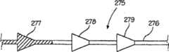
图22给出按照本发明构构建并具有多个通过模制或锻压工艺形成的组织抓紧元件的缝合线部分的部分截面侧视图;Figure 22 shows a partial cross-sectional side view of a suture portion constructed in accordance with the present invention and having a plurality of tissue grasping elements formed by a molding or swaging process;
图23给出按照本发明构建并具有多个组织啮合元件的缝合线部分的部分截面侧视图,其中组织啮合元件通过丝状体上的多个整体形成的膨大部分而定位;以及23 is a partial cross-sectional side view of a suture portion constructed in accordance with the present invention and having a plurality of tissue engaging elements positioned by a plurality of integrally formed enlarged portions on the filament; and
图24给出按照本发明构建的利用编织或纺织的多股丝状体的缝合线部分的侧视图。Figure 24 shows a side view of a portion of a suture constructed in accordance with the present invention utilizing braided or woven multi-strand filaments.
具体实施方式Detailed ways
图1给出按照本发明构建且总体标记为10的缝合线组件的侧视图。概括地,缝合线组件10包括四个基本元件,通常是直体11,柔性细长体20,多个组织啮合元件30~47,和弯曲体14。更具体地,缝合线组件10包括由塑料材料如聚丙烯等形成的细长直体11,并包括尖端12和连接器端13。缝合线组件10进一步包括一个柔性细长的丝状体20,其具有以下面描述的方式固定到连接器13的端部(末端)22。柔性体20进一步支持多个组织啮合元件30~47,这些啮合元件在下图4和5中更详细地说明。要充分注意,组织啮合元件30~47在结构上基本相同并接收在柔性体20上。此外,组织啮合元件30~47包括大致为圆锥形的结构,在缝合线组件与组织啮合中,该圆锥形结构向缝合线组件赋予方向(定向)特征或特性。如从图3中更清楚的看到那样,柔性体20进一步限定多个打结50~67,这些结打在柔性体20内以提供对组织啮合元件30~47相对柔性体20的移动的限制。柔性体20进一步限定一个被接收在弯曲体14的连接器16内的端部21。弯曲体14进一步限定(具有,define)锐利的尖端15。连接器13和16利用传统卷边连接(压接)固定柔性体20的端部22和21。本发明的缝合线可以由可吸收性或非吸收性材料制造以适于病人和手术。Figure 1 presents a side view of a suture assembly, generally designated 10, constructed in accordance with the present invention. In summary, suture assembly 10 includes four basic elements, a generally
如上所述,本发明的缝合线组件适用于各种伤口闭合,组织拉近,组织支持,悬挂和/或固定过程。然而,也如上所述,本发明缝合线组件特别良好地适用于整形手术过程中涉及面部提升或造型的过程。在这样的应用过程中,由组织啮合元件30~47提供的定向抓紧或定向特征进一步增强缝合线的提升和造型能力。在优选的制造中,整个缝合线由单丝材料,如聚丙烯等制成。可替换地,也可使用可吸收材料,如PDF。一旦插入到皮肤下面,组织啮合元件30~47的定向特征形成组织的永久支持结构并实际提升和造型该组织。虽然不限于在任何特定过程中应用,但本发明的缝合线良好地适用于提升和造型鼻唇线(nasolabral line)(微笑线(smile line)),以及收缩病人下颚或需要提升或造型的身体其他部分。与传统整形手术相比,利用本发明的过程(手术)极其安全并需要较少的时间。利用本发明缝合线的过程可在病人保持舒适清醒的局部麻醉的情形下执行。在该过程中,沿需要新造型的(路)线将缝合线深深插入到皮下组织中。通常,少至3个缝合线插入就显著提升面颊轮廓,同时少至2个正确安放的缝合线可用来回牵病人的下颚。该缝合线还可以用于抬高病人的额并拉回颈部组织。而且,本发明缝合线可在别处使用,如腰线拉平。一旦插入,在几个月后当组织啮合元件周围形成病人组织的胶原时,组织的抓紧力和提升效果会最大化。As noted above, the suture assemblies of the present invention are suitable for use in various wound closure, tissue approximation, tissue support, suspension and/or fixation procedures. However, as also noted above, the suture assembly of the present invention is particularly well suited for use in procedures involving face lifting or sculpting during plastic surgery procedures. During such application, the directional grasping or directional features provided by tissue engaging elements 30-47 further enhance the lifting and styling capabilities of the suture. In a preferred manufacture, the entire suture is made of a monofilament material, such as polypropylene or the like. Alternatively, absorbable materials such as PDF may also be used. Once inserted beneath the skin, the directional features of the tissue engaging elements 30-47 form a permanent support structure for the tissue and actually lift and shape the tissue. While not limited to application in any particular procedure, the sutures of the present invention are well suited for lifting and sculpting the nasolabral line (smile line), as well as retracting a patient's jaw or body in need of lifting or sculpting other parts. The procedure (surgery) utilizing the present invention is extremely safe and requires less time than conventional plastic surgery. Procedures utilizing the suture of the present invention can be performed under local anesthesia with the patient comfortably awake. In this procedure, sutures are inserted deep into the subcutaneous tissue along the lines requiring reshaping. Typically, as few as 3 suture insertions significantly lift the cheek contour, while as few as 2 properly placed sutures can be used to pull the patient's jaw back and forth. The suture can also be used to raise the patient's forehead and pull back the neck tissue. Moreover, the sutures of the present invention can be used elsewhere, such as waistline flattening. Once inserted, tissue gripping and lifting is maximized after several months as collagen of the patient's tissue forms around the tissue engaging elements.
对本领域技术人员来说很明显的是,在本发明缝合线组件中使用的组织啮合元件的数目一定程度上取决于选择,并可易于改变以便适于特定的应用或使用。因此,图1中所示的组织啮合元件的数目应视为本发明缝合线组件的操作原理的说明,而非对本发明结构的限制。It will be apparent to those skilled in the art that the number of tissue engaging elements employed in the suture assemblies of the present invention is somewhat a matter of choice and can be readily varied to suit a particular application or use. Accordingly, the number of tissue engaging elements shown in FIG. 1 should be considered as illustrative of the principles of operation of the suture assembly of the present invention, and not as a structural limitation of the present invention.
图2给出缝合线组件10的缝合线部分的侧视图。如上所述,本发明缝合线包括由诸如聚丙烯等的材料形成的细长柔性的优选单细丝体20。柔性体20限定端部21和端部22。多个组织啮合元件30~47串在柔性体20上。如从图3中更好看出的那样,柔性体10被打结以限定多个结(如图1中所示的结50~67)。结50~67以大致均匀的间隔设置在柔性体20上并用来限制组织啮合元件30~47在柔性体20上的移动。因此,很显然的是,组织啮合元件30~67连续地设置在柔性体20上,而且当组织啮合元件穿在柔性体20的端部22时,相应的多个结50到67打在每个组织啮合元件的前面。例如,组织啮合元件30~47在柔性体20上的组装是从组织啮合元件47穿过端部22到达主体20上所需位置开始的。然后,结67打在柔性体20上。然后,组织啮合元件67穿在柔性体20的端部22上,并靠近组织啮合元件47定位。然后,将柔性体22打结从而形成结66。该过程继续,随着每个组织啮合元件穿在柔性体20的端部22,且然后移动到前一组织啮合元件的附近,在该前一组织啮合元件后面,相应定位的结打在柔性体20上。一旦所有所需组织啮合元件装配到柔性体20上,且相应的限制移动的结已经打在柔性体20上,柔性体20易于组装到直体部分11和弯曲体部分14(参看图1)从而完成缝合线。FIG. 2 presents a side view of the suture portion of suture assembly 10 . As noted above, the suture of the present invention comprises an elongated, flexible, preferably
图3给出柔性体20的一部分的放大示图,其中示出按照上述方式固定的组织啮合元件44和45的截面。因此,在图3的例子中,所示的柔性体20支持组织啮合元件44和45。相应地,柔性体20已经打结从而形成一对结65和64,该每个结限制相应的组织啮合元件44和45的位置。以该方式,组织啮合元件44和45能够将牵引力从柔性体20传递到被元件44和45啮合的周围组织。再一次指出,该啮合是定向的,因为元件44和45在箭头48所示的方向上为组织提供显著更大的啮合力。Figure 3 gives an enlarged view of a portion of
图4给出组织啮合元件30的截面图。对本领域技术人员来说,显然组织啮合元件30~47(参看图1)构造上基本相同。因此,图4及结合其给出的说明应理解为可同样适用于组织啮合元件31~47。更具体地,组织啮合元件30大致是截头圆锥体形形状,并因此限定一个窄端75和一个张开端(宽端)77。端部75限定孔76,孔76被尺寸化以适于贴身装配在柔性体20上(参看图2)。张开端77为其内部部分提供增大的体积。组织啮合元件30的圆锥形形状和张开端77及内部78的开放特征一起合作而为元件30提供实质性的组织啮合特性。如上所述,本发明的组织啮合元件可根据需要用注模或冷锻技术制造。虽然大量合适的材料可用来制造本发明缝合线组件的组织啮合元件,但已经发现诸如聚丙烯等丁材料是合适并且是有利的。可替换地,也可使用可吸收材料。FIG. 4 presents a cross-sectional view of
图5给出组织啮合元件30的后视图,其示出张开端77和内部78。图5中还可看到孔76通过组织啮合元件的端部75的延伸。FIG. 5 presents a rear view of
图6给出直体11在没有附着至柔性体20的情况下的部分截面侧视图。如上所述,直体11是由合适材料,如聚丙烯等制造的,并限定形成一定程度的尖端结构的渐细端12和连接器端13。连接器端13以部分截面示出,并限定内部孔17。孔17被尺寸化以接收柔性体20的端部(参看图1)。一旦柔性体20的端部已经接收在孔17内,则连接器13通过利用传统的卷边工艺(压接)将直体11固定到柔性体20。FIG. 6 gives a partial cross-sectional side view of the
图7给出弯曲体14的部分截面图。如上所述,弯曲体14限定一个锐利尖端15和连接器端16。连接器端16限定内部孔18,该内孔18被尺寸化以贴配方式(snug-fit)接收柔性体20的端部(参看图1)。弯曲体14优选由塑料材料,如聚丙烯等形成。连接器端16连接到柔性体20从而形成上面图1所示的结构,该连接是通过柔性体20的插入端21(参看图1)向前拖动进入孔18,此后对连接器端16施加传统压接操作。端部15中形成的非常尖锐的点促进弯曲体14插入到皮肤或其他组织中。FIG. 7 shows a partial sectional view of the bending
图8和9分别给出示例性可替换实施例的组织啮合元件的截面图和后视图。图8和9中所示的组织啮合元件与图4和5中给出的组织啮合元件之间的差别是大致为椭圆形的横截面,而非上述实施例中的圆形横截面。Figures 8 and 9 present cross-sectional and rear views, respectively, of an exemplary alternative embodiment tissue engaging element. The difference between the tissue engaging elements shown in Figures 8 and 9 and those presented in Figures 4 and 5 is the generally oval cross-section rather than the circular cross-section of the above-described embodiments.
更具体地,图8给出椭圆形组织啮合元件的截面图,总体标记为70。组织啮合元件70限定其中形成有孔72的窄端71。元件70进一步限定张开端73和内部74。元件70优选是用注模或冷锻制造工艺制造的。对本领域技术人员来说,显然组织啮合元件70可为图1所示的组织啮合元件30~47提供直接的替换。进一步对本领域技术人员来说,显然多个组织啮合元件,如元件70可以与上述元件30~47相同的方式使用。在某些应用中发现组织啮合元件70的椭圆形横截面提供某些优势;然而,一般地,组织啮合元件70的操作与图4中所示的组织啮合元件30的操作基本相同。More specifically, FIG. 8 presents a cross-sectional view of an oval-shaped tissue engaging element, generally designated 70 .
图9给出组织啮合元件70的后视图,示出了其内形成的孔72和内部74。组织啮合元件70进一步限定张开端73。Figure 9 presents a rear view of
图10给出本发明缝合线定又一个可替换实施例的侧视图,其总体标记为80。通过比较图2中所示的本发明实施例和图10中所示的实施例,对本领域技术人员来说显然的是,缝合线80提供双向缝合。缝合线80包括具有端部82和83的细长柔性体81。第一组多个组织啮合元件90~99被支持在主体81上并通过多个结110~119定位。结110~119是以上述方式在细丝体81上打的简单结。缝合线80进一步包括第二组多个相反朝向的组织啮合元件100~109。组织啮合元件100~109以与元件90~99相反的取向设置在细丝体81上。以与上述缝合线相似的方式,多个结120~129打在丝体81上从而固定组织啮合元件100~109的位置。对本领域技术人员来说显然的是,组织啮合元件90~99与组织啮合元件100~109相反的取向为缝合线80提供了双向抓紧特征,其适用于要求双向抓紧的手术过程中的插入。通过查看图2和10,对本领域技术人员来说同样显然的是,可采用图2和10中所示组织啮合元件的设置的替换设置,而不背离本发明的精神和范畴。按照本发明缝合线的重要优点,组织啮合元件在丝状体上的固定和组织啮合元件的取向可按需要改变或组合从而满足给定过程中的特殊和具体要求。FIG. 10 shows a side view of yet another alternative embodiment of the suture set of the present invention, generally designated 80 . By comparing the embodiment of the present invention shown in FIG. 2 with the embodiment shown in FIG. 10, it will be apparent to those skilled in the art that suture 80 provides a bi-directional seam.
图11给出按照本发明的进一步可替换实施例构造的组织啮合元件的透视图。回顾上面图4和图5给出的本发明组织啮合元件的截头圆锥体实施例,图8和9给出形成组织啮合元件的可替换构造的椭圆形横截面锥体。图11示出本发明的多个有小平面的实施例,其中渐细组织啮合元件的外形限定多个小平面。因此在图11中,组织啮合元件85限定一个穿过其的孔87。组织啮合元件85大致为锥形从而限定一个窄端和一个宽端,并且其外表面被多个小平面86覆盖。组织啮合元件85适于替换到上述任意缝合线组件中,并且是本发明缝合线的组织啮合元件的进一步可替换形状的代表。因此,对本领域技术人员来说显然的是,可以考虑到并利用多种组织啮合元件结构或形状而不偏离本发明的精神和范畴。Figure 11 presents a perspective view of a tissue engaging element constructed in accordance with a further alternative embodiment of the present invention. Referring back to the frusto-conical embodiment of the tissue engaging element of the present invention given above in Figures 4 and 5, Figures 8 and 9 show an alternative configuration of an elliptical cross-sectional cone forming the tissue engaging element. Figure 11 illustrates a multi-faceted embodiment of the present invention wherein the profile of the tapered tissue engaging element defines a plurality of facets. Thus in FIG. 11,
同时参考图12A和12B,它们分别是正视图和截面图,组织抓紧元件140限定一个其内形成有前孔口(开口,aperture)145的截头圆锥体141。锥体141进一步限定多个细长的狭槽142、143和144。狭槽142、143和144进一步辅助组织啮合元件140的组织粘结或组织啮合。Referring concurrently to FIGS. 12A and 12B , which are front and cross-sectional views, respectively, the
同时参考图13A和13B,它们分别给出正视图和截面图,组织啮合元件150限定一个其内形成有孔口157的渐细体(锥形体)151。渐细体151进一步限定多个端面凸出部152、153、154、155和156。凸出部152~156配合而增强组织啮合元件150的组织粘结和组织啮合能力。Referring concurrently to Figures 13A and 13B, which are shown in front and cross-sectional views, respectively, the
同时参考图14A和14B,它们分别给出正视图和截面图,组织啮合元件160包括一个其内限定一个开口162的渐细体161。渐细体161限定一个大致为正方形的端部,该端部提供方形截面从而增强组织啮合元件160的组织抓紧和组织啮合能力。Referring concurrently to Figures 14A and 14B, which show front and cross-sectional views, respectively,
同时参考图15A和15B,它们分别给出正视图和截面图,组织啮合元件170限定一个其内形成有一个孔口(开口)172的渐细体171。渐细体171进一步限定在其较大端处的多个凸出部173、174、175和176。凸出部173~176增强组织啮合元件170的组织啮合和组织抓紧能力。Referring also to Figures 15A and 15B, which are shown in front and cross-sectional views, respectively, the
同时参考图16A和16B,它们分别给出正视图和截面图,组织啮合元件180包括一个其内限定有一个孔口182的渐细体181。渐细体181扩大端限定三个凸出部183、184和185。凸出部183~185增强组织啮合元件180的组织啮合和组织抓紧能力。Referring also to Figures 16A and 16B, which are shown in front and cross-sectional views, respectively,
同时参考图17A和17B,它们分别给出正视图和截面图,组织啮合元件190限定一个其内形成有中心孔口192的盘状体191。Referring concurrently to Figures 17A and 17B, which are shown in front and cross-sectional views, respectively, the
参考上面给出的不同形状的组织啮合元件,对本领域技术人员来说的是,可采用多种组织啮合元件形状而不偏离本发明的精神和范畴。从下面的讨论和附图中同样可显然看出的,相应的多种定位元件(positioning element)可用来与本文所述的不同组织啮合元件配合。组织啮合元件的基本功能是为缝合线提供抓紧和啮合特征,而定位元件,如上述打结的功能是限制组织啮合元件的移动,并由此在组织和组织啮合元件间传递对缝合体的抓紧力。With reference to the different shapes of tissue engaging elements given above, it will be apparent to those skilled in the art that a variety of tissue engaging element shapes may be employed without departing from the spirit and scope of the invention. As will also be apparent from the discussion below and from the drawings, a corresponding variety of positioning elements can be used to cooperate with the different tissue engaging elements described herein. The primary function of the tissue-engaging element is to provide grip and engagement features to the suture, while the function of the positioning element, such as the aforementioned knot, is to limit the movement of the tissue-engaging element and thereby impart grip to the suture between the tissue and the tissue-engaging element force.
图18给出缝合线部分,其包括在缝合线细长柔性体上打结形成的组织抓紧元件。对本领域技术人员来说显然的是,图18示出按照本发明构建的缝合线的一部分。参考图1,可以记得,完整的缝合线结构包括一个柔性细长体以及细长的直针或弯针部分。因此可以理解,图18中所示的实施例形成采用上述结构剩余部分的本发明缝合线的一部分。更具体地,图18示出具有细长柔性体196的缝合线195的一部分,该细长柔性体196支持多个组织啮合元件197、198和199,这些组织啮合元件197、198和199是通过在细长柔性体196上打结形成的。对本领域技术人员来说显然的是,在细长柔性体196上打上例如结197、198和199的结的目的是提供用作组织啮合元件的扩大区段。因此,各种不同地结可打在柔性体196上从而提供该功能,而不会偏离本发明的精神和范畴。Figure 18 shows a portion of a suture comprising a tissue grasping element formed by knotting the elongated flexible body of the suture. It will be apparent to those skilled in the art that Figure 18 shows a portion of a suture constructed in accordance with the present invention. Referring to Figure 1, it will be recalled that the complete suture structure comprises a flexible elongated body and elongated straight or curved needle portions. It will therefore be appreciated that the embodiment shown in Figure 18 forms part of a suture of the present invention employing the remainder of the structure described above. More specifically, FIG. 18 shows a portion of a
图19给出按照本发明的可替换实施例构造的完整缝合线结构的侧视图,其总体标记为200。概括地,缝合线组件200大致是按照图1中给出的缝合线10的制造进行构建的,因为其提供一对大致为刚性的并通过细长柔性体连接的针状结构。应该指出,进一步的相似性是缝合线组件200包括多个组织啮合元件,这些组织啮合元件通过定位元件,如结或放大珠状体而设置在细长柔性体上。缝合线组件200与上面给出的缝合线组件不同,因为其进一步包括柔性体的细长部,该细长部没有组织啮合元件,且其支持位于柔性体上的细长组织粘结套筒。如下面所述,组织粘结套筒的功能是提供进一步增强缝合线200的抓紧和组织啮合特征的结构。本质上,组织粘结套筒的多孔结构允许组织生长到孔中,并强有力地粘结套筒且最终缝合到病人组织上。本发明缝合线可用多种可植入材料制造,包括吸收性或非吸收性材料。Figure 19 presents a side view of a complete suture structure, generally designated 200, constructed in accordance with an alternative embodiment of the present invention. In summary,
更具体地,缝合线200包括一对细长的大致为弹性的分别有尖端202和205的针201和204。针201和204进一步限定各自连接端203和206。细长柔性体210固定在针201和204的连接端203和206之间。注意,在图19中所示的缝合线200的实例中,针201和204都限定直针。然而,对本领域技术人员来说显然的是,针201和204任一个都可限定如上面图1所示的弯曲或带钩区段。More specifically,
按照上述制造,细长柔性体210支持多个隔开的组织啮合元件201~220,这些组织啮合元件201~220通过相应的多个结221~230定位在柔性体210上。而且,细长柔性体210支持第二组多个组织啮合元件231~240,这些组织啮合元件231~240通过相应的多个结241~250或其他定位元件241~250定位在柔性体210上。根据下面的说明,本领域技术人员可显然看出,定位元件221~230以及定位元件241~250可替换地是细长柔性体210上的结或可包括下面说明并在图20中示出的带头或带珠状体的区段。As constructed above, elongate
按照本发明的该替换实施例,细长柔性体210限定了一个没有组织啮合元件211~220和231~240的部分。细长的柔性组织粘结套筒251就支持在细长柔性体210的该部分上。用于说明的目的,所示的套筒251被支持在细长柔性体210上并与两组组织啮合元件大致等距离。然而,显然的是,套筒251的位置可按照具体的缝合线200的要求而改变。套筒251是通过套筒251的各端252和253处的定位元件254和255定位的。According to this alternative embodiment of the present invention, elongated
在优选的制造中,套筒251是细长的并有一定弹性,而且限定一个允许其被支持在细长柔性体210上的中心通道。在进一步按照本发明的优选制造中,套筒251优选由材料,如高太克斯(gortex)或其他合适可植入材料形成。随着套筒251的大致多孔结构允许病人体内组织“生长到”套筒251体内或与其粘结,套筒251的优选功能得以实现。随着病人组织延伸到套筒251体内并与其粘结,该过程提供增强的组织抓紧能力。In a preferred manufacture, the
如上所述,本发明的缝合线可用多种不同形状的组织啮合元件制造。此外,也如上面提到的那样,这些组织啮合元件的连接或定位可类似地在缝合线的细长柔性体部分上改变。因此,下面给出的图20~24提供这些可替换实施例的缝合线部分的侧视图,这些缝合线可按照本发明的不同实施例制造。因此,在图20~24中,可以理解这些图示出了缝合线组件的一部分,该缝合线组件整体是以图1和19的方式并按照这里所示的缝合线10和200的构造制造的。As noted above, the sutures of the present invention can be manufactured with a variety of differently shaped tissue engaging elements. Furthermore, also as noted above, the attachment or positioning of these tissue engaging elements may similarly be varied over the elongate flexible body portion of the suture. Accordingly, Figures 20-24 presented below provide side views of portions of these alternative embodiments of sutures that may be manufactured in accordance with various embodiments of the present invention. Accordingly, in FIGS. 20-24, it will be appreciated that these figures illustrate a portion of a suture assembly which as a whole is manufactured in the manner of FIGS. 1 and 19 and according to the configuration of
更具体地,参考图20,所示缝合线部分260具有细长的柔性体261,其上形成有多个定位元件262、263和264。定位元件262、263和264可替换地包括打在柔性体261上的结,或可以图3所示的方式模制或锻造在该柔性体上。在一个简单实施例中,组织啮合元件可通过简单“压平”该柔性体以在一维方向上形成放大部分而形成。柔性体261支持相应的多个组织啮合元件265、266和267。图20中值得指出的是,组织啮合元件265、266和267是不均匀间隔的。因此,对本领域技术人员来说显然的是,虽然在许多情形中,可考虑并利用均匀的组织啮合元件间隔,但在其他应用中,组织啮合元件的间隔可改变并按需要可以是不均匀的。More particularly, referring to FIG. 20, a
图21给出的缝合线部分270具有细长的柔性体271,组织啮合元件272被支持在该柔性体上。图21中值得指出的是,采用组织啮合元件272和柔性体271之间的连接273,该连接提供直接连接并可消除对定位元件的需求。例如,该连接可包括超声焊接、激光焊接、粘合剂连接或其他的直接连接机理。Figure 21 shows
图22给出缝合线部分275的部分截面图。缝合线部分275的重要性是,其利用一体结构的柔性体和组织啮合元件。因此,柔性体276被模制或锻造从而提供多个组织啮合元件277、278和279。这样的模制或锻造工艺是本领域已知的并可用在本发明的某些实施例中。FIG. 22 presents a partial cross-sectional view of
图23给出缝合线280的局部截面图,缝合线280具有细长的柔性体281,其上形成多个定位元件282、283和284作为柔性体281的一体部分。该一体成形可由锻造或模制工艺或钉压(staking)或冲压(impacting)工艺提供。对于如图所示的定位元件282、283和284,相应的多个组织啮合元件285、286和287位于柔性体281上。Figure 23 shows a partial cross-sectional view of a
图24给出缝合线部分的侧视图,其总体标记为290,该缝合线部分采用多股编织的或纺织的细长柔性体291。柔性体291可由多种可植入材料,如编织的聚酯、尼龙或其他材料制造。多个定位元件292和293在柔性体291上形成,如其上打的结。相应的多个组织啮合元件294和295也在柔性体291上示出。对于图24中所示的本发明实施例,重要的是,柔性体291的编织或纺织特征进一步增强整个缝合线结构的组织粘结特征。柔性体291的编织或纺织的特征允许组织生长从而粘附到并生长到多个编织的或纺织的柔性体291各个股丝间的间隙中。以该方式,组织粘附性被大大增强,因为缝合线组件的整个柔性体提供直接的组织粘结,这比在缝合线中使用的单丝柔性体实现的效果好。柔性体291的编织或纺织的特征在最初就提供更好的连接或组织粘结。但可能更重要的是,最终生长到编织的或纺织的股丝内的间隙内,这提供沿缝合线的柔性体部分的整个长度的组织啮合。FIG. 24 presents a side view of a suture portion, generally designated 290 , employing a multi-strand braided or woven elongated
本文所展示的是一种新颖的缝合线组件,其提供一种可植入的定向凸轮式装置,该凸轮式装置可制造成定向或双向的。所示缝合线组件可用注模或冷锻制造技术制造并适用于伤口闭合、组织挤压、组织支持、悬挂和/或固定。所示组织啮合元件具有圆形横截面或椭圆形横截面。本发明缝合线组件可用导引器或不用导引器插入到人体中。本发明缝合线被设计成与手术后愈合过程结合工作。所示的本发明缝合线组件保持伤口闭合而无需缝合线打结从而维持组织拉近。Presented herein is a novel suture assembly that provides an implantable directional cam-like device that can be manufactured to be directional or bi-directional. The suture assembly shown can be manufactured using injection molding or cold forging manufacturing techniques and is suitable for wound closure, tissue compression, tissue support, suspension and/or fixation. The tissue engaging elements shown have circular cross-sections or oval cross-sections. The suture assembly of the present invention can be inserted into the body with or without an introducer. The sutures of the present invention are designed to work in conjunction with the post-surgical healing process. The illustrated suture assembly of the present invention holds the wound closed without suture knotting to maintain tissue approximation.
虽然示出并说明了本发明的特定实施例,但对本领域技术人员来说显然的是,可不偏离本发明而在更宽泛的方面做出变化和修改。因此,所附权利要求的目的是涵盖所有落入本发明真正的精神和范畴内的变化和修改。While particular embodiments of the present invention have been shown and described, it will be obvious to those skilled in the art that changes and modifications may be made without departing from the invention in its broader aspects. Therefore, it is the intention in the appended claims to cover all such changes and modifications as fall within the true spirit and scope of the invention.
Claims (6)
Translated fromChineseApplications Claiming Priority (3)
| Application Number | Priority Date | Filing Date | Title |
|---|---|---|---|
| US11/500,733 | 2006-08-07 | ||
| US11/500,733US7582105B2 (en) | 2004-06-30 | 2006-08-07 | Suture for wound closure, tissue approximation, tissue support, suspension and/or fixation |
| PCT/US2007/015876WO2008020937A2 (en) | 2006-08-07 | 2007-07-12 | Suture for wound closure, tissue approximation, tissue support, suspension and/ or fixation |
Related Child Applications (1)
| Application Number | Title | Priority Date | Filing Date |
|---|---|---|---|
| CN2013101904070ADivisionCN103251433A (en) | 2006-08-07 | 2007-07-12 | Suture for wound closure, tissue approximation, tissue support, suspension and/ or fixation |
Publications (2)
| Publication Number | Publication Date |
|---|---|
| CN101500495A CN101500495A (en) | 2009-08-05 |
| CN101500495Btrue CN101500495B (en) | 2013-05-01 |
Family
ID=39082508
Family Applications (2)
| Application Number | Title | Priority Date | Filing Date |
|---|---|---|---|
| CN2007800293496AActiveCN101500495B (en) | 2006-08-07 | 2007-07-12 | Suture for wound closure, tissue approximation, tissue support, suspension and/or fixation |
| CN2013101904070APendingCN103251433A (en) | 2006-08-07 | 2007-07-12 | Suture for wound closure, tissue approximation, tissue support, suspension and/ or fixation |
Family Applications After (1)
| Application Number | Title | Priority Date | Filing Date |
|---|---|---|---|
| CN2013101904070APendingCN103251433A (en) | 2006-08-07 | 2007-07-12 | Suture for wound closure, tissue approximation, tissue support, suspension and/ or fixation |
Country Status (13)
| Country | Link |
|---|---|
| US (2) | US7582105B2 (en) |
| EP (1) | EP2051747B1 (en) |
| JP (5) | JP5506383B2 (en) |
| KR (1) | KR101241955B1 (en) |
| CN (2) | CN101500495B (en) |
| AU (1) | AU2007284933B2 (en) |
| BR (1) | BRPI0716640B1 (en) |
| CA (1) | CA2695924C (en) |
| MX (1) | MX2009001437A (en) |
| MY (1) | MY148454A (en) |
| NZ (1) | NZ574434A (en) |
| RU (1) | RU2438602C2 (en) |
| WO (1) | WO2008020937A2 (en) |
Cited By (1)
| Publication number | Priority date | Publication date | Assignee | Title |
|---|---|---|---|---|
| CN103251433A (en)* | 2006-08-07 | 2013-08-21 | 西露艾特利福特有限公司 | Suture for wound closure, tissue approximation, tissue support, suspension and/ or fixation |
Families Citing this family (141)
| Publication number | Priority date | Publication date | Assignee | Title |
|---|---|---|---|---|
| US8795332B2 (en) | 2002-09-30 | 2014-08-05 | Ethicon, Inc. | Barbed sutures |
| US6241747B1 (en)* | 1993-05-03 | 2001-06-05 | Quill Medical, Inc. | Barbed Bodily tissue connector |
| US5931855A (en) | 1997-05-21 | 1999-08-03 | Frank Hoffman | Surgical methods using one-way suture |
| US7056331B2 (en)* | 2001-06-29 | 2006-06-06 | Quill Medical, Inc. | Suture method |
| US6848152B2 (en) | 2001-08-31 | 2005-02-01 | Quill Medical, Inc. | Method of forming barbs on a suture and apparatus for performing same |
| US6773450B2 (en) | 2002-08-09 | 2004-08-10 | Quill Medical, Inc. | Suture anchor and method |
| US8100940B2 (en) | 2002-09-30 | 2012-01-24 | Quill Medical, Inc. | Barb configurations for barbed sutures |
| US20040088003A1 (en) | 2002-09-30 | 2004-05-06 | Leung Jeffrey C. | Barbed suture in combination with surgical needle |
| US7232446B1 (en)* | 2003-01-16 | 2007-06-19 | Farris Alex F | Pneumatic suture instrument |
| US7624487B2 (en) | 2003-05-13 | 2009-12-01 | Quill Medical, Inc. | Apparatus and method for forming barbs on a suture |
| US10548592B2 (en) | 2004-05-14 | 2020-02-04 | Ethicon, Inc. | Suture methods and devices |
| US8663277B2 (en)* | 2005-06-29 | 2014-03-04 | Ethicon, Inc. | Braided barbed suture |
| US8728096B2 (en)* | 2006-10-24 | 2014-05-20 | Boston Scientific Scimed, Inc. | Ligating band dispenser with a sliding deployment system |
| FR2914178B1 (en)* | 2007-03-27 | 2010-05-14 | Cie De Rech En Composants Impl | IMPLANTABLE REINFORCEMENT PROSTHESIS WITH MOUNTING MEANS |
| US8915943B2 (en) | 2007-04-13 | 2014-12-23 | Ethicon, Inc. | Self-retaining systems for surgical procedures |
| US20080281357A1 (en)* | 2007-05-09 | 2008-11-13 | An-Min Jason Sung | Looped tissue-grasping device |
| US20090082806A1 (en)* | 2007-09-24 | 2009-03-26 | Hs West Investments, Llc | Meniscal repair system |
| ES2398779T3 (en) | 2007-09-27 | 2013-03-21 | Ethicon Llc | Self-retaining sutures that include tissue retention elements with enhanced strength |
| US20090099597A1 (en)* | 2007-10-12 | 2009-04-16 | Isse Nicanor G | Suture assembly with tissue engaging elements |
| US20090112259A1 (en)* | 2007-10-31 | 2009-04-30 | Angiotech Pharmaceuticals, Inc. | Recombinant expressed bioadsorbable polyhydroxyalkonate monofilament and multi-filaments self-retaining sutures |
| US20090143819A1 (en)* | 2007-10-31 | 2009-06-04 | D Agostino William L | Coatings for modifying monofilament and multi-filaments self-retaining sutures |
| WO2009086172A2 (en) | 2007-12-19 | 2009-07-09 | Angiotech Pharmaceuticals, Inc. | Self-retaining sutures with heat-contact mediated retainers |
| US8916077B1 (en) | 2007-12-19 | 2014-12-23 | Ethicon, Inc. | Self-retaining sutures with retainers formed from molten material |
| US8118834B1 (en) | 2007-12-20 | 2012-02-21 | Angiotech Pharmaceuticals, Inc. | Composite self-retaining sutures and method |
| US8615856B1 (en) | 2008-01-30 | 2013-12-31 | Ethicon, Inc. | Apparatus and method for forming self-retaining sutures |
| US8875607B2 (en) | 2008-01-30 | 2014-11-04 | Ethicon, Inc. | Apparatus and method for forming self-retaining sutures |
| US8920462B2 (en) | 2008-02-15 | 2014-12-30 | Rex Medical, L.P. | Vascular hole closure device |
| US8491629B2 (en) | 2008-02-15 | 2013-07-23 | Rex Medical | Vascular hole closure delivery device |
| US20110029013A1 (en) | 2008-02-15 | 2011-02-03 | Mcguckin James F | Vascular Hole Closure Device |
| US8070772B2 (en) | 2008-02-15 | 2011-12-06 | Rex Medical, L.P. | Vascular hole closure device |
| US8920463B2 (en) | 2008-02-15 | 2014-12-30 | Rex Medical, L.P. | Vascular hole closure device |
| US9226738B2 (en) | 2008-02-15 | 2016-01-05 | Rex Medical, L.P. | Vascular hole closure delivery device |
| ES2706295T3 (en) | 2008-02-21 | 2019-03-28 | Ethicon Llc | Method and apparatus for raising retainers in self-retaining sutures |
| US8216273B1 (en) | 2008-02-25 | 2012-07-10 | Ethicon, Inc. | Self-retainers with supporting structures on a suture |
| US8641732B1 (en) | 2008-02-26 | 2014-02-04 | Ethicon, Inc. | Self-retaining suture with variable dimension filament and method |
| WO2009111802A1 (en)* | 2008-03-07 | 2009-09-11 | Alure Medical, Inc. | Minimally invasive tissue support |
| US20090259251A1 (en)* | 2008-04-11 | 2009-10-15 | Cohen Matthew D | Loop suture |
| SG188784A1 (en) | 2008-04-15 | 2013-04-30 | Ethicon Llc | Self-retaining sutures with bi-directional retainers or uni-directional retainers |
| US9011489B2 (en)* | 2008-05-14 | 2015-04-21 | Boston Scientific Scimed, Inc. | Surgical composite barbed suture |
| US8961560B2 (en) | 2008-05-16 | 2015-02-24 | Ethicon, Inc. | Bidirectional self-retaining sutures with laser-marked and/or non-laser marked indicia and methods |
| US7967841B2 (en)* | 2008-06-02 | 2011-06-28 | Ethicon, Inc. | Methods for using looped tissue-grasping devices |
| US8821539B2 (en)* | 2008-07-23 | 2014-09-02 | Ethicon, Inc. | Collapsible barbed sutures having reduced drag and methods therefor |
| EP2352435B1 (en) | 2008-10-31 | 2019-11-27 | Sinclair Pharmaceuticals Limited | Minimally invasive tissue support system with a superior tissue support and an inferior anchor |
| EP2352440B1 (en) | 2008-11-03 | 2019-02-20 | Ethicon LLC | Length of self-retaining suture and device for using the same |
| US8449573B2 (en) | 2008-12-05 | 2013-05-28 | Boston Scientific Scimed, Inc. | Insertion device and method for delivery of a mesh carrier |
| US9204965B2 (en) | 2009-01-14 | 2015-12-08 | Lc Therapeutics, Inc. | Synthetic chord |
| US8968334B2 (en)* | 2009-04-17 | 2015-03-03 | Boston Scientific Scimed, Inc. | Apparatus for delivering and anchoring implantable medical devices |
| EP2263608B1 (en)* | 2009-06-19 | 2016-09-07 | Arthrex, Inc. | Bone-tendon-bone suture button construct |
| US9011487B2 (en)* | 2009-08-27 | 2015-04-21 | Ethicon, Inc. | Barbed sutures having pledget stoppers and methods therefor |
| US8210085B2 (en) | 2009-08-27 | 2012-07-03 | Ethicon, Inc. | Automated systems and methods for making braided barbed sutures |
| US20110213386A1 (en)* | 2009-10-01 | 2011-09-01 | Edwin Ryan | Ophthalmic wound closure devices and methods |
| US9468435B2 (en)* | 2009-12-23 | 2016-10-18 | Cook Medical Technologies Llc | Wound closure device |
| WO2011091483A1 (en)* | 2010-01-26 | 2011-08-04 | Dokter Philippe Ehlinger, Besloten Vennootschap Met Beperkte Aansprakelijheid | Surgical thread and surgical device for lifting and suspension of soft tissues. |
| NZ626274A (en) | 2010-05-04 | 2015-03-27 | Ethicon Llc | Laser cutting system and methods for creating self-retaining sutures |
| EP3155978B1 (en) | 2010-06-11 | 2022-04-13 | Cilag GmbH International | Suture delivery tools for endoscopic and robot-assisted surgery |
| US11007296B2 (en) | 2010-11-03 | 2021-05-18 | Ethicon, Inc. | Drug-eluting self-retaining sutures and methods relating thereto |
| JP6013352B2 (en) | 2010-11-09 | 2016-10-25 | エシコン・エルエルシーEthicon LLC | Emergency indwelling suture and package |
| US8814905B2 (en) | 2010-11-23 | 2014-08-26 | Depuy Mitek, Llc | Surgical filament snare assemblies |
| US9345468B2 (en) | 2010-11-23 | 2016-05-24 | Medos International Sárl | Surgical filament snare assemblies |
| US8821543B2 (en) | 2010-12-23 | 2014-09-02 | Depuy Mitek, Llc | Adjustable anchor systems and methods |
| CN102551820A (en)* | 2010-12-16 | 2012-07-11 | 陕西福泰医疗科技有限公司 | Titanium nickel memory alloy cosmetic suture thread |
| ES2701781T3 (en)* | 2010-12-23 | 2019-02-25 | Surgimatix Inc | Cutaneous suture device that uses rotating needles |
| WO2012088496A2 (en) | 2010-12-23 | 2012-06-28 | Depuy Mitek, Inc. | Adjustable anchor systems and methods |
| KR101132841B1 (en)* | 2011-03-07 | 2012-04-02 | 김영재 | A suture |
| CN103889340B (en) | 2011-03-23 | 2018-09-28 | 伊西康有限责任公司 | Self-retaining variable loop suture |
| KR101057377B1 (en) | 2011-03-24 | 2011-08-17 | 한스바이오메드 주식회사 | Medical suture having a fine protrusion on the surface and a manufacturing method thereof |
| US20130172931A1 (en) | 2011-06-06 | 2013-07-04 | Jeffrey M. Gross | Methods and devices for soft palate tissue elevation procedures |
| KR101155817B1 (en)* | 2011-10-31 | 2012-06-12 | 김종우 | Implant for tissue lifting |
| CN116746973A (en) | 2011-11-14 | 2023-09-15 | 亚瑟罗凯尔公司 | Tissue repair assembly |
| US10456267B2 (en)* | 2011-11-23 | 2019-10-29 | Medos International Sarl | Lateral cage stabilization |
| KR101185583B1 (en)* | 2011-12-27 | 2012-09-24 | 김영재 | A suture which need not be knotted and a kit comprising the suture |
| US9107660B2 (en) | 2012-02-01 | 2015-08-18 | Covidien Lp | Wound closure device |
| US9220492B2 (en)* | 2012-02-01 | 2015-12-29 | Covidien Lp | Wound closure device |
| ES2655821T3 (en) | 2012-02-23 | 2018-02-21 | Northwestern University | Enhanced Suture |
| US8790370B2 (en) | 2012-03-30 | 2014-07-29 | Depuy Mitek, Llc | Surgical filament assemblies |
| KR101326366B1 (en)* | 2012-04-23 | 2013-11-11 | 정홍우 | A stitching fiber for plastic surgery |
| US9345567B2 (en) | 2012-05-07 | 2016-05-24 | Medos International Sàrl | Systems, devices, and methods for securing tissue using snare assemblies and soft anchors |
| US9060763B2 (en) | 2012-05-07 | 2015-06-23 | Medos International Sàrl | Systems, devices, and methods for securing tissue |
| US9060764B2 (en) | 2012-05-07 | 2015-06-23 | Medos International Sàrl | Systems, devices, and methods for securing tissue |
| US8894684B2 (en) | 2012-05-07 | 2014-11-25 | Medos International Sàrl | Systems, devices, and methods for securing tissue using a suture having one or more protrusions |
| KR101379546B1 (en)* | 2012-06-05 | 2014-03-28 | 정찬희 | Embedding therapy needle |
| AU2013206414B2 (en)* | 2012-06-22 | 2018-11-01 | Peter Michael Sutherland Walker | Improved Graft Fixation Device |
| KR101396642B1 (en) | 2012-09-03 | 2014-05-16 | 이준길 | A stitching fiber for plastic surgery |
| US9763655B2 (en) | 2012-09-20 | 2017-09-19 | Medos International Sarl | Systems, devices, and methods for securing tissue using hard anchors |
| US9486201B2 (en)* | 2012-09-27 | 2016-11-08 | Depuy Mitek, Llc | Directionally specific bone anchors and method |
| US9427228B2 (en)* | 2012-11-09 | 2016-08-30 | Karl Storz Gmbh & Co. Kg | Suture cartridge for meniscal repair |
| US10178990B2 (en) | 2012-12-05 | 2019-01-15 | Y. Jacobs Medical Inc. | Apparatus for inserting surgical thread, and surgical procedure kit for inserting surgical thread comprising same |
| US10010317B2 (en)* | 2012-12-05 | 2018-07-03 | Young Jae Kim | Method of improving elasticity of tissue of living body |
| US9271716B2 (en) | 2012-12-27 | 2016-03-01 | Medos International Sàrl | Surgical constructs and methods for securing tissue |
| US9872679B2 (en)* | 2013-02-05 | 2018-01-23 | Ethicon, Inc. | Locally reversible barbed sutures |
| US10182806B2 (en) | 2013-03-12 | 2019-01-22 | Arthrocare Corporation | Tissue repair assembly |
| US9737293B2 (en) | 2013-03-15 | 2017-08-22 | Medos International Sàrl | Surgical constructs with collapsing suture loop and methods for securing tissue |
| KR101490613B1 (en)* | 2013-08-06 | 2015-02-11 | 박용호 | Plastic and cosmetic surgical device for physical lifting |
| US9474338B2 (en) | 2013-10-11 | 2016-10-25 | Aplix | Fastener |
| US10188179B2 (en) | 2013-10-11 | 2019-01-29 | Aplix | Fastener |
| WO2015083864A1 (en)* | 2013-12-06 | 2015-06-11 | 주식회사 와이제이콥스메디칼 | Apparatus for inserting medical tube and surgical procedure kit for inserting medical tube, having same |
| US9962150B2 (en) | 2013-12-20 | 2018-05-08 | Arthrocare Corporation | Knotless all suture tissue repair |
| GB2506549B (en)* | 2013-12-26 | 2014-08-13 | Falah Hasan Ali | Reinforcing mean for Silhouette face lift sutures |
| JP5789690B1 (en)* | 2014-03-26 | 2015-10-07 | 医療法人社団翔友会 | Thread and detainment member |
| US9561026B2 (en) | 2014-08-19 | 2017-02-07 | Depuy Mitek, Llc | Segmented suture anchor |
| GB2535799B (en)* | 2015-02-27 | 2017-02-15 | Sinclair Pharmaceuticals Ltd | Device |
| WO2016154609A1 (en)* | 2015-03-26 | 2016-09-29 | Central Park Diagnostics, Inc. | Suture delivery device, and suture, for facilitating fibrosis and healing |
| EP3085820B1 (en) | 2015-04-22 | 2017-12-20 | Sofradim Production | A method for forming a barbed suture and the barbed suture thus obtained |
| EP3085332B1 (en) | 2015-04-23 | 2019-02-27 | Sofradim Production | Package for a surgical mesh |
| RU2607156C1 (en)* | 2015-11-06 | 2017-01-10 | Вадим Викторович Евдокимов | Surgical thread for closing and/or fixation of tissues (versions) |
| KR101701434B1 (en)* | 2015-11-18 | 2017-02-13 | 정영춘 | New facial and body lifting sutures |
| JP2020189103A (en)* | 2016-01-28 | 2020-11-26 | ジェテマ カンパニー リミテッド | New sutural thread for face and body lifting |
| TWI602535B (en)* | 2016-02-05 | 2017-10-21 | Beauty-Com Biotechnology Co Ltd | Surgical suture group |
| US11058538B2 (en) | 2016-03-10 | 2021-07-13 | Charles Somers Living Trust | Synthetic chord for cardiac valve repair applications |
| EP3225175A1 (en)* | 2016-04-01 | 2017-10-04 | Beauty-Com Biotechnology Co., Ltd | Surgical suture |
| GB2551202A (en) | 2016-06-10 | 2017-12-13 | Univ Cape Town | Implantable device |
| KR101897793B1 (en)* | 2016-07-08 | 2018-09-12 | 김근식 | Suture for lifting and a method of manufacturing the same |
| CN109561954A (en)* | 2016-07-08 | 2019-04-02 | (株)东方医疗 | Lifting suture and its manufacturing method |
| KR101969910B1 (en)* | 2017-06-05 | 2019-04-17 | 주식회사 동방메디컬 | Suture for lifting and a method of manufacturing the same |
| GB2540293B (en)* | 2016-10-02 | 2018-02-14 | Hasan Ali Falah | Beads enriched silhouette soft (TM) face lift suture |
| US10524776B2 (en)* | 2016-11-08 | 2020-01-07 | Arthrex, Inc. | Soft suture anchor assembly with barbed suture and attached tissue fixation disk |
| KR20190031859A (en)* | 2017-09-18 | 2019-03-27 | 21세기메디칼 주식회사 | Biodegradable Suture having Retainers and the method thereof |
| RU2669045C1 (en)* | 2017-09-27 | 2018-10-05 | Надежда Александровна Соловых | Surgical suture material and method of performing cosmetic surgery |
| AU2018272115B2 (en) | 2018-05-16 | 2024-03-21 | George Swope MUNDAY | Apparatus and method for closing a surgical site |
| KR102184634B1 (en)* | 2018-05-18 | 2020-11-30 | (주)제이월드 | Suture kit |
| US11272924B2 (en) | 2018-07-18 | 2022-03-15 | Arthrex, Inc. | Knotless closure sutures and methods of tissue fixation |
| KR102094519B1 (en)* | 2018-09-05 | 2020-04-23 | 김근식 | Suture for lifting and a method of manufacturing the same |
| US11504105B2 (en) | 2019-01-25 | 2022-11-22 | Rex Medical L.P. | Vascular hole closure device |
| KR102042717B1 (en)* | 2019-01-31 | 2019-11-08 | 복정희 | Lifting Method and Needle |
| CN109864835B (en)* | 2019-04-15 | 2024-06-11 | 童妍(上海)医疗器械有限公司 | Suture line, suture device and application of suture line |
| CN109864834A (en)* | 2019-04-15 | 2019-06-11 | 易浦润(上海)生物技术有限公司 | A kind of suture, stitching devices and its application |
| CN110123485B (en)* | 2019-06-19 | 2024-05-28 | 童妍(上海)医疗器械有限公司 | Unidirectional lifting implantation line, lifting device and shaping method using unidirectional lifting implantation line |
| US11224419B2 (en)* | 2019-06-28 | 2022-01-18 | Cilag Gmbh International | Bi-directional barbed suture with tailored suture segments |
| US11439383B2 (en)* | 2019-08-20 | 2022-09-13 | Abbott Cardiovascular Systems, Inc. | Self locking suture and self locking suture mediated closure device |
| CA3153882A1 (en)* | 2019-10-31 | 2021-05-06 | Ho Sung Lee | Medical suture and method for producing same |
| AU2021220864B2 (en) | 2020-02-11 | 2024-03-07 | Embody, Inc. | Surgical anchoring device, deployment device, and method of use |
| US12138355B2 (en)* | 2020-12-10 | 2024-11-12 | Covidien Lp | Suture with tension indicator |
| CN112674906B (en)* | 2020-12-24 | 2024-07-09 | 童妍(上海)医疗器械有限公司 | Pulling wire and preparation method thereof |
| CN112831871B (en)* | 2021-01-08 | 2021-12-21 | 杭州恒岳新材料有限公司 | Terylene blended yarn and production process thereof |
| US11826041B2 (en)* | 2021-02-12 | 2023-11-28 | Washington University | Barbed rod for linear tissue closure and approximation |
| US11701104B2 (en) | 2021-06-08 | 2023-07-18 | George Swope MUNDAY | Apparatus for closing a surgical site |
| US20220387023A1 (en) | 2021-06-08 | 2022-12-08 | George Swope MUNDAY | Apparatus for closing a surgical site |
| CN114305555A (en)* | 2022-01-25 | 2022-04-12 | 深圳市创科医疗科技有限公司 | Tissue defect closure device and surgical suture |
| KR20230125363A (en)* | 2022-02-21 | 2023-08-29 | 메디퓨처스 주식회사 | Method for manufacturing double-layer medical thread with improved tensile strength |
| KR102698031B1 (en)* | 2023-08-24 | 2024-08-22 | 임기표 | Surgical suture for lifting |
| KR102688539B1 (en) | 2023-12-28 | 2024-08-05 | 비티에스메디컬 주식회사 | Thread for lifting |
Citations (1)
| Publication number | Priority date | Publication date | Assignee | Title |
|---|---|---|---|---|
| US20060079935A1 (en)* | 2004-06-30 | 2006-04-13 | Alwin Kolster | Suture for wound closure, tissue approximation, tissue support, suspension and/or fixation |
Family Cites Families (44)
| Publication number | Priority date | Publication date | Assignee | Title |
|---|---|---|---|---|
| US3123077A (en)* | 1964-03-03 | Surgical suture | ||
| US6007A (en)* | 1849-01-09 | Improvement in plows | ||
| GB1091282A (en)* | 1963-07-09 | 1967-11-15 | Nat Res Dev | Sutures |
| US3982543A (en)* | 1973-04-24 | 1976-09-28 | American Cyanamid Company | Reducing capillarity of polyglycolic acid sutures |
| AR206516A1 (en)* | 1973-10-26 | 1976-07-30 | Ethicon Inc | A COMBINATION OF SUTURE NEEDLE |
| GB1508627A (en)* | 1975-11-26 | 1978-04-26 | Ethicon Inc | Rapid closure suture |
| US4510934A (en)* | 1983-05-13 | 1985-04-16 | Batra Subhash K | Suture |
| US4750492A (en)* | 1985-02-27 | 1988-06-14 | Richards Medical Company | Absorbable suture apparatus, method and installer |
| US5472702A (en)* | 1987-08-26 | 1995-12-05 | United States Surgical Corporation | Sterilization of growth factors |
| US5053047A (en)* | 1989-05-16 | 1991-10-01 | Inbae Yoon | Suture devices particularly useful in endoscopic surgery and methods of suturing |
| US7208013B1 (en)* | 1990-06-28 | 2007-04-24 | Bonutti Ip, Llc | Composite surgical devices |
| US5269809A (en)* | 1990-07-02 | 1993-12-14 | American Cyanamid Company | Locking mechanism for use with a slotted suture anchor |
| CA2059245C (en)* | 1991-02-08 | 2004-07-06 | Michael P. Chesterfield | Method and apparatus for calendering and coating/filling sutures |
| US5269783A (en)* | 1991-05-13 | 1993-12-14 | United States Surgical Corporation | Device and method for repairing torn tissue |
| CA2078530A1 (en)* | 1991-09-23 | 1993-03-24 | Jay Erlebacher | Percutaneous arterial puncture seal device and insertion tool therefore |
| CN2152549Y (en)* | 1993-02-27 | 1994-01-12 | 钱庆达 | Non-injury suture with small pad |
| US6241747B1 (en) | 1993-05-03 | 2001-06-05 | Quill Medical, Inc. | Barbed Bodily tissue connector |
| US5425747A (en)* | 1993-10-12 | 1995-06-20 | Brotz; Gregory R. | Suture |
| US5584859A (en)* | 1993-10-12 | 1996-12-17 | Brotz; Gregory R. | Suture assembly |
| JPH08196538A (en)* | 1994-09-26 | 1996-08-06 | Ethicon Inc | Tissue sticking apparatus for surgery with elastomer component and method of attaching mesh for surgery to said tissue |
| US5665109A (en)* | 1994-12-29 | 1997-09-09 | Yoon; Inbae | Methods and apparatus for suturing tissue |
| US6086608A (en)* | 1996-02-22 | 2000-07-11 | Smith & Nephew, Inc. | Suture collet |
| US6102947A (en)* | 1995-07-20 | 2000-08-15 | Gordon; Leonard | Splint with flexible body for repair of tendons or ligaments and method |
| US6491714B1 (en)* | 1996-05-03 | 2002-12-10 | William F. Bennett | Surgical tissue repair and attachment apparatus and method |
| US6083522A (en)* | 1997-01-09 | 2000-07-04 | Neucoll, Inc. | Devices for tissue repair and methods for preparation and use thereof |
| US6286746B1 (en)* | 1997-08-28 | 2001-09-11 | Axya Medical, Inc. | Fused loop of filamentous material and apparatus for making same |
| FR2774580B1 (en)* | 1998-02-06 | 2000-09-08 | Laurent Fumex | BONE ANCHORING SURGICAL DEVICE |
| DE69931018T2 (en)* | 1998-12-30 | 2006-11-23 | Ethicon, Inc. | Thread belay device |
| RU2139734C1 (en)* | 1999-03-03 | 1999-10-20 | Суламанидзе Марлен Андреевич | Surgical thread for cosmetic operations |
| JP3069906U (en)* | 1999-12-22 | 2000-07-04 | 株式会社秋山製作所 | Suture needle with surgical needle |
| US6585730B1 (en)* | 2000-08-30 | 2003-07-01 | Opus Medical, Inc. | Method and apparatus for attaching connective tissues to bone using a knotless suture anchoring device |
| US20030149447A1 (en)* | 2002-02-01 | 2003-08-07 | Morency Steven David | Barbed surgical suture |
| US7048754B2 (en)* | 2002-03-01 | 2006-05-23 | Evalve, Inc. | Suture fasteners and methods of use |
| WO2003099134A2 (en)* | 2002-05-20 | 2003-12-04 | Abbott Laboratories | Articulating suturing device and method |
| US20040138704A1 (en)* | 2002-09-06 | 2004-07-15 | Gambale Richard A. | Tissue capturing devices |
| US20040068294A1 (en)* | 2002-10-04 | 2004-04-08 | Howard Scalzo | Braided antimicrobial suture |
| US7090690B2 (en)* | 2002-11-19 | 2006-08-15 | Arthrocare Corporation | Devices and methods for repairing soft tissue |
| US20040138683A1 (en)* | 2003-01-09 | 2004-07-15 | Walter Shelton | Suture arrow device and method of using |
| US20050119696A1 (en)* | 2003-12-02 | 2005-06-02 | Walters Troy M. | Braided suture |
| WO2005096955A1 (en)* | 2004-04-07 | 2005-10-20 | Tze Liang Woffles Wu | Surgical thread |
| WO2005096956A1 (en)* | 2004-04-07 | 2005-10-20 | Tze Liang Woffles Wu | Surgical thread |
| US7582105B2 (en)* | 2004-06-30 | 2009-09-01 | Silhouette Lift Societad Limitada | Suture for wound closure, tissue approximation, tissue support, suspension and/or fixation |
| ITRM20040599A1 (en)* | 2004-12-06 | 2005-03-06 | Promoitalia Internat S R L | SURGICAL THREAD FOR PLASTIC, DERMATOLOGICAL, AESTHETIC AND SURGICAL SURGERY OPERATIONS. |
| RU47209U1 (en)* | 2005-02-22 | 2005-08-27 | Государственное учреждение Самарский государственный медицинский университет | TENDER CONDUCTOR |
- 2006
- 2006-08-07USUS11/500,733patent/US7582105B2/ennot_activeExpired - Lifetime
- 2007
- 2007-07-12JPJP2009523757Apatent/JP5506383B2/enactiveActive
- 2007-07-12BRBRPI0716640-0Apatent/BRPI0716640B1/enactiveIP Right Grant
- 2007-07-12MXMX2009001437Apatent/MX2009001437A/enactiveIP Right Grant
- 2007-07-12CNCN2007800293496Apatent/CN101500495B/enactiveActive
- 2007-07-12AUAU2007284933Apatent/AU2007284933B2/enactiveActive
- 2007-07-12WOPCT/US2007/015876patent/WO2008020937A2/enactiveApplication Filing
- 2007-07-12MYMYPI20090460Apatent/MY148454A/enunknown
- 2007-07-12NZNZ574434Apatent/NZ574434A/enunknown
- 2007-07-12RURU2009108331/14Apatent/RU2438602C2/enactive
- 2007-07-12EPEP07810371Apatent/EP2051747B1/enactiveActive
- 2007-07-12KRKR1020097002097Apatent/KR101241955B1/enactiveActive
- 2007-07-12CACA2695924Apatent/CA2695924C/enactiveActive
- 2007-07-12CNCN2013101904070Apatent/CN103251433A/enactivePending
- 2008
- 2008-03-20USUS12/052,424patent/US20090182375A1/ennot_activeAbandoned
- 2014
- 2014-03-14JPJP2014051121Apatent/JP2014195649A/enactivePending
- 2015
- 2015-03-05JPJP2015043699Apatent/JP2015131124A/enactivePending
- 2017
- 2017-01-16JPJP2017004808Apatent/JP2017104572A/enactivePending
- 2018
- 2018-07-31JPJP2018143209Apatent/JP2019010517A/enactivePending
Patent Citations (1)
| Publication number | Priority date | Publication date | Assignee | Title |
|---|---|---|---|---|
| US20060079935A1 (en)* | 2004-06-30 | 2006-04-13 | Alwin Kolster | Suture for wound closure, tissue approximation, tissue support, suspension and/or fixation |
Cited By (1)
| Publication number | Priority date | Publication date | Assignee | Title |
|---|---|---|---|---|
| CN103251433A (en)* | 2006-08-07 | 2013-08-21 | 西露艾特利福特有限公司 | Suture for wound closure, tissue approximation, tissue support, suspension and/ or fixation |
Also Published As
| Publication number | Publication date |
|---|---|
| US7582105B2 (en) | 2009-09-01 |
| RU2438602C2 (en) | 2012-01-10 |
| BRPI0716640A2 (en) | 2013-04-02 |
| RU2009108331A (en) | 2010-09-20 |
| MY148454A (en) | 2013-04-30 |
| JP2010500102A (en) | 2010-01-07 |
| JP2014195649A (en) | 2014-10-16 |
| MX2009001437A (en) | 2009-02-17 |
| JP2015131124A (en) | 2015-07-23 |
| US20090182375A1 (en) | 2009-07-16 |
| US20070038249A1 (en) | 2007-02-15 |
| AU2007284933B2 (en) | 2012-05-31 |
| JP2017104572A (en) | 2017-06-15 |
| AU2007284933A1 (en) | 2008-02-21 |
| KR20090035692A (en) | 2009-04-10 |
| BRPI0716640B1 (en) | 2021-08-10 |
| EP2051747B1 (en) | 2012-05-16 |
| HK1131873A1 (en) | 2010-02-12 |
| CN101500495A (en) | 2009-08-05 |
| JP2019010517A (en) | 2019-01-24 |
| NZ574434A (en) | 2012-02-24 |
| EP2051747A2 (en) | 2009-04-29 |
| CA2695924C (en) | 2014-04-22 |
| WO2008020937A3 (en) | 2009-04-02 |
| WO2008020937A2 (en) | 2008-02-21 |
| EP2051747A4 (en) | 2011-03-23 |
| CA2695924A1 (en) | 2008-02-21 |
| KR101241955B1 (en) | 2013-03-12 |
| JP5506383B2 (en) | 2014-05-28 |
| CN103251433A (en) | 2013-08-21 |
Similar Documents
| Publication | Publication Date | Title |
|---|---|---|
| CN101500495B (en) | Suture for wound closure, tissue approximation, tissue support, suspension and/or fixation | |
| US7468068B2 (en) | Suture for wound closure, tissue approximation, tissue support, suspension and/or fixation | |
| EP1734870B1 (en) | Surgical thread | |
| US8236027B2 (en) | Surgical thread | |
| MXPA04012293A (en) | Surgical thread "aptos" for cosmetic surgery. | |
| US8512373B2 (en) | Suture device | |
| CN109864835B (en) | Suture line, suture device and application of suture line | |
| KR102109138B1 (en) | Indirect attachment of the needle to the mesh suture | |
| CN114206231A (en) | Knotless suture including integrated closure | |
| TWI623296B (en) | Dual needle set having single or multiple gold threads for hair loss treatment | |
| HK1188550A (en) | Suture and suture assembly | |
| HK1131873B (en) | Suture for wound closure, tissue approximation, tissue support, suspension and/or fixation | |
| HK1096567B (en) | Surgical thread |
Legal Events
| Date | Code | Title | Description |
|---|---|---|---|
| C06 | Publication | ||
| PB01 | Publication | ||
| C10 | Entry into substantive examination | ||
| SE01 | Entry into force of request for substantive examination | ||
| REG | Reference to a national code | Ref country code:HK Ref legal event code:DE Ref document number:1131873 Country of ref document:HK | |
| C14 | Grant of patent or utility model | ||
| GR01 | Patent grant | ||
| REG | Reference to a national code | Ref country code:HK Ref legal event code:GR Ref document number:1131873 Country of ref document:HK | |
| TR01 | Transfer of patent right | ||
| TR01 | Transfer of patent right | Effective date of registration:20211210 Address after:Chester, England Patentee after:Sinclair Pharmaceutical Co.,Ltd. Address before:Barcelona Patentee before:SILHOUETTE LIFT S.L. |