CN101499724B - Controller for Resonant DC/DC Converter - Google Patents
Controller for Resonant DC/DC ConverterDownload PDFInfo
- Publication number
- CN101499724B CN101499724BCN2008100071139ACN200810007113ACN101499724BCN 101499724 BCN101499724 BCN 101499724BCN 2008100071139 ACN2008100071139 ACN 2008100071139ACN 200810007113 ACN200810007113 ACN 200810007113ACN 101499724 BCN101499724 BCN 101499724B
- Authority
- CN
- China
- Prior art keywords
- frequency
- converter
- signal
- resonant
- pulse width
- Prior art date
- Legal status (The legal status is an assumption and is not a legal conclusion. Google has not performed a legal analysis and makes no representation as to the accuracy of the status listed.)
- Expired - Fee Related
Links
- 230000015572biosynthetic processEffects0.000claimsabstractdescription8
- 238000003786synthesis reactionMethods0.000claimsabstractdescription8
- 230000007274generation of a signal involved in cell-cell signalingEffects0.000claimsdescription8
- 230000000630rising effectEffects0.000claimsdescription5
- 230000002194synthesizing effectEffects0.000abstractdescription2
- 239000003990capacitorSubstances0.000description8
- 238000010586diagramMethods0.000description8
- 238000013461designMethods0.000description6
- 230000000694effectsEffects0.000description5
- 230000001360synchronised effectEffects0.000description4
- 230000008859changeEffects0.000description3
- 230000007547defectEffects0.000description3
- 230000009286beneficial effectEffects0.000description2
- 230000006872improvementEffects0.000description2
- 238000000034methodMethods0.000description2
- 238000012986modificationMethods0.000description2
- 230000004048modificationEffects0.000description2
- 238000011160researchMethods0.000description2
- 238000004519manufacturing processMethods0.000description1
- 230000000750progressive effectEffects0.000description1
- 230000009467reductionEffects0.000description1
- 238000012827research and developmentMethods0.000description1
Images

Landscapes
- Dc-Dc Converters (AREA)
Abstract
Description
Translated fromChinese技术领域technical field
本发明涉及一种控制器,特别是涉及一种使谐振型直流变换器在所有负载条件下皆处于最佳工作点的应用于谐振型直流/直流变换器的控制器。 The present invention relates to a controller, in particular to a controller applied to a resonant DC/DC converter for making the resonant DC converter at the optimum operating point under all load conditions. the
背景技术Background technique
以半桥变换器为例,请参阅图1、图2所示,图1是说明现有的谐振型直流变换器的主要控制技术的示意图,图2是说明现有的开关控制信号的波形示意图。目前现有的半桥式电感电感电容(LLC)谐振型直流变换器11,其主要控制技术是借由一个调频控制器12来控制,该调频控制器12检测半桥式电感电感电容(LLC)谐振型直流变换器11的输出电压来改变开关控制信号(信号即讯号,以下均称为信号)的频率,开关控制信号的波形如图2所示,以使输出电压符合要求。 Taking the half-bridge converter as an example, please refer to Figure 1 and Figure 2. Figure 1 is a schematic diagram illustrating the main control technology of the existing resonant DC converter, and Figure 2 is a schematic diagram illustrating the waveform of the existing switch control signal . At present, the existing half-bridge LLC resonant DC converter 11 is mainly controlled by a frequency modulation controller 12, and the frequency modulation controller 12 detects the half-bridge LLC The output voltage of the resonant DC converter 11 is used to change the frequency of the switch control signal (the signal is the signal, hereinafter referred to as the signal). The waveform of the switch control signal is shown in FIG. 2 so that the output voltage meets the requirements. the
然而由于开关控制信号的频率是随着输出功率或输出电压变化,其变化的范围太大,容易偏离系统的最佳工作点,致使损耗增加;再者,其固有的高频启动特性也增加了控制的复杂度。 However, because the frequency of the switch control signal changes with the output power or output voltage, its range of change is too large, and it is easy to deviate from the optimal operating point of the system, resulting in increased loss; moreover, its inherent high-frequency start-up characteristics also increase control complexity. the
由此可见,上述现有的谐振型直流变换器在结构与使用上,显然仍存在有不便与缺陷,而亟待加以进一步改进。为了解决上述存在的问题,相关厂商莫不费尽心思来谋求解决之道,但长久以来一直未见适用的设计被发展完成,而一般产品又没有适切结构能够解决上述问题,此显然是相关业者急欲解决的问题。因此如何能创设一种新型结构的应用于谐振型直流/直流变换器的控制器,实属当前重要研发课题之一,亦成为当前业界极需改进的目标。 It can be seen that the above-mentioned existing resonant DC converter obviously still has inconveniences and defects in structure and use, and needs to be further improved urgently. In order to solve the above-mentioned problems, the relevant manufacturers have tried their best to find a solution, but no suitable design has been developed for a long time, and the general products do not have a suitable structure to solve the above-mentioned problems. This is obviously the relevant industry. urgent problem to be solved. Therefore, how to create a controller with a new structure for the resonant DC/DC converter is one of the current important research and development topics, and it has also become a goal that the industry needs to improve. the
有鉴于上述现有的谐振型直流变换器存在的缺陷,本发明人基于从事此类产品设计制造多年丰富的实务经验及专业知识,并配合学理的运用,积极加以研究创新,以期创设一种新型结构的应用于谐振型直流/直流变换器的控制器,能够改进一般现有的应用于谐振型直流变换器,使其更具有实用性。经过不断的研究、设计,并经过反复试作样品及改进后,终于创设出确具实用价值的本发明。 In view of the defects existing in the above-mentioned existing resonant DC converters, the inventor actively researches and innovates on the basis of years of rich practical experience and professional knowledge engaged in the design and manufacture of such products, and cooperates with the application of academic theories, in order to create a new type The controller applied to the resonant DC/DC converter with the structure can improve the generally existing ones applied to the resonant DC converter, making it more practical. Through continuous research, design, and after repeated trial samples and improvements, the present invention with practical value is finally created. the
发明内容Contents of the invention
本发明的目的在于,克服现有的谐振型直流变换器存在的缺陷,而提供一种新型结构的应用于谐振型直流/直流变换器的控制器,所要解决的技 术问题是提供一种使谐振型直流变换器在所有负载条件下皆处于最佳工作点的应用于谐振型直流/直流变换器的控制器,非常适于实用。 The purpose of the present invention is to overcome the defects existing in the existing resonant DC converter and provide a controller with a new structure applied to the resonant DC/DC converter. The technical problem to be solved is to provide a A controller applied to a resonant type DC/DC converter in which the resonant type DC converter is at the optimum operating point under all load conditions is very suitable for practical use. the
本发明的目的及解决其技术问题是采用以下的技术方案来实现的。依据本发明提出的一种应用于谐振型直流/直流变换器的控制器,用以控制所述谐振型直流/直流变换器的切换开关,该控制器包含:一脉宽调制控制单元、一高频定频信号产生单元以及一逻辑合成单元,其中:该脉宽调制控制单元,是检测所述谐振型直流/直流变换器的输出电压,以产生一脉宽调制信号;该高频定频信号产生单元,以所述脉宽调制信号产生一高频定频信号;该逻辑合成单元,是用以将所述脉宽调制信号及所述高频定频信号合成以产生驱动各所述切换开关的驱动信号。 The purpose of the present invention and the solution to its technical problems are achieved by adopting the following technical solutions. According to the present invention, a controller applied to a resonant DC/DC converter is used to control the switching switch of the resonant DC/DC converter. The controller includes: a pulse width modulation control unit, a high A frequency-fixed-frequency signal generation unit and a logic synthesis unit, wherein: the pulse width modulation control unit detects the output voltage of the resonant DC/DC converter to generate a pulse width modulation signal; the high-frequency fixed-frequency signal The generation unit generates a high-frequency fixed-frequency signal with the pulse width modulation signal; the logic synthesis unit is used to synthesize the pulse width modulation signal and the high-frequency fixed-frequency signal to generate and drive each of the switches drive signal. the
本发明的目的及解决其技术问题还可采用以下技术措施进一步实现。 The purpose of the present invention and its technical problems can also be further realized by adopting the following technical measures. the
较佳地,前述的应用于谐振型直流/直流变换器的控制器,其中所述的高频定频信号产生单元是以所述脉宽调制信号的上升沿为产生所述高频定频信号的同步信号。 Preferably, the aforementioned controller applied to a resonant DC/DC converter, wherein the high-frequency fixed-frequency signal generation unit generates the high-frequency fixed-frequency signal based on the rising edge of the pulse width modulation signal synchronization signal. the
较佳地,前述的应用于谐振型直流/直流变换器的控制器,其中所述的脉宽调制控制单元更检测所述谐振型直流变换器的谐振电流,以产生所述脉宽调制信号。 Preferably, in the aforementioned controller applied to a resonant DC/DC converter, the PWM control unit further detects a resonant current of the resonant DC converter to generate the PWM signal. the
较佳地,脉宽调制控制单元还同时检测谐振型直流/直流变换器的谐振电流,以产生所述脉宽调制信号。 Preferably, the pulse width modulation control unit also simultaneously detects the resonance current of the resonant DC/DC converter to generate the pulse width modulation signal. the
较佳地,前述的应用于谐振型直流/直流变换器的控制器,其中所述的脉宽调制信号的频率小于所述高频定频信号的频率。 Preferably, in the aforementioned controller applied to a resonant DC/DC converter, the frequency of the pulse width modulation signal is lower than the frequency of the high frequency fixed frequency signal. the
较佳地,前述的应用于谐振型直流/直流变换器的控制器,其中所述的脉宽调制信号的频率约为所述高频定频信号的频率的1/10倍。 Preferably, in the aforementioned controller applied to a resonant DC/DC converter, the frequency of the pulse width modulation signal is about 1/10 times the frequency of the high frequency fixed frequency signal. the
较佳地,前述的应用于谐振型直流/直流变换器的控制器,其中所述的脉宽调制信号的频率小于所述高频定频信号的频率的1/10倍。 Preferably, in the aforementioned controller applied to a resonant DC/DC converter, the frequency of the pulse width modulation signal is less than 1/10 of the frequency of the high frequency fixed frequency signal. the
本发明与现有技术相比具有明显的优点和有益效果。借由上述技术方案,本发明应用于谐振型直流/直流变换器的控制器至少具有下列优点及有益效果:本发明结合定频、定宽的第一、第二高频定频信号及脉宽调制信号来控制谐振型直流/直流变换器的各个切换开关,保证了在所有负载条件下谐振型直流/直流变换器皆处于最佳工作点;而在简化控制器的结构的同时,也减小了切换开关的损耗,并且提高了切换开关的切换频率。 Compared with the prior art, the present invention has obvious advantages and beneficial effects. By means of the above-mentioned technical solution, the controller of the present invention applied to the resonant DC/DC converter has at least the following advantages and beneficial effects: the present invention combines the first and second high-frequency fixed-frequency signals and pulse widths of fixed frequency and fixed width The modulation signal is used to control each switching switch of the resonant DC/DC converter, which ensures that the resonant DC/DC converter is at the best operating point under all load conditions; while simplifying the structure of the controller, it also reduces the The loss of the switch is reduced, and the switching frequency of the switch is increased. the
综上所述,本发明提供了一种使谐振型直流变换器在所有负载条件下皆处于最佳工作点的应用于谐振型直流/直流变换器的控制器。本发明具有上述诸多优点及实用价值,其不论在产品结构或功能上皆有较大改进,在技术上有显著的进步,并产生了好用及实用的效果,且较现有的谐振型直流变换器具有增进的突出功效,从而更加适于实用,诚为一新颖、进步、实用的新设计。 To sum up, the present invention provides a controller for a resonant DC/DC converter that makes the resonant DC converter operate at an optimum operating point under all load conditions. The present invention has the above-mentioned many advantages and practical value, it has great improvement no matter in product structure or function, has remarkable progress in technology, and has produced easy-to-use and practical effect, and compared with existing resonant type direct current The converter has enhanced outstanding functions, so it is more suitable for practical use, and it is a novel, progressive and practical new design. the
上述说明仅是本发明技术方案的概述,为了能够更清楚了解本发明的技术手段,而可依照说明书的内容予以实施,并且为了让本发明的上述和其他目的、特征和优点能够更明显易懂,以下特举较佳实施例,并配合附图,详细说明如下。 The above description is only an overview of the technical solution of the present invention. In order to better understand the technical means of the present invention, it can be implemented according to the contents of the description, and in order to make the above and other purposes, features and advantages of the present invention more obvious and understandable , the following preferred embodiments are specifically cited below, and are described in detail as follows in conjunction with the accompanying drawings. the
附图说明Description of drawings
图1是说明现有的谐振型直流变换器的主要控制技术的示意图。 FIG. 1 is a schematic diagram illustrating a main control technique of a conventional resonant DC converter. the
图2是说明现有的开关控制信号的波形示意图。 FIG. 2 is a schematic diagram illustrating a waveform of a conventional switch control signal. the
图3是说明本发明应用于谐振型直流/直流变换器的控制器较佳实施例的架构示意图。 FIG. 3 is a schematic diagram illustrating a preferred embodiment of the controller of the present invention applied to a resonant DC/DC converter. the
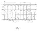
图4是说明本发明应用于谐振型直流/直流变换器的控制器较佳实施例的多数信号的波形的示意图。 FIG. 4 is a schematic diagram illustrating waveforms of most signals of a preferred embodiment of the controller applied to a resonant DC/DC converter according to the present invention. the
具体实施方式Detailed ways
为了更进一步阐述本发明为达成预定发明目的所采取的技术手段及其功效,以下结合附图及较佳实施例,对依据本发明提出的应用于谐振型直流/直流变换器的控制器其具体实施方式、结构、特征及其功效,详细说明如后。 In order to further explain the technical means and effects of the present invention to achieve the intended purpose of the invention, in conjunction with the accompanying drawings and preferred embodiments, the controller for the resonant DC/DC converter proposed according to the present invention will be described in detail below. Embodiments, structures, features and effects thereof are described in detail below. the
有关本发明的前述及其他技术内容、特点及功效,在以下配合参考图式的较佳实施例的详细说明中将可清楚呈现。通过具体实施方式的说明,当可对本发明为达成预定目的所采取的技术手段及功效得一更加深入且具体的了解,然而所附图式仅是提供参考与说明之用,并非用来对本发明加以限制。 The aforementioned and other technical contents, features and effects of the present invention will be clearly presented in the following detailed description of preferred embodiments with reference to the drawings. Through the description of the specific implementation mode, when the technical means and functions adopted by the present invention to achieve the predetermined purpose can be obtained a deeper and more specific understanding, but the accompanying drawings are only for reference and description, and are not used to explain the present invention be restricted. the
请参阅图3所示,是说明本发明应用于谐振型直流/直流变换器的控制器较佳实施例的架构示意图。本发明较佳实施例的应用于谐振型直流/直流变换器2的控制器3,包含一脉宽调制控制单元31、一高频定频信号产生单元32以及一逻辑合成单元33,其作用是用以控制谐振型直流/直流变换器2的两个切换开关21、22,以使谐振型直流/直流变换器2的输出电压Vo符合所要求。 Please refer to FIG. 3 , which is a structural diagram illustrating a preferred embodiment of the controller applied to the resonant DC/DC converter of the present invention. The
在本实施例中,谐振型直流/直流变换器2,是属于半桥对称电感电感电容(LLC)型,其元件除了两个切换开关21、22,还包括一个电容23、一个谐振电感24、一个变压器25及位于变压器25二次侧的两个同步整流管26、27,由于此电路为现有的电路,所以在此不再详述它的构造及功能。当然,除了半桥对称电感电感电容(LLC)型的变换器2,其它如不对称电感电感电容(LLC)、全桥电感电感电容(LLC)、半桥对称电感电容(LC)、不对称电感电容(LC)或全桥电感电容(LC)型的变换器,都是本发明可以应用的范畴。 In this embodiment, the resonant DC/
上述的脉宽调制控制单元31,是用以检测谐振型直流/直流变换器2的输出电压Vo及谐振电流,以产生一个如图4(I)所示的脉宽调制信号,并将此脉宽调制信号传送给高频定频信号产生单元32与逻辑合成单元33。 The above-mentioned pulse width
上述的高频定频信号产生单元32,请结合参阅图4所示,是说明本发明应用于谐振型直流/直流变换器的控制器较佳实施例的多数信号的波形的示意图,高频定频信号产生单元32接收到此脉宽调制信号后,即以脉宽调制信号的上升沿为同步信号产生一个如图4(II)所示的第一高频定频信号,并将此第一高频定频信号传送给逻辑合成单元33。 The above-mentioned high-frequency fixed-frequency signal generation unit 32, please refer to shown in Fig. 4, is the schematic diagram of the waveform of most signals that illustrate the present invention is applied to the controller preferred embodiment of resonant DC/DC converter, high-frequency constant frequency After the frequency signal generating unit 32 receives the pulse width modulation signal, it generates a first high frequency fixed frequency signal as shown in Figure 4 (II) with the rising edge of the pulse width modulation signal as a synchronous signal, and sends this first The high-frequency fixed-frequency signal is sent to the
上述的逻辑合成单元33,接收到此第一高频定频信号后,首先产生一个与第一高频定频信号频率相同、高低电位相反(反相)的如图4(III)所示的第二高频定频信号,然后将第一高频定频信号及第二高频定频信号分别与脉宽调制信号作乘法合成,以产生一个如图4(IV)所示的第一驱动信号及一个如图4(V)所示的第二驱动信号并输出以分别控制切换开关21、22。 Above-mentioned
当脉宽调制控制单元31检测到谐振型直流/直流变换器2的输出电压太小时,便增加脉宽调制信号的高电位脉波宽度(由于脉宽调制信号的周期固定,所以低电位的脉波宽度就相对应地变窄),使得切换开关21、22在每个脉宽调制信号的周期中的导通时间增加,如此就能够提高谐振型直流/直流变换器2的输出电压。相反地,当脉宽调制控制单元31检测到谐振型直流/直流变换器2的输出电压太高时,只要把脉宽调制信号的高电位脉波宽度减少,使得切换开关21、22在每个脉宽调制信号的周期中的导通时间减少,就可以降低谐振型直流/直流变换器2的输出电压,借此可以使输出电压维持在一定值。 When the pulse width
由上述说明可知,脉宽调制控制单元31只检测谐振型直流/直流变换器2的输出电压就可据以调制脉宽调制信号的脉波宽度,此外,更佳地,脉宽调制控制单元31也可同时检测谐振型直流/直流变换器2的谐振电流,以得到如图4(VI)所示的谐振电流,并同时根据谐振电流和输出电压来产生脉宽调制信号,例如可以用谐振电流和输出电压的误差调节量相比,形成双环控制,达到调制脉宽调制信号的脉波宽度。 It can be seen from the above description that the pulse width
值得一提的是,脉宽调制信号的频率大约是第一高频定频信号的频率的1/10倍,但是也可以小于;而第一、第二驱动信号除了可用以驱动切换开关21、22外,也可用以驱动变压器25二次侧的同步整流管26、27,如此可简化结构设计。 It is worth mentioning that the frequency of the pulse width modulation signal is about 1/10 times the frequency of the first high-frequency fixed-frequency signal, but it can also be less than; and the first and second driving signals can be used to drive the
另外,由于本实施例是以结合定频、定宽的第一、第二高频定频信号及脉宽调制信号所产生的第一、第二驱动信号来达成对谐振型直流/直流变换器2的控制,所以保证了在所有的负载条件下谐振型直流/直流变换器2皆处于最佳工作点(即固定的谐振频率);而借由具有固定频率和脉宽的第 一、第二驱动信号来控制切换开关21、22,可以易于实现谐振电感24和变压器25等磁性元件的最佳化设计。 In addition, since this embodiment uses the first and second driving signals generated by combining the first and second high-frequency fixed-frequency signals of fixed frequency and fixed width and the pulse width modulation signal to achieve the resonant DC/
再者,请参阅图4所示,由于本实施例是以脉宽调制信号的上升沿为同步信号来产生第一高频定频信号,如此可确保在每个脉宽调制信号周期内的第一高频定频信号的首个高频脉冲宽度相同,所以可以保证谐振电流的初始状态一致,如图4(VI)所示。虽然本实施例是以脉宽调制信号的上升沿为同步信号来产生第一高频定频信号,然而,也可以脉宽调制信号的下降缘为同步信号来产生第一高频定频信号,此变化仍属本发明技术方案所涵盖的范围。 Furthermore, please refer to Fig. 4, since the present embodiment uses the rising edge of the pulse width modulation signal as a synchronous signal to generate the first high-frequency fixed-frequency signal, so it can be ensured that the The first high-frequency pulse width of a high-frequency fixed-frequency signal is the same, so the initial state of the resonant current can be guaranteed to be consistent, as shown in Figure 4(VI). Although this embodiment uses the rising edge of the pulse width modulation signal as the synchronization signal to generate the first high-frequency fixed-frequency signal, however, the falling edge of the pulse width modulation signal can also be used as the synchronization signal to generate the first high-frequency fixed-frequency signal, This change still belongs to the scope covered by the technical solution of the present invention. the
综上所述,本发明的结构简单,并且结合定频、定宽的第一、第二高频定频信号及脉宽调制信号来控制谐振型直流/直流变换器2的切换开关21、22,保证了在所有负载条件下谐振型直流/直流变换器2皆处于最佳工作点;而在简化控制器3的结构的同时,也减少了切换开关21、22的切换次数而减小了切换开关21、22的损耗,所以确实能达成本发明的目的及功效。 In summary, the structure of the present invention is simple, and the
以上所述,仅是本发明的较佳实施例而已,并非对本发明作任何形式上的限制,虽然本发明已以较佳实施例揭露如上,然而并非用以限定本发明,任何熟悉本专业的技术人员,在不脱离本发明技术方案范围内,当可利用上述揭示的技术内容作出些许更动或修饰为等同变化的等效实施例,但凡是未脱离本发明技术方案的内容,依据本发明的技术实质对以上实施例所作的任何简单修改、等同变化与修饰,均仍属于本发明技术方案的范围内。 The above description is only a preferred embodiment of the present invention, and does not limit the present invention in any form. Although the present invention has been disclosed as above with preferred embodiments, it is not intended to limit the present invention. Anyone familiar with this field Those skilled in the art, without departing from the scope of the technical solution of the present invention, can use the technical content disclosed above to make some changes or modify equivalent embodiments with equivalent changes, but all the content that does not depart from the technical solution of the present invention, according to the present invention Any simple modifications, equivalent changes and modifications made to the above embodiments by the technical essence still belong to the scope of the technical solutions of the present invention. the
Claims (6)
Priority Applications (1)
| Application Number | Priority Date | Filing Date | Title |
|---|---|---|---|
| CN2008100071139ACN101499724B (en) | 2008-01-31 | 2008-01-31 | Controller for Resonant DC/DC Converter |
Applications Claiming Priority (1)
| Application Number | Priority Date | Filing Date | Title |
|---|---|---|---|
| CN2008100071139ACN101499724B (en) | 2008-01-31 | 2008-01-31 | Controller for Resonant DC/DC Converter |
Publications (2)
| Publication Number | Publication Date |
|---|---|
| CN101499724A CN101499724A (en) | 2009-08-05 |
| CN101499724Btrue CN101499724B (en) | 2011-06-29 |
Family
ID=40946637
Family Applications (1)
| Application Number | Title | Priority Date | Filing Date |
|---|---|---|---|
| CN2008100071139AExpired - Fee RelatedCN101499724B (en) | 2008-01-31 | 2008-01-31 | Controller for Resonant DC/DC Converter |
Country Status (1)
| Country | Link |
|---|---|
| CN (1) | CN101499724B (en) |
Families Citing this family (3)
| Publication number | Priority date | Publication date | Assignee | Title |
|---|---|---|---|---|
| CN102214997B (en)* | 2010-04-07 | 2013-11-06 | 光宝电子(广州)有限公司 | Control module and control method of resonant conversion device and resonant converter |
| CN107342688B (en) | 2016-04-29 | 2020-01-17 | 华为技术有限公司 | A resonant power converter and its frequency tracking method |
| CN107666244B (en)* | 2016-07-29 | 2020-11-27 | 中兴通讯股份有限公司 | Control method and device of resonant converter |
Citations (3)
| Publication number | Priority date | Publication date | Assignee | Title |
|---|---|---|---|---|
| CN1222266A (en)* | 1996-06-06 | 1999-07-07 | 株式会社I-Hits研究所 | AC/AC converter |
| CN1595780A (en)* | 2003-09-08 | 2005-03-16 | 艾默生网络能源有限公司 | Control method and apparatus for series resonance DC/DC converter |
| CN1992493A (en)* | 2005-12-30 | 2007-07-04 | 艾默生网络能源系统有限公司 | Resonant DC/DC converter and control method thereof |
- 2008
- 2008-01-31CNCN2008100071139Apatent/CN101499724B/ennot_activeExpired - Fee Related
Patent Citations (3)
| Publication number | Priority date | Publication date | Assignee | Title |
|---|---|---|---|---|
| CN1222266A (en)* | 1996-06-06 | 1999-07-07 | 株式会社I-Hits研究所 | AC/AC converter |
| CN1595780A (en)* | 2003-09-08 | 2005-03-16 | 艾默生网络能源有限公司 | Control method and apparatus for series resonance DC/DC converter |
| CN1992493A (en)* | 2005-12-30 | 2007-07-04 | 艾默生网络能源系统有限公司 | Resonant DC/DC converter and control method thereof |
Also Published As
| Publication number | Publication date |
|---|---|
| CN101499724A (en) | 2009-08-05 |
Similar Documents
| Publication | Publication Date | Title |
|---|---|---|
| TW200934080A (en) | Controller for use in resonant direct current/direct current converter | |
| CN110401350B (en) | Phase-shift control method for full-load range ZVS of double-active full-bridge bidirectional DC-DC converter | |
| CN101154891B (en) | Resonant converter and synchronous rectification driving method thereof | |
| CN110601543B (en) | Wide gain control method of LLC resonant converter and resonant converter thereof | |
| CN1992493B (en) | Resonance DC/DC converter and control method thereof | |
| WO2016150245A1 (en) | Dc/dc converter | |
| TW200814503A (en) | Resonance converter and driving method for synchronous rectifier thereof | |
| CN101247072A (en) | voltage regulation circuit | |
| CN101291110A (en) | Resonant converter system with relatively better efficiency and control method thereof | |
| CN101777844A (en) | Resonant converter with phase-shifted output path | |
| CN101873071A (en) | A method for minimum modulation of inductor current ripple in full-bridge-Boost DC converters | |
| CN101499724B (en) | Controller for Resonant DC/DC Converter | |
| CN112202338A (en) | Transient control method for power commutation of double-active full-bridge direct-current converter | |
| CN102611287B (en) | Method for realizing full-bridge ZVS (Zero Voltage Switch) and ZCS (Zero Current Switch) drive and circuit thereof | |
| CN110572041B (en) | A dual-side PWM plus phase-shift control method for dual active full-bridge converters | |
| CN118677265A (en) | Novel voltage-doubling rectifying wide-gain CLLC resonant converter and control method thereof | |
| TW200814517A (en) | Control circuit of multi-channels power converter | |
| CN109194135A (en) | A kind of adaptive efficiency optimization method of resonant state adjustable type power inverter | |
| CN202218160U (en) | An Auxiliary Dual-Transistor Active-Clamp Full-Bridge Soft-Switching Converter | |
| CN103956930B (en) | A kind of frequency modulating method for full bridge inverter | |
| CN113726167B (en) | Mixed fixed-frequency modulation method with wide output gain range | |
| WO2018157797A1 (en) | Full-bridge resonant converter | |
| CN202872641U (en) | Double bridge phase shift series-parallel resonance high-voltage direct-current power source | |
| CN102969928B (en) | Output power adjustment method for resonance type converter | |
| CN119834626A (en) | General transient direct current bias suppression method under bidirectional power flow of double-active bridge converter |
Legal Events
| Date | Code | Title | Description |
|---|---|---|---|
| C06 | Publication | ||
| PB01 | Publication | ||
| C10 | Entry into substantive examination | ||
| SE01 | Entry into force of request for substantive examination | ||
| C14 | Grant of patent or utility model | ||
| GR01 | Patent grant | ||
| C41 | Transfer of patent application or patent right or utility model | ||
| TR01 | Transfer of patent right | Effective date of registration:20170222 Address after:Wujin, Changzhou province high tech Industrial Development Zone, 88 Yang Lake Road, No. Patentee after:LITE-ON Technology (Chang Zhou) Co.,Ltd. Patentee after:Lite-On Technology Co.,Ltd. Address before:Taipei City, Taiwan, China Patentee before:Lite-On Technology Co.,Ltd. | |
| CF01 | Termination of patent right due to non-payment of annual fee | Granted publication date:20110629 Termination date:20220131 | |
| CF01 | Termination of patent right due to non-payment of annual fee |