CN101499334A - Optical-electrical composite transmission device and electronic equipment - Google Patents
Optical-electrical composite transmission device and electronic equipmentDownload PDFInfo
- Publication number
- CN101499334A CN101499334ACNA200910001648XACN200910001648ACN101499334ACN 101499334 ACN101499334 ACN 101499334ACN A200910001648X ACNA200910001648X ACN A200910001648XACN 200910001648 ACN200910001648 ACN 200910001648ACN 101499334 ACN101499334 ACN 101499334A
- Authority
- CN
- China
- Prior art keywords
- optical
- transmission device
- electrical composite
- composite transmission
- optical fiber
- Prior art date
- Legal status (The legal status is an assumption and is not a legal conclusion. Google has not performed a legal analysis and makes no representation as to the accuracy of the status listed.)
- Granted
Links
Images


Classifications
- G—PHYSICS
- G02—OPTICS
- G02B—OPTICAL ELEMENTS, SYSTEMS OR APPARATUS
- G02B6/00—Light guides; Structural details of arrangements comprising light guides and other optical elements, e.g. couplings
- G02B6/44—Mechanical structures for providing tensile strength and external protection for fibres, e.g. optical transmission cables
- G02B6/4401—Optical cables
- G02B6/4415—Cables for special applications
- G02B6/4416—Heterogeneous cables
- G—PHYSICS
- G02—OPTICS
- G02B—OPTICAL ELEMENTS, SYSTEMS OR APPARATUS
- G02B6/00—Light guides; Structural details of arrangements comprising light guides and other optical elements, e.g. couplings
- G02B6/24—Coupling light guides
- G02B6/42—Coupling light guides with opto-electronic elements
- G02B6/43—Arrangements comprising a plurality of opto-electronic elements and associated optical interconnections
Landscapes
- Physics & Mathematics (AREA)
- General Physics & Mathematics (AREA)
- Optics & Photonics (AREA)
- Light Guides In General And Applications Therefor (AREA)
- Optical Integrated Circuits (AREA)
- Optical Couplings Of Light Guides (AREA)
- Structure Of Printed Boards (AREA)
Abstract
Translated fromChinese
Description
Translated fromChinese技术领域technical field
本发明涉及光电复合传送装置及具备其的电子设备,涉及一种光电复合传送装置,适用于例如小型且节省空间为必要条件的便携设备内部的配线。The present invention relates to a photoelectric composite transmission device and an electronic device equipped therewith, and relates to a photoelectric composite transmission device suitable for wiring inside a portable device, for example, where small size and space saving are essential requirements.
背景技术Background technique
近年来,在手机的显示部和操作部之间的通信中,通过密封柔性电缆来应对干扰音的问题(参照日本特开2001-119460号公报)。In recent years, in the communication between the display unit and the operation unit of the mobile phone, the problem of noise noise has been solved by sealing flexible cables (see Japanese Patent Application Laid-Open No. 2001-119460).
但是,处理更加高精细的运动图像时,传输的信号必然高速化,伴随着该传输的高速化,出现产生电磁波干扰的问题。并且,在用于手机之类的空间有限的设备的情况下,通过密封所述柔性电缆的电磁波对策存在构造复杂且尺寸变大的问题。However, when processing higher-definition moving images, the speed of the transmitted signal must be increased, and with this increased speed of transmission, there is a problem that electromagnetic wave interference occurs. In addition, when used in a device with limited space such as a mobile phone, the electromagnetic wave countermeasure by sealing the flexible cable has a problem that the structure is complicated and the size becomes large.
因此,关于这种高速信号的传输,提出通过光进行通信的建议(参照日本特开2007-267358号公报)。然而,即使是光通信时,连接显示部的电源线及接地线需要传输电信号。Therefore, communication by light has been proposed for such high-speed signal transmission (see Japanese Patent Application Laid-Open No. 2007-267358). However, even in the case of optical communication, the power line and the ground line connected to the display unit need to transmit electrical signals.
这样,提出使用以皮膜将电源用电缆和传输光信号的光缆包覆为一根线的光电复合缆线(参照日本特开2002-237226号公报)、或是利用了光波导的光电复合信号缆线(参照日本特开平6-281831号公报)。In this way, it has been proposed to use a photoelectric composite cable in which a power supply cable and an optical cable for transmitting optical signals are covered with a film (see Japanese Patent Application Laid-Open No. 2002-237226 ), or a photoelectric composite signal cable using an optical waveguide. line (refer to Japanese Patent Application Laid-Open No. 6-281831).
但是,所述光电复合缆线存在以下问题。However, the photoelectric composite cable has the following problems.
(i)由于电信号传输部和光信号传输部的材料不同,当施加拉伸力之类的应力时,应力向强度较弱的位置集中。(i) Since the materials of the electrical signal transmission part and the optical signal transmission part are different, when a stress such as a tensile force is applied, the stress concentrates on a weaker position.
(ii)因为电信号传输部和光信号传输部的材料的不同,由于电信号传输部和光信号传输部的热膨胀系数的不同,高温时或低温时可能发生信号线的变形。(ii) Because of the difference in material of the electrical signal transmission part and the optical signal transmission part, deformation of the signal line may occur at high temperature or low temperature due to the difference in thermal expansion coefficient of the electrical signal transmission part and the optical signal transmission part.
(iii)光电复合缆线的制造成本高。(iii) The manufacturing cost of the photoelectric composite cable is high.
并且,当将电信号传输部和光信号传输部分离时,由于双方的弯曲性不同,存在线散乱等问题。其结果,可能难以实现节省空间的目的。In addition, when the electrical signal transmission part and the optical signal transmission part are separated, there are problems such as scattered wires due to the difference in bendability between the two. As a result, it may be difficult to achieve space saving.
并且,关于手机,由于近年来小型化、薄型化的发展,例如,对于具备铰接部的折叠式的手机,要求在构造上将信号线控制在大约直径3mm之内。In addition, with regard to mobile phones, due to the development of miniaturization and thinning in recent years, for example, for foldable mobile phones with hinges, it is required to control the signal line within about 3 mm in diameter structurally.
发明内容Contents of the invention
本发明是为解决所述问题中的至少一项而作出的。The present invention has been made to solve at least one of the problems.
本发明的光电复合传送装置具备光信号传输部件和电信号传输部件。所述光信号传输部件和电信号传输部件以不分离的方式被一体化。The photoelectric composite transmission device of the present invention includes an optical signal transmission unit and an electrical signal transmission unit. The optical signal transmission part and the electric signal transmission part are integrated in a non-separated manner.
根据本发明,由于所述光信号传输部件和所述电信号传输部件以不分离的方式被一体化,可以避免由于双方弯曲性的不同而产生的线散乱等问题。其结果,可以达到节省空间的目的。该结果使该光电复合传送装置可以搭载于手机等小型设备上,能够进行这种小型设备的高速信号传输及电源线、接地线的信号传输。According to the present invention, since the optical signal transmission part and the electric signal transmission part are integrated without being separated, it is possible to avoid problems such as wire scatter due to differences in bendability between the two. As a result, space saving can be achieved. As a result, the photoelectric composite transmission device can be mounted on small devices such as mobile phones, and can perform high-speed signal transmission of such small devices and signal transmission of power lines and ground lines.
并且,在一实施例中,所述光信号传输部件为光纤,所述电信号传输部件为柔性基板。Moreover, in an embodiment, the optical signal transmission component is an optical fiber, and the electrical signal transmission component is a flexible substrate.
根据该实施例,能够实现具备柔软的弯曲性、可节省空间且低价的光电复合缆线。According to this embodiment, it is possible to realize a flexible, space-saving, and inexpensive photoelectric composite cable.
在一实施例中,在所述柔性基板上形成的多个孔中插入所述光纤。In one embodiment, the optical fibers are inserted into a plurality of holes formed on the flexible substrate.
根据该实施例,运用简单的构造可以实现将柔性基板和光纤以不分离的方式一体化。According to this embodiment, the integration of the flexible substrate and the optical fiber without separation can be realized with a simple structure.
在一实施例中,将所述多个孔沿所述柔性基板的延伸方向配置为锯齿状。In an embodiment, the plurality of holes are arranged in a zigzag shape along the extending direction of the flexible substrate.
根据该实施例,运用简单的构造可以实现将柔性基板和光缆以不分离的方式更加坚固地一体化。According to this embodiment, a more robust integration of the flexible substrate and the optical cable without separation can be realized with a simple structure.
在一实施例中,所述柔性基板具有多个安装部。在所述安装部上分别形成的孔中插入所述光纤。各安装部上设置的孔的数量可以是一个,也可以是两个以上。In one embodiment, the flexible substrate has a plurality of mounting portions. The optical fibers are inserted into holes respectively formed on the mounting parts. The number of holes provided on each mounting portion may be one or more than two.
在柔性基板具有的配线部的宽度相对于柔性基板的宽度相对较宽、在柔性基板的配线部以外的部分上难以形成孔时,该实施例是有效的。This embodiment is effective when the width of the wiring portion of the flexible substrate is relatively wider than that of the flexible substrate and it is difficult to form holes in portions other than the wiring portion of the flexible substrate.
在一实施例中,所述光电复合传送装置具备另外的柔性基板。运用该另外的柔性基板和作为所述电信号传输部件的所述柔性基板夹持所述光纤来实现一体化。In one embodiment, the photoelectric composite transmission device includes another flexible substrate. The optical fiber is sandwiched by the additional flexible substrate and the flexible substrate as the electrical signal transmission part to achieve integration.
根据该实施例,运用简单的构造可以实现将柔性基板和光纤以不分离的方式更加坚固地一体化。而且,所述另一块柔性基板也能够作为电信号传输部件使用。According to this embodiment, the flexible substrate and the optical fiber can be more firmly integrated without separation with a simple structure. Moreover, the other flexible substrate can also be used as an electrical signal transmission component.
在一实施例中,所述光纤呈螺旋状缠绕在所述柔性基板上。In one embodiment, the optical fiber is helically wound on the flexible substrate.
根据该实施例,由于可以调整光纤的卷绕圈数,就不要求光纤的长度的精度。According to this embodiment, since the number of turns of the optical fiber can be adjusted, the accuracy of the length of the optical fiber is not required.
在一实施例中,在所述柔性基板上形成的多个缺口部中嵌入所述光纤。In one embodiment, the optical fibers are embedded in a plurality of notches formed on the flexible substrate.
根据该实施例,可以通过更加简单的构造实现柔性基板和光纤的一体化。According to this embodiment, the integration of the flexible substrate and the optical fiber can be realized with a simpler configuration.
在一实施例中,所述光纤是塑料光纤。In one embodiment, said optical fiber is a plastic optical fiber.
在一实施例中,所述光纤是塑料包层石英光纤。In one embodiment, the optical fiber is a plastic clad silica optical fiber.
在一实施例中,所述光纤是玻璃光纤。In one embodiment, said optical fiber is a glass optical fiber.
在一实施例中,所述光纤是多芯光纤。In one embodiment, said optical fiber is a multi-core optical fiber.
在一实施例中,所述光信号传输部件是具有光波导的波导基板。所述电信号传输部件是电线。In one embodiment, the optical signal transmission component is a waveguide substrate having an optical waveguide. The electrical signal transmission component is an electric wire.
根据该实施例,由于采用运用例如聚酰亚胺等树脂制成的波导基板,能够实现具备柔软的弯曲性、可节省空间且低价的光电复合缆线。According to this embodiment, since a waveguide substrate made of resin such as polyimide is used, a flexible, space-saving, and inexpensive photoelectric composite cable can be realized.
在一实施例中,在所述波导基板上形成的多个孔中插入所述电线。In one embodiment, the wires are inserted into a plurality of holes formed on the waveguide substrate.
根据该实施例,通过简单的构造可以实现将波导基板和电线以不分离的方式一体化。According to this embodiment, integration of the waveguide substrate and electric wires without separation can be realized with a simple configuration.
在一实施例中,将所述多个孔沿所述波导基板的延伸方向配置为锯齿状。In an embodiment, the plurality of holes are arranged in a zigzag shape along the extending direction of the waveguide substrate.
根据该实施例,通过简单的构造可以实现将波导基板和电线以不分离的方式更加坚固地一体化。According to this embodiment, the waveguide substrate and the electric wire can be more firmly integrated without being separated by a simple structure.
在一实施例中,所述波导基板具有多个安装部。在所述安装部上分别形成的孔中插入所述电线。各安装部上设置的孔的数量可以是一个,也可以是两个以上。In one embodiment, the waveguide substrate has a plurality of mounting portions. The electric wires are inserted into holes respectively formed on the mounting parts. The number of holes provided on each mounting portion may be one or more than two.
在波导基板具有的光波导部的宽度相对于波导基板的宽度相对较宽、在波导基板的光波导部以外的部分上难以形成孔时,该实施例是有效的。This embodiment is effective when the width of the optical waveguide portion of the waveguide substrate is relatively wider than that of the waveguide substrate and it is difficult to form holes in portions other than the optical waveguide portion of the waveguide substrate.
在一实施例中,所述光电复合传送装置具备另外的波导基板。通过该另外的波导基板和作为所述光信号传输部件的所述波导基板夹持所述电线来实现一体化。In one embodiment, the photoelectric composite transmission device includes another waveguide substrate. Integration is achieved by sandwiching the electric wires between the separate waveguide substrate and the waveguide substrate as the optical signal transmission member.
根据该实施例,运用简单的构造可以实现将波导基板和电线以不分离的方式更加坚固地一体化。而且,所述另外的波导基板也能够作为光信号传输部件使用。According to this embodiment, with a simple structure, the waveguide substrate and the electric wire can be more firmly integrated without being separated. Furthermore, the other waveguide substrate can also be used as an optical signal transmission member.
在一实施例中,所述电线呈螺旋状缠绕在所述所述波导基板上。In one embodiment, the electric wires are helically wound on the waveguide substrate.
根据该实施例,由于可以调整电线的卷绕的圈数,不再要求电线长度的精度。According to this embodiment, since the number of turns of the electric wire can be adjusted, the accuracy of the electric wire length is no longer required.
在一实施例中,在所述波导基板上形成的多个缺口部中嵌入所述电线。In one embodiment, the wires are embedded in a plurality of notches formed on the waveguide substrate.
根据该实施例,能够运用更加简单的构造实现波导基板和电线的一体化。According to this embodiment, it is possible to realize the integration of the waveguide substrate and the electric wire with a simpler structure.
在一实施例中,所述光电复合传送装置是能够穿过直径3mm以下的孔的光电复合缆线。In one embodiment, the photoelectric composite transmission device is a photoelectric composite cable capable of passing through a hole with a diameter of 3 mm or less.
该实施例中的光电复合传送装置适用于例如具有铰接部的折叠式手机。The photoelectric composite transmission device in this embodiment is suitable for, for example, a folding mobile phone having a hinge.
由于一实施例的电子设备具备将所述光信号传输部件和电信号传输部件以不分离的方式一体化的光电复合传送装置,能够进行高速信号传输及电源线、接地线的信号传输,同时,也能够实现小型化、节省空间。Since the electronic equipment in one embodiment is equipped with a photoelectric composite transmission device that integrates the optical signal transmission component and the electrical signal transmission component in a non-separated manner, it can perform high-speed signal transmission and signal transmission of power lines and ground lines. At the same time, It is also possible to achieve miniaturization and space saving.
本发明通过以下的详细说明和附图应该可以更加充分地被理解。附图仅仅是为了说明,并不限制本发明。The present invention should be understood more fully by the following detailed description and accompanying drawings. The drawings are for illustration only and do not limit the invention.
附图说明Description of drawings
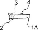
图1A~1C是示意性地表示作为本发明的光电复合传送装置的第一实施例的光电复合缆线的图。图1A是平面图、图1B是图1A的1B-1B线的截面图、图1C是将该光电复合缆线绕平行于轴向的线而弯曲时的端面图。1A to 1C are diagrams schematically showing a photoelectric composite cable as a first embodiment of the photoelectric composite transmission device of the present invention. 1A is a plan view, FIG. 1B is a cross-sectional view along line 1B-1B of FIG. 1A , and FIG. 1C is an end view when the photoelectric composite cable is bent around a line parallel to the axial direction.
图2A~2C是示意性地表示作为本发明的光电复合传送装置的第二实施例的光电复合缆线的图。图2A是平面图、图2B是截面图、图2C是将该光电复合缆线绕平行于轴向的线而弯曲时的端面图。2A to 2C are diagrams schematically showing a photoelectric composite cable as a second embodiment of the photoelectric composite transmission device of the present invention. 2A is a plan view, FIG. 2B is a cross-sectional view, and FIG. 2C is an end view when the photoelectric composite cable is bent around a line parallel to the axial direction.
图3A~3C是示意性地表示作为本发明的光电复合传送装置的第三实施例的光电复合缆线的图。图3A是平面图、图3B是截面图、图3C是将该光电复合缆线绕平行于轴向的线而弯曲时的端面图。3A to 3C are diagrams schematically showing a photoelectric composite cable as a third embodiment of the photoelectric composite transmission device of the present invention. 3A is a plan view, FIG. 3B is a cross-sectional view, and FIG. 3C is an end view when the photoelectric composite cable is bent around a line parallel to the axial direction.
图4A~4C是示意性地表示作为本发明的光电复合传送装置的第四实施例的光电复合缆线的图。图4A是平面图、图4B是截面图、图4C是将该光电复合缆线绕平行于轴向的线而弯曲时的端面图。4A to 4C are diagrams schematically showing a photoelectric composite cable as a fourth embodiment of the photoelectric composite transmission device of the present invention. 4A is a plan view, FIG. 4B is a cross-sectional view, and FIG. 4C is an end view when the photoelectric composite cable is bent around a line parallel to the axial direction.
图5A~5C是示意性地表示作为该发明的光电复合传送装置的第五实施例的光电复合缆线的图。图5A是平面图、图5B是截面图、图5C是将该光电复合缆线绕平行于轴向的线而弯曲时的端面图。5A to 5C are diagrams schematically showing a photoelectric composite cable as a fifth embodiment of the photoelectric composite transmission device of the present invention. 5A is a plan view, FIG. 5B is a cross-sectional view, and FIG. 5C is an end view when the photoelectric composite cable is bent around a line parallel to the axial direction.
图6A~6C是示意性地表示作为本发明的光电复合传送装置的第六实施例的光电复合缆线的图。图6A是平面图、图6B是截面图、图6C是将该光电复合缆线绕平行轴向的线而弯曲时的端面图。6A to 6C are diagrams schematically showing a photoelectric composite cable as a sixth embodiment of the photoelectric composite transmission device of the present invention. 6A is a plan view, FIG. 6B is a cross-sectional view, and FIG. 6C is an end view when the photoelectric composite cable is bent around a line parallel to the axial direction.
图7A~7C是示意性地表示作为本发明的光电复合传送装置的第七实施例的光电复合缆线的图。图7A是平面图、图7B是截面图、图7C是将该光电复合缆线绕平行于轴向的线而弯曲时的端面图。7A to 7C are diagrams schematically showing a photoelectric composite cable as a seventh embodiment of the photoelectric composite transmission device of the present invention. 7A is a plan view, FIG. 7B is a cross-sectional view, and FIG. 7C is an end view when the photoelectric composite cable is bent around a line parallel to the axial direction.
图8A~8C是示意性地表示作为本发明的光电复合传送装置的第八实施例的光电复合缆线的图。图8A是平面图、图8B是截面图、图8C是将该光电复合缆线绕平行于轴向的线而弯曲时的端面图。8A to 8C are diagrams schematically showing a photoelectric composite cable as an eighth embodiment of the photoelectric composite transmission device of the present invention. 8A is a plan view, FIG. 8B is a cross-sectional view, and FIG. 8C is an end view when the photoelectric composite cable is bent around a line parallel to the axial direction.
图9A~9C是示意性地表示作为本发明的光电复合传送装置的第九实施例的光电复合缆线的图。图9A是平面图、图9B是截面图、图9C是将该光电复合缆线绕平行于轴向的线而弯曲时的端面图。9A to 9C are diagrams schematically showing a photoelectric composite cable as a ninth embodiment of the photoelectric composite transmission device of the present invention. 9A is a plan view, FIG. 9B is a cross-sectional view, and FIG. 9C is an end view when the photoelectric composite cable is bent around a line parallel to the axial direction.
图10A~10C是示意性地表示作为本发明的光电复合传送装置的第十实施例的光电复合缆线的图。图10A是平面图、图10B是截面图、图10C是将该光电复合缆线绕平行于轴向的线而弯曲时的端面图。10A to 10C are diagrams schematically showing a photoelectric composite cable as a tenth embodiment of the photoelectric composite transmission device of the present invention. 10A is a plan view, FIG. 10B is a cross-sectional view, and FIG. 10C is an end view when the photoelectric composite cable is bent around a line parallel to the axial direction.
图11A~11C是示意性地表示作为本发明的光电复合传送装置的第十一实施例的光电复合缆线的图。图11A是平面图、图11B是截面图、图11C是将该光电复合缆线绕平行于轴向的线而弯曲时的端面图。11A to 11C are diagrams schematically showing a photoelectric composite cable as an eleventh embodiment of the photoelectric composite transmission device of the present invention. 11A is a plan view, FIG. 11B is a cross-sectional view, and FIG. 11C is an end view when the photoelectric composite cable is bent around a line parallel to the axial direction.
图12A~12C是示意性地表示作为本发明的光电复合传送装置的第十二实施例的光电复合缆线的图。图12A是平面图、图12B是截面图、图12C是将该光电复合缆线绕平行于轴向的线而弯曲时的端面图。12A to 12C are diagrams schematically showing a photoelectric composite cable as a twelfth embodiment of the photoelectric composite transmission device of the present invention. 12A is a plan view, FIG. 12B is a cross-sectional view, and FIG. 12C is an end view when the photoelectric composite cable is bent around a line parallel to the axial direction.
具体实施方式Detailed ways
下面,通过图示的实施例对该发明进行详细的说明。Hereinafter, this invention will be described in detail with reference to illustrated embodiments.
(第一实施例)(first embodiment)
图1A是示意性地表示作为本发明的光电复合传送装置的第一实施例的光电复合缆线的平面图、图1B是图1A的1B-1B线的截面图。在图1B中,为了使图简单化省略了剖面线(也适用于表示截面图的其他图)。1A is a plan view schematically showing a photoelectric composite cable as a first embodiment of the photoelectric composite transmission device of the present invention, and FIG. 1B is a cross-sectional view taken along line 1B-1B of FIG. 1A . In FIG. 1B , hatching is omitted for the sake of simplification of the drawing (this applies also to other figures showing cross-sectional views).
该第一实施例的光电复合缆线,包括,作为具有电配线部4的电信号传输部件的柔性基板1、作为光信号传输部件的光纤2。该光纤2以缝缀树脂制基部1A的方式插入到柔性基板1的树脂制基部1A上形成的数个孔3中。该光纤2和柔性基板1构成复合缆线。并且,所述电配线部4形成电信号线或电源线。The photoelectric composite cable of the first embodiment includes a flexible substrate 1 as an electrical signal transmission member having an
根据该第一实施例的光电复合缆线,作为电信号传输部件的柔性基板1和作为光信号传输部件的光纤2以不分离的方式被一体化,形成即使柔性基板1和光纤2各自形成的传送线路的特性(拉伸强度、热膨胀系数)不同,作为一个整体也具备稳定的弯曲性的光电复合缆线。According to the photoelectric composite cable of this first embodiment, the flexible substrate 1 as an electrical signal transmission part and the
另外,当该光电复合缆线穿过直径3mm以下的孔时,如图1C所示,通过将光电复合缆线绕平行于其轴向的线弯曲,可以使光电复合缆线的实际直径在3mm以下。因此,该实施例的光电复合缆线可以作为适用于例如具有铰接部的折叠式手机的光电复合传送装置。后述的其他实施例的光电复合传送装置也同样适用。In addition, when the photoelectric composite cable passes through a hole with a diameter of 3 mm or less, as shown in Figure 1C, the actual diameter of the photoelectric composite cable can be made within 3 mm by bending the photoelectric composite cable around a line parallel to its axial direction. the following. Therefore, the photoelectric composite cable of this embodiment can be used as a photoelectric composite transmission device suitable for, for example, a folding mobile phone having a hinge. The same applies to photoelectric composite transmission devices of other embodiments described later.
(第二实施例)(second embodiment)
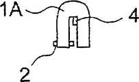
其次,图2A及2B是示意性地表示作为本发明的光电复合传送装置的第二实施例的光电复合缆线的平面图及截面图。图2C表示所述光电复合缆线穿过直径3mm以下的孔时的形状。Next, FIGS. 2A and 2B are plan views and cross-sectional views schematically showing a photoelectric composite cable as a second embodiment of the photoelectric composite transmission device of the present invention. FIG. 2C shows the shape of the photoelectric composite cable when it passes through a hole with a diameter of 3 mm or less.
该第二实施例的光电复合缆线,在具有电配线部24的柔性基板21的树脂制基部21A上将光纤2穿过的孔23配置为锯齿状;通过在该配置为锯齿状的多个孔23上以缝缀树脂制基部21A的方式插入光纤2。所述电配线部24形成例如电信号线或电源线。In the photoelectric composite cable of the second embodiment, the
该第二实施例与上述第一实施例相比,虽然光纤2的长度变长了,但是由于相对于电配线部24光纤2被左右对称地配置,所以,与第一实施例相比缆线的弯曲性好。另外,在该实施例中,虽然在所述柔性基板21的树脂制基部21A上形成的多个孔23在电配线部24的两侧逐个交替地配置为锯齿状,但是也可以在所述电配线部24的两侧以每两个以上交替的方式配置。并且,所述多个孔23不必一定配置为锯齿状,如果不对电配线部24产生影响,配置在基部21A的哪个部分都可以。In this second embodiment, compared with the above-mentioned first embodiment, although the length of the
(第三实施例)(third embodiment)
图3A及3B是示意性地表示作为该发明的光电复合传送装置的第三实施例的光电复合缆线的平面图及截面图。图3C表示所述光电复合缆线穿过直径3mm以下的孔时的形状。3A and 3B are plan views and cross-sectional views schematically showing a photoelectric composite cable as a third embodiment of the photoelectric composite transmission device of the present invention. FIG. 3C shows the shape of the photoelectric composite cable when it passes through a hole with a diameter of 3 mm or less.
该第三实施例包括:作为具有电配线部34的电信号传输部件的柔性基板31和作为光信号传输部件的光纤32。所述柔性基板31在树脂制基部31A的侧面,隔开规定的间隔形成有多个安装部35。该安装部35各自具有一个孔35A。在该孔35A里插入所述光纤32。另外,各安装部35按照其尺寸也可以有两个以上的孔35A。This third embodiment includes: a flexible substrate 31 as an electric signal transmission part having an
在该第三实施例中,因为具有将光纤32安装在柔性基板31上的安装部35,所以可以将电配线部34的宽度设定为接近柔性基板31的宽度的宽度。因此,在电配线部34的宽度必须接近柔性基板31的宽度时和想使所述柔性基板31的宽度尽量变窄时,该第三实施例是有效的。In this third embodiment, since the mounting portion 35 for mounting the
(第四实施例)(fourth embodiment)
图4A及4B是示意性地表示作为本发明的光电复合传送装置的第四实施例的光电复合缆线的平面图及截面图。图4C表示所述光电复合缆线穿过直径3mm以下的孔时的形状。4A and 4B are plan views and cross-sectional views schematically showing a photoelectric composite cable as a fourth embodiment of the photoelectric composite transmission device of the present invention. FIG. 4C shows the shape of the photoelectric composite cable when it passes through a hole with a diameter of 3 mm or less.
在该第四实施例中,用两块柔性基板41、47夹持作为光信号传输部件的光纤42,该两块柔性基板41、47用粘合剂相互粘结。所述柔性基板41具有电配线部44并构成电信号传输部件。与柔性基板41相同地,另一块柔性基板47也具有电配线部44,根据需要该柔性基板47也可以实现电信号传输部件的功能。In this fourth embodiment, an
(第五实施例)(fifth embodiment)
图5A及5B是示意性地表示作为本发明的光电复合传送装置的第五实施例的光电复合缆线的平面图及截面图。图5C表示所述光电复合缆线穿过直径3mm以下的孔时的形状。5A and 5B are plan views and cross-sectional views schematically showing a photoelectric composite cable as a fifth embodiment of the photoelectric composite transmission device of the present invention. FIG. 5C shows the shape of the photoelectric composite cable when it passes through a hole with a diameter of 3 mm or less.
该第五实施例包括:作为具有电配线部54的电信号传输部件的柔性基板51和作为光信号传输部件的光纤52。使该光纤52在所述柔性基板51的周围呈螺旋状缠绕。在该第五实施例中,虽然必须使光纤52的长度比柔性基板51的长度长,但是因为可以根据光纤52的长度增减光纤52卷绕的圈数,所以没有必要规定光纤52的长度精度。This fifth embodiment includes: a flexible substrate 51 as an electric signal transmission part having an
(第六实施例)(sixth embodiment)
图6A及6B是示意性地表示作为本发明的光电复合传送装置的第六实施例的光电复合缆线的平面图及截面图。图6C表示所述光电复合缆线穿过直径3mm以下的孔时的形状。6A and 6B are plan views and cross-sectional views schematically showing a photoelectric composite cable as a sixth embodiment of the photoelectric composite transmission device of the present invention. FIG. 6C shows the shape of the photoelectric composite cable when it passes through a hole with a diameter of 3 mm or less.
该第六实施例包括:作为具有电配线部64的电信号传输部件的柔性基板61和作为光信号传输部件的光纤62。所述柔性基板61在树脂制基部61A的单侧隔开规定的间隔形成有多个缺口部63。而且,所述光纤62以交替跨越基部61A在相邻的所述缺口部63和63之间的部分66的一侧和另一侧的方式,嵌入到所述多个缺口部63中。This sixth embodiment includes: a
另外,在该第六实施例中,虽然仅在所述柔性基板61的树脂制基部61A的单侧形成所述缺口部63,但是也可以在树脂制基部61A的两侧交替形成缺口部。此时,可以选择所述两侧的缺口部中的一侧作为嵌入所述光纤62的缺口部。而且,也可以在所述两侧的缺口部中交替地嵌入光纤62。并且,也可以在所述两侧的缺口部中分别嵌入不同的光纤。In addition, in the sixth embodiment, although the
(第七实施例)(seventh embodiment)
图7A及7B是示意性地表示作为本发明的光电复合传送装置的第七实施例的光电复合缆线的平面图及截面图。图7C表示所述光电复合缆线穿过直径3mm以下的孔时的形状。7A and 7B are plan views and cross-sectional views schematically showing a photoelectric composite cable as a seventh embodiment of the photoelectric composite transmission device of the present invention. FIG. 7C shows the shape of the photoelectric composite cable when it passes through a hole with a diameter of 3 mm or less.
该第七实施例包括:作为形成有光波导79的光信号传输部件的光波导基板77和作为电信号传输部件的电线78。在所述光波导基板77上,在光波导79的单侧沿光波导79的延伸方向隔开规定的间隔形成多个孔73。所述电线78以缝缀所述光波导基板77的基部77A的方式插入该多个孔73中。该光波导基板77和电线78构成复合缆线。并且,所述电线78形成例如电信号线或电源线。并且,所述光波导基板77由例如聚酰亚胺等树脂制成。This seventh embodiment includes: an
根据该第七实施例的光电复合缆线,作为电信号传输部件的电线78和作为光信号传输部件的光波导基板77以不分离的方式被一体化,形成即使电线78和光波导基板77各自形成的传送线路的特性(拉伸强度、热膨胀系数)不同,作为一个整体也具有稳定的弯曲性的光电复合缆线。另外,如同在所述第一实施例中说明的那样,通过将该光电复合缆线弯曲为图7C所示的形状,能够使其实际直径在3mm以下,可以容纳在小型设备内的直径3mm以下的孔中。因此,能够成为适用于具有铰接部的折叠式手机的光电复合传送装置。According to the photoelectric composite cable of this seventh embodiment, the
(第八实施例)(eighth embodiment)
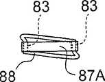
图8A及8B是示意性地表示作为本发明的光电复合传送装置的第八实施例的光电复合缆线的平面图及截面图。图8C表示所述光电复合缆线穿过直径3mm以下的孔时的形状。8A and 8B are plan views and cross-sectional views schematically showing a photoelectric composite cable as an eighth embodiment of the photoelectric composite transmission device of the present invention. FIG. 8C shows the shape of the photoelectric composite cable when it passes through a hole with a diameter of 3 mm or less.
该第八实施例的光电复合缆线,在作为具有光波导89的光信号传输部件的波导基板87的基部87A上,锯齿状地形成穿过作为电信号传输部件的电线88的孔83。在该锯齿状配置的多个孔83中以缝缀基部87A的方式插入电线88。所述电线88形成例如电信号线、电源线。并且,所述光波导基板87由例如聚酰亚胺等树脂制成。In the photoelectric composite cable of the eighth embodiment, a
该第八实施例的光电复合缆线与上述第七实施例相比,虽然电线88的长度变长,但是由于相对于光波导89电线88被左右对称地配置,所以与第七实施例相比缆线的弯曲性好。In the photoelectric composite cable of the eighth embodiment, compared with the above-mentioned seventh embodiment, the length of the
另外,在实施例中,虽然将在波导基板87的基部87A上形成的多个孔83逐个交替地锯齿状地配置在光波导89的两侧,但是也可以在所述光波导89的两侧以每两个以上的方式交替地配置。并且,所述多个孔83不必一定配置为锯齿状,只要不对光波导89产生影响,配置在基部87A的哪个部分都可以。In addition, in the embodiment, although the plurality of
(第九实施例)(ninth embodiment)
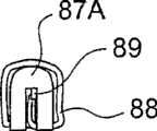
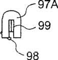
图9A及9B是示意性地表示作为该发明的光电复合传送装置的第九实施例的光电复合缆线的平面图及截面图。图9C表示所述光电复合缆线穿过直径3mm以下的孔时的形状。9A and 9B are plan views and cross-sectional views schematically showing a photoelectric composite cable as a ninth embodiment of the photoelectric composite transmission device of the present invention. FIG. 9C shows the shape of the photoelectric composite cable when it passes through a hole with a diameter of 3 mm or less.
该第九实施例包括:作为具有光波导99的光信号传输部件的波导基板97和作为电信号传输部件的电线98。在所述波导基板97上,在基部97A的侧面隔开规定的间隔形成多个安装部95。该安装部95各自具有孔95A。在该孔95A上插入所述电线98。并且,所述光波导基板97由例如聚酰亚胺等树脂制成。另外,与所述第三实施例同样地,各安装部95按照其尺寸也可以有两个以上的孔95A。This ninth embodiment includes: a
在该第九实施例中,因为具有将电线98安装在波导基板97上的安装部95,所以能够将光波导99的宽度设定为接近波导基板97的宽度。因此,在光波导99的宽度必须接近波导基板97的宽度时和想使所述波导基板97的宽度尽量变窄时,该第九实施例是有效的。In the ninth embodiment, since the mounting
(第十实施例)(tenth embodiment)
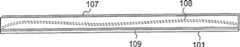
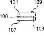
图10A及10B是示意性地表示作为本发明的光电复合传送装置的第十实施例的光电复合缆线的平面图及截面图。图10C表示所述光电复合缆线穿过直径3mm以下的孔时的形状。10A and 10B are plan views and cross-sectional views schematically showing a photoelectric composite cable as a tenth embodiment of the photoelectric composite transmission device of the present invention. FIG. 10C shows the shape of the photoelectric composite cable when it passes through a hole with a diameter of 3 mm or less.
在该第十实施例中,用两块波导基板101、107夹持作为电信号传输部件的电线108,用粘合剂将该两片波导基板101、107相互粘接。所述波导基板101具有光波导109并构成光信号传输部件。与波导基板101相同地,另一块波导基板107也具有光波导109,根据需要,该波导基板107也可以实现光信号传输部件的功能。并且,所述光波导基板101、107由例如聚酰亚胺等树脂制成。In the tenth embodiment, an
(第十一实施例)(eleventh embodiment)
图11A及11B是示意性地表示作为本发明的光电复合传送装置的第十一实施例的光电复合缆线的平面图及截面图。图11C表示所述光电复合缆线穿过直径3mm以下的孔时的形状。11A and 11B are plan views and cross-sectional views schematically showing a photoelectric composite cable as an eleventh embodiment of the photoelectric composite transmission device of the present invention. FIG. 11C shows the shape of the photoelectric composite cable when it passes through a hole with a diameter of 3 mm or less.
该第十一实施例包括:作为具有光波导119的光信号传输部件的波导基板117和作为电信号传输部件的电线118。使该电线118在所述波导基板117的周围成螺旋状缠绕。在该第十一实施例中,虽然必须使电线118的长度比波导基板117的长度长,但是因为可以根据波导基板117的长度增减电线118卷绕的圈数,所以没有必要规定电线118的长度精度。另外,所述光波导基板117由例如聚酰亚胺等树脂制成。This eleventh embodiment includes: a
(第十二实施例)(twelfth embodiment)
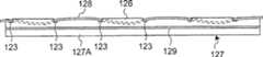
图12A及12B是示意性地表示作为该发明的光电复合传送装置的第十二实施例的光电复合缆线的平面图及截面图。图12C表示所述光电复合线缆穿过直径3mm以下的孔时的形状。12A and 12B are plan views and cross-sectional views schematically showing a photoelectric composite cable as a twelfth embodiment of the photoelectric composite transmission device of the present invention. FIG. 12C shows the shape of the photoelectric composite cable when it passes through a hole with a diameter of 3 mm or less.
该第十二实施例包括作为具有光波导129的光信号传输部件的波导基板127和作为电信号传输部件的电线128。所述波导基板127在基部127A的单侧隔开规定的间隔形成多个缺口部123。而且,所述电线128以交替跨越基部127A在相邻的所述缺口部123和123之间的部分126的一侧和另一侧的方式、嵌入所述多个缺口部123。并且,所述光波导基板127由例如聚酰亚胺等树脂制成。This twelfth embodiment includes a
另外,在该实施例中,虽然仅在所述光波导基板127的基部127A的单侧形成所述缺口部123,但是也可以在基部127A的两侧交替形成缺口部。此时,可以选择所述两侧的缺口部中的一侧作为嵌入所述电线128的缺口部。而且,也可以在所述光波导基板127上螺旋状地缠绕所述电线128而在所述两侧的缺口部中交替地嵌入电线128。并且,也可以在所述两侧的缺口部中分别嵌入不同的电线。In addition, in this embodiment, although the
另外,在所述第一~六实施例中,光信号传输部件为光纤。作为该光纤,可以列举POF(塑料光纤)、PCS(塑料包层石英光纤)、玻璃光纤、多芯光纤等。并且,通过将所述第一~十二实施例中的光电复合缆线如图1C等所示那样弯曲为两个、实际的直径在3mm以下时,能够作为适用于例如具有铰接部的折叠式手机的光电复合传送装置。In addition, in the first to sixth embodiments, the optical signal transmission component is an optical fiber. Examples of the optical fiber include POF (plastic optical fiber), PCS (plastic clad silica optical fiber), glass optical fiber, multi-core optical fiber, and the like. In addition, by bending the photoelectric composite cables in the first to twelfth embodiments into two as shown in FIG. Photoelectric composite transmission device for mobile phones.
以上对本发明的实施例进行了说明,但是其可以进行种种变化,这是显而易见的。这种变化并不脱离本发明的精神和范围。对本领域的技术人员而言不言自明的变化全部包含在本发明的内容中。Although the embodiments of the present invention have been described above, it is obvious that various changes can be made. Such changes do not depart from the spirit and scope of the invention. Changes that are self-evident to a person skilled in the art are all included in the content of the present invention.
Claims (21)
Applications Claiming Priority (2)
| Application Number | Priority Date | Filing Date | Title |
|---|---|---|---|
| JP020322/08 | 2008-01-31 | ||
| JP2008020322AJP4610624B2 (en) | 2008-01-31 | 2008-01-31 | Photoelectric composite transmission device and electronic device |
Publications (2)
| Publication Number | Publication Date |
|---|---|
| CN101499334Atrue CN101499334A (en) | 2009-08-05 |
| CN101499334B CN101499334B (en) | 2011-10-12 |
Family
ID=40931762
Family Applications (1)
| Application Number | Title | Priority Date | Filing Date |
|---|---|---|---|
| CN200910001648XAExpired - Fee RelatedCN101499334B (en) | 2008-01-31 | 2009-01-09 | Optical-electrical composite transmission device and electronic equipment |
Country Status (3)
| Country | Link |
|---|---|
| US (1) | US7835607B2 (en) |
| JP (1) | JP4610624B2 (en) |
| CN (1) | CN101499334B (en) |
Cited By (4)
| Publication number | Priority date | Publication date | Assignee | Title |
|---|---|---|---|---|
| CN102621645A (en)* | 2011-01-25 | 2012-08-01 | 乔伊·姆·特拉华公司 | Optical Cable Protection in Mining Systems |
| CN103427143A (en)* | 2012-05-21 | 2013-12-04 | 矢崎总业株式会社 | Waveguide and in-vehicle communication system |
| CN105144270A (en)* | 2013-02-01 | 2015-12-09 | 乐金显示有限公司 | Flexible display substrate, flexible organic light emitting display device and manufacturing method thereof |
| CN110291596A (en)* | 2017-12-27 | 2019-09-27 | 株式会社极诺玛 | For the scalable wiring tape of textile, wearable device and be furnished with route textile manufacturing method |
Families Citing this family (1)
| Publication number | Priority date | Publication date | Assignee | Title |
|---|---|---|---|---|
| JP6137931B2 (en)* | 2013-04-26 | 2017-05-31 | オリンパス株式会社 | Endoscope |
Family Cites Families (17)
| Publication number | Priority date | Publication date | Assignee | Title |
|---|---|---|---|---|
| JPS59112966U (en)* | 1983-01-20 | 1984-07-30 | 株式会社フジクラ | Fiber optic composite printed circuit |
| JPH0275604U (en)* | 1988-11-28 | 1990-06-11 | ||
| JPH06281831A (en)* | 1993-03-25 | 1994-10-07 | Nippon Telegr & Teleph Corp <Ntt> | Electric wiring/optical wiring combined flexible printed circuit board and substrate therefor |
| JP2000124695A (en)* | 1998-10-12 | 2000-04-28 | Canon Inc | Cable wiring structure |
| JP2000147270A (en)* | 1998-11-09 | 2000-05-26 | Nippon Telegr & Teleph Corp <Ntt> | Printed wiring board with optical wiring function |
| JP2001119460A (en) | 1999-10-20 | 2001-04-27 | Fujitsu Ltd | Foldable mobile phone and flexible cable |
| JP2002237226A (en) | 2001-02-07 | 2002-08-23 | Risutemu Kk | Composite cable and connector |
| JP4102675B2 (en)* | 2003-01-30 | 2008-06-18 | オプトレックス株式会社 | Flexible wiring board and liquid crystal display device |
| JP2004350155A (en)* | 2003-05-23 | 2004-12-09 | Sony Corp | Optical communication system, optical communication device, and optical cable |
| JP2005099642A (en)* | 2003-09-26 | 2005-04-14 | Fujikura Ltd | Optical fiber sheet manufacturing method |
| US7211784B2 (en) | 2004-03-16 | 2007-05-01 | Kabushiki Kaisha Toshiba | Photo-detection device and temperature distribution detection device using the same |
| US7373034B2 (en)* | 2004-09-02 | 2008-05-13 | Nec Corporation | Optoelectronic hybrid integrated module |
| JP2006091241A (en)* | 2004-09-22 | 2006-04-06 | Hitachi Cable Ltd | Opto-electric composite wiring component and electronic device using the same |
| JP4434898B2 (en)* | 2004-09-27 | 2010-03-17 | 株式会社フジクラ | Flexible printed circuit board installation structure |
| JP2007140369A (en)* | 2005-11-22 | 2007-06-07 | Fujikura Ltd | Optical composite printed circuit board |
| JP4322276B2 (en) | 2006-03-02 | 2009-08-26 | シャープ株式会社 | Mobile phones and electronic devices |
| US7920764B2 (en)* | 2007-05-04 | 2011-04-05 | Anthony Stephen Kewitsch | Electrically traceable and identifiable fiber optic cables and connectors |
- 2008
- 2008-01-31JPJP2008020322Apatent/JP4610624B2/ennot_activeExpired - Fee Related
- 2009
- 2009-01-07USUS12/349,635patent/US7835607B2/ennot_activeExpired - Fee Related
- 2009-01-09CNCN200910001648XApatent/CN101499334B/ennot_activeExpired - Fee Related
Cited By (10)
| Publication number | Priority date | Publication date | Assignee | Title |
|---|---|---|---|---|
| CN102621645A (en)* | 2011-01-25 | 2012-08-01 | 乔伊·姆·特拉华公司 | Optical Cable Protection in Mining Systems |
| CN102621645B (en)* | 2011-01-25 | 2015-08-12 | 乔伊·姆·特拉华公司 | Optical Cable Protection in Mining Systems |
| CN105158861B (en)* | 2011-01-25 | 2019-03-08 | 久益环球地下采矿有限责任公司 | Cable protection in mining system |
| CN103427143A (en)* | 2012-05-21 | 2013-12-04 | 矢崎总业株式会社 | Waveguide and in-vehicle communication system |
| US9130253B2 (en) | 2012-05-21 | 2015-09-08 | Yazaki Corporation | Waveguide for in-vehicle communication system |
| CN103427143B (en)* | 2012-05-21 | 2016-03-23 | 矢崎总业株式会社 | Waveguide and Che Nei communication system |
| CN105144270A (en)* | 2013-02-01 | 2015-12-09 | 乐金显示有限公司 | Flexible display substrate, flexible organic light emitting display device and manufacturing method thereof |
| CN105144270B (en)* | 2013-02-01 | 2018-11-02 | 乐金显示有限公司 | Flexible display substrate, flexible organic light emitting display device and manufacturing method thereof |
| CN110291596A (en)* | 2017-12-27 | 2019-09-27 | 株式会社极诺玛 | For the scalable wiring tape of textile, wearable device and be furnished with route textile manufacturing method |
| CN110291596B (en)* | 2017-12-27 | 2022-02-22 | 株式会社极诺玛 | Stretchable wiring tape for textile, wearable device and method for manufacturing textile with wiring |
Also Published As
| Publication number | Publication date |
|---|---|
| JP2009180960A (en) | 2009-08-13 |
| US7835607B2 (en) | 2010-11-16 |
| JP4610624B2 (en) | 2011-01-12 |
| US20090196545A1 (en) | 2009-08-06 |
| CN101499334B (en) | 2011-10-12 |
Similar Documents
| Publication | Publication Date | Title |
|---|---|---|
| CN101060549B (en) | Mobile phones and electronic equipment | |
| US8204351B2 (en) | Optical module | |
| JP4096988B1 (en) | Photoelectric composite wiring module and information processing apparatus | |
| US9798089B2 (en) | Fiber optic connector assemblies having windowed optical fibers and methods thereof | |
| EP2405291A2 (en) | Method and apparatus for routing optical fibers in flexible circuits | |
| JP2007293315A (en) | Opto-electric composite wiring board and its coupling efficiency evaluation method | |
| CN102654607A (en) | Photoelectric transmission module | |
| CN101449190A (en) | Fiber optic cable and fiber optic cable assembly for wireless access | |
| CN101499334A (en) | Optical-electrical composite transmission device and electronic equipment | |
| US9048651B2 (en) | Low-profile strain relief and cable retention | |
| CN106257774A (en) | Distribution component | |
| CN104035167A (en) | Connector cable and method for manufacturing connectored cable | |
| US20190000307A1 (en) | Optical transmitter and endoscope | |
| CN102645712A (en) | Flexible Flat Optical Cable | |
| EP2211217A1 (en) | Printed circuit board fiberoptical transceiver in surface mount technology (SMT) | |
| JP5445026B2 (en) | Electric light composite harness | |
| JP2013020158A (en) | Optical/electric composite cable with electric connector | |
| JP5515377B2 (en) | Composite harness and manufacturing method thereof | |
| JP5879810B2 (en) | Optical module and cable with optical module | |
| CN102326212B (en) | Composite harness and method for producing same | |
| CN114207496A (en) | Photoelectric composite transmission module | |
| EP1244177B1 (en) | Electrical device and method for connecting a cable to the same | |
| TWI490886B (en) | Composite harness and method for manufacturing the same | |
| KR20110009522U (en) | Small-diameter coaxial cable harness | |
| JP2007256326A (en) | Connection fixing part structure of optical cable composite cable |
Legal Events
| Date | Code | Title | Description |
|---|---|---|---|
| C06 | Publication | ||
| PB01 | Publication | ||
| C10 | Entry into substantive examination | ||
| SE01 | Entry into force of request for substantive examination | ||
| C14 | Grant of patent or utility model | ||
| GR01 | Patent grant | ||
| CF01 | Termination of patent right due to non-payment of annual fee | ||
| CF01 | Termination of patent right due to non-payment of annual fee | Granted publication date:20111012 Termination date:20160109 |