CN101495047B - Vascular wound closure device and method - Google Patents
Vascular wound closure device and methodDownload PDFInfo
- Publication number
- CN101495047B CN101495047BCN2006800372741ACN200680037274ACN101495047BCN 101495047 BCN101495047 BCN 101495047BCN 2006800372741 ACN2006800372741 ACN 2006800372741ACN 200680037274 ACN200680037274 ACN 200680037274ACN 101495047 BCN101495047 BCN 101495047B
- Authority
- CN
- China
- Prior art keywords
- catheter
- closure device
- wound
- wound closure
- closure
- Prior art date
- Legal status (The legal status is an assumption and is not a legal conclusion. Google has not performed a legal analysis and makes no representation as to the accuracy of the status listed.)
- Expired - Fee Related
Links
Images


Classifications
- A—HUMAN NECESSITIES
- A61—MEDICAL OR VETERINARY SCIENCE; HYGIENE
- A61B—DIAGNOSIS; SURGERY; IDENTIFICATION
- A61B17/00—Surgical instruments, devices or methods
- A61B17/0057—Implements for plugging an opening in the wall of a hollow or tubular organ, e.g. for sealing a vessel puncture or closing a cardiac septal defect
- A—HUMAN NECESSITIES
- A61—MEDICAL OR VETERINARY SCIENCE; HYGIENE
- A61B—DIAGNOSIS; SURGERY; IDENTIFICATION
- A61B17/00—Surgical instruments, devices or methods
- A61B17/02—Surgical instruments, devices or methods for holding wounds open, e.g. retractors; Tractors
- A61B17/0206—Surgical instruments, devices or methods for holding wounds open, e.g. retractors; Tractors with antagonistic arms as supports for retractor elements
- A—HUMAN NECESSITIES
- A61—MEDICAL OR VETERINARY SCIENCE; HYGIENE
- A61M—DEVICES FOR INTRODUCING MEDIA INTO, OR ONTO, THE BODY; DEVICES FOR TRANSDUCING BODY MEDIA OR FOR TAKING MEDIA FROM THE BODY; DEVICES FOR PRODUCING OR ENDING SLEEP OR STUPOR
- A61M25/00—Catheters; Hollow probes
- A61M25/01—Introducing, guiding, advancing, emplacing or holding catheters
- A61M25/06—Body-piercing guide needles or the like
- A61M25/0662—Guide tubes
- A61M25/0668—Guide tubes splittable, tear apart
- A—HUMAN NECESSITIES
- A61—MEDICAL OR VETERINARY SCIENCE; HYGIENE
- A61B—DIAGNOSIS; SURGERY; IDENTIFICATION
- A61B17/00—Surgical instruments, devices or methods
- A61B17/00491—Surgical glue applicators
- A—HUMAN NECESSITIES
- A61—MEDICAL OR VETERINARY SCIENCE; HYGIENE
- A61B—DIAGNOSIS; SURGERY; IDENTIFICATION
- A61B17/00—Surgical instruments, devices or methods
- A61B17/34—Trocars; Puncturing needles
- A61B17/3417—Details of tips or shafts, e.g. grooves, expandable, bendable; Multiple coaxial sliding cannulas, e.g. for dilating
- A61B17/3421—Cannulas
- A61B17/3439—Cannulas with means for changing the inner diameter of the cannula, e.g. expandable
- A—HUMAN NECESSITIES
- A61—MEDICAL OR VETERINARY SCIENCE; HYGIENE
- A61B—DIAGNOSIS; SURGERY; IDENTIFICATION
- A61B17/00—Surgical instruments, devices or methods
- A61B17/00234—Surgical instruments, devices or methods for minimally invasive surgery
- A61B2017/00238—Type of minimally invasive operation
- A61B2017/00243—Type of minimally invasive operation cardiac
- A—HUMAN NECESSITIES
- A61—MEDICAL OR VETERINARY SCIENCE; HYGIENE
- A61B—DIAGNOSIS; SURGERY; IDENTIFICATION
- A61B17/00—Surgical instruments, devices or methods
- A61B17/00234—Surgical instruments, devices or methods for minimally invasive surgery
- A61B2017/00292—Surgical instruments, devices or methods for minimally invasive surgery mounted on or guided by flexible, e.g. catheter-like, means
- A—HUMAN NECESSITIES
- A61—MEDICAL OR VETERINARY SCIENCE; HYGIENE
- A61B—DIAGNOSIS; SURGERY; IDENTIFICATION
- A61B17/00—Surgical instruments, devices or methods
- A61B17/0057—Implements for plugging an opening in the wall of a hollow or tubular organ, e.g. for sealing a vessel puncture or closing a cardiac septal defect
- A61B2017/00637—Implements for plugging an opening in the wall of a hollow or tubular organ, e.g. for sealing a vessel puncture or closing a cardiac septal defect for sealing trocar wounds through abdominal wall
- A—HUMAN NECESSITIES
- A61—MEDICAL OR VETERINARY SCIENCE; HYGIENE
- A61B—DIAGNOSIS; SURGERY; IDENTIFICATION
- A61B17/00—Surgical instruments, devices or methods
- A61B17/0057—Implements for plugging an opening in the wall of a hollow or tubular organ, e.g. for sealing a vessel puncture or closing a cardiac septal defect
- A61B2017/00646—Type of implements
- A61B2017/0065—Type of implements the implement being an adhesive
- A—HUMAN NECESSITIES
- A61—MEDICAL OR VETERINARY SCIENCE; HYGIENE
- A61B—DIAGNOSIS; SURGERY; IDENTIFICATION
- A61B17/00—Surgical instruments, devices or methods
- A61B17/0057—Implements for plugging an opening in the wall of a hollow or tubular organ, e.g. for sealing a vessel puncture or closing a cardiac septal defect
- A61B2017/00646—Type of implements
- A61B2017/00654—Type of implements entirely comprised between the two sides of the opening
- A—HUMAN NECESSITIES
- A61—MEDICAL OR VETERINARY SCIENCE; HYGIENE
- A61B—DIAGNOSIS; SURGERY; IDENTIFICATION
- A61B17/00—Surgical instruments, devices or methods
- A61B17/0057—Implements for plugging an opening in the wall of a hollow or tubular organ, e.g. for sealing a vessel puncture or closing a cardiac septal defect
- A61B2017/00646—Type of implements
- A61B2017/00659—Type of implements located only on one side of the opening
- A—HUMAN NECESSITIES
- A61—MEDICAL OR VETERINARY SCIENCE; HYGIENE
- A61B—DIAGNOSIS; SURGERY; IDENTIFICATION
- A61B17/00—Surgical instruments, devices or methods
- A61B17/0057—Implements for plugging an opening in the wall of a hollow or tubular organ, e.g. for sealing a vessel puncture or closing a cardiac septal defect
- A61B2017/00672—Locating means therefor, e.g. bleed back lumen
- A—HUMAN NECESSITIES
- A61—MEDICAL OR VETERINARY SCIENCE; HYGIENE
- A61B—DIAGNOSIS; SURGERY; IDENTIFICATION
- A61B17/00—Surgical instruments, devices or methods
- A61B2017/00831—Material properties
- A61B2017/00862—Material properties elastic or resilient
- A—HUMAN NECESSITIES
- A61—MEDICAL OR VETERINARY SCIENCE; HYGIENE
- A61B—DIAGNOSIS; SURGERY; IDENTIFICATION
- A61B17/00—Surgical instruments, devices or methods
- A61B2017/00831—Material properties
- A61B2017/00884—Material properties enhancing wound closure
- A—HUMAN NECESSITIES
- A61—MEDICAL OR VETERINARY SCIENCE; HYGIENE
- A61B—DIAGNOSIS; SURGERY; IDENTIFICATION
- A61B17/00—Surgical instruments, devices or methods
- A61B2017/00831—Material properties
- A61B2017/00942—Material properties hydrophilic
- A—HUMAN NECESSITIES
- A61—MEDICAL OR VETERINARY SCIENCE; HYGIENE
- A61B—DIAGNOSIS; SURGERY; IDENTIFICATION
- A61B90/00—Instruments, implements or accessories specially adapted for surgery or diagnosis and not covered by any of the groups A61B1/00 - A61B50/00, e.g. for luxation treatment or for protecting wound edges
- A61B90/03—Automatic limiting or abutting means, e.g. for safety
- A61B2090/037—Automatic limiting or abutting means, e.g. for safety with a frangible part, e.g. by reduced diameter
- A—HUMAN NECESSITIES
- A61—MEDICAL OR VETERINARY SCIENCE; HYGIENE
- A61M—DEVICES FOR INTRODUCING MEDIA INTO, OR ONTO, THE BODY; DEVICES FOR TRANSDUCING BODY MEDIA OR FOR TAKING MEDIA FROM THE BODY; DEVICES FOR PRODUCING OR ENDING SLEEP OR STUPOR
- A61M25/00—Catheters; Hollow probes
- A61M25/01—Introducing, guiding, advancing, emplacing or holding catheters
- A61M25/06—Body-piercing guide needles or the like
- A61M25/0662—Guide tubes
- A61M2025/0681—Systems with catheter and outer tubing, e.g. sheath, sleeve or guide tube
Landscapes
- Health & Medical Sciences (AREA)
- Life Sciences & Earth Sciences (AREA)
- Surgery (AREA)
- General Health & Medical Sciences (AREA)
- Public Health (AREA)
- Engineering & Computer Science (AREA)
- Biomedical Technology (AREA)
- Heart & Thoracic Surgery (AREA)
- Veterinary Medicine (AREA)
- Animal Behavior & Ethology (AREA)
- Medical Informatics (AREA)
- Nuclear Medicine, Radiotherapy & Molecular Imaging (AREA)
- Molecular Biology (AREA)
- Cardiology (AREA)
- Pulmonology (AREA)
- Hematology (AREA)
- Biophysics (AREA)
- Anesthesiology (AREA)
- Surgical Instruments (AREA)
- Materials For Medical Uses (AREA)
Abstract
Description
Translated fromChinese相关申请related application
本申请要求2005年10月5日提交的美国临时专利申请序列号60/723,723的优先权,其全部内容在此引入作为参考。This application claims priority to US Provisional Patent Application Serial No. 60/723,723, filed October 5, 2005, the entire contents of which are hereby incorporated by reference.
发明背景Background of the invention
发明领域field of invention
本发明大体上涉及促进血管开口封闭的系统。更具体地,本发明在血管附近输送材料。The present invention generally relates to systems for promoting closure of blood vessel openings. More specifically, the present invention delivers materials near blood vessels.
相关领域的说明Description of related fields
在许多医疗操作中,必须在组织上开口以便对该开口进行某种形式的治疗、诊断或修复。例如,为了进行腔内球囊血管成形术,在动脉上制造开口以便插入导管以在血管中输送球囊。之后必须封闭这个开口。In many medical procedures, an opening must be made in tissue in order to perform some form of treatment, diagnosis or repair of the opening. For example, for intraluminal balloon angioplasty, an opening is made in an artery for insertion of a catheter to deliver a balloon within the vessel. This opening must then be closed.
腔内球囊血管成形术被用于治疗外周血管疾病以增加或恢复肢体中显著变窄的动脉中的血流;它也被用于治疗冠状动脉阻塞。实际上,冠状血管成形术已作为分流手术主要可行的替代方法,用于狭窄和阻塞的冠状动脉的血管再通。与分流手术不同,血管成形术不需要全身麻醉、打开胸壁、使用心肺机或输血。血管成形术不仅对患者的侵入较少并造成较小的创伤,而且由于住院时间较短和恢复时间较短而花费较少。Endoluminal balloon angioplasty is used to treat peripheral vascular disease to increase or restore blood flow in significantly narrowed arteries in extremities; it is also used to treat blocked coronary arteries. Indeed, coronary angioplasty has emerged as the main viable alternative to bypass surgery for the recanalization of narrowed and blocked coronary arteries. Unlike bypass surgery, angioplasty does not require general anesthesia, opening of the chest wall, use of a heart-lung machine, or blood transfusion. Not only is angioplasty less invasive and less traumatic to the patient, it is also less expensive due to a shorter hospital stay and shorter recovery time.
进行腔内球囊血管成形术时,首先将空心针通过皮肤和周围的组织插入患者的股动脉。导线通过空心针前进并进入动脉,然后沿着患者的血管系统向待治疗的堵塞血管或瓣膜位置前进。放射摄影成像被用于帮助引导血管系统中的导线并进入待治疗的狭窄附近的位置。然后将球囊导管在导线上穿过并前进直到瘪球囊位于狭窄内。然后将该球囊反复充气以加宽变窄的血管。操作完成后,将导管和导线从血管和患者中取出。In intraluminal balloon angioplasty, a hollow needle is first inserted through the skin and surrounding tissue into the patient's femoral artery. The guidewire is advanced through the hollow needle and into the artery, and then advanced along the patient's vasculature to the location of the blocked vessel or valve to be treated. Radiographic imaging is used to help guide wires in the vasculature and into locations near the stenosis to be treated. The balloon catheter is then passed over the wire and advanced until the deflated balloon is within the stenosis. The balloon is then repeatedly inflated to widen the narrowed blood vessel. After the procedure is complete, the catheter and leads are removed from the vessel and the patient.
在取出血管成形术期间使用的导管之后,股动脉中的穿刺伤口必须封闭并且必须停止动脉中穿刺位置的出血。通常,在伤口周围区域施用冰块和/或压力持续高达数小时的时间以使出血停止。尽管如此,当患者移动时仍存在伤口再次开口并再次开始出血的可能性。另一可能的并发症是发展成假性动脉瘤,这增加感染和再开口的风险。After removal of the catheter used during angioplasty, the puncture wound in the femoral artery must be closed and bleeding from the puncture site in the artery must be stopped. Typically, ice and/or pressure is applied to the area around the wound for up to several hours to stop the bleeding. Still, there is a chance that the wound will open again and start bleeding again when the patient moves. Another possible complication is the development of a pseudoaneurysm, which increases the risk of infection and re-opening.
已经试图使用钉、夹子、胶原堵塞物和缝合线封闭穿刺伤口。这些努力及其附带的装置往往不方便又复杂并有引起危险并发症的明显可能性。例如,如果外来物质,如胶原侵入血管,将会促使血液凝结,导致不希望有的后果。Attempts have been made to close puncture wounds using staples, clips, collagen plugs and sutures. These efforts and the devices that accompany them are often inconvenient and complicated and have a distinct potential for dangerous complications. For example, if a foreign substance, such as collagen, invades a blood vessel, it will promote blood clotting, with undesired consequences.
多种其它的治疗和诊断操作包括导管通过血管前进。这样的操作使得封闭血管入口成为必要。此外,患者脉管系统的其它伤口也可能难以定位、接近和封闭。因此,帮助定位并封闭患者脉管系统中这样的伤口的装置和方法将会有益。具有一贯可靠的定位、分离并封闭穿刺伤口能力的装置将会消除目前与这样的伤口相关的长时间出血。Various other therapeutic and diagnostic procedures involve the advancement of catheters through blood vessels. Such manipulations necessitate the sealing of the vessel access. In addition, other wounds to the patient's vasculature may also be difficult to locate, access, and seal. Accordingly, devices and methods that assist in locating and sealing such wounds in a patient's vasculature would be beneficial. A device with the consistently reliable ability to locate, separate and seal puncture wounds would eliminate the prolonged bleeding currently associated with such wounds.
发明概述Summary of the invention
因此,本领域亟需用于精确定位血管伤口并封闭所述伤口的装置和方法。Accordingly, there is a great need in the art for devices and methods for precisely locating and sealing vascular wounds.
根据本发明的一实施方案,本发明提供血管伤口封闭装置。该装置包括具有一定尺寸并且设置为部分延伸穿过血管穿刺口的伸长导向件;和周向位于所述伸长导向件的多层封闭部分。该封闭部分可在导管上向远端移动。封闭部分的第一元件设置为咬合血管壁,并且其外径大于血管穿刺口的直径。封闭部分的第二元件包含止血材料。至少部分第一元件布置在第二元件的远端。第一元件咬合伸长导向件的外表面,以防止所述第二元件的止血材料在所述第一元件和所述导向件之间向远端移动。According to one embodiment of the present invention, the present invention provides a vascular wound closure device. The device includes an elongate guide sized and configured to extend partially through the access port of a blood vessel; and a multi-layer closure portion located circumferentially on the elongate guide. The closure portion is movable distally on the catheter. The first element of the sealing portion is configured to bite into the wall of the blood vessel and has an outer diameter larger than the diameter of the puncture port of the blood vessel. The second element of the closure portion comprises a hemostatic material. At least part of the first element is disposed distal to the second element. The first element engages the outer surface of the elongate guide to prevent distal migration of the hemostatic material of the second element between the first element and the guide.
在另一实施方案中,所述装置还包括适于在伸长导向件上向远端推动所述封闭部分的推进元件。在另一实施方案中,第一元件可独立于第二元件进行移动。在另一实施方案中,第二元件与第一元件附着。在另一实施方案中,导向件包括导管。另一实施方案还包括位于第一元件远端的导管周围的牵引件。在另一实施方案中,导向件包括导线。In another embodiment, the device further comprises an advancing element adapted to urge said closure portion distally over the elongate guide. In another embodiment, the first element is movable independently of the second element. In another embodiment, the second element is attached to the first element. In another embodiment, the guide comprises a catheter. Another embodiment also includes a puller positioned around the catheter at the distal end of the first member. In another embodiment, the guide includes a wire.
在另一实施方案中,推进元件布置在导向件周围,并且推进元件适于咬合第一元件,以便在推进元件的远端表面和第一元件的近端表面之间限定空间。In another embodiment, a pusher element is disposed about the guide, and the pusher element is adapted to engage the first element so as to define a space between a distal surface of the pusher element and a proximal surface of the first element.
在另一实施方案中,第一元件包括适于可滑动地容纳导向件的孔。导向件从中移去时孔通常趋于封闭。In another embodiment, the first member includes an aperture adapted to slidably receive the guide. The holes generally tend to close when the guide is removed therefrom.
另一实施方案还包括输送腔。第一元件和第二元件至少部分位于输送腔内。在另一实施方案中,第一元件包含止血材料。在另一实施方案中,第一元件通常是挠性的。但是在另一实施方案中,第一元件通常是刚性的。在一实施方案中,第一元件包含弹性元件,而在另一实施方案中,第一元件包含网。在某些实施方案中,第一元件是亲水的。另一实施方案包括包含壳聚糖的第一元件。在另一实施方案中,第二元件包含纤维壳聚糖毛绒。在另一实施方案中,第一元件的密度大于第二元件。Another embodiment also includes a delivery lumen. The first element and the second element are located at least partially within the delivery lumen. In another embodiment, the first element comprises a hemostatic material. In another embodiment, the first element is generally flexible. In another embodiment, however, the first element is generally rigid. In one embodiment, the first element comprises an elastic element, while in another embodiment, the first element comprises a mesh. In certain embodiments, the first element is hydrophilic. Another embodiment includes the first element comprising chitosan. In another embodiment, the second element comprises fibrous chitosan plush. In another embodiment, the density of the first element is greater than that of the second element.
根据另一实施方案,本发明提供医疗方法。该方法包括穿刺血管;通过穿刺伤口插入一种或多种治疗仪器并插入血管;通过一种或多种治疗仪器进行治疗手术操作;将封闭导管至少部分地插入穿刺伤口;在封闭导管外表面周围提供封闭元件。所述封闭元件的外径大于穿刺伤口。该方法还包括在封闭导管的外表面上推进封闭元件并与血管外壁咬合;以及在封闭导管上推进促进止血的材料。According to another embodiment, the present invention provides a method of medical treatment. The method includes puncturing a blood vessel; inserting one or more therapeutic instruments through the puncture wound and inserting the blood vessel; performing a therapeutic surgical procedure through the one or more therapeutic instruments; at least partially inserting a closure catheter into the puncture wound; surrounding the outer surface of the closure catheter Provide closure elements. The outer diameter of the closure element is larger than the puncture wound. The method also includes advancing a closure member over an outer surface of the closure catheter and engaging the outer wall of the blood vessel; and advancing a hemostasis-promoting material over the closure catheter.
根据一实施方案,治疗手术操作通过包括腔内球囊血管成形术操作的一种或多种治疗仪器进行。According to one embodiment, the therapeutic surgical procedure is performed by one or more therapeutic instruments including an endoluminal balloon angioplasty procedure.
在另一实施方案中,封闭元件的结构刚性大于止血材料。在另一实施方案中,封闭导管的外径大于通过穿刺口插入的一种或多种治疗仪器的最大直径。在另一实施方案中,封闭元件的外径大于封闭导管的外径。In another embodiment, the closure element is structurally more rigid than the hemostatic material. In another embodiment, the outer diameter of the closure catheter is greater than the largest diameter of one or more therapeutic instruments inserted through the puncture port. In another embodiment, the outer diameter of the closure element is greater than the outer diameter of the closure conduit.
为了概述优选实施方案和达到的与现有技术相比的优点,上文已经描述了某些实施方案和优点。当然,应当理解,任何具体的实施方案无需达到所有这样的优点。因此,例如本领域技术人员将意识到,本发明可以以实现或优化本文教导的一个优点或一组优点的方式来体现或实施,而不必要实现可能本文教导或建议的其它目的或优点。Certain embodiments and advantages have been described above in order to outline the preferred embodiments and the advantages achieved over the prior art. Of course, it should be understood that not all such advantages need be achieved by any particular implementation. Thus, for example, those skilled in the art will appreciate that the present invention may be embodied or carried out in a manner that achieves or optimizes one advantage or group of advantages taught herein without necessarily achieving other objectives or advantages that may be taught or suggested herein.
从如下参考附图的优选实施方案的详细描述,以上讨论的实施方案和其它实施方案对于本领域技术人员将会更加明显,本发明不限于公开的任何具体的优选实施方案。The embodiments discussed above, and other embodiments, will become more apparent to those skilled in the art from the following detailed description of preferred embodiments with reference to the accompanying drawings, and the invention is not limited to any particular preferred embodiment disclosed.
附图的简要说明Brief description of the drawings
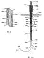
图1是显示组装待用的血管封闭装置的实施方案侧视图。Figure 1 is a side view of an embodiment showing a vessel sealing device assembled and ready for use.
图1A是用于图1装置的封闭元件的透视图。Figure 1A is a perspective view of a closure element for the device of Figure 1 .
图2是图1的装置远端部分的后视图。Figure 2 is a rear view of the distal portion of the device of Figure 1 .
图3是一实施方案的推进元件的侧视图。Figure 3 is a side view of a propulsion element of an embodiment.
图4示出图1的装置在导线上前进进入患者血管。FIG. 4 shows the device of FIG. 1 advanced over a guide wire into a patient's blood vessel.
图5示出图4中打开的牵引臂和正在使用的抽气工具的布置。Figure 5 shows the arrangement of the drawing arm in Figure 4 opened and the extraction tool in use.
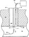
图6示出图5的布置,其中止血海绵已被推进与血管壁接触。Figure 6 shows the arrangement of Figure 5 with the hemostatic sponge pushed into contact with the vessel wall.
图7示出图6中移去牵引臂的布置。Figure 7 shows the arrangement of Figure 6 with the trailing arm removed.
图8示出图7中移去导管和导线的布置。FIG. 8 shows the arrangement of FIG. 7 with the catheter and wire removed.
图9示出图8的布置,其中可流动的粘合剂正在向海绵输送。Figure 9 shows the arrangement of Figure 8 with flowable adhesive being delivered to the sponge.
图10示出图8的布置,其中推进元件正在从患者中移去。Figure 10 shows the arrangement of Figure 8 with the advancement element being removed from the patient.
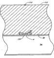
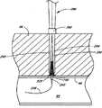
图11示出使用实施方案的装置和方法治疗后的封闭的穿刺伤口。Figure 11 shows a closed puncture wound after treatment using the devices and methods of the embodiments.
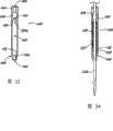
图12是血管伤口封闭装置的另一实施方案的侧视图。Figure 12 is a side view of another embodiment of a vascular wound closure device.
图13是图12的装置的横断面视图。FIG. 13 is a cross-sectional view of the device of FIG. 12 .
图14示出了分成两半的图12的装置的输送管部分。Figure 14 shows the delivery tube portion of the device of Figure 12 split in half.
图15示出了适于与图12的装置一起使用的导管部分的实施方案。FIG. 15 shows an embodiment of a catheter portion suitable for use with the device of FIG. 12 .
图16示出布置在输送管部分的两半之间的图15的导管部分。Figure 16 shows the catheter section of Figure 15 arranged between the two halves of the delivery tube section.
图17A是图12的部分装置的特写图。FIG. 17A is a close-up view of a portion of the device of FIG. 12 .
图17B是图12的另一部分装置的特写图。FIG. 17B is a close-up view of another portion of the device of FIG. 12 .
图18是沿图17A中线18-18的截面的特写图。Fig. 18 is a close-up view of a section taken along line 18-18 in Fig. 17A.
图19示出图12的装置的推进元件。FIG. 19 shows a propulsion element of the device of FIG. 12 .
图20是沿图13中线20-20的截面的特写图。FIG. 20 is a close-up view of a section taken along line 20-20 of FIG. 13. FIG.
图21是沿图13中线21-21截面的特写图。Fig. 21 is a close-up view of a section along line 21-21 in Fig. 13 .
图22是与图12的装置一起使用的套环部分的透视图。22 is a perspective view of a collar portion for use with the device of FIG. 12 .
图23示出了将图12装置的一部分推向组织伤口。Figure 23 shows pushing a portion of the device of Figure 12 towards a tissue wound.
图24示出了图12装置的一部分位于血管伤口附近的合适位置。Figure 24 shows a portion of the device of Figure 12 in place near a vascular wound.
图25示出了图24的装置位于伤口附近的合适位置并展开止血剂的布置。Figure 25 shows the arrangement of the device of Figure 24 in place about a wound and deploying a hemostat.
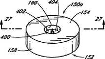
图26是封闭元件另一实施方案的透视图。Figure 26 is a perspective view of another embodiment of a closure element.
图27是沿图26中线27-27的横断面视图。FIG. 27 is a cross-sectional view taken along line 27-27 of FIG. 26. FIG.
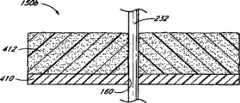
图28是具有导管从其中延伸的封闭元件的另一实施方案的剖视图。Figure 28 is a cross-sectional view of another embodiment of a closure member having a conduit extending therefrom.
图29示出了移去导管的图28的封闭元件。Figure 29 shows the closure element of Figure 28 with the catheter removed.
图30示出了封闭元件另一实施方案的剖视图,所述封闭元件适于与互补地形成的推进元件的远端可释放地咬合。Figure 30 shows a cross-sectional view of another embodiment of a closure element adapted to releasably engage with a complementary formed distal end of a pusher element.
图31示出了图30部分咬合并且止血材料位于封闭元件和推进元件之间的空间的布置。Figure 31 shows the arrangement of Figure 30 partially occluded with hemostatic material in the space between the closure element and the pusher element.
图32示出了图31的布置,其中封闭元件与推进元件咬合,使得空间不能进一步压缩。Figure 32 shows the arrangement of Figure 31 with the closure element engaged with the pusher element such that the space cannot be compressed further.
图33示出了一个实施方案中设置的牵引件的一牵引臂的侧面平面图。Figure 33 shows a side plan view of a puller arm of a puller provided in one embodiment.
图34示出了位于图33的牵引臂中的导管的实施方案。FIG. 34 shows an embodiment of the catheter positioned in the pull arm of FIG. 33 .
图35示出了部分血管封闭装置的另一实施方案。Figure 35 illustrates another embodiment of a partial vessel closure device.
图36示出了血管伤口封闭组件的另一实施方案。Figure 36 illustrates another embodiment of a vascular wound closure assembly.
图37示出了前进进入血管壁附近位置的图36的组件。Fig. 37 shows the assembly of Fig. 36 advanced into a position near a vessel wall.
图38是适于包含一实施方案的止血材料的囊的透视图。Figure 38 is a perspective view of a balloon suitable for containing an embodiment of a hemostatic material.
图39示出了布置在封闭元件近端的导管上的图38的囊。Fig. 39 shows the balloon of Fig. 38 disposed on the catheter proximal to the closure element.
图40示出了布置在导管上的图38的囊。Figure 40 shows the balloon of Figure 38 deployed on a catheter.
优选实施方案的详细描述Detailed description of the preferred embodiment
这些实施方案对于封闭难以接近和/或看得到的血管穿刺伤口尤其有用。难以直接并精确地修正伤口以封闭这样的伤口。另外,存在与直接修正血管相关的缺陷。例如,由于临床医生无法看到伤口,难以正确放置封闭介质如缝合线、钉或夹子。不正确地放置这样的封闭介质很可能引起不完全的封闭;穿刺伤口仍然开着,而临床医生可能还不知道。另外,不正确地放置封闭介质可能引起血管的永久损伤,包括撕开和额外的穿刺伤口。此外,如果封闭介质通过伤口延伸进入血流中,该介质能够增加形成血栓的可能性或可能将潜在的毒性物质引入血流中。当然,封闭介质不小心释放入血流中可能导致严重的血管堵塞并发症。These embodiments are particularly useful for sealing vascular puncture wounds that are difficult to access and/or are visible. It is difficult to directly and precisely correct wounds to close such wounds. Additionally, there are drawbacks associated with directly correcting blood vessels. For example, due to the clinician's inability to see the wound, it is difficult to properly place sealing media such as sutures, staples or clips. Improper placement of such a sealing medium is likely to cause incomplete closure; the puncture wound remains open, and the clinician may not be aware of it. Additionally, improper placement of the sealing medium may cause permanent damage to the vessel, including tearing and additional puncture wounds. Furthermore, if the occlusive medium extends through the wound into the bloodstream, the medium can increase the likelihood of thrombus formation or possibly introduce potentially toxic substances into the bloodstream. Of course, inadvertent release of the occlusive medium into the bloodstream can lead to serious vascular occlusive complications.
参考图1,血管伤口封闭组件30的一实施方案包括具有远端34和近端36的伸长导管32。穿过导管32的远端34形成远端开口38并沿导管32的纵轴开口。导管32优选在远端34包括锥形尖端40。导管32的伸长主体42位于锥形尖端40的近端。主体42优选沿其长度具有基本一致的直径。内腔44在导管32内从远端开口38纵向延伸至近端36。Referring to FIG. 1 , one embodiment of a vascular
在该例证的实施方案中,在导管32的近端36具有连接件部分46。连接件部分46包括主内腔48和次内腔50。主内腔48沿导管32的纵轴延伸并与导管内腔44一同延伸。次内腔50从主内腔48向外延伸,但与主内腔48和导管内腔44相通。优选地,主内腔和次内腔48、50一般呈“Y”形。近端开口52位于主内腔48的近端,而且与远端开口38相像,沿纵轴开口。次开口54位于次内腔50的近端。In the illustrated embodiment, there is a
远端和近端开口38、52优选有一定尺寸并适于容纳导线58如用于血管成形术和其它血管操作中的导线。这样,导线58能够穿过导管32且导管32能够在导线58上前进。The distal and
在导管32的远端34附近,穿过导管32侧壁至少形成一个孔60。优选地,形成至少两个孔60。所有的孔60优选与导管32的远端34具有基本上相同的距离。At least one
继续参考图1,选择性地提供真空或其它抽气源64,并通过管66与导管连接件部分46的次内腔50相通。因此,能够通过导管内腔44抽真空。优选地,容纳导线58的远端和近端开口38、52有一定尺寸使得导线58基本上堵住开口;因此,主要通过孔60抽真空。在以下的实施方案中,在抽气源64和导管32之间装有观察口68。观察口68设置为用于允许临床医生观察通过孔60和通过导管内腔44抽气吸走的物质。观察口68将在下文更详细地讨论。With continued reference to FIG. 1 , a vacuum or other suction source 64 is optionally provided and communicates with the secondary lumen 50 of the
参考图1和2,在导管32上优选安装牵引件70。牵引件70包括在导管32上纵向排列的反向伸长牵引臂72。牵引件主体74设置为当临床医生操作时选择性地打开和关闭牵引臂72。牵引件70的伸长牵引臂72位于导管32上,使得臂的远端76与导管孔60的近端的距离至少与动脉壁的宽度相同,优选至少约0.5至2毫米。Referring to FIGS. 1 and 2 , a
应当理解,本发明的装置能够包括与图1和2示出的个别结构有某些不同的结构。例如,能够适当地使用其它的导管和牵引件结构。例如,某些可接受的导管和牵引件的实施方案参见1999年6月4日提交的美国申请序列号09/325,982,现在的美国专利第6,287,322号和2004年8月16日提交的美国申请序列号10/919,939,每一文献的全部内容在此引入作为参考。It should be understood that the apparatus of the present invention can include some different structures than the individual structures shown in FIGS. 1 and 2 . For example, other catheter and puller configurations can be suitably used. See, for example, U.S. Application Serial No. 09/325,982, filed June 4, 1999, now U.S. Patent No. 6,287,322, and U.S. Application Serial No. 16, 2004, for some acceptable catheter and puller embodiments. Serial No. 10/919,939, each of which is hereby incorporated by reference in its entirety.
再次具体参考图1,止血元件80布置在牵引件70近端的导管32上。如在下文将更详细地讨论的那样,止血元件包含由止血剂形成的材料或包括止血剂的材料。止血剂适于辅助血液凝结。在一实施方案中,止血元件80包含海绵或海绵样物质。在本说明书中,术语海绵规定为根据其通常意思使用的广义术语,并且非限制性地是这样的材料,其是至少部分多孔的并适于允许至少某些血液流入并在其中流动以便用血液浸透该材料。例如,海绵可以包括天然或人造海绵、纺织或非纺织织物、由通常随机排列的纤维制成的泡芙等。另外,海绵可以包含吸收与该材料接触的至少部分血液的材料,或可以包含不吸收血液的材料。Referring again specifically to FIG. 1 , hemostatic element 80 is disposed on
为了本说明书的需要,止血元件80指海绵80。然而,应当理解术语“海绵”的使用不应被用来限制可用作止血元件的材料的范围。实际上,显著辅助或促进血液凝结的任何材料都能够用作止血元件。For the purposes of this specification, the hemostatic element 80 is referred to as the sponge 80 . However, it should be understood that the use of the term "sponge" should not be used to limit the range of materials that can be used as the hemostatic element. Virtually any material that significantly assists or promotes blood clotting can be used as the hemostatic element.
在本说明书中,术语止血剂根据其通常的意思作为广义术语使用,并且非限制性地是显著促进血液凝结的试剂。这样的试剂可采取多种形式,包括液体、粉末、固体、珠等并能够包括基质或载体或与基质或载体结合。在本说明书中,术语止血材料也是以其通常意思中使用的广义术语。它非限制性地指具有显著促进血液凝结的性质的任何材料。因此,止血材料能够包括单独使用的止血剂或者与基质或载体结合的止血剂,所述基质或载体是与该止血剂分别形成的。术语止血材料包括止血海绵。In this specification, the term hemostatic agent is used according to its usual meaning as a broad term, and is an agent that significantly promotes blood coagulation without limitation. Such agents may take a variety of forms, including liquids, powders, solids, beads, etc. and can include or be associated with a matrix or carrier. In this specification, the term hemostatic material is also a broad term used in its usual meaning. It refers without limitation to any material that has properties that significantly promote blood clotting. Thus, the hemostatic material can include a hemostat used alone or in combination with a matrix or carrier that is formed separately from the hemostat. The term hemostatic material includes hemostatic sponges.
优选地,海绵80围绕导管主体42延伸,并布置海绵80使得它可在导管32上沿导管32纵向滑动。最优选地,导管32通过穿过海绵80的通道82延伸。通道82优选包含穿过海绵80形成的缝隙或其它孔。优选地,通道82处或附近的部分海绵80变形以容纳导管32。Preferably, the sponge 80 extends around the catheter body 42 and is arranged such that it can slide over the
具体参考图1和图1A,封闭元件150优选布置在海绵80远端的导管32上。在该例证的实施方案中,封闭元件150基本上环绕导管32且一般为环状(见图1A)。优选地,封闭元件150包含具有近端表面154、远端表面156、周界表面158和内孔160的一般为环状的主体152。优选地,内孔160的内径与导管32的外径基本上相同,使得环150和导管32之间的空间,如果有的话,非常小。With particular reference to FIGS. 1 and 1A , the
优选地,内孔160具有一定的尺寸和/或经处理使封闭元件150可在导管32的外表面滑动。在其它实施方案中,孔160的内径稍小于环状导管32的外径。这会确保封闭元件150和导管32之间更好地封闭,使得没有止血材料80可以在封闭元件150和导管32之间向远端挤出并进入穿刺伤口w。在另一实施方案中,润滑封闭元件内孔的表面以利于在导管32的外表面滑动,即使在导管32和封闭元件150之间的配合较紧时。Preferably,
推进元件84也布置在海绵80近端的导管32上。还参考图3,推进元件84包含主体部分86和近端柄部分88。穿过主体部分86形成伸长内腔90。如图1所示,内腔90优选环绕导管32以使推进元件84能相对导管32滑动。优选在靠近推进元件84远端处形成穿过主体部分86的多个孔92。A
如在下文将会联系图4更详细地讨论的那样,血管伤口封闭组件30使临床医生能够精确地定位皮下血管伤口“w”、接近伤口w并向伤口位置输送止血海绵80和封闭元件。止血海绵80包括在伤口w的位置处或附近帮助促使伤口w封闭的止血剂。As will be discussed in more detail below in connection with FIG. 4 , vascular
为了适当地施用止血海绵80,血管封闭组件30首先精确地定位并接近伤口w。应当理解,本发明的方法和装置能够用于封闭各种血管伤口和其它伤口。图1-11和附随的讨论,给出了用实施方案封闭患者股动脉94穿刺伤口的实施例。In order to properly apply the hemostatic sponge 80, the
具体参考图1、2、4和5,为了精确定位并接近股动脉伤口w,先将导管32在导线58上穿过,所述导线58已经预先通过穿刺伤口w插入患者的股动脉94。内腔44连到抽气源64上,组件30沿导线58上方穿过患者组织96以使导管32的远端尖端40延伸通过血管穿刺伤口w。Referring specifically to FIGS. 1 , 2 , 4 and 5 , in order to precisely locate and approach the femoral artery wound w, the
在推进组件30时,抽气源64通过孔60抽取体液。体液通过观察口68,这使得临床医生能够鉴别正在抽取的体液。观察口68能够具有任何合适的结构或位置。例如,观察口能够包含与导管连接的清澈的管、用作抽气源和观察口的基本透明的注射器、或基本透明的导管的一部分。最优选地,导管32用透明材料形成,以便临床医生在血液一通过导管开始被吸取时就知道。As the
如图4所示,当孔60穿过动脉壁98并进入血管94时,血液“b”开始通过孔60被吸入导管32并经过观察口68进行传输。因此,当在观察口68观察到血液b时,临床医生会知道孔60刚刚进入穿刺伤口w并且牵引臂72的远端76因而位于动脉94的外壁98处或附近,优选在动脉壁98的3mm以内,更优选在动脉壁98的2mm以内。然后如图5所示将牵引臂72分开,因而将周围组织96拉离伤口w并在穿刺伤口w周围形成区域100。分开牵引臂72还形成了通向伤口w的路径。导管32仍部分位于穿刺伤口w内,优选有效地堵住伤口并优选基本上防止血液流过伤口。优选地,孔60近端的导管32的部分使伤口w的边缘弯曲以增强导管32和穿刺伤口边缘的封闭。As shown in FIG. 4 , blood “b” begins to be drawn into
在另一实施方案中,孔60处或近端的部分导管32的直径大于导管32的其它部分。这样的直径较大的部分更有效地堵住伤口w。In another embodiment, the portion of
继续参考图5,在一实施方案中抽气工具102和/或冲洗工具能够用于清除掉可能在区域100内的体液及其它物质并清洁穿刺伤口w附近的血管94的壁98。在其它实施方案中,没有对区域100进行这样的清洗。Continuing to refer to FIG. 5 , in one embodiment an
参考接下来的图6,一旦精确地定位了穿刺伤口w,沿导管32向远端推进推进元件84,因而促使海绵80和封闭元件与血管壁98接触以围绕穿刺伤口w。如上所述并将在下文更详细地讨论的那样,海绵80包含帮助加速血液凝块在伤口位置w形成的止血剂,以帮助伤口更快愈合。在优选实施方案中,封闭元件也包含止血剂。Referring next to FIG. 6 , once the puncture wound w has been precisely positioned, the advancing
在该例证的实施方案中,推进元件84的远端仅与海绵80的部分近端直接接触。然而,优选地,海绵80有充足粘合力使得推进元件84的推进向远端整体推进海绵80。In the illustrated embodiment, the distal end of
在该例证的实施方案中,封闭元件150包含亲水止血材料,如纤维非纺织壳聚糖织物。尽管如海绵80的某些实施方案所述,优选的封闭元件由纤维材料制成,但在该实施方案中优选加工封闭元件150使其与海绵相比密度更大从而刚性更大。这样,封闭元件150结构牢固,足以承受通过推进元件84施加的压力而基本上不会变形到在封闭元件150与导管32之间和/或在封闭元件150与血管94之间形成缝隙的程度。这样,在使用期间,没有缝隙会使海绵80的纤维或其它部分通过封闭元件150并进入伤口w。另外,由于在该例证的实施方案中封闭元件刚性相对较大并优选外径大于伤口w的直径,封闭元件150本身不会通过伤口进入血管94。In the illustrated embodiment, the
尽管封闭元件150位于止血海绵80和穿刺伤口w之间,但是从穿刺口溢出的血液仍会流向止血海绵80,这将促进凝结以封闭伤口。Although the sealing
优选将海绵80安装在导管32上以基本上环绕导管32。因此,由于导管的尖端40在伤口中,且由于封闭元件150基本上立即环绕伤口w,海绵80基本上环绕封闭元件150,且优选部分海绵80位于血管壁98附近。The sponge 80 is preferably mounted on the
如图7所示,当海绵80在伤口w附近的适当位置时,能够移去牵引件70。当移去牵引件70时,围绕的身体组织96在海绵80、封闭元件和推进元件84周围萎陷。推进元件84保持海绵80和封闭元件的位置,而身体组织96围绕海绵80并开始血液凝结。As shown in FIG. 7, when the sponge 80 is in place about the wound w, the
参考接下来的图8,当推进元件84在适当的位置时,也能够从患者中移去导管32和导线58。曾被导管32占据的穿过海绵80的通道82优选向自身萎陷以便基本上封闭。导管32不再堵住血管伤口w,并预计来自血管94的血液b会流入并穿过封闭元件150并进一步进入海绵80,至少部分地浸透海绵80和封闭元件150。尽管在上述讨论的实施方案中牵引件70在导管32之前移去,应当理解,在另一实施方案中,导管可以在牵引件之前移去。Referring next to Fig. 8, the
在另一实施方案中,能够向推进元件84施加额外的压力以至少部分地阻止通过血管94的血流。以这种方式,临床医生可以控制血液多快地流过伤口w并进入海绵80。当然,能够使用其它的方法和装置暂时减少或停止通过血管的血流。In another embodiment, additional pressure can be applied to
如上所讨论的那样,海绵80优选包含由止血剂制成、在止血剂中浸泡或以其它方式用止血剂处理过的材料,所述止血剂尤其适于辅助血液凝结。因此,流进海绵的血液遇到该止血剂并会快速凝结,促使伤口通过血液凝结自然封闭。海绵样止血剂可获得并能够包括产品如Gelfoam


在一优选实施方案中,止血剂包含淀粉,如生物可吸收的微孔多糖微球(例如TRAUMADEXTM,由Waukesha,WI的Emergency MedicalProducts,Inc.销售,其使用Medafor,Inc.的HemadexTM多孔颗粒)。该微球具有微折转的多孔通路。该微球的孔尺寸促进水分吸收和血液的白蛋白、凝结因子和其它蛋白及细胞成分的超浓缩。该微球还影响血小板功能并提高纤维蛋白的成分。另外,据信该微球可以加速凝结酶反应速率。当用压力直接施加到活跃的出血伤口时,该颗粒充当分子筛从血液提取流体。该颗粒受控制的多孔性排斥血小板、红细胞和大于25,000道尔顿的血浆蛋白,然后将它们浓缩在该颗粒表面。这种分子排斥性质在颗粒表面形成了高浓度的血小板、凝血酶、纤维蛋白原和其它蛋白,产生了胶凝作用。胶凝的压紧的细胞和组分使正常的凝结级联加速。在该密集的蛋白-细胞基质内形成的纤维蛋白网紧紧地附着在周围的组织上。胶凝过程在数秒内启动,并且所产生的凝块虽然异常强韧但通常与微粒一同分解。这样的微孔多糖微球和其它的止血剂在申请人同时待审的题为“Deployable Multifunctional HemostaticAgent(可展开的多功能止血剂)”的申请中有更详细的讨论,所述申请于2004年6月14日提交,美国申请序列号为10/868,201,其全部内容在此引入作为参考。In a preferred embodiment, the hemostatic agent comprises starch, such as bioabsorbable microporous polysaccharide microspheres (e.g., TRAUMADEX™ , sold by Emergency Medical Products, Inc. of Waukesha, WI, which uses Hemadex™ porous particles from Medafor, Inc. ). The microsphere has micro-torque porous passages. The pore size of the microspheres facilitates water absorption and hyperconcentration of albumin, clotting factors and other protein and cellular components of the blood. The microspheres also affect platelet function and increase fibrin composition. Additionally, the microspheres are believed to accelerate the rate of the coagulation enzyme reaction. When applied directly to an actively bleeding wound with pressure, the particle acts as a molecular sieve to extract fluid from the blood. The particle's controlled porosity repels platelets, red blood cells, and plasma proteins greater than 25,000 Daltons, which then concentrate on the particle surface. This molecular repulsion property creates high concentrations of platelets, thrombin, fibrinogen, and other proteins on the particle surface, resulting in gelation. The gelled compacted cells and components accelerate the normal coagulation cascade. The fibrin mesh formed within this dense protein-cellular matrix tightly adheres to the surrounding tissue. The gelation process starts within seconds, and the resulting clot, although exceptionally strong, usually breaks down with the particles. Such microporous polysaccharide microspheres and other hemostatic agents are discussed in more detail in applicant's co-pending application entitled "Deployable Multifunctional HemostaticAgent", filed in 2004 U.S. Application Serial No. 10/868,201, filed June 14, the entire contents of which are hereby incorporated by reference.
任何适合的止血基质都可用作优选实施方案的止血剂的载体。然而,在特别优选的实施方案中,所述止血基质包括壳聚糖。壳聚糖得自甲壳质,而甲壳质为主要得自废弃的虾壳和蟹壳的生物聚合物。壳聚糖是甲壳质的主要衍生物,并且是脱乙酰化和解聚过程中各阶段的脱乙酰化甲壳质的集合名词。甲壳质和壳聚糖的化学结构类似于纤维素。区别在于,作为键接在纤维素中每一D-葡萄糖单元的C-2上的羟基基团的替代,甲壳质的每一D-葡萄糖单元的C-2上键接有乙酰化的氨基基团(-NHCOCH3),而在壳聚糖的每一D-葡萄糖单元的C-2上为氨基。Any suitable hemostatic substrate can be used as a carrier for the hemostatic agent of the preferred embodiment. However, in a particularly preferred embodiment, the hemostatic matrix comprises chitosan. Chitosan is obtained from chitin, a biopolymer obtained primarily from discarded shrimp and crab shells. Chitosan is the main derivative of chitin, and is a collective term for deacetylated chitin at various stages in the process of deacetylation and depolymerization. The chemical structure of chitin and chitosan is similar to cellulose. The difference is that instead of a hydroxyl group bonded to C-2 of each D-glucose unit in cellulose, chitin has an acetylated amino group bonded to C-2 of each D-glucose unit group (-NHCOCH3 ), and on the C-2 of each D-glucose unit of chitosan is an amino group.

甲壳质和壳聚糖都是无毒的,但与甲壳质相比,由于壳聚糖在酸溶液中具有更好的溶解性,因此在医疗和制药领域中应用更为广泛。壳聚糖显示出良好的生物相容性,并且可被脱乙酰壳多糖酶、木瓜蛋白酶、纤维素酶和酸蛋白酶生物降解。壳聚糖显示出抗炎和镇痛作用,并促进止血和伤口愈合。壳聚糖还在手术治疗和伤口保护中用作止血剂。美国专利第4,394,373号公开了壳聚糖的止血作用。Both chitin and chitosan are non-toxic, but compared with chitin, chitosan is more widely used in medical and pharmaceutical fields due to its better solubility in acid solutions. Chitosan shows good biocompatibility and is biodegradable by chitosanase, papain, cellulase and acid protease. Chitosan exhibits anti-inflammatory and analgesic effects, and promotes hemostasis and wound healing. Chitosan is also used as a hemostatic agent in surgical treatment and wound protection. US Patent No. 4,394,373 discloses the hemostatic effect of chitosan.
优选实施方案的装置中能够采用单一的止血基质或不同形式和/或组成的止血基质的组合。不同的基质形式都是优选的,例如纤维泡芙、毛绒形式、织物、片、缝合线、粉末等。能够采用不同基质形成材料的均匀混合物,或者能够从两种或更多种不同组成的基质制备复合基质。优选的复合物包括壳聚糖和胶原。关于壳聚糖和其它适合的基质的其它详细资料在申请人同时待审的申请“DeployableMultifunctional Hemostatic Agent(可展开的多功能止血剂)”中有更详细的讨论。A single hemostatic substrate or a combination of hemostatic substrates of different forms and/or compositions can be employed in the devices of the preferred embodiments. Different matrix forms are preferred, such as fiber puffs, plush forms, fabrics, sheets, sutures, powders, and the like. Homogenous mixtures of different matrix-forming materials can be employed, or composite matrices can be prepared from two or more matrices of different composition. A preferred complex includes chitosan and collagen. Additional details regarding chitosan and other suitable matrices are discussed in greater detail in applicant's co-pending application "Deployable Multifunctional Hemostatic Agent".
海绵样基质材料优选是柔软易折的并顺应血管、伤口及血管周围区域的结构。因此,海绵样材料尤其适合用于血管穿刺口周围的狭窄空间。另外,止血海绵80会由穿刺伤口w周围的组织96保持在适当的位置,当移去工具如牵引件70时所述组织96在海绵80上萎陷。The spongy matrix material is preferably soft and pliable and conforms to the structure of blood vessels, wounds and perivascular areas. Therefore, the sponge-like material is especially suitable for narrow spaces around vascular punctures. Additionally, the hemostatic sponge 80 will be held in place by the
如图9所示,为了进一步帮助保持海绵80和封闭元件150在适当的位置,来自粘合剂源108的易流动的粘合剂106能够通过推进元件84的内腔90输送到海绵80上。粘合剂106流过推进元件84开口的远端并还通过推进元件的主体部分86流过孔92。一旦固化,粘合剂106可在海绵80和封闭元件150周围及内部形成封闭层,从而将血液b限定在海绵区域。这有助于将出血最小化并进一步加快凝块形成。在一实施方案中,固化后粘合剂基本上无孔,从而将血液限定在期望的区域。加入粘合剂106也会促进海绵中的通路更完全地封闭,所述通路由导管32空出。此外,粘合剂106有助于保持海绵80相对于穿刺伤口w和周围组织96的适当位置。As shown in FIG. 9 , to further help hold sponge 80 and
在一实施方案中,使用粘合剂至少部分涂覆海绵80和/或封闭元件150,以使海绵80和/或封闭元件150与血管壁98至少将部分地结合。或者或此外,能够在推进海绵和封闭元件与血管壁98接触之前将易流动的粘合剂输送入穿刺伤口w周围的区域100。当然,可以不用任何粘合剂而输送海绵80和封闭元件150。In one embodiment, the sponge 80 and/or
通过在海绵80和封闭元件150的外表面周围可控制地施用粘合剂涂层,粘合剂会立即将封闭元件150和海绵80与包括血管94本身在内的血管伤口w周围的区域结合。封闭元件150还可以与海绵80粘附。在其它实施方案中,粘合剂固化时能够形成海绵80的圆周封闭。粘合剂涂层能够充当将血液b限定于海绵80和封闭元件150中的无孔或选择性多孔膜。应当理解,粘合剂涂层可以用作替代通过推进元件84施用的另外的粘合剂106,或用作除了通过推进元件84施用的另外的粘合剂106以外而又使用的粘合剂。By controllably applying a coating of adhesive around the outer surfaces of sponge 80 and
多种易流动的粘合剂可以可接受地与海绵使用。例如,纤维蛋白组织封闭剂如可得自Baxter Healthcare Corp.的Tisseel

固化时间和是否易于使用取决于所用的粘合剂。例如,某些粘合剂在数秒内固化为可延展的凝胶样状态,而其它粘合剂会在数秒内直接固化为硬化态。选择固化持续时间以使临床医生将海绵推进伤口附近的位置并与动脉接触,此时海绵会开始与血管壁结合并由粘合剂基本上封闭。应当理解,可以使用具有任何可接受固化时间的可接受粘合剂。根据本说明书,粘合剂被认为在其粘附到周围组织并且不自发流动时固化。Cure time and ease of use depend on the adhesive used. For example, some adhesives cure to a malleable gel-like state within seconds, while others cure directly to a hardened state within seconds. The duration of curing is selected such that the clinician advances the sponge to a location near the wound and into contact with the artery, at which point the sponge will begin to bond to the vessel wall and be substantially closed by the adhesive. It should be understood that an acceptable adhesive having any acceptable cure time may be used. According to this specification, an adhesive is considered to cure when it adheres to the surrounding tissue and does not flow spontaneously.
为了使粘合剂106固化,或在另一实施方案中,为了使凝块变得结实,推进元件84可在适当的位置保持任何合理长的时间。而且,如果需要,能够使用多重海绵。然而,优选地,粘合剂106在五分钟或更短时间内充分固化。其它工具,如紫外光源或加热装置可以用于帮助加快粘合剂的固化。The
如图10所示,一旦正确放置海绵80,就能够移去推进元件84。释放杆110可帮助移去推进元件84,所述释放杆110穿过推进元件内腔90推进并与海绵80接触。在从患者移去推进元件84时,释放杆110使海绵80保持在适当的位置。因此,在移去推进元件84时,释放杆110咬合海绵80以提供相反的牵引力。以这样的方式,甚至在海绵80和推进元件84之间出现某些粘合剂时也能够移去推进元件84。参考接下来的图11,一旦移去释放杆110,用任何适当的封闭介质如缝合线114,封闭患者皮肤112。止血海绵80和封闭元件在适当的位置。身体的自然凝血过程会在止血海绵80的辅助下堵住并修复血管伤口w。因此,康复会继续而没有假性动脉瘤、伤口未封闭或不完全封闭等危险。As shown in Figure 10, once the sponge 80 is properly positioned, the
尽管某些实施方案使用海绵和封闭元件以及粘合剂,应当理解在其它的实施方案中粘合剂不是必需的,特别是在封闭元件亲水从而易于增强与伤口处或附近的表面结合的实施方案中。在其它实施方案中,封闭元件在被推向伤口之前与海绵粘附。这样,海绵和封闭元件作为一个单元移动,并且粘合剂将与封闭元件接触的部分海绵固定在适当的位置,从而为部分海绵不会通过封闭元件并进入伤口w提供更进一步的保证。在其它实施方案中,封闭元件与海绵是整体形成的。While certain embodiments utilize a sponge and an occlusive element along with an adhesive, it should be understood that in other embodiments the adhesive is not necessary, particularly in implementations where the occlusive element is hydrophilic to facilitate enhanced binding to surfaces at or near the wound program. In other embodiments, the closure element is adhered to the sponge prior to being pushed toward the wound. In this way, the sponge and closure element move as a unit, and the adhesive holds in place the portion of the sponge that is in contact with the closure element, thereby providing further assurance that portions of the sponge will not pass through the closure element and into the wound w. In other embodiments, the closure element is integrally formed with the sponge.
在图1-11的例证实施方案中,导管包含单一内腔的导管。在另一实施方案(未示出)中,伸长导管具有包含管子的第一内腔,所述管子从远端开口延伸到近端开口并滑动地容纳其中的导线。导管外壁限定同心环绕第一内腔的第二内腔。穿过导管外壁的孔开口进入第二内腔。另外,通路内腔与第二内腔相通。在该实施方案中,容纳导线的远端和近端开口不与第二内腔相通,所述第二内腔通过通路内腔与抽气源相通。因此,在该实施方案中,体液通过远端和近端导线开口被吸进导管的可能性比使用单一内腔的实施方案要小。然而,能够预计生产单一内腔导管比双内腔导管花费少且直径更小。In the exemplary embodiment of FIGS. 1-11, the catheter comprises a single lumen catheter. In another embodiment (not shown), the elongate catheter has a first lumen containing a tube extending from the distal opening to the proximal opening and slidingly receiving a guidewire therein. The catheter outer wall defines a second lumen concentrically surrounding the first lumen. A bore opening through the outer wall of the catheter enters the second lumen. In addition, the passage lumen communicates with the second lumen. In this embodiment, the distal and proximal openings accommodating the guidewire do not communicate with the second lumen, which communicates with the suction source through the access lumen. Thus, in this embodiment, the likelihood of bodily fluid being drawn into the catheter through the distal and proximal guidewire openings is less than in embodiments using a single lumen. However, it can be expected that single lumen catheters will be less expensive and smaller in diameter to produce than double lumen catheters.
参考接下来的图12-25,描述了另一血管伤口封闭组件和方法的实施方案。在该实施方案中,在封闭伤口处或附近进行输送之前,止血材料和封闭元件被封入腔室内。Referring to Figures 12-25 that follow, another embodiment of a vascular wound closure assembly and method is described. In this embodiment, the hemostatic material and closure element are enclosed within the chamber prior to delivery at or near the closure of the wound.
具体参考图12、13和17A-B,血管伤口封闭组件230包括具有远端234和近端236的伸长导管232。穿过导管232的远端234形成远端开口238并沿导管232的纵轴开口。导管232包括在远端234处的锥形尖端240。导管232的伸长主体242位于锥形尖端240的近端。主体242优选沿其长度具有基本一致的直径。内腔244在导管232内从远端开口238向近端236纵向延伸。Referring specifically to FIGS. 12 , 13 and 17A-B , vascular
在该例证的实施方案中,近端236上具有连接件部分246。连接件部分246包括主内腔248和次内腔250。主内腔248沿导管232的纵轴延伸并与导管内腔244一同延伸。次内腔250从主内腔248向外延伸,但与主内腔248和导管内腔244相通。在主内腔248的近端具有近端开口252,与远端开口238相像,沿纵轴开口。次开口254通向次内腔250。In the illustrated embodiment, the
远端和近端开口238、252有一定尺寸并适于容纳导线258如血管成形术和其它血管手术中所用的导线。这样,导线258能够穿过导管232且导管232能够在导线258上前进。The distal and
在导管远端附近,穿过导管232侧壁形成孔260。在另一实施方案中,具有至少两个孔。所有的孔优选与导管远端具有基本上相同的距离。A
继续参考图12、13和17A-B,提供真空或其它抽气源264,并通过管266与导管连接件部分246的次内腔250相通。因此,通过导管内腔244抽真空。优选地,容纳导线258的远端和近端开口238、252有一定尺寸使得导线258基本上堵住开口;因此,通过孔260抽真空。在抽气源262和导管232之间装有观察口268。观察口268被设计为用于允许临床医生观察通过孔和通过导管内腔244抽走的物质。With continued reference to FIGS. 12 , 13 and 17A-B , a vacuum or other suction source 264 is provided and communicates with the
输送管290位于孔260近端的导管232上。推进元件300也通常位于输送管290近端的导管232上。输送管290和推进元件300将在下文更详细地讨论。输送管290和推进元件300优选选择性地与导管232固定,以使他们位于相对于导管的固定位置。更具体地,输送管290优选可释放地与导管232固定以使输送管290的远端302与孔260近端隔开的距离为0.5至1.5cm。更优选地,输送管290的远端302与孔隔开小于约1cm。
参考接下来的图14,输送管290通常是伸长的并包含第一和第二分别形成的元件292、294,所述元件292、294彼此咬合形成输送管290。每一管元件292、294具有远端302、近端304、外表面306和内表面308。在管元件292、294之一上形成的导柱310与另一元件上形成的引导凹口312相匹配以调整管元件292、294。当如图13所示连接和调整时,管元件292、294形成输送管290。Referring next to FIG. 14 , the
如图所示,输送管290的近端304优选在其外表面306上有螺纹。柄部分314位于近端304的远端,且输送管290从柄314到远端302通常逐渐变细。As shown, the
继续参考图13和14,输送管290内形成腔室320,导管232在其中延伸。在输送管290的远端302处,腔室320刚好大到足够容纳导管232。然而,由于管向近端方向逐渐变细,在导管232和管290的内表面308之间限定空间322。With continued reference to FIGS. 13 and 14 , a
具体参考接下来的图15,治疗药物优选位于在伸长导管232上并环绕伸长导管232的空间322内。在该例证的实施方案中,治疗药物是包含亲水性纤维毛绒的止血材料333。优选地,封闭元件150布置在止血材料333远端的导管232上。封闭元件150设置为外径基本上大于待封闭的穿刺伤口w,且内径通常与导管232的外径对应,以基本上建立封闭元件150与导管232之间的封闭,使得止血材料333不能在封闭元件150和导管232之间向远端挤出。然而,封闭元件150优选适于可在导管232上滑动。With particular reference to FIG. 15 that follows, the therapeutic agent is preferably located within the
在优选实施方案中,止血材料333包含亲水性纤维毛绒。在本说明书中,术语毛绒根据其通常的意思用作广义术语,并且非限制性地指以非纺织或纺织织物形式布置的或以泡芙或球形式松散布置的纤维材料。应当理解,可以用任何适当的方式处理或涂敷纤维毛绒以增强其亲水性质和/或止血性质。在优选实施方案中,处理纤维壳聚糖以在其上沉积止血剂。例如,在一实施方案中,在毛绒上沉积微孔多糖微球。为了本说明书的需要,毛绒能够被认为是一种类型的海绵。In a preferred embodiment, the
具体参考图16和17A,为了组装一实施方案的输送管290,优选在导管232上布置纤维止血材料333和封闭元件150且导管232位于输送管290的第一和第二元件292、294之间。调整并连接管元件292、294以形成输送管290。以这种方式,使用导管232、封闭元件150和其中所布置的止血材料333来组装输送管290。优选地,并具体参考图13,输送管290的近端304内容纳推进元件300的远端328。Referring specifically to FIGS. 16 and 17A , to assemble the
具体参考图17A和18,导管232优选相对于输送管290布置,使得封闭元件150位于管290的远端302的近端。如上所讨论的那样,管290通常从柄314向远端302逐渐变细。相应地,管的内表面308逐渐变细使得导管232和内表面308之间的空间322向近端不断增加。因为,如上所讨论的那样,封闭元件150的外径优选大于穿刺伤口w的直径,封闭元件150太大以至于不能与管290的远端302处的腔室320匹配。然而,封闭元件150优选沿管的位置布置使得封闭元件150的外径与封闭的管290的内表面308刚好匹配。最优选地,封闭元件150与管内表面308形成封闭,使得止血材料333保持在封闭元件150的近端并被阻止向封闭元件150的远端挤出。Referring specifically to FIGS. 17A and 18 ,
如上所讨论的那样,根据优选的实施方案可以使用多种类型和形式的止血材料。例如,在另一实施方案中,止血材料可以包含设置为凝胶样状态的胶原。在这样的实施方案中,为了组装输送管290,优选首先将封闭元件150布置在导管232上,导管位于输送管290的第一和第二元件292、294之间,将管元件调整并连接形成输送管290。优选布置导管232和封闭元件150使得封闭元件150的周界表面158封闭地咬合管元件292、294的内表面308,从而在腔室320形成封闭。然后通过管290的近端304插入胶原。胶原优选基本上填满封闭元件150近端的管290,但被阻止向远端溢出封闭元件150之外。As discussed above, various types and forms of hemostatic materials may be used in accordance with preferred embodiments. For example, in another embodiment, the hemostatic material may comprise collagen arranged in a gel-like state. In such an embodiment, to assemble the
参考接下来的图19,推进元件300包含伸长主体330并具有远端和近端328、332。穿过推进元件300纵向形成内腔334,并优选具有一定尺寸以便可滑动地容纳其中通过的导管232。优选地,推进元件300的刚性足够大使其能够在其近端332处或附近被抓住并向前推进,从而又咬合并推进输送管290内的止血材料333和封闭元件150而无需过分地捆绑或结合。Referring next to FIG. 19 , the
推进元件300的远端部分328设置为在输送管290的近端部分304内匹配。然而,推进元件300的远端部分328优选直径大于输送管290远端302附近的至少部分输送管290。这样,当相对于输送管290推进推进元件300时,推进元件300咬合管元件292、294的内表面308并迫使它们分开以便从输送管290内展开止血材料333。The
在优选实施方案中,因为封闭元件150的外径大于其位置远端的部分输送管腔室320,当推进元件300向远端推进止血材料333和封闭元件150时,封闭元件150咬合管元件292、294的内表面308并迫使它们分开。在优选实施方案中,推进元件300的外径大于封闭元件150,使得推进元件300迫使管元件292、294在推进元件150迫使管元件292、294分开位置的近端处分开。在另一实施方案中,推进元件的直径小于封闭元件。In a preferred embodiment, because the outer diameter of the
在该例证的实施方案中,推进元件300沿其近端332设有螺纹。在推进元件300的远端328距离“d”处形成环状脊340。环状脊340从推进元件300的外表面放射状地向外凸出非常小的距离。由于环状脊340从推进元件300的表面仅凸出非常小的距离,它不会妨碍推进元件向输送管290近端304的滑动性。In the illustrated embodiment, the
在该例证的实施方案中,推进元件300直径约为4mm且内腔334直径约为2mm。环状脊340从外表面向外延伸的距离约为0.1mm至0.25mm,而且更优选地,约0.15mm。In the illustrated embodiment, the
还参考图20,该图示出了安装在输送管290上的推进元件300的远端部分328的特写图,优选有一对弹性环状锁闭元件244位于推进元件300周围。优选在紧邻环状脊340的每一侧布置锁闭元件344,并锁闭元件344具有一定尺寸以咬合输送管290的近端304使其不会滑进输送管290或在其上滑动。优选地,弹性锁闭元件344与推进元件300几乎匹配,使其能够沿推进元件300滑动,并且甚至能够滑过环状脊340。Referring also to FIG. 20 , there is shown a close-up view of the
设有内螺纹的锁闭帽346设置为螺纹咬合到输送管290的近端304上。锁闭帽346具有近端壁348,穿过近端壁348形成孔349。孔349有一定尺寸以容纳推进元件主体330并在其上滑动。如图所示,在靠近环转脊344每一侧的推进元件主体330上布置锁闭元件344,并且推进元件300插入输送管290直到锁闭元件344咬合输送管290的近端304。然后在推进元件300上推动帽346并螺纹咬合到输送管290上。由于帽346被压紧,帽346的近端壁348咬合锁闭元件344,然后所述锁闭元件344在帽近端壁348和输送管近端304之间被纵向压紧。由于它们的弹性,在纵向压紧锁闭元件344时,它们侧向扩张,然后在环状脊344处或附近紧紧地咬合推进元件300。An internally threaded locking
在该例证的实施方案中,锁闭元件344紧紧地咬合环状脊340使其不会滑过脊。由于锁闭元件344位于脊340的每一侧上,因此阻止了推进元件300向相对于管290的近端或远端方向滑动。然而,一旦将盖346松开并将锁闭元件344从压紧状态释放,环状脊340可滑过锁闭元件344,并且推进元件300可相应地滑动。In the illustrated embodiment, the locking
在该例证的实施方案中,锁闭帽346和输送管290设有螺纹。应当理解,可以使用任何其它的紧固机构,如J-锁(J-lock)或制动装置。In the illustrated embodiment, locking
该例证的实施方案采用位于推进元件300上的环状脊340。然而应当理解,能够接受采用相似原理的其它配置。例如,能够采用任何类型的突起,包括隆起、一系列隆起、钉状物或从推进元件300的表面凸出的任何其它突起。此外,如该例证的实施方案所示,能够在距离推进元件远端可预计距离处的仅仅一个区域采用突起,或者在其它实施方案中,能够在各个位置或甚至沿推进元件连续地安装突起,以便定制并优化推进元件相对输送管的布局和锁闭位置。此外,在其它实施方案中,不采用一系列隆起等,能够处理推进元件表面以形成表面粗糙,如通过用低粒度砂纸磨砂,或形成凹痕。在这样的情形下,突起被认为是从凹痕、凹槽等的最低部分延伸。当纵向压紧锁闭元件344时,锁闭元件会侧向张开并紧紧地咬合至少部分凹痕和突起,以便将推进元件300固定在相对于输送管290的适当的位置。这样,突起被认为是压紧帽时锁闭元件可以在其上得到支撑以夹住推进元件的任何表面。The illustrated embodiment utilizes an
在该例证的实施方案中,锁闭元件344包含弹性环。应当理解,在其它实施方案中,锁闭元件344可以有不同的形状,且可以仅围绕部分推进元件延伸。此外,尽管该例证的实施方案示出了两个锁闭元件344位于环状脊340的每一侧,应当理解其它实施方案可以仅采用单一的锁闭元件,或多于两个锁闭元件,其设置为可释放地咬合环状脊或其它突起构造。在另一实施方案中,采用一个或多个锁闭元件,但在推进元件表面没有形成突起。在该实施方案中,当压紧帽时,推动锁闭元件紧靠推进元件以增加锁闭元件和推进元件之间的摩擦,从而阻挡推进元件相对于输送管的移动。In the illustrated embodiment, the locking
再次参考图15,导管232优选包含从导管表面向外放射状地延伸的止动元件350。在该例证的实施方案中,止动元件350包含环状环;然而,预计能够采用任何类型的突起。还参考图17B和21,连接元件352优选可移动地位于导管232周围并设置为机械地连接到推进元件300的近端332。Referring again to FIG. 15, the
在该例证的实施方案中,连接元件352在其内表面具有螺纹以咬合推进元件300具有螺纹的近端332。当连接元件352与推进元件300咬合时,导管止动元件350被固定在推进元件300的近端332和连接元件352的近端壁354之间。这样,导管232选择性地固定在相对于推进元件300的适当的位置。如上所讨论的那样,推进元件300选择性地固定在相对于输送管290的适当的位置。这样,当锁闭帽346与连接元件352如上讨论地咬合时,导管232、推进元件300和输送管290彼此的相对位置全部被固定。In the illustrated embodiment, the
在另一实施方案中,导管232包含突起,例如环状环,并具有一个或多个锁闭元件,以便在咬合连接元件352时可释放地将推进元件300与导管232固定。In another embodiment, the
参考接下来的图22,其示出了套环360。该例证的套环360优选由呈断开环状的聚合物制成。这样,套环360具有弹性并可周向扩张。Referring next to FIG. 22 , the
还参考图12、13和23-25,套环360优选设置为与输送管390匹配。套环360的松驰直径小于输送管290的至少大部分锥形部分的直径。因此,将套环360周向扩张以在输送管290方匹配。套环360阻挡这样的周向扩张,使得套环360在输送管290上施加向内的力。Referring also to FIGS. 12 , 13 and 23-25 , the
为了方便管穿过组织前进,输送管290的外径被制作得非常小。因此,管元件292、294的壁优选非常薄。在某些实施方案中,薄壁管元件稍微具有柔韧性。套环360施加的内向的力有助于保持管元件292、294在一起,以便在导管232周围紧密匹配并容纳腔室322内的止血材料。在一实施方案中,套管最初安装在输送管上对应于管内封闭元件位置的位置或管内封闭元件位置的远端位置。套环提供的内向的力有助于使管保持封闭并有助于改善封闭元件和内表面之间的封闭。To facilitate advancement of the tube through tissue, the outer diameter of
在该例证的实施方案中,套管360设置为可在输送管290上滑动。优选套管360和输送管290都有平滑的咬合面。应当理解,能够使用其它合适的表面构造。In the illustrated embodiment,
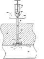
该例证的血管伤口封闭组件230能够精确地定位于皮下血管伤口w附近以便封闭伤口。具体参考图12和13,为了精确定位并接近股动脉伤口w,先将导管232在导线258上穿过,所述导线258已经预先通过穿刺伤口w插入患者的股动脉94。如图23-24最佳示出的那样,内腔244与抽气源264相连时,组件230在导线258上前进穿过患者组织,使得导管232的远端尖端240延伸穿过血管穿刺伤口w。The exemplary vascular
在推进组件230时,抽气源264通过孔260抽出体液。体液通过观察口268,使临床医生能够鉴别正在抽出的体液。观察口268能够具有任何适当的结构或位置。例如,观察口能够包含与导管连接的透明管、具有抽气源和观察口两种功能的基本透明的注射器或基本透明的部分导管。最优选地,导管232由透明材料形成,以便临床医生在血液一通过导管开始被抽出时就知道。As
如图23所示,在推进装置230时,套环360咬合患者皮肤。如图24所示,在进一步推进装置时,套环360继续咬合患者皮肤,并且输送管290相对于套管360向远端滑动。管相对于套环360滑动时,套环随着锥形输送管290的直径而张开,并且套环继续施加向内的圆周力以帮助管保持封闭。预计套环360远端的围绕部分输送管290的身体组织96也有助于使管保持封闭。As shown in FIG. 23, as
如图24所示,当孔260穿过动脉壁98并进入血管94时,血液“b”开始通过孔260被吸入导管232并经过观察口268进行传输。因此,当在观察口268观察到血液b时,临床医生会知道孔260刚刚进入穿刺伤口w并且输送管290的远端302因而位于动脉94的外壁98附近,优选在动脉壁98的1cm以内。As shown in FIG. 24 , when
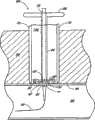
如图24所示,当装置230位于伤口w处或附近的期望位置时,释放连接元件352和帽346,使得推件元件300能够相对于输送管290和导管232前进。具体参考图25,在推进推进元件300时,推进元件300的远端328和/或封闭元件150的周界表面咬合管元件292、294的内表面308,从而迫使管元件292、294分开并从输送管腔室322内展开止血材料333和封闭环150。在图25中例证的实施方案中,管元件292、294具有柔韧性,使得它们在推进推进元件300和封闭环的驱动力下向外弯曲。As shown in FIG. 24 , when
如上所讨论的那样,在一实施方案中,止血材料333包含亲水性纤维壳聚糖毛绒,并且封闭环150包含相对较浓的亲水性纤维壳聚糖织物。由于毛绒和封闭元件是亲水性的,它们会粘住伤口w周围和身体组织96周围的血管98。此外,没有纤维材料通过伤口进入血管94。从伤口w移去导管232时,毛绒容易瓦解进入原先由导管占据的空间。毛绒333具有止血性质,并充分环绕伤口w,从而辅助伤口相对较快止血。As discussed above, in one embodiment, the
在某些实施方案中,组装封闭装置230,使得从导管孔260到输送管290远端302的距离约为或稍大于血管壁98的宽度。这样,输送管290紧靠伤口w布置。继续参考图24和25,在该例证的实施方案中,从导管孔260到输送管290远端302的距离比血管壁98的宽度大许多,但不超过1.5cm。更优选该距离不超过1cm。这样,当导管孔260进入血管94并且临床医生看到血液进入观察口268时,输送管290靠近血管壁98定位但与其有距离。在该例证的实施方案中,该间隔提供安全特性以确保输送管元件292、294的远端302不进入或损伤伤口位点w。止血材料333一展开,推进元件300就在导管232上推进材料333和封闭元件150,以接触或接近血管壁98和伤口w。根据另一实施方案,输送管290与血管壁98隔开至少约血管壁厚度3倍的距离。In certain embodiments,
继续参考图25,当如图所示管元件292、294随展开而张开时,管元件292、294向远端移动有了进一步的阻力,从而进一步提供安全性。此外,尽管套环360可在输送管290上滑动,但它对输送管290相对于套环360进一步向远端移动贡献某些摩擦阻力。With continued reference to FIG. 25, when the
若干类型的材料能够用于构造封闭元件150,这样的材料可以具有或不具有促进止血的性质。例如,能够使用弹性、非弹性、天然或人工材料及其组合。可以采用单独使用或与止血剂和/或粘合剂组合使用的聚合物材料。优选地,封闭元件由可生物降解的材料如聚乳酸(PLA)、壳聚糖或其它可生物降解的材料构成。另一优选类别的合适材料包括可以用于血管移植物的材料。用于构造封闭元件的另一优选材料包括可得自W.L.Gore and Associates,Inc.的Gore-Tex
在优选实施方案中,封闭元件150可以是纤维非纺织壳聚糖织物。由于其亲水性,壳聚糖封闭元件优选将与血管94的外表面98粘附。这进一步确保了封闭元件在血管上的适当位置,以防止任何松散止血材料进入血管。另外,壳聚糖封闭元件能够利用壳聚糖有利的促进止血性质,并将辅助促进血液凝结以封闭伤口。In a preferred embodiment, the
在某些实施方案中,由于所用材料或由于相对较高的密度,封闭元件为刚性或半刚性的。这样,封闭元件在压力下不会变形到止血材料能够通过封闭元件的远端并进入伤口。在其它实施方案中,封闭元件通常具有柔韧性。这样,它更容易适应血管94的形状。在这样的实施方案中,封闭元件优选具有足够大的外径,使得封闭元件不能穿过伤口w。In certain embodiments, the closure element is rigid or semi-rigid due to the materials used or due to its relatively high density. In this way, the closure element is not deformed under pressure to the extent that the hemostatic material can pass through the distal end of the closure element and into the wound. In other embodiments, the closure element is generally flexible. In this way, it is easier to adapt to the shape of the
在另一实施方案中,封闭元件由网状材料构成,所述网状材料包含足够细的网孔以至于能够防止纤维止血材料通过网孔,但有助于其中的血液通过并进入止血材料。在一实施方案中,网孔基本是刚性的并具有一定厚,以保持结构刚度和距离伤口w的间隔从而增强仪器的安全性。在另一实施方案中,网孔具有延展性以使使用更容易,但该网孔很坚固且在操作压力下不会破裂,所以它将保持其坚固的构造从而防止部分止血材料通过网孔进入伤口w。In another embodiment, the closure element is constructed of a mesh material comprising meshes fine enough to prevent passage of the fibrous hemostatic material through the mesh, but to facilitate passage of blood therein into the hemostatic material. In one embodiment, the mesh is substantially rigid and has a certain thickness to maintain structural rigidity and spacing from the wound w to enhance instrument safety. In another embodiment, the mesh is malleable to make it easier to use, but the mesh is strong and will not rupture under operating pressure, so it will maintain its strong configuration preventing part of the hemostatic material from entering through the mesh wound w.
参考接下来的图26和27,给出了封闭元件的另一实施方案150a。在该实施方案中,封闭元件150a的形状为具有外周界表面158和内孔160的环,并设置为可滑动地与导管232周围匹配。然而,封闭元件150a包含内孔封闭装置400,当从中移去导管232时,所述装置400一般适于封闭内孔160。在该例证的实施方案中,封闭装置400包含一对挠性片402、404,所述挠性片402、404适于向外弯曲以容纳导管232,但是在移去导管232时趋于回到它们的位置,优选彼此部分重叠。Referring next to Figures 26 and 27, another
如图27中最佳例证的那样,在该例证的实施方案中,将挠性片402、404并入封闭元件150a的主体152中。例如,在一实施方案中,最初单独制造封闭元件150a的下部406;片402、404安装在下部406上的适当位置;然后在下部406和片402、404部分的顶部形成封闭元件150a的上部408。这样,将片402、404固定地作为封闭元件150a的一部分,但部分片402、404横向延伸穿过内孔160。在另一实施方案中,片402、404可以与封闭元件150a的近端或远端表面154、156粘附。As best illustrated in Figure 27, in the illustrated embodiment,
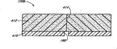
参考接下来的图28和29,给出了封闭元件150b的另一实施方案,其中封闭元件包含多种材料。在该例证的实施方案中,封闭元件150b的主体152包含下部410和上部412。下部410通常优选为半刚性的,适于咬合血管,并且包括有一定尺寸并且适于容纳定位导管232的内孔160。上部412通常优选具有弹性。Referring next to Figures 28 and 29, another embodiment of the
在优选实施方案中,上部412包含弹性泡沫,所述泡沫可变形但是适于一旦去掉变形力就恢复其原始形状。优选地,上部412包含通常与下部410的内孔160对准的穿刺口414、切口等。穿刺口414为导管提供通路,以便通过上部412并通过下部410的内孔160延伸。如图28详细示出的那样,部分的上部412在穿刺口414处和附近的发生变形(被压紧)以容纳导管232。如图29详细显出的那样,当移去导管232时,所述压紧的部分优选恢复其原始形状,优选堵住穿刺口414,并且还提供另一屏障以阻止止血材料穿过内孔160到达伤口w。In a preferred embodiment,
具有适于或易于当一移去导管就封闭内孔的封闭介质的封闭元件尤其适于与可能特别难以避免穿过小开口的止血材料如干粉一起使用。A closure element having a closure medium suitable or apt to close the bore upon removal of the catheter is particularly suitable for use with hemostatic materials such as dry powders which may be particularly difficult to avoid passing through small openings.
参考接下来的图30-32,给出了封闭元件150c和相应的推进元件420的实施方案。如图所示,封闭元件150c优选包含具有远端表面156、近端表面154和周界表面158的主体152。内孔160具有一定的尺寸并适于容纳穿过其中的伸长导管。多个伸长臂422从近端表面154向近端延伸。Referring to the following Figures 30-32, an embodiment of the
推进元件420优选包含具有近端426的伸长主体424,所述近端426具有远端表面428。多个伸长导轨430从远端表面428向近端延伸并在各自的终止壁432终止。优选导轨430的形状通常与臂422互补,使得臂422可滑动地容纳在导轨430中。具体参考图31,优选在封闭元件的近端表面154和推进元件的远端表面之间限定空间434。止血材料333优选置于空间434中。
具体参考图31和32,优选推进导轨430的长度小于封闭元件臂422的长度。这样,如图32所示,当臂422的近端436毗邻导轨430的终止壁432时,推进件420和封闭元件主体152之间的空间434得以保持。Referring specifically to FIGS. 31 and 32 , it is preferred that the length of the advancing
使用中,优选封闭元件150c和推进元件420最初互相咬合,止血材料333位于空间434中。如图31所示,优选封闭元件主体422布置在导轨430中,但与终止壁432隔开。导管(未示出)优选延伸穿过血管组件组成部分的推进件420和封闭元件150c。当将血管组件定位于血管伤口附近时,向远端推进推进元件420以展开封闭元件150c和止血材料333。封闭元件150c咬合伤口时,进一步向远端前进有了明显的阻力。最终推进件420相对于封闭元件150c向远端移动,从而压缩止血材料333。当臂422咬合导轨终止壁432时,这样的相对移动停止。这样,避免推进元件420过分压缩止血材料333。In use, preferably the
很多类型的操作涉及推进导管和/或其它手术器具穿过血管穿刺口以进行治疗、输送装置等。最常见的用于穿过股动脉的介入导管的尺寸不超过约6F。然而,预计可以使用大很多的导管和其它手术器具。本文讨论的封闭装置可以根据需要构造为多种不同的尺寸。优选封闭装置的导管232的直径大于封闭之前的操作中使用的导管和/或其它手术器具。优选地,导管232的直径约0-1F,且更优选约0.5F,大于较早使用的导管。在图12-25例证的实施方案中,导管232的尺寸优选约为6.5F。Many types of procedures involve advancing catheters and/or other surgical instruments through blood vessel punctures for treatment, delivery of devices, and the like. The most common interventional catheters used to pass through the femoral artery are no larger than about 6F in size. However, it is anticipated that much larger catheters and other surgical instruments could be used. The closure devices discussed herein can be constructed in a variety of different sizes as desired. Preferably, the diameter of the
由于封闭装置的导管232直径大于临床医生在封闭伤口之前使用的导管。导管232大到足以紧紧地咬合伤口边缘并且有效地堵住伤口。导管232相对于伤口w的紧密匹配进一步帮助阻止止血材料333穿过导管与伤口边缘之间并且进入血管94中。Due to the diameter of the
如以上所讨论的那样,优选实施方案的封闭元件的外径大于伤口和封闭装置导管的直径。封闭元件外径大于伤口直径的程度能够变化,但是优选选择当受到来自如推进元件的压力时消除推进元件会穿过伤口的风险。在优选实施方案中,封闭元件的外径为约2-6F,并且更优选约3-4F,大于伤口或临床操作期间进入伤口的最大装置。As discussed above, the outer diameter of the closure element of preferred embodiments is larger than the diameter of the wound and closure device conduit. The extent to which the outer diameter of the closure element is larger than the diameter of the wound can vary, but is preferably selected to eliminate the risk that the advancing element will pass through the wound when subjected to pressure from, for example, the advancing element. In preferred embodiments, the closure element has an outer diameter of about 2-6F, and more preferably about 3-4F, larger than the wound or the largest device that enters the wound during clinical procedures.
具有如本文讨论的实施方案中的方面的封闭装置尤其与封闭非常大的血管穿刺口相关。例如,越来越多的操作涉及穿过血管穿刺口输送较大治疗装置和/或修复物(例如心脏瓣膜或血管移植物)。这样的操作可以形成大的穿刺口,如10F、15F、甚至20F的穿刺口。为了在这样的操作之后封闭穿刺伤口,至少具有通常半刚性构造的封闭元件尤其有益,因为整个伤口都可以被封闭元件覆盖,以防止其它封闭介质进入伤口。封闭元件可以由不受穿刺口影响的部分血管支撑,从而封闭元件又会支撑血管的穿刺部分。这样,封闭元件不仅有助于封闭伤口,而且有助于支撑在治疗中可能变得脆弱的血管部分。Closure devices having aspects as in embodiments discussed herein are particularly relevant for sealing very large vascular punctures. For example, an increasing number of procedures involve delivering larger therapeutic devices and/or prostheses (eg, heart valves or vascular grafts) through vascular punctures. Such an operation can form a large puncture port, such as a 10F, 15F, or even a 20F puncture port. In order to seal the puncture wound after such manipulations, it is particularly advantageous to have at least a generally semi-rigid construction of the closure element, since the entire wound can be covered by the closure element in order to prevent further sealing media from entering the wound. The closure element can be supported by a part of the vessel which is not affected by the puncture opening, so that the closure element in turn supports the punctured part of the vessel. In this way, the closure element not only helps to seal the wound, but also helps to support portions of the blood vessel that may become vulnerable during treatment.
根据另一实施方案,如与图12-25描述的实施方案中相关的输送管290包含在其上印刷或以其它方式所作的标记。使用中,临床医生在最初穿刺血管期间记录穿刺深度。之后,在血管封闭期间,输送管290上的标记为临床医生提供参考以判定管相对于血管伤口的深度及位置。应当理解,这样的标记可以印刷在输送管上或者可以有形地形成于管的凸起或下凹部分。According to another embodiment, the
在另一实施方案中,可以在推进元件上提供标记。这样放置标记可以有助于使用者确定推进元件相对于输送管、导管和/或患者皮肤的位置,以便于帮助确定止血材料和封闭元件是否已经完全展开。In another embodiment, markings may be provided on the propulsion element. Such placement of markers may assist the user in determining the position of the advancement element relative to the delivery tube, catheter, and/or patient's skin in order to assist in determining whether the hemostatic material and closure element have been fully deployed.
应当理解,可以使用各种形状和尺寸的输送管。例如,参考接下来的图33和34,血管封闭装置的另一实施方案包含牵引件,所述牵引件包含一对反向的伸长牵引臂440。优选牵引件设置为当临床医生操作时选择性地打开和关闭牵引臂440。每一牵引臂440具有远端442和近端444。在远端和近端442、444处及紧邻远端和近端442、444形成通路446、447,并且如图34所示,通常设置为互补地容纳导管232a。优选牵引臂440的锥形部分448逐渐变细以便从远端442向近端移动时外径扩大。It should be understood that delivery tubes of various shapes and sizes may be used. For example, referring to FIGS. 33 and 34 next, another embodiment of a vessel closure device includes a puller comprising a pair of opposing elongated puller
每一牵引臂440至少部分中空,当彼此咬合时在所述牵引臂440之间限定腔室450。在最初锥形452之后,腔室450优选具有通常恒定的内径。如图34详细示出的那样,优选腔室450适于容纳具有封闭元件150安装于其上的导管232a,并且止血材料333布置在封闭元件150近端的腔室450中。在该例证的实施方案中,腔室450的最初锥形452通常很尖,使得封闭元件150与牵引臂440的远端442相对较近地布置。Each trailing
继续参考图33和34,在腔室450的近端442处限定近端腔室壁454。然而,提供通道455以容纳穿过其中延伸的导管232a。近端腔室壁454的近端处,在每一牵引臂440内形成空腔456。优选地,导管232a包含设置为互补地装入空腔456内的凸起部分458。这样,当牵引臂440与安装在其中的导管232a咬合使得导管凸起部分458被装进空腔456时,导管232a相对于牵引臂440纵向固定,并且组件可以整体移动而无需担心腔室450内的导管(因此封闭环)的位置可能发生混乱。With continued reference to FIGS. 33 and 34 , at the
根据另一实施方案,输送管可以构造为看起来类似于图12和13例证的组合管,除了形成单一片的管而不是可移动的两半的管。在一实施方案中,所述单片管包含一个或多个纵向伸长的弱部分。使用中,当施加力以推进推进元件时,力被推进元件和/或封闭元件导向输送管的内表面。这样的力打破弱部件,从而打开用于输送封闭元件和止血材料的通路。在一实施方案中,提供一对反向伸长的弱部分。在另一实施方案中,提供三个或更多这样的部分。在另一实施方案中,仅在输送管的远端部分提供弱部分。在另一实施方案中,弱部分沿输送管的整个长度延伸。According to another embodiment, the delivery tube may be configured to look similar to the composite tube illustrated in Figures 12 and 13, except forming a single piece of tube instead of two movable halves. In one embodiment, the monolithic tube comprises one or more longitudinally elongated weak portions. In use, when force is applied to advance the pusher element, the force is directed by the pusher element and/or the closure element to the inner surface of the delivery tube. Such a force breaks the weak part, thereby opening the passage for the delivery of the closure element and the hemostatic material. In one embodiment, a pair of oppositely elongated weak portions are provided. In another embodiment, three or more such portions are provided. In another embodiment, the weak portion is provided only at the distal portion of the delivery tube. In another embodiment, the weak portion extends along the entire length of the delivery tube.
参考接下来的图35,血管伤口封闭装置460的另一实施方案包含导管232b,其具有适于可滑动地容纳导线258的内腔244。优选地,导管232b包含穿过导管远端尖端234近端的导管232b侧壁形成的指示孔260。封闭件150可滑动地布置在导管232b上。如图所示,导管优选沿其长度包含凸起止动件462。优选凸起止动件462足够突起以防止封闭元件150沿导管232b向近端移动跃过止动件462。在一实施方案中,在导线258上推进装置460时,止动件462防止不需要的相对移动。在另一实施方案中,当将导管和封闭元件150装进输送管、牵引件腔室等时,止动件462能够帮助保持封闭元件150相对于导管232b的期望位置。Referring next to FIG. 35 , another embodiment of a vascular wound closure device 460 includes a catheter 232 b having a
推进元件464适于在导管232b上滑动。推进元件464包含具有远端推进表面468的伸长主体466。多个伸长推进臂470由推进表面468向远端延伸。在图35例证的实施方案中,推进臂470的远端472咬合封闭元件150的近端表面154。这样,在推进表面468与封闭元件150之间限定最小空间474。在该例证的实施方案中,空间474用止血材料333填充。在一实施方案中,臂470咬合封闭元件150并且能够独立于止血材料333向伤口推进封闭元件150;推进表面468咬合止血材料333,并且独立于封闭元件150向伤口推进止血材料。Pusher element 464 is adapted to slide over catheter 232b. Advancement element 464 includes an elongated body 466 having a distal advancement surface 468 . A plurality of elongated advancement arms 470 extend distally from advancement surface 468 . In the embodiment illustrated in FIG. 35 , the distal end 472 of the advancing arm 470 engages the
使用中,装置在导线258上推进,而通过导管232b抽真空直到血液抽过指示孔260,这表明封闭元件150位于血管伤口处或附近。然后向远端推进推进元件464,从而将封闭元件150和止血材料333推进至伤口位点而基本上不压紧止血材料333。在另一实施方案中,止血材料333的远端部分与封闭元件150的近端表面附着。这样,在推进期间,当推进件464向伤口推进封闭元件150时,封闭元件150在其后推进止血材料333。In use, the device is advanced over
在另一实施方案中,推进臂470相对于推进件用弹簧连接。这样,在推进件向伤口位点输送封闭元件和止血材料时,空间至少可以部分压缩。在另一实施方案中,推进元件臂的远端与封闭元件的近端表面适度连接。这样,当推进元件向伤口位点推进封闭元件和止血材料时,组件保持在一起。当被适当输送时,推进元件相对于封闭元件的扭曲打破适度的连接,并且可以移去推进件。In another embodiment, the pusher arm 470 is spring-coupled relative to the pusher. In this way, the space may be at least partially compressed as the pusher delivers the closure element and hemostatic material to the wound site. In another embodiment, the distal end of the pusher member arm is moderately connected to the proximal surface of the closure member. In this way, the assembly is held together as the advancing element advances the closure element and hemostatic material toward the wound site. When properly delivered, twisting of the pusher element relative to the closure element breaks the modest connection and the pusher can be removed.
参考接下来的图36和37,提供另一实施方案,其中血管伤口封闭组件480在导线258上推进,穿过伸长护套482并且到达血管伤口w。在该例证的实施方案中,到伤口w处或附近位置的通路由护套482保持。血管伤口封闭组件480包含具有内孔160的封闭元件150,所述内孔160的内径尺寸适于容纳导线258。该例证的实施方案不采用导管,尽管预计其它实施方案可以采用导管。止血材料333布置在封闭元件150近端的导线258上方。如图37所示,伸长推进元件484设置为在导线258上向远端推进止血材料333和封闭元件150,通过护套482并与血管w接触。Referring next to Figures 36 and 37, another embodiment is provided wherein a vascular
在该例证的实施方案中,推进元件484在其侧面印有标记486。相对护套482的长度校准标记486,因而能够指示推进元件484相对于护套482的位置。这样,临床医生能够确定封闭元件150和止血材料333是否已经向远端推进到足以适当地咬合血管外壁98,从而封闭伤口w。In the illustrated embodiment, the
可以使用多种方法将护套482放置在适当的位置。在一实施方案中,先将空心针插入血管,并推进导线258穿过该针并进入血管,将针移去。引导护套能够在导线258上推进,并可以进入血管94。横截面增加的外护套能够在引导护套上方前进。然而,由于其直径大,外护套不进入血管,尽管在操作中引导护套作为通路引导治疗介质进入血管94。优选在治疗操作完成并从血管移去引导护套后,外护套仍保持在合适的位置。这样,外护套482为血管伤口封闭组件480提供通路。The
参考接下来的图38,公开了袋或囊490。优选地,囊490包含通常为伸长圆环面形状的伸长体492。这样,穿过囊490形成伸长孔494。在优选实施方案中,囊490包含纤维网状材料496并适于在其中封入止血材料。在另一实施方案中,囊490包含一旦暴露于身体组织就易于降解的材料。例如,囊490可以由干燥凝胶状材料形成,一旦暴露于包括血液在内的潮湿的身体组织,所述材料就吸收水分并溶化,从而暴露其中的止血材料。Referring next to Figure 38, a bag or
还参考图39,在一实施方案中,可以在导管232上和封闭元件150的近端布置囊490。这样,囊490能够用作本文讨论的实施方案的变化。提供推进元件498以在导管232上推进囊和封闭元件150。参考图40,在另一实施方案中,囊490(如网状囊)其自身用作在伤口w和囊内的止血材料之间布置的封闭元件。由于该网状结构,止血材料包含在该囊内。然而,血液能够流过网孔496进入止血材料,促使同样也能够通过网孔496进行的凝血级联。Referring also to FIG. 39 , in one embodiment, a
在另一实施方案中,不采用环绕的网状囊,而是可以将止血材料置于网状盘中。该盘在其远端并沿侧面包含挠性的、半刚性的或通常为刚性的网状或筛状材料,但该盘在其近端是开口的。In another embodiment, instead of using a surrounding mesh capsule, the hemostatic material can be placed in a mesh disc. The disc contains flexible, semi-rigid or generally rigid mesh or mesh material at its distal end and along the sides, but is open at its proximal end.
根据另一实施方案,在工具包中提供具有上述实施方案中的特征的血管伤口封闭装置供临床医生使用。在该实施方案中,优选由适当的一次性材料,如医用级塑料形成该装置,并且组装并装载所述装置使得组件彼此可拆卸地连接,并且将止血材料置于输送管。尽管可以提供预先组装的该装置,但是临床医生仍然可以通过拆开管和推进元件,做出调整然后重新连接管和推进元件来调节管相对于导管的位置。该装置是灭菌的并优选置于封闭的、灭菌的容器(未示出)中,所述容器设置为在无菌环境如操作室或导管实验室中打开。According to another embodiment, a vascular wound closure device having the features of the above embodiments is provided in a kit for use by a clinician. In this embodiment, the device is preferably formed from a suitable disposable material, such as medical grade plastic, and assembled and loaded such that the components are detachably connected to each other and the hemostatic material is placed in the delivery tube. Although the device can be provided pre-assembled, the clinician can still adjust the position of the tube relative to the catheter by disassembling the tube and advancement element, making adjustments and then reconnecting the tube and advancement element. The device is sterile and preferably placed in a closed, sterile container (not shown) that is configured to be opened in a sterile environment such as a procedure room or catheterization laboratory.
尽管本公开给出了某些优选实施方案和实施例,但本领域技术人员将会理解,本发明延伸到具体公开的实施方案之外,到达其它可替换的实施方案和/或用途以及其显而易见的变化和相同物。另外,虽然已经详细示出并描述了很多变化,但在本发明范围内的其它变化基于本公开对本领域技术人员将是显而易见的。也预计可以做出所述实施方案具体特征和方面的多种组合或亚组合,并且仍然落入本发明范围之内。例如,与图35例证的实施方案有关的凸起止动件能够适当地与图12-25讨论的实施方案结合。因此,应当理解,本公开的实施方案的多种特征和方面能够彼此组合或替换以形成所公开的发明的变化模式。因此,在此处公开的本发明的范围应当不受上述公开的具体实施方案的限制,而是应当仅通过合理解释下列权利要求来确定。While the present disclosure presents certain preferred embodiments and examples, those skilled in the art will appreciate that the invention extends beyond the specifically disclosed embodiments to other alternative embodiments and/or uses as well as obviousness thereof. Variations and similitudes. In addition, while many variations have been shown and described in detail, other variations within the scope of the invention will be apparent to those skilled in the art from this disclosure. It is also contemplated that various combinations or sub-combinations of specific features and aspects of the described embodiments can be made and still fall within the scope of the invention. For example, the raised stops associated with the embodiment illustrated in Figure 35 can be suitably combined with the embodiments discussed in Figures 12-25. It should therefore be appreciated that various features and aspects of the disclosed embodiments can be combined with or substituted for one another in order to form varying modes of the disclosed invention. Accordingly, the scope of the present invention herein disclosed should not be limited by the particular embodiments disclosed above, but should be determined only by reasonable interpretation of the following claims.
Claims (18)
Applications Claiming Priority (3)
| Application Number | Priority Date | Filing Date | Title |
|---|---|---|---|
| US72372305P | 2005-10-05 | 2005-10-05 | |
| US60/723,723 | 2005-10-05 | ||
| PCT/US2006/039112WO2007044510A1 (en) | 2005-10-05 | 2006-10-05 | Vascular wound closure device and method |
Publications (2)
| Publication Number | Publication Date |
|---|---|
| CN101495047A CN101495047A (en) | 2009-07-29 |
| CN101495047Btrue CN101495047B (en) | 2011-12-28 |
Family
ID=37685955
Family Applications (1)
| Application Number | Title | Priority Date | Filing Date |
|---|---|---|---|
| CN2006800372741AExpired - Fee RelatedCN101495047B (en) | 2005-10-05 | 2006-10-05 | Vascular wound closure device and method |
Country Status (7)
| Country | Link |
|---|---|
| US (4) | US8088145B2 (en) |
| EP (1) | EP1965707B1 (en) |
| JP (2) | JP5253170B2 (en) |
| CN (1) | CN101495047B (en) |
| AT (1) | ATE499882T1 (en) |
| DE (1) | DE602006020488D1 (en) |
| WO (1) | WO2007044510A1 (en) |
Families Citing this family (117)
| Publication number | Priority date | Publication date | Assignee | Title |
|---|---|---|---|---|
| US6287322B1 (en)* | 1995-12-07 | 2001-09-11 | Loma Linda University Medical Center | Tissue opening locator and everter and method |
| US6391048B1 (en) | 2000-01-05 | 2002-05-21 | Integrated Vascular Systems, Inc. | Integrated vascular device with puncture site closure component and sealant and methods of use |
| US8758400B2 (en) | 2000-01-05 | 2014-06-24 | Integrated Vascular Systems, Inc. | Closure system and methods of use |
| US9579091B2 (en) | 2000-01-05 | 2017-02-28 | Integrated Vascular Systems, Inc. | Closure system and methods of use |
| US7842068B2 (en) | 2000-12-07 | 2010-11-30 | Integrated Vascular Systems, Inc. | Apparatus and methods for providing tactile feedback while delivering a closure device |
| US6461364B1 (en) | 2000-01-05 | 2002-10-08 | Integrated Vascular Systems, Inc. | Vascular sheath with bioabsorbable puncture site closure apparatus and methods of use |
| US6890342B2 (en) | 2000-08-02 | 2005-05-10 | Loma Linda University | Method and apparatus for closing vascular puncture using hemostatic material |
| DE60144328D1 (en) | 2000-09-08 | 2011-05-12 | Abbott Vascular Inc | Surgical clamp |
| US6626918B1 (en) | 2000-10-06 | 2003-09-30 | Medical Technology Group | Apparatus and methods for positioning a vascular sheath |
| US7905900B2 (en) | 2003-01-30 | 2011-03-15 | Integrated Vascular Systems, Inc. | Clip applier and methods of use |
| US6623510B2 (en) | 2000-12-07 | 2003-09-23 | Integrated Vascular Systems, Inc. | Closure device and methods for making and using them |
| US6695867B2 (en) | 2002-02-21 | 2004-02-24 | Integrated Vascular Systems, Inc. | Plunger apparatus and methods for delivering a closure device |
| US8690910B2 (en) | 2000-12-07 | 2014-04-08 | Integrated Vascular Systems, Inc. | Closure device and methods for making and using them |
| US7211101B2 (en) | 2000-12-07 | 2007-05-01 | Abbott Vascular Devices | Methods for manufacturing a clip and clip |
| IES20010547A2 (en) | 2001-06-07 | 2002-12-11 | Christy Cummins | Surgical Staple |
| IES20030424A2 (en) | 2002-06-04 | 2003-12-10 | Robert Stevenson | Blood vessel closure clip and delivery device |
| ATE342000T1 (en)* | 2002-06-14 | 2006-11-15 | Univ Loma Linda Med | DEVICE FOR CLOSING VASCULAR WOUNDS |
| US8398656B2 (en) | 2003-01-30 | 2013-03-19 | Integrated Vascular Systems, Inc. | Clip applier and methods of use |
| US8758398B2 (en) | 2006-09-08 | 2014-06-24 | Integrated Vascular Systems, Inc. | Apparatus and method for delivering a closure element |
| US8202293B2 (en) | 2003-01-30 | 2012-06-19 | Integrated Vascular Systems, Inc. | Clip applier and methods of use |
| US8821534B2 (en) | 2010-12-06 | 2014-09-02 | Integrated Vascular Systems, Inc. | Clip applier having improved hemostasis and methods of use |
| US8905937B2 (en) | 2009-02-26 | 2014-12-09 | Integrated Vascular Systems, Inc. | Methods and apparatus for locating a surface of a body lumen |
| DE602004031953D1 (en) | 2003-08-14 | 2011-05-05 | Univ Loma Linda Med | |
| US8187627B2 (en)* | 2003-09-05 | 2012-05-29 | Loma Linda University Medical Center | Dressing delivery system for internal wounds |
| IES20040368A2 (en) | 2004-05-25 | 2005-11-30 | James E Coleman | Surgical stapler |
| US8926633B2 (en) | 2005-06-24 | 2015-01-06 | Abbott Laboratories | Apparatus and method for delivering a closure element |
| US8313497B2 (en) | 2005-07-01 | 2012-11-20 | Abbott Laboratories | Clip applier and methods of use |
| JP5253170B2 (en) | 2005-10-05 | 2013-07-31 | ローマ リンダ ユニヴァーシティ メディカル センター | Vascular wound closure device and method |
| US8613728B2 (en) | 2005-11-07 | 2013-12-24 | Flexicath Ltd. | Removable adapter for a splittable introducer and method of use thereof |
| US8808310B2 (en) | 2006-04-20 | 2014-08-19 | Integrated Vascular Systems, Inc. | Resettable clip applier and reset tools |
| US8556930B2 (en) | 2006-06-28 | 2013-10-15 | Abbott Laboratories | Vessel closure device |
| US20080255447A1 (en)* | 2007-04-16 | 2008-10-16 | Henry Bourang | Diagnostic catheter |
| US8568445B2 (en)* | 2007-08-21 | 2013-10-29 | St. Jude Medical Puerto Rico Llc | Extra-vascular sealing device and method |
| US8333787B2 (en) | 2007-12-31 | 2012-12-18 | St. Jude Medical Puerto Rico Llc | Vascular closure device having a flowable sealing material |
| AU2008318560B2 (en)* | 2007-10-31 | 2014-12-04 | Cardinal Health 529, Llc | Method of making a vascular closure device |
| US8893947B2 (en) | 2007-12-17 | 2014-11-25 | Abbott Laboratories | Clip applier and methods of use |
| US20090157101A1 (en)* | 2007-12-17 | 2009-06-18 | Abbott Laboratories | Tissue closure system and methods of use |
| US7841502B2 (en) | 2007-12-18 | 2010-11-30 | Abbott Laboratories | Modular clip applier |
| US8840640B2 (en)* | 2007-12-31 | 2014-09-23 | St. Jude Medical Puerto Rico Llc | Vascular closure device having an improved plug |
| CA2820166C (en)* | 2008-03-14 | 2016-05-24 | Cordis Corporation | Vascular closure device |
| JP2009273559A (en)* | 2008-05-13 | 2009-11-26 | Tokyo Iken Kk | Hemostatic device |
| WO2009140376A1 (en)* | 2008-05-13 | 2009-11-19 | Kci Licensing, Inc. | Catheter/filament style device and methods for treatment of wounds beneath the surface of the skin |
| US9282965B2 (en) | 2008-05-16 | 2016-03-15 | Abbott Laboratories | Apparatus and methods for engaging tissue |
| US8425527B2 (en) | 2008-07-07 | 2013-04-23 | Medtronic Xomed, Inc. | Cavitation depth, perforation confirmation and implant delivery tool |
| WO2010018447A1 (en)* | 2008-08-13 | 2010-02-18 | Del Corso, Andrea | Occlusion device for vascular surgery |
| US8398676B2 (en)* | 2008-10-30 | 2013-03-19 | Abbott Vascular Inc. | Closure device |
| US8858594B2 (en) | 2008-12-22 | 2014-10-14 | Abbott Laboratories | Curved closure device |
| US8323312B2 (en) | 2008-12-22 | 2012-12-04 | Abbott Laboratories | Closure device |
| US20110218568A1 (en)* | 2009-01-09 | 2011-09-08 | Voss Laveille K | Vessel closure devices, systems, and methods |
| US9414820B2 (en) | 2009-01-09 | 2016-08-16 | Abbott Vascular Inc. | Closure devices, systems, and methods |
| US9089311B2 (en) | 2009-01-09 | 2015-07-28 | Abbott Vascular Inc. | Vessel closure devices and methods |
| US20100179589A1 (en) | 2009-01-09 | 2010-07-15 | Abbott Vascular Inc. | Rapidly eroding anchor |
| US9486191B2 (en) | 2009-01-09 | 2016-11-08 | Abbott Vascular, Inc. | Closure devices |
| US9173644B2 (en) | 2009-01-09 | 2015-11-03 | Abbott Vascular Inc. | Closure devices, systems, and methods |
| US20100185234A1 (en) | 2009-01-16 | 2010-07-22 | Abbott Vascular Inc. | Closure devices, systems, and methods |
| EP3181074A1 (en) | 2009-01-30 | 2017-06-21 | St. Jude Medical, Inc. | Transapical mini-introducer homeostasis valve and punch |
| US9839415B2 (en)* | 2009-01-30 | 2017-12-12 | St. Jude Medical, Llc | Apex closure device |
| EP2216054A1 (en)* | 2009-02-06 | 2010-08-11 | ProFibrix BV | Biodegradable extravascular support |
| US20100241163A1 (en)* | 2009-03-23 | 2010-09-23 | Medtronic Vascular, Inc. | Aortic Dissection Treatment System and Method of Use |
| WO2011017031A2 (en)* | 2009-07-27 | 2011-02-10 | The Regents Of The University Of California | Prohealing endovascular devices |
| US20110054492A1 (en) | 2009-08-26 | 2011-03-03 | Abbott Laboratories | Medical device for repairing a fistula |
| US9408595B2 (en)* | 2009-08-31 | 2016-08-09 | St. Jude Medical Puerto Rico Llc | Monorail system for vascular closure device and methods |
| DE102009040220A1 (en)* | 2009-09-07 | 2011-03-17 | Rheinisch-Westfälische Technische Hochschule Aachen | An introducer system for introducing a device into a blood vessel, method and introducer device |
| US8623274B2 (en) | 2009-11-25 | 2014-01-07 | Loma Linda University Medical Center | Chitosan-based hemostatic textile |
| US9993236B2 (en) | 2009-12-08 | 2018-06-12 | Phillips Medical, LLC | Hemostatic device and its methods of use |
| US9179900B2 (en)* | 2009-12-08 | 2015-11-10 | Phillips Medical Llc | Hemostatic device and its methods of use |
| AU2010334552B2 (en) | 2009-12-27 | 2014-04-17 | Covidien Lp | Medical device |
| EP2560556B1 (en) | 2010-04-19 | 2016-10-12 | Phillips Medical LLC | A hemostatic device |
| US8758399B2 (en) | 2010-08-02 | 2014-06-24 | Abbott Cardiovascular Systems, Inc. | Expandable bioabsorbable plug apparatus and method |
| US8603116B2 (en) | 2010-08-04 | 2013-12-10 | Abbott Cardiovascular Systems, Inc. | Closure device with long tines |
| US20120283758A1 (en)* | 2011-01-11 | 2012-11-08 | Arnold Miller | Method and apparatus for treating varicose veins |
| AU2012212070A1 (en) | 2011-02-04 | 2013-09-19 | University Of Massachusetts | Negative pressure wound closure device |
| US9421132B2 (en) | 2011-02-04 | 2016-08-23 | University Of Massachusetts | Negative pressure wound closure device |
| EP2497426B1 (en)* | 2011-03-09 | 2016-12-14 | Aeeg Ab | Device and kit for closure of a body lumen puncture |
| US9149276B2 (en) | 2011-03-21 | 2015-10-06 | Abbott Cardiovascular Systems, Inc. | Clip and deployment apparatus for tissue closure |
| US9332976B2 (en) | 2011-11-30 | 2016-05-10 | Abbott Cardiovascular Systems, Inc. | Tissue closure device |
| EP2793990A4 (en)* | 2011-12-21 | 2016-03-02 | Walkill Concepts Inc | Self-sealing catheters |
| US9642604B2 (en) | 2012-04-12 | 2017-05-09 | Phillips Medical Llc | Hemostatic system and its methods of use |
| EP2852333B1 (en) | 2012-05-22 | 2021-12-15 | Smith & Nephew plc | Apparatuses for wound therapy |
| EP2852419B1 (en) | 2012-05-22 | 2019-11-20 | Smith & Nephew plc | Wound closure device |
| AU2013264937B2 (en) | 2012-05-24 | 2018-04-19 | Smith & Nephew Inc. | Devices and methods for treating and closing wounds with negative pressure |
| US9468428B2 (en) | 2012-06-13 | 2016-10-18 | Phillips Medical Llc | Hemostatic device and its methods of use |
| MX369689B (en) | 2012-07-16 | 2019-11-19 | Smith & Nephew Inc | Negative pressure wound closure device. |
| US20140039598A1 (en)* | 2012-07-30 | 2014-02-06 | Gregory C. Sampognaro | Blood loss control system |
| US9364209B2 (en) | 2012-12-21 | 2016-06-14 | Abbott Cardiovascular Systems, Inc. | Articulating suturing device |
| US9107646B2 (en)* | 2013-03-11 | 2015-08-18 | St. Jude Medical Puerto Rico Llc | Active securement detachable sealing tip for extra-vascular closure device and methods |
| US10124098B2 (en) | 2013-03-13 | 2018-11-13 | Smith & Nephew, Inc. | Negative pressure wound closure device and systems and methods of use in treating wounds with negative pressure |
| BR112015021123A2 (en) | 2013-03-14 | 2017-07-18 | Smith & Nephew | compressible wound fillers and systems and methods for use in treating negative pressure injuries |
| US9610069B2 (en)* | 2013-04-26 | 2017-04-04 | Medtronic-Xomed, Inc. | Tissue stabilization and repair device |
| US9724081B2 (en)* | 2013-06-04 | 2017-08-08 | Phillips Medical Llc | Hemostatic system and its methods of use |
| US10085730B2 (en) | 2013-07-12 | 2018-10-02 | Phillips Medical, LLC | Hemostatic device and its methods of use |
| US9839416B2 (en)* | 2013-07-12 | 2017-12-12 | Phillips Medical, LLC | Hemostatic device and its methods of use |
| CN106170275B (en) | 2013-10-21 | 2021-05-07 | 史密夫和内修有限公司 | Negative pressure wound closure device |
| AU2015208299B2 (en) | 2014-01-21 | 2019-11-21 | Smith & Nephew Plc | Collapsible dressing for negative pressure wound treatment |
| US9259357B2 (en) | 2014-04-16 | 2016-02-16 | Loma Linda University | Composition, preparation, and use of chitosan shards for biomedical applications |
| WO2015171390A1 (en)* | 2014-05-07 | 2015-11-12 | Avent, Inc. | Medical port with replaceable catheter |
| MA40946A (en)* | 2014-11-14 | 2017-09-19 | Access Closure Inc | APPARATUS AND METHODS FOR MAKING A VASCULAR PUNCTURE WATERTIGHT |
| CN104665897B (en)* | 2015-02-16 | 2017-11-07 | 中国人民解放军第二军医大学 | A kind of ejected wave knife for preventing pneumothorax from occurring follows the trail of label implantation puncture needle |
| AU2016254119A1 (en) | 2015-04-29 | 2017-10-05 | Smith & Nephew Inc. | Negative pressure wound closure device |
| CN104998334A (en)* | 2015-05-27 | 2015-10-28 | 黄志辉 | Artery sheath and artery sheath application method |
| JP6564639B2 (en)* | 2015-07-16 | 2019-08-21 | テルモ株式会社 | Hemostatic device |
| CN105147394A (en)* | 2015-08-21 | 2015-12-16 | 江苏海泽医疗科技发展有限公司 | Multifunctional protective sleeve for wound of soft tissue during operation |
| US10575991B2 (en) | 2015-12-15 | 2020-03-03 | University Of Massachusetts | Negative pressure wound closure devices and methods |
| US11471586B2 (en) | 2015-12-15 | 2022-10-18 | University Of Massachusetts | Negative pressure wound closure devices and methods |
| US10814049B2 (en) | 2015-12-15 | 2020-10-27 | University Of Massachusetts | Negative pressure wound closure devices and methods |
| TW201738256A (en)* | 2016-04-04 | 2017-11-01 | 日產化學工業股份有限公司 | Production method of protein |
| EP3457948B1 (en)* | 2016-05-20 | 2020-07-01 | Vivasure Medical Limited | Vascular closure device |
| JP6797612B2 (en)* | 2016-09-01 | 2020-12-09 | テルモ株式会社 | Introducer sheath |
| US10515474B2 (en)* | 2017-01-19 | 2019-12-24 | Mindmaze Holding Sa | System, method and apparatus for detecting facial expression in a virtual reality system |
| DE102018208555A1 (en) | 2018-05-30 | 2019-12-05 | Kardion Gmbh | Apparatus for anchoring a cardiac assist system in a blood vessel, method of operation, and method of making a device and cardiac assist system |
| CN110522499B (en)* | 2019-09-26 | 2020-07-28 | 济南市儿童医院(山东大学齐鲁儿童医院) | Blood vessel puncture sealing device |
| CN114945346A (en)* | 2020-01-16 | 2022-08-26 | 爱德华兹生命科学公司 | System and method for fluid control |
| EP4192565A1 (en)* | 2020-08-07 | 2023-06-14 | Kardion GmbH | Peel-away introducer sheath having an adjustable diameter |
| CN111839647A (en)* | 2020-08-11 | 2020-10-30 | 首都医科大学附属北京世纪坛医院 | An arterial hemostatic device |
| US12383246B2 (en) | 2020-10-12 | 2025-08-12 | Abbott Cardiovascular Systems, Inc. | Vessel closure device with improved safety and tract hemostasis |
| DE102022205130A1 (en)* | 2022-05-23 | 2023-11-23 | B. Braun Melsungen Aktiengesellschaft | Catheter assembly for use in peripheral regional anesthesia |
| KR102685423B1 (en)* | 2023-11-10 | 2024-07-15 | 박성철 | Stent delivery system and device comprising the same |
Citations (1)
| Publication number | Priority date | Publication date | Assignee | Title |
|---|---|---|---|---|
| US5320639A (en)* | 1993-03-12 | 1994-06-14 | Meadox Medicals, Inc. | Vascular plug delivery system |
Family Cites Families (139)
| Publication number | Priority date | Publication date | Assignee | Title |
|---|---|---|---|---|
| US1064307A (en)* | 1912-08-28 | 1913-06-10 | William T Remington | Syringe. |
| US1344020A (en)* | 1919-06-11 | 1920-06-22 | Bugbee Coy Macmillan | Tongue-depressor |
| US1741457A (en)* | 1925-02-04 | 1929-12-31 | Glass Jacob | Surgical appliance |
| US2370660A (en)* | 1943-09-06 | 1945-03-06 | Guardite Corp | Means for opening and closing pressure containers |
| US3677244A (en)* | 1969-08-04 | 1972-07-18 | Extracorporeal Med Spec | Removable catheter needle |
| US3653388A (en)* | 1969-12-04 | 1972-04-04 | Battelle Development Corp | Catheter insertion trocar |
| US3827438A (en)* | 1972-07-10 | 1974-08-06 | G Kees | Aneurysm clip |
| US4024868A (en)* | 1975-02-03 | 1977-05-24 | Robert W Williams | Permanent aneurysm clamp |
| US4060080A (en) | 1975-03-17 | 1977-11-29 | Taichiro Akiyama | Plug for living body |
| US4166469A (en)* | 1977-12-13 | 1979-09-04 | Littleford Philip O | Apparatus and method for inserting an electrode |
| US4900303A (en)* | 1978-03-10 | 1990-02-13 | Lemelson Jerome H | Dispensing catheter and method |
| US4306562A (en)* | 1978-12-01 | 1981-12-22 | Cook, Inc. | Tear apart cannula |
| US4532134A (en)* | 1981-04-06 | 1985-07-30 | Malette William Graham | Method of achieving hemostasis, inhibiting fibroplasia, and promoting tissue regeneration in a tissue wound |
| DE3117802A1 (en)* | 1981-05-06 | 1982-11-25 | Max Dr. 8520 Erlangen Hubmann | CATHETER CUTLERY |
| JPS61240963A (en)* | 1985-04-18 | 1986-10-27 | ユニチカ株式会社 | Wound covering protective material |
| US4622970A (en) | 1985-08-29 | 1986-11-18 | The Johns Hopkins University | Vascular everting instrument |
| US4744363A (en)* | 1986-07-07 | 1988-05-17 | Hasson Harrith M | Intra-abdominal organ stabilizer, retractor and tissue manipulator |
| US4738658A (en)* | 1986-09-19 | 1988-04-19 | Aries Medical Incorporated | Tapered hemostatic device for use in conjunction with a catheter for alleviating blood leakage and method for using same |
| US4889112A (en) | 1987-01-23 | 1989-12-26 | Waltap Ltd. | Apparatus for performing a tracheostomy operation |
| US4890612A (en)* | 1987-02-17 | 1990-01-02 | Kensey Nash Corporation | Device for sealing percutaneous puncture in a vessel |
| US4772266A (en)* | 1987-05-04 | 1988-09-20 | Catheter Technology Corp. | Catheter dilator/sheath assembly and method |
| US4921479A (en)* | 1987-10-02 | 1990-05-01 | Joseph Grayzel | Catheter sheath with longitudinal seam |
| FR2641692A1 (en)* | 1989-01-17 | 1990-07-20 | Nippon Zeon Co | Plug for closing an opening for a medical application, and device for the closure plug making use thereof |
| US5011478A (en)* | 1989-01-31 | 1991-04-30 | Cook Incorporation | Recessed dilator-sheath assembly and method |
| US5620461A (en)* | 1989-05-29 | 1997-04-15 | Muijs Van De Moer; Wouter M. | Sealing device |
| US5057083A (en) | 1989-07-25 | 1991-10-15 | C. R. Bard, Inc. | Vascular dilator with truncated tip |
| JP2528602B2 (en)* | 1989-12-04 | 1996-08-28 | ケンゼー・ナッシュ・コーポレーション | Plug device for sealing the opening |
| US5391183A (en)* | 1990-09-21 | 1995-02-21 | Datascope Investment Corp | Device and method sealing puncture wounds |
| US5419765A (en)* | 1990-12-27 | 1995-05-30 | Novoste Corporation | Wound treating device and method for treating wounds |
| US5129882A (en)* | 1990-12-27 | 1992-07-14 | Novoste Corporation | Wound clotting device and method of using same |
| US6325789B1 (en) | 1990-12-27 | 2001-12-04 | Datascope Investment Corporation | Device and method for sealing puncture wounds |
| US5183464A (en)* | 1991-05-17 | 1993-02-02 | Interventional Thermodynamics, Inc. | Radially expandable dilator |
| US5125904B1 (en)* | 1991-07-09 | 1996-11-19 | Hl Medical Inventions Inc | Splittable hemostatic valve sheath and the method for using the same |
| US5312355A (en)* | 1991-07-09 | 1994-05-17 | H L Medical Inventions, Inc. | Splittable hemostatic valve and sheath and the method for using the same |
| US5259835A (en) | 1991-08-29 | 1993-11-09 | Tri-Point Medical L.P. | Wound closure means and method using flowable adhesive |
| CA2078530A1 (en)* | 1991-09-23 | 1993-03-24 | Jay Erlebacher | Percutaneous arterial puncture seal device and insertion tool therefore |
| US5290310A (en)* | 1991-10-30 | 1994-03-01 | Howmedica, Inc. | Hemostatic implant introducer |
| US5222974A (en)* | 1991-11-08 | 1993-06-29 | Kensey Nash Corporation | Hemostatic puncture closure system and method of use |
| US5411520A (en)* | 1991-11-08 | 1995-05-02 | Kensey Nash Corporation | Hemostatic vessel puncture closure system utilizing a plug located within the puncture tract spaced from the vessel, and method of use |
| US5282827A (en) | 1991-11-08 | 1994-02-01 | Kensey Nash Corporation | Hemostatic puncture closure system and method of use |
| US5676689A (en) | 1991-11-08 | 1997-10-14 | Kensey Nash Corporation | Hemostatic puncture closure system including vessel location device and method of use |
| US6056768A (en)* | 1992-01-07 | 2000-05-02 | Cates; Christopher U. | Blood vessel sealing system |
| US6699261B1 (en)* | 1992-01-07 | 2004-03-02 | Cch Associates, Inc. | Blood vessel sealing system |
| US5236455A (en)* | 1992-02-10 | 1993-08-17 | Wilk Peter J | Tympanic patch, applicator, and related method |
| CA2089999A1 (en)* | 1992-02-24 | 1993-08-25 | H. Jonathan Tovey | Resilient arm mesh deployer |
| US5810810A (en) | 1992-04-23 | 1998-09-22 | Scimed Life Systems, Inc. | Apparatus and method for sealing vascular punctures |
| US5242387A (en) | 1992-05-08 | 1993-09-07 | Brigham & Women's Hospital | Suction-irrigator |
| US5292332A (en)* | 1992-07-27 | 1994-03-08 | Lee Benjamin I | Methods and device for percutanceous sealing of arterial puncture sites |
| US5342393A (en)* | 1992-08-27 | 1994-08-30 | Duke University | Method and device for vascular repair |
| US5397311A (en)* | 1992-09-09 | 1995-03-14 | Menlo Care, Inc. | Bloodless splittable introducer |
| US5306254A (en)* | 1992-10-01 | 1994-04-26 | Kensey Nash Corporation | Vessel position locating device and method of use |
| US5250033A (en) | 1992-10-28 | 1993-10-05 | Interventional Thermodynamics, Inc. | Peel-away introducer sheath having proximal fitting |
| US5552452A (en) | 1993-03-15 | 1996-09-03 | Arch Development Corp. | Organic tissue glue for closure of wounds |
| US5626601A (en)* | 1995-10-27 | 1997-05-06 | Gary Gershony | Vascular sealing apparatus and method |
| US5383896A (en)* | 1993-05-25 | 1995-01-24 | Gershony; Gary | Vascular sealing device |
| US5486195A (en)* | 1993-07-26 | 1996-01-23 | Myers; Gene | Method and apparatus for arteriotomy closure |
| US5431639A (en)* | 1993-08-12 | 1995-07-11 | Boston Scientific Corporation | Treating wounds caused by medical procedures |
| NL9301526A (en) | 1993-09-03 | 1995-04-03 | Cordis Europ | Device for hemostasis treatment after catheter surgery. |
| US5383899A (en)* | 1993-09-28 | 1995-01-24 | Hammerslag; Julius G. | Method of using a surface opening adhesive sealer |
| US5653730A (en)* | 1993-09-28 | 1997-08-05 | Hemodynamics, Inc. | Surface opening adhesive sealer |
| US5759194A (en)* | 1993-09-28 | 1998-06-02 | Hemodynamics, Inc. | Vascular patch applicator |
| US5843124A (en)* | 1993-09-28 | 1998-12-01 | Hemodynamics, Inc. | Surface opening adhesive sealer |
| US5370660A (en)* | 1993-11-01 | 1994-12-06 | Cordis Corporation | Apparatus and method for delivering a vessel plug into the body of a patient |
| US5658298A (en)* | 1993-11-09 | 1997-08-19 | Inamed Development Company | Laparoscopic tool |
| US5460621A (en) | 1994-03-04 | 1995-10-24 | Merocel Corporation | Composite tissue displacement sponge |
| WO1995026683A1 (en)* | 1994-03-31 | 1995-10-12 | Boston Scientific Corporation | Vascular plug with vessel locator |
| US5545178A (en)* | 1994-04-29 | 1996-08-13 | Kensey Nash Corporation | System for closing a percutaneous puncture formed by a trocar to prevent tissue at the puncture from herniating |
| US5531759A (en)* | 1994-04-29 | 1996-07-02 | Kensey Nash Corporation | System for closing a percutaneous puncture formed by a trocar to prevent tissue at the puncture from herniating |
| US5549633A (en)* | 1994-08-24 | 1996-08-27 | Kensey Nash Corporation | Apparatus and methods of use for preventing blood seepage at a percutaneous puncture site |
| WO1996010374A1 (en) | 1994-10-03 | 1996-04-11 | Otogen Corporation | Differentially biodegradable biomedical implants |
| AU1965895A (en) | 1995-02-07 | 1996-08-27 | Cardiovascular Ventures, Inc. | Puncture sealing system |
| US5649959A (en)* | 1995-02-10 | 1997-07-22 | Sherwood Medical Company | Assembly for sealing a puncture in a vessel |
| JP3633032B2 (en) | 1995-05-26 | 2005-03-30 | 佐々木 寛 | Puncture device |
| US6071300A (en)* | 1995-09-15 | 2000-06-06 | Sub-Q Inc. | Apparatus and method for percutaneous sealing of blood vessel punctures |
| US5645566A (en)* | 1995-09-15 | 1997-07-08 | Sub Q Inc. | Apparatus and method for percutaneous sealing of blood vessel punctures |
| JP4185165B2 (en) | 1995-12-07 | 2008-11-26 | ローマ リンダ ユニヴァーシティ メディカル センター | Vascular wound closure device |
| US6425901B1 (en) | 1995-12-07 | 2002-07-30 | Loma Linda University Medical Center | Vascular wound closure system |
| US6004341A (en) | 1996-12-05 | 1999-12-21 | Loma Linda University Medical Center | Vascular wound closure device |
| US6524326B1 (en) | 1995-12-07 | 2003-02-25 | Loma Linda University Medical Center | Tissue opening locator and everter and method |
| US6287322B1 (en) | 1995-12-07 | 2001-09-11 | Loma Linda University Medical Center | Tissue opening locator and everter and method |
| US5814065A (en) | 1996-02-09 | 1998-09-29 | Cordis Corporation | Suture delivery tool |
| JP2000510357A (en) | 1996-04-04 | 2000-08-15 | イムノ・アクチエンゲゼルシャフト | Hemostatic sponge based on collagen |
| US5728132A (en)* | 1996-04-08 | 1998-03-17 | Tricardia, L.L.C. | Self-sealing vascular access device |
| US5662681A (en)* | 1996-04-23 | 1997-09-02 | Kensey Nash Corporation | Self locking closure for sealing percutaneous punctures |
| US5776096A (en)* | 1996-06-06 | 1998-07-07 | Hdc Corporation | Dual lumen vascular catheter with expanding side portal |
| US5728133A (en) | 1996-07-09 | 1998-03-17 | Cardiologics, L.L.C. | Anchoring device and method for sealing percutaneous punctures in vessels |
| US5836970A (en) | 1996-08-02 | 1998-11-17 | The Kendall Company | Hemostatic wound dressing |
| WO1998005259A1 (en)* | 1996-08-06 | 1998-02-12 | Quinton Instrument Company | Insertion assembly and method of inserting a hemostatic closure device into an incision |
| EP0873145A2 (en)* | 1996-11-15 | 1998-10-28 | Advanced Bio Surfaces, Inc. | Biomaterial system for in situ tissue repair |
| US6371975B2 (en)* | 1998-11-06 | 2002-04-16 | Neomend, Inc. | Compositions, systems, and methods for creating in situ, chemically cross-linked, mechanical barriers |
| US6146373A (en) | 1997-10-17 | 2000-11-14 | Micro Therapeutics, Inc. | Catheter system and method for injection of a liquid embolic composition and a solidification agent |
| WO1999022646A1 (en)* | 1997-10-31 | 1999-05-14 | Sherwood Services Ag | Hemostatic puncture closure device |
| US5906631A (en)* | 1997-12-05 | 1999-05-25 | Surface Genesis, Inc. | Method and device for sealing vascular puncture wounds |
| AU1923199A (en) | 1997-12-17 | 1999-07-05 | Hemodynamics, Inc. | Sealing media for surgery and wound closure |
| US5910155A (en)* | 1998-06-05 | 1999-06-08 | United States Surgical Corporation | Vascular wound closure system |
| US6048358A (en)* | 1998-07-13 | 2000-04-11 | Barak; Shlomo | Method and apparatus for hemostasis following arterial catheterization |
| AU758665B2 (en) | 1998-07-22 | 2003-03-27 | Angiolink Corporation | Vascular suction cannula, dilator and surgical stapler |
| US6613070B2 (en)* | 1998-08-04 | 2003-09-02 | Baxter International Inc. | System and method for sealing vascular penetrations with hemostatic gels |
| AUPP633798A0 (en) | 1998-10-02 | 1998-10-29 | White, Geoffrey H. | Device for the occlusion of a puncture in a bodily duct |
| US6949114B2 (en)* | 1998-11-06 | 2005-09-27 | Neomend, Inc. | Systems, methods, and compositions for achieving closure of vascular puncture sites |
| WO2000033744A1 (en) | 1998-12-08 | 2000-06-15 | University Of Virginia Patent Foundation | Device and technique for percutaneous closure of vascular puncture sites |
| US6060461A (en)* | 1999-02-08 | 2000-05-09 | Drake; James Franklin | Topically applied clotting material |
| US6808509B1 (en)* | 1999-04-22 | 2004-10-26 | Scimed Life Systems, Inc. | Valved introducer sheath and related methods |
| US6110184A (en) | 1999-08-04 | 2000-08-29 | Weadock; Kevin S. | Introducer with vascular sealing mechanism |
| US6461364B1 (en) | 2000-01-05 | 2002-10-08 | Integrated Vascular Systems, Inc. | Vascular sheath with bioabsorbable puncture site closure apparatus and methods of use |
| US6197042B1 (en)* | 2000-01-05 | 2001-03-06 | Medical Technology Group, Inc. | Vascular sheath with puncture site closure apparatus and methods of use |
| US7842068B2 (en)* | 2000-12-07 | 2010-11-30 | Integrated Vascular Systems, Inc. | Apparatus and methods for providing tactile feedback while delivering a closure device |
| EP1259168B1 (en) | 2000-02-24 | 2010-09-08 | Loma Linda University Medical Center | Patch and glue delivery system for closing tissue openings during surgery |
| US20020022822A1 (en)* | 2000-07-14 | 2002-02-21 | Cragg Andrew H. | Sheath-mounted arterial plug delivery device |
| US6890342B2 (en)* | 2000-08-02 | 2005-05-10 | Loma Linda University | Method and apparatus for closing vascular puncture using hemostatic material |
| US7201725B1 (en)* | 2000-09-25 | 2007-04-10 | Sub-Q, Inc. | Device and method for determining a depth of an incision |
| US6508828B1 (en)* | 2000-11-03 | 2003-01-21 | Radi Medical Systems Ab | Sealing device and wound closure device |
| US6695867B2 (en)* | 2002-02-21 | 2004-02-24 | Integrated Vascular Systems, Inc. | Plunger apparatus and methods for delivering a closure device |
| US6846319B2 (en)* | 2000-12-14 | 2005-01-25 | Core Medical, Inc. | Devices for sealing openings through tissue and apparatus and methods for delivering them |
| US6969397B2 (en)* | 2000-12-14 | 2005-11-29 | Ensure Medical, Inc. | Guide wire element for positioning vascular closure devices and methods for use |
| US6520939B2 (en)* | 2001-02-13 | 2003-02-18 | Scimed Life Systems, Inc. | Hemostasis valve |
| US20020147496A1 (en) | 2001-04-06 | 2002-10-10 | Integrated Vascular Systems, Inc. | Apparatus for treating spinal discs |
| US20030044380A1 (en) | 2001-07-19 | 2003-03-06 | Zhu Yong Hua | Adhesive including medicament |
| US7066934B2 (en)* | 2001-07-19 | 2006-06-27 | Loma Linda University | Adhesive including medicament and device and method for applying same |
| US8465516B2 (en)* | 2001-07-26 | 2013-06-18 | Oregon Health Science University | Bodily lumen closure apparatus and method |
| US6776784B2 (en)* | 2001-09-06 | 2004-08-17 | Core Medical, Inc. | Clip apparatus for closing septal defects and methods of use |
| US20030109820A1 (en)* | 2001-12-07 | 2003-06-12 | Gross T. Daniel | Hemostatic agent delivery system |
| US6897348B2 (en)* | 2001-12-19 | 2005-05-24 | Kimberly Clark Worldwide, Inc | Bandage, methods of producing and using same |
| US20030125264A1 (en) | 2001-12-29 | 2003-07-03 | Kimberly-Clark Worldwide, Inc. | Methods For Treating Wounds |
| ATE342000T1 (en)* | 2002-06-14 | 2006-11-15 | Univ Loma Linda Med | DEVICE FOR CLOSING VASCULAR WOUNDS |
| ES2295272T3 (en)* | 2002-09-04 | 2008-04-16 | Endoart S.A. | CLOSURE SYSTEM FOR SURGICAL RING. |
| US7092765B2 (en)* | 2002-09-23 | 2006-08-15 | Medtronic, Inc. | Non-sheath based medical device delivery system |
| US8709038B2 (en)* | 2002-12-20 | 2014-04-29 | Boston Scientific Scimed, Inc. | Puncture hole sealing device |
| US6896809B2 (en)* | 2002-12-20 | 2005-05-24 | Providence Health System - Oregon | Methods for purifying chitosan |
| AU2004253463B2 (en)* | 2003-06-16 | 2010-12-09 | Loma Linda University Medical Center | Deployable multifunctional hemostatic agent |
| US20050118238A1 (en)* | 2003-06-16 | 2005-06-02 | Zhu Yong H. | Deployable hemostatic agent |
| DE602004031953D1 (en)* | 2003-08-14 | 2011-05-05 | Univ Loma Linda Med | |
| US8187627B2 (en)* | 2003-09-05 | 2012-05-29 | Loma Linda University Medical Center | Dressing delivery system for internal wounds |
| US7361183B2 (en)* | 2003-10-17 | 2008-04-22 | Ensure Medical, Inc. | Locator and delivery device and method of use |
| JP4223417B2 (en)* | 2004-02-23 | 2009-02-12 | テルモ株式会社 | In vivo tissue closure device |
| CN101897989B (en) | 2004-02-23 | 2013-11-13 | 洛马林达大学医学中心 | Hemostatic agent for topical and internal use |
| US8262693B2 (en)* | 2004-11-05 | 2012-09-11 | Accessclosure, Inc. | Apparatus and methods for sealing a vascular puncture |
| JP5253170B2 (en) | 2005-10-05 | 2013-07-31 | ローマ リンダ ユニヴァーシティ メディカル センター | Vascular wound closure device and method |
| EP2330981B1 (en)* | 2008-08-26 | 2013-11-27 | St. Jude Medical, Inc. | System for sealing percutaneous punctures |
- 2006
- 2006-10-05JPJP2008534704Apatent/JP5253170B2/ennot_activeExpired - Fee Related
- 2006-10-05WOPCT/US2006/039112patent/WO2007044510A1/enactiveApplication Filing
- 2006-10-05USUS11/544,793patent/US8088145B2/ennot_activeExpired - Fee Related
- 2006-10-05CNCN2006800372741Apatent/CN101495047B/ennot_activeExpired - Fee Related
- 2006-10-05ATAT06816391Tpatent/ATE499882T1/ennot_activeIP Right Cessation
- 2006-10-05EPEP06816391Apatent/EP1965707B1/ennot_activeNot-in-force
- 2006-10-05DEDE602006020488Tpatent/DE602006020488D1/enactiveActive
- 2011
- 2011-12-01USUS13/308,922patent/US8617253B2/ennot_activeExpired - Fee Related
- 2012
- 2012-12-07JPJP2012268425Apatent/JP2013066745A/enactivePending
- 2013
- 2013-10-31USUS14/069,118patent/US9179902B2/ennot_activeExpired - Fee Related
- 2015
- 2015-10-15USUS14/884,433patent/US20160030025A1/ennot_activeAbandoned
Patent Citations (1)
| Publication number | Priority date | Publication date | Assignee | Title |
|---|---|---|---|---|
| US5320639A (en)* | 1993-03-12 | 1994-06-14 | Meadox Medicals, Inc. | Vascular plug delivery system |
Also Published As
| Publication number | Publication date |
|---|---|
| DE602006020488D1 (en) | 2011-04-14 |
| JP2009517094A (en) | 2009-04-30 |
| US20160030025A1 (en) | 2016-02-04 |
| US20140058443A1 (en) | 2014-02-27 |
| JP2013066745A (en) | 2013-04-18 |
| ATE499882T1 (en) | 2011-03-15 |
| US8088145B2 (en) | 2012-01-03 |
| JP5253170B2 (en) | 2013-07-31 |
| US20070123816A1 (en) | 2007-05-31 |
| US8617253B2 (en) | 2013-12-31 |
| CN101495047A (en) | 2009-07-29 |
| US20120143246A1 (en) | 2012-06-07 |
| EP1965707A1 (en) | 2008-09-10 |
| US9179902B2 (en) | 2015-11-10 |
| EP1965707B1 (en) | 2011-03-02 |
| WO2007044510A1 (en) | 2007-04-19 |
Similar Documents
| Publication | Publication Date | Title |
|---|---|---|
| CN101495047B (en) | Vascular wound closure device and method | |
| US9101731B2 (en) | Vascular wound closure device and method | |
| EP2345371B1 (en) | Vascular wound closure device | |
| US6890342B2 (en) | Method and apparatus for closing vascular puncture using hemostatic material | |
| CA2801969C (en) | Vascular wound closure device | |
| AU2011218678B2 (en) | Vascular Wound Closure Device |
Legal Events
| Date | Code | Title | Description |
|---|---|---|---|
| C06 | Publication | ||
| PB01 | Publication | ||
| C10 | Entry into substantive examination | ||
| SE01 | Entry into force of request for substantive examination | ||
| C14 | Grant of patent or utility model | ||
| GR01 | Patent grant | ||
| CF01 | Termination of patent right due to non-payment of annual fee | Granted publication date:20111228 Termination date:20141005 | |
| EXPY | Termination of patent right or utility model |