CN101494143B - Switch electric appliance with control and protection function - Google Patents
Switch electric appliance with control and protection functionDownload PDFInfo
- Publication number
- CN101494143B CN101494143BCN2008100043552ACN200810004355ACN101494143BCN 101494143 BCN101494143 BCN 101494143BCN 2008100043552 ACN2008100043552 ACN 2008100043552ACN 200810004355 ACN200810004355 ACN 200810004355ACN 101494143 BCN101494143 BCN 101494143B
- Authority
- CN
- China
- Prior art keywords
- control
- contact
- electromagnet
- voltage
- operating mechanism
- Prior art date
- Legal status (The legal status is an assumption and is not a legal conclusion. Google has not performed a legal analysis and makes no representation as to the accuracy of the status listed.)
- Active
Links
- 238000004891communicationMethods0.000claimsabstractdescription25
- 230000007246mechanismEffects0.000claimsdescription64
- 230000005540biological transmissionEffects0.000claimsdescription30
- 230000003068static effectEffects0.000claimsdescription28
- 238000006243chemical reactionMethods0.000claimsdescription24
- 230000004907fluxEffects0.000claimsdescription23
- 238000012545processingMethods0.000claimsdescription20
- 238000000034methodMethods0.000claimsdescription11
- 238000012544monitoring processMethods0.000claimsdescription11
- 230000009471actionEffects0.000claimsdescription8
- 230000008569processEffects0.000claimsdescription8
- 239000004020conductorSubstances0.000claimsdescription3
- 230000000694effectsEffects0.000claimsdescription2
- 230000000087stabilizing effectEffects0.000claims1
- 238000003756stirringMethods0.000claims1
- 238000013519translationMethods0.000claims1
- 238000010586diagramMethods0.000description5
- 230000006978adaptationEffects0.000description4
- 238000004519manufacturing processMethods0.000description3
- VAYOSLLFUXYJDT-RDTXWAMCSA-NLysergic acid diethylamideChemical classC1=CC(C=2[C@H](N(C)C[C@@H](C=2)C(=O)N(CC)CC)C2)=C3C2=CNC3=C1VAYOSLLFUXYJDT-RDTXWAMCSA-N0.000description2
- 238000005760Tripper reactionMethods0.000description2
- 230000007547defectEffects0.000description2
- 238000005516engineering processMethods0.000description2
- 238000009434installationMethods0.000description2
- 230000001012protectorEffects0.000description2
- 238000004458analytical methodMethods0.000description1
- 230000009286beneficial effectEffects0.000description1
- 230000007423decreaseEffects0.000description1
- 230000007812deficiencyEffects0.000description1
- 238000013461designMethods0.000description1
- 238000011161developmentMethods0.000description1
- 238000009826distributionMethods0.000description1
- 230000011664signalingEffects0.000description1
- 230000006641stabilisationEffects0.000description1
- 238000011105stabilizationMethods0.000description1
- 239000007858starting materialSubstances0.000description1
- 238000003860storageMethods0.000description1
- 238000012546transferMethods0.000description1
Images


Landscapes
- Breakers (AREA)
Abstract
Translated fromChinese
Description
Translated fromChinese技术领域technical field
本发明涉及一种具有控制和保护功能的开关电器,特别是用于电动机控制和保护的具有接触器和断路器功能的开关电器。The invention relates to a switching device with control and protection functions, especially a switching device with the functions of a contactor and a circuit breaker for motor control and protection.
背景技术Background technique
断路器一般用于配电线路,接触器一般用于控制系统。接触器具有频繁操作的能力和较长的寿命,但不具有过载、短路保护功能以及较高的开断性能,而断路器具有较好的过载、短路保护功能和较高的开断性能,但不能频繁操作及寿命相对较短。但是有相当一些用电设备不仅要求能够实现频繁操作而且要求能够实现过载和短路保护。而具有控制和保护功能的开关电器,其控制功能利用接触器的电磁铁部件实现,通过人为断开或接通电磁铁部件的电源,就能实现断开和接通带有电机等负载的主电路;其保护功能利用断路器的脱扣器部件实现,当脱扣器监测到至少一根线路上存在如过载、短路等电气故障时,立即促使操作机构动作,从而断开主电路。Circuit breakers are generally used in distribution lines, and contactors are generally used in control systems. The contactor has the ability to operate frequently and has a long life, but it does not have overload and short-circuit protection functions and high breaking performance, while the circuit breaker has good overload and short-circuit protection functions and high breaking performance, but It cannot be operated frequently and has a relatively short lifespan. However, there are quite a few electrical equipment that require not only frequent operation but also overload and short-circuit protection. For switching appliances with control and protection functions, the control function is realized by the electromagnet part of the contactor. By artificially disconnecting or connecting the power supply of the electromagnet part, it can realize disconnection and connection of the main load with the motor and other loads. Circuit; its protection function is realized by the release part of the circuit breaker. When the release detects electrical faults such as overload and short circuit on at least one line, it immediately prompts the operating mechanism to act, thereby disconnecting the main circuit.
传统的具有控制和保护功能的开关电器的作法是同时使用分立器件保护一个用电设备,即同时使用断路器、接触器、电动机保护器或热继电器、起动器等,这样为了保护一个用电设备,同时要多个开关电器配合使用,并且还要使用大量的机械连接和电气连接,既浪费资源又浪费空间,接线及安装烦琐,并且要考虑多个开关电器的配合使用问题。The traditional method of switching electrical appliances with control and protection functions is to use discrete devices to protect an electrical equipment at the same time, that is, to use circuit breakers, contactors, motor protectors or thermal relays, starters, etc. at the same time, so that in order to protect an electrical equipment , At the same time, multiple switching devices must be used together, and a large number of mechanical connections and electrical connections must be used, which wastes resources and space, wiring and installation are cumbersome, and the use of multiple switching devices must be considered.
现有的一种具有接触器和断路器功能的开关电器,其脱扣保护器采用机械式,此类开关电器的缺点是需要大量的开关,否则不能满足所需范围的电源电压和电源电流的要求。An existing switching device with the functions of a contactor and a circuit breaker uses a mechanical trip protector. The disadvantage of this type of switching device is that it requires a large number of switches, otherwise it cannot meet the required range of power supply voltage and power supply current. Require.
现有的另一种具有接触器和断路器功能的开关电器,其电磁铁在接触器模式和断路器模式下对触头进行开关控制,这种电磁铁混合用作接触器模式和断路器模式的工作特点,不能满足在断路器模式下需要快速分断的要求。Another existing switching device with the functions of a contactor and a circuit breaker, its electromagnet performs switching control on the contacts in the contactor mode and the circuit breaker mode, and this electromagnet is used in both contactor mode and circuit breaker mode The working characteristics of the circuit breaker cannot meet the requirements of fast breaking in the circuit breaker mode.
ZL00813988.1的发明专利公开了现有的又一种具有接触器和断路器功能的开关电器,该专利采用了电磁铁、电磁跳闸装置、保护装置和控制机构,其中电磁跳闸装置与控制机构一起使用,保护装置通过控制线连接到电磁铁上,并通过跳闸线路连接到控制机构上。该已有技术的主要前提条件是:电磁铁为在预定电压下工作的DC型电磁铁,不管电源电压为AC型或DC型,均需要先通过适配电路将电源电压转变为预定电压以向电磁铁供电。这种必需增加电压转换、适配和稳压电路的直流磁系统,不仅结构复杂、成本高,且因增加转换电路会导致产品的可靠性下降。再有,该已有技术的短路保护倍数不能按用户要求在现场设定,可能会造成短路倍数太大而不能有效保护用电设备,不能充分满足用户的使用要求,造成产品的安全保护性能下降。此外,脱扣器的品种繁多,由于这种电器的脱扣等级和用电设备的电极类型不能设定,会使用户在采购过程中增加出错率,管理、运输、储备不方便、不经济。还有,这种电器的电磁铁、电磁跳闸装置需分别通过控制机构及其滑动或枢转装置作用在动触头上,很显然,这种多个控制机构和滑动或枢转装置分别作用于动触头的结构十分复杂,不仅制造成本很高,而且还限制了如辅助触头组等参与对动、静触头闭合/断开状态的控制或监测的附件的接入数量,从而大大降低了产品的使用性能,显著增加了产品的生产成本。The invention patent of ZL00813988.1 discloses another existing switching device with the function of contactor and circuit breaker. The patent uses electromagnet, electromagnetic tripping device, protection device and control mechanism, wherein the electromagnetic tripping device and the control mechanism In use, the protection device is connected to the electromagnet through the control line and connected to the control mechanism through the trip line. The main premise of this prior art is: the electromagnet is a DC type electromagnet working at a predetermined voltage, no matter the power supply voltage is AC type or DC type, it is necessary to first convert the power supply voltage to a predetermined voltage through an adaptation circuit to The electromagnet is powered. This kind of DC magnetic system, which must add voltage conversion, adaptation and voltage stabilization circuits, not only has a complex structure and high cost, but also reduces the reliability of the product due to the addition of conversion circuits. Furthermore, the short-circuit protection multiple of this prior art cannot be set on site according to user requirements, which may cause the short-circuit multiple to be too large to effectively protect electrical equipment, and cannot fully meet the user's requirements for use, resulting in a decline in the safety protection performance of the product . In addition, there are many types of trippers. Since the tripping level of this electrical appliance and the electrode type of the electrical equipment cannot be set, the user will increase the error rate in the procurement process, and the management, transportation, and storage are inconvenient and uneconomical. In addition, the electromagnet and the electromagnetic tripping device of this electrical appliance need to act on the moving contact through the control mechanism and its sliding or pivoting device respectively. Obviously, these multiple control mechanisms and sliding or pivoting devices act on the The structure of the moving contact is very complicated, not only the manufacturing cost is high, but also the number of accessories that participate in the control or monitoring of the closing/opening state of the moving and static contacts, such as the auxiliary contact group, is limited, thereby greatly reducing The use performance of the product is significantly increased, and the production cost of the product is significantly increased.
发明内容Contents of the invention
本发明的目的在于针对目前现有技术的设计不足,提供一种具有控制和保护功能的开关电器,采用交、直流可互换式模块化结构磁系统,脱扣器、辅助触头和通信模块分别为可互换的模块,而且多个辅助触头模块和通信模块可根据用户需要有选择地接入,本发明的开关电器不仅具有可根据电压类型和额定电流选配脱扣器的功能,而且还具有可在现场自行设定过载和短路保护整定倍数、脱扣等级和负载电机极数的功能,适配性能极佳,具有极好的扩展性,附件接入具有极好的互换性,所需的产品型号少和附件的品种、类型少,开关整体结构紧凑、体积小、寿命长,大大降低了制造成本,方便了用户的使用和管理,提高了产品的适用范围和可靠性。The purpose of the present invention is to address the design deficiencies of the current prior art, to provide a switching device with control and protection functions, which adopts AC and DC interchangeable modular structure magnetic systems, releases, auxiliary contacts and communication modules They are interchangeable modules, and multiple auxiliary contact modules and communication modules can be selectively connected according to user needs. The switching device of the present invention not only has the function of selecting a release according to the voltage type and rated current, Moreover, it also has the function of setting the overload and short-circuit protection setting multiple, tripping level and load motor poles on site. It has excellent adaptability, excellent scalability, and excellent interchangeability for accessing accessories. , the required product models are less and the varieties and types of accessories are less, the overall structure of the switch is compact, the volume is small, and the service life is long, which greatly reduces the manufacturing cost, facilitates the use and management of users, and improves the scope of application and reliability of the product.
为了实现上述目的,本发明具有控制和保护功能的开关电器采用了以下技术方案:在由底座95和可安装到底座95上的罩壳99所共同构成的外壳内,容纳有供通信模块或功能模块112接入的接线端子及安装空间,还容纳有:至少一对可分、合的静触头93和动触头92及其分别与电源导体16、17相连接的主电路电源端子106和主电路负载端子105,外壳内还包括电磁铁40,用于执行动触头92与静触头93的闭合/断开操作,开关48,串联连接于所述控制电源端子108与电磁铁40之间,用于控制电磁铁40的通/断,操作机构60,用于控制静触头93和动触头92闭合/断开,并控制开关48的通/断,手动操作钮61,包括一个磁通适配器52和一个电压变换电路80,用于人为控制操作机构60执行动触头92和静触头93闭合/断开任务,脱扣器50,由电流互感器55和处理电路53构成,电流互感器55将检测到的过载/短路电流信号通过控制导线531输送到处理电路53,处理电路53能对电流互感器55监测到的过载/短路电流信号进行分析处理,并通过控制线532向所述的磁通适配器52输出跳闸指令,由所述磁通适配器52驱动操作机构60跳闸,一对控制电源端子108,分别通过电源导线101a、101b与电磁铁40、电压变换电路80的输入端并联连接,所述的电压变换电路80的输出端分别通过连接导线102、103并联连接到磁通适配器52和脱扣器50中的处理电路53上,以将控制电源端子108分别作为电磁铁40、磁通适配器52和处理电路53的电源,当手动操作钮61作手动合闸/分闸操作时,所述的开关48在操作机构60的控制下接通/断开,控制电磁铁40、磁通适配器52和处理电路53的电源的同时通/断,从而完成手动合闸/分闸操作,当出现故障时,处理电路53根据电流互感器55监测到的过载/短路信号,向磁通适配器52输出跳闸指令,直接驱使动、静触头快速断开,开关48断开,使电磁铁40、磁通适配器52和处理电路53处于断电状态,从而完成自动跳闸操作。In order to achieve the above-mentioned purpose, the switching device with control and protection functions of the present invention adopts the following technical scheme: in the shell composed of the
所述电器还包括一个传动装置20,它直接承受由包括电磁铁40和操作机构60在内的用于控制动、静触头的合闸/分闸/跳闸的控制组件附件产生的机械动作,并传递给动触头92的触头支持11;还包括至少两个辅助触头模块100、104和/或其它监测附件和/或控制附件,它们与传动装置20发生如下的机械动作的作用关系,即,动、静触头的闭合/断开的机械动作直接作用于传动装置20,并通过传动装置20传递给辅助触头模块104、100;所述传动装置20上可接入的控制附件和监测附件的接口数可扩展到2个以上,以对动、静触头的闭合/断开提供更多更广的控制和监测。The electric appliance also includes a
所述的控制电源端子108的电压类型为交流电压或直流电压,所述的电磁铁40的电压类型根据控制电源端子108的电压类型选配;或者反之,所述的电磁铁40的电压类型为交流电压或直流电压,所述的控制电源端子108的电压类型根据电磁铁40的电压类型配置。The voltage type of the control
所述的电压变换电路80的输入端的电压与电磁铁40的电压相同,其输出端的电压为预定直流电压;所述的电压变换电路80用于将控制电源端子108的交流或直流电压转换为预定直流电压,以分别向磁通适配器52和处理电路53供电。所述的电压变换电路80由桥式整流电路、降压或升压电路、稳压变换电路中的一种或几种组合构成。The voltage at the input terminal of the
所述的脱扣器50设置在操作机构60和/或电磁铁40的下方,设有可由用户在现场设定过载/短路保护电流整定倍数、脱扣等级和负载的电极极数的设置,可由用户根据额定电流选择互换。所述的手动操作钮61为按钮、或旋转钮、旋转手柄、或拔动手柄。The
在罩壳99上设有接口和空间,所述接口用于供2个及以上的辅助触头模块100、104和/或其它监测附件和/或控制附件以可互换和插拔的方式接入,所述空间设置在所述操作机构60的上方,所述的操作机构60位于电磁铁40的上方或侧面。Interfaces and spaces are provided on the
所述的动触头92设置在一个接触桥19的两端,所述的接触桥19的一侧安装在触头支持11中且一侧与触头支持定位面相邻,所述的接触桥19的另一侧与弹簧15连接,所述的触头支持11受所述的传动装置20控制,在合闸状态时,传动装置20与触头支持11不接触,以使动触头92在弹簧15的弹力作用下与静触头93接触闭合,并在动、静触头之间形成稳定的接触力;在跳闸或分闸过程中,传动装置20始终与触头支持11接触,并驱使动触头92克服弹簧15的弹力作与静触头93分离的运动,从而使动、静触头断开。The moving
所述电器由上、下两层结构组件组成,底座95内设置有静触头93、动触头92、灭弧室94、触头支持11、弹簧15,它们组成下层底座组件951;罩壳99内设置有电磁铁40、脱扣器50、操作机构60、开关48、传动装置20、辅助触头模块100、104、通信模块或功能模块112,组成上层罩壳组件991。所述的电磁铁40设置在罩壳99的大致中间位置,操作机构60设置在电磁铁40的上边,脱扣器50设置在电磁铁40的下边,操作机构60、电磁铁40和脱扣器50成“三”字形排列。所述的电磁铁40设置在罩壳99的大致中间靠边位置,操作机构60与电磁铁40平行设置,脱扣器50设置在电磁铁40和操作机构60的下边,脱扣器50、电磁铁40和操作机构60成倒“品”字形排列。按台阶状三层结构布置各接线端子,以使客户区别与接线,主电路电源端子106和主电路负载端子105设置在底座95上,布置在第一层台阶上,控制电源端子108、辅助触头模块的指令端子107、109设置在罩壳99上,布置在第二层和/或第三层台阶上,并且,控制电源端子108布置在辅助触头模块的指令端子107、109侧面的第二或第三层台阶上。The electrical appliance is composed of upper and lower structural components. The
所述的通信模块或功能模块112设置罩壳99内,与脱扣器50相连,位于脱扣器50下方的空腔内,为可互换型插拔式独立模块。The communication module or
下面根据具有控制和保护功能的开关电器的两个用途特点,与现有技术对比说明本发明的有益技术效果。The beneficial technical effect of the present invention will be described below in comparison with the prior art according to the two application characteristics of the switching device with control and protection functions.
所述开关电器的用途特点之一,是它连接于某种用电设备与电源之间,由于各种用电设备的电压类型、电极极数、额定电流、短路保护倍数和脱扣等级等要求不同,所以开关电器的适配性能是其十分重要的性能指标。所述的适配性能,是指同一型号的开关设备能适配多种用电设备和能满足多种电压类型、电极极数、额定电流、短路保护整定倍数、脱扣等级的要求的性能。现有技术如ZL00813988.1专利采用保护模块可互换以解决额定电流的适配问题,但未解决电压类型、短路保护和脱扣等级的适配问题,而且额定电流的适配仅是采用保护模块的互换的方法,而不能由用户在现场自行设定。很显然,这种已有电器的适配性很差,一是需要按额定电流不同配置多种型号的保护模块附件,二是由于保护模块附件的品种有限,使用户可选择的范围受到限制。本发明的脱扣器不仅可根据用电设备的电压类型和额定电流选取配置,而且还可以由用户在现场设定过载/短路保护整定倍数、脱扣等级和负载电极极数。因此,本发明的技术方案,不仅可最大限度的减少可互换脱扣器的品种型号,而且还可为用户提供极为广泛的短路保护和脱扣等级的选择范围。One of the characteristics of the use of the switching device is that it is connected between a certain electrical equipment and the power supply. Different, so the adaptation performance of the switching device is a very important performance index. The adaptability mentioned above refers to the performance that the switchgear of the same type can adapt to various electrical equipment and meet the requirements of various voltage types, number of poles, rated current, short-circuit protection setting multiple, and tripping level. Existing technology such as ZL00813988.1 patent uses interchangeable protection modules to solve the problem of adapting the rated current, but it does not solve the problem of adapting the voltage type, short-circuit protection and trip level, and the adaptation of the rated current is only the use of protection The exchange method of the modules cannot be set by the user on site. Obviously, the adaptability of this existing electrical appliance is very poor. First, it is necessary to configure various types of protection module accessories according to the rated current. Second, due to the limited variety of protection module accessories, the range of choices for users is limited. The tripper of the present invention can not only be selected and configured according to the voltage type and rated current of the electrical equipment, but also can be set by the user on site to set the overload/short circuit protection setting multiple, trip level and load pole number. Therefore, the technical solution of the present invention can not only reduce the varieties and models of the interchangeable trippers to the greatest extent, but also provide users with a very wide selection range of short-circuit protection and tripping levels.
具有控制和保护功能的开关电器的用途特点之二,是需要有选择地可互换地配置多种控制和监测辅件,其中最为重要的也是使用最为普遍的辅件如辅助触头、通信模块或功能模块。因此,具有控制和保护功能的开关电器本体能否兼容和是否设有供多种类型和型号的控制和监测辅件接入的接口,是其另一项重要的性能指标。现有技术如ZL00813988.1专利,虽然也设有供接入辅助触头附件和通信附件的接口和空间,但由于其辅助触头附件和通信附件均需通过保护模块才能对动触头实现连接,所以该已有技术方案的另一缺陷是,可互换式保护模块十分复杂、价格昂贵、更换困难,而且还限制了可接入的附件的数量,这些缺陷都会大大影响产品的使用功能和性能。而本发明的技术方案,可实现辅助触头附件直接与动触头发生连接,不仅使得脱扣器十分简单,而且可将辅助触头附件的可接入数扩大至2个以上,脱扣器、辅助触头附件、通信模块或功能模块的更换十分方便。The second characteristic of switching electrical appliances with control and protection functions is that it is necessary to selectively and interchangeably configure a variety of control and monitoring accessories, the most important of which are also the most commonly used accessories such as auxiliary contacts, communication modules, etc. or function modules. Therefore, whether the switchgear body with control and protection functions is compatible and whether it is provided with interfaces for various types and types of control and monitoring accessories is another important performance index. Existing technology such as ZL00813988.1 patent, although there are also interfaces and spaces for accessing auxiliary contact accessories and communication accessories, but because the auxiliary contact accessories and communication accessories need to pass through the protection module to realize the connection to the moving contact , so another defect of this prior art solution is that the interchangeable protection module is very complicated, expensive, difficult to replace, and also limits the number of accessories that can be connected. These defects will greatly affect the function and function of the product. performance. However, the technical solution of the present invention can realize the direct connection between the auxiliary contact accessories and the moving contacts, which not only makes the tripper very simple, but also expands the number of auxiliary contact accessories that can be connected to more than two, and the tripper , Auxiliary contact accessories, communication modules or functional modules can be easily replaced.
附图说明Description of drawings
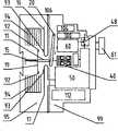
图1是本发明具有控制和保护功能的开关电器的一个实施例的原理示意图;Fig. 1 is the schematic diagram of the principle of an embodiment of the switching device with control and protection functions of the present invention;
图2是图1的本发明开关电器实施例的上下两层结构的分解示意图;Fig. 2 is an exploded schematic diagram of the upper and lower two-layer structure of the switching device embodiment of the present invention of Fig. 1;
图3a是图1的本发明开关电器实施例的总体结构的示意图;Fig. 3 a is the schematic diagram of the overall structure of the switching device embodiment of the present invention of Fig. 1;
图3b是图3a的左侧视图;Figure 3b is a left side view of Figure 3a;
图4a是本发明具有控制和保护功能的开关电器的另一实施例的总体结构示意图;Fig. 4a is the overall structure schematic diagram of another embodiment of the switching device with control and protection functions of the present invention;
图4b是图4a的左侧视图;Fig. 4b is the left side view of Fig. 4a;
图5a是本发明具有控制和保护功能的开关电器的又一实施例的总体结构示意图;Fig. 5a is the overall structure schematic diagram of another embodiment of the switching device with control and protection functions of the present invention;
图5b是图5a的左侧视图。Figure 5b is a left side view of Figure 5a.
具体实施方式Detailed ways
下面结合附图所示的实施例,进一步说明本发明的具有控制和保护功能的开关电器。本发明不限于以下相对附图给出的对各具体实施例的描述。The switching device with control and protection functions of the present invention will be further described below in conjunction with the embodiments shown in the accompanying drawings. The invention is not limited to the following description of specific embodiments given with respect to the accompanying drawings.
如图1所示,本发明的具有控制和保护功能的开关电器,包括底座95和罩壳99构成的外壳。底座95内装有静触头93和动触头92。静触头93分别通过电源导体16、17与设置在底座95上的主电路电源端子106和主电路负载端子105相连。动触头92设置在接触桥19的两端,接触桥19的一侧与触头支持11固定连接且一侧与触头支持定位面相邻,另一侧与弹簧15的一端连接。弹簧15的另一端固定在底座95上,并为动触头92向静触头93闭合提供驱动力和接触力。所述的触头支持11受所述的传动装置20控制,在合闸状态时,传动装置20与触头支持11不接触,以使动触头92在弹簧15的弹力作用下与静触头93接触闭合,并在动、静触头之间形成稳定的接触力;在跳闸或分闸过程中,传动装置20始终与触头支持11接触,并驱使动触头92克服弹簧15的弹力作与静触头93分离的运动,从而使动、静触头断开。As shown in FIG. 1 , the switching device with control and protection functions of the present invention includes a housing composed of a
如图所示,罩壳99内装有电磁铁40、操作机构60、脱扣器50、磁通适配器52、开关48、电压变换电路80、电源导线101a和101b、连接导线102和103、传动装置20、辅助触头模块100和104以及通信模块或功能模块112及其接线端子110。这里,通信模块和功能模块只能二者选一,均用标号112代表。As shown in the figure, the
设置在罩壳99上的控制电源端子108直接通过电源导线101a和101b,并联连接在电磁铁40和电压变换电路80的输入端上,并通过电压变换电路80将控制电源电压转换为预定直流电压输出。控制电源端子108的电压可以是交流型,也可以是直流型。所述电压变换电路80的输出端分别通过连接导线102和103与磁通适配器52和处理电路53并联连接,分别为它们提供工作电压。在控制电源端子108与电磁铁40、磁通适配器52和电压变换电路80的供电线路中,还串联一个受操作机构60控制的开关48。只有当操作机构60合闸时,开关48才能接通,电源才可以向电磁铁40、磁通适配器52和处理电路53供电。电压变换电路80由桥式整流电路、降压或升压变换电路、稳压变换电路中的一种或几种构成,能够把控制电源端子108的电源电压(如AC24V、AC48V、AC72V、AC110V、AC127V、AC220V、AC230V、AC240V、DC24V、DC48V、DC72V、DC110V、DC125V、DC220V、DC250V)转换为预定直流电压,作为磁通适配器52、处理电路53的工作电压。The control
脱扣器50包括电流互感器55和处理电路53。电流互感器55能够在主电路发生如过载、短路等电气故障时,监测到过载/短路电流信号,处理电路53再对过载/短路电流信号进行分析处理后,向磁通适配器52输出跳闸指令,从而磁通适配器52驱动操作机构60跳闸,使动触头92从闭合位置转换到断开位置。The
本发明的一个重要发展在于,电磁铁40直接由控制电源端子108供电,供电的通/断受开关48控制,电压类型为交流型或直流型,由客户根据所需电源电压选取。操作机构60位于电磁铁40的上方或侧面,它不仅受人为控制和脱扣器50的磁通适配器52的控制,而且还可以控制开关48。本发明的具有控制和保护功能的开关电器不工作时或者控制电源端子108的电压为0时,操作机构60和电磁铁40都压住传动装置20,使开关48断开,保持动触头92处于断开位置。An important development of the present invention is that the
当操作手动操作钮61使操作机构60合闸时,开关48接通,使控制电源端子108向电磁铁40供电,电磁铁40通电后吸合,传动装置20受其复位力和弹簧15的作用力共同驱动向上转动,触头支持11向上移动,使动触头92从断开位置转换到闭合位置,主电路接通。When operating the
控制电源端子108只要出现人为断电、或者操作机构60人为分闸、或者脱扣器50发出跳闸指令使操作机构60跳闸中的一种或多种情况时,动触头92都会从闭合位置转换到断开位置,使主电路断开。具体动作过程是,当控制电源端子108人为断电,电磁铁40断电释放,电磁铁40压住并驱使传动装置20向下转动,触头支持11向下移动,使动触头92从闭合位置转换到断开位置,主电路断开。当人为操作手动操作钮61使操作机构60分闸时,开关48断开,电磁铁40断电释放,操作机构60和电磁铁40压住并驱使传动装置20向下转动,触头支持11向下移动,使动触头92从闭合位置转换到断开位置,主电路断开。As long as the control
当操作手动操作钮61使操作机构60合闸,并使动触头92处于闭合位置时,电压变换电路80向脱扣器50中的处理电路53供电,电流互感器55时时监测电路的运行状况,把监测到的故障信号传送给处理电路53进行分析处理,并在过载/短路电流出现时,处理电路53向磁通适配器52发出跳闸指令,驱动操作机构60动作,然后使开关48断开,电磁铁40断电释放,操作机构60和电磁铁40压住传动装置20并使其向下转动,触头支持11向下移动,使动触头92从闭合位置转换到断开位置,主电路断开。When the
在分闸或跳闸过程中,操作机构60的动作直接作用到传动装置20上,由于操作机构动作的起动速度要比电磁铁40动作的起动速度快得多,所以本发明的具有控制和保护功能的开关电器的开断性能很强,它不仅具有断路器所具备的控制和保护功能,而且还具有断路器所具备的快速分断能力。In the process of opening or tripping, the action of the
在合闸过程中,动触头92向静触头93闭合所需的作用力由弹簧15提供,因此,本发明的具有控制和保护功能的开关电器的合闸速度不仅快捷、而且还很稳定,所以它还具有了接触器所具备的可频繁操作的性能。During the closing process, the active force required for the closing of the moving
图2、3a示出了本发明具有控制和保护功能的开关电器的上下两层形式的总体结构。本发明的开关电器总体分为上下两层结构。下层为带有塑壳18的底座组件951,上层为罩壳组件991。脱扣器50、辅助触头模块104和100、通信模块或功能模块112设计成可互换型插拔式独立模块,便于用户根据需求更换。脱扣器50设计成多个电流段可互换型插拔式独立模块,具有断相保护、相不平衡保护和过载/短路保护等功能。脱扣器50的额定电流大小由客户根据所用负载的额定电流(或功率)选取,在产品使用现场,还可以设置过载和短路保护整定倍数、脱扣等级(如10A、10、20、30),负载电机极数(如三相或单相)等。辅助触头模块104和100由常开和/或常闭辅助触头组、报警触头组、手柄指示触头组的一种或几种构成。通信模块或功能模块112具有遥测、遥信、遥调、遥控“四遥”功能,适用于ModBus、Profibus、DeviceNet等通讯协议。通信模块或功能模块112设计成多个具有不同功能的模块,分别具有故障区分、负载指示、手动和自动复位、热过载报警功能,由脱扣器50提供工作电源。操作机构60可由手动操作钮61直接手动合闸或分闸,手动操作钮61可以是旋钮,也可以是按钮、旋转手柄或拔动手柄,或者类似能够使操作机构合闸或分闸的手动操作装置。Figures 2 and 3a show the overall structure of the switching device with control and protection functions in the form of upper and lower layers of the present invention. The switching device of the present invention is generally divided into upper and lower two-layer structures. The lower layer is the
图2、3a和3b示出了本发明具有控制和保护功能的开关电器内部结构和主要部件的布局。本发明的开关电器总体设计成上下两层结构,下层为底座组件951,上层为罩壳组件991。底座组件951由设置在底座95内的静触头93、动触头92、灭弧室94、触头支持11、提供触头闭合所需的驱动力和接触力的弹簧15和塑壳18组成。罩壳组件991由设置在罩壳99内的电磁铁40、脱扣器50、操作机构60、开关48、传动装置20、辅助触头模块100和104、通信模块或功能模块112组成。电磁铁40和操作机构60共同相互协调作用在传动装置20上,控制着动、静触头的接通与断开。操作机构60还控制着电磁铁40,只有先手动合闸操作机构60,电磁铁40才可以通电工作;但会受脱扣器50控制,当脱扣器50监测到主电路有过载、短路等电气故障时,会驱动操作机构60跳闸。Figures 2, 3a and 3b show the internal structure and the layout of the main components of the switching device with control and protection functions of the present invention. The switching device of the present invention is generally designed as an upper and lower two-layer structure, the lower layer is the
辅助触头模块104和100、通信模块或功能模块112设计成可互换型插拔式独立模块,直接装在上层罩壳组件991中。辅助触头模块104设在上层罩壳组件991最上面,辅助触头模块100设在辅助触头模块104的下面。辅助触头模块的指令端子109和107分别设在罩壳99上的位于主电路电源端子106下方的第二层和/或第三层台阶上。控制电源端子108设在罩壳99上的位于辅助触头模块的指令端子109和107右面或左面第二层和/或第三层台阶上。主电路电源端子106设在底座95最上面的第一层台阶上,主电路负载端子105设在底座95最下面的第一层台阶上。主电路电源端子106也可设在罩壳99最前端,主电路负载端子105也可设在罩壳99最下端。主电路电源端子106和主电路负载端子105、控制电源端子108、辅助触头模块的指令端子109和107以台阶状布置成上中下三层,便于客户区别与接线。The
通信模块或功能模块112与脱扣器50相联,设在罩壳99内,位于脱扣器50下端的一个公用空腔内,为可互换型插拔式独立模块。The communication module or
图4a、4b和图5a、5b分别示出了具有不同的操作机构与电磁铁位置的本发明的另外两种不同的实施例。如图4a、4b所示的实施例,操作机构60设在辅助触头模块组100和104的下面,操作机构60的下面是电磁铁40,再下面是脱扣器50,最下面是通信模块或功能模块112。电磁铁40大致处在中间位置,操作机构60、电磁铁40和脱扣器50成“三”字形排列。图5a、5b示出的实施例,操作机构60和电磁铁40平行放置,一起设在辅助触头模块组100和104及控制电源端子108下面,脱扣器50设置在操作机构60和电磁铁40的下面,最后是通信模块或功能模块112,脱扣器50、电磁铁40和操作机构60成倒“品”字形排列。Figures 4a, 4b and Figures 5a, 5b respectively show two other different embodiments of the present invention with different operating mechanisms and electromagnet positions. In the embodiment shown in Figures 4a and 4b, the
本发明的开关电器结构紧凑、体积小、寿命长,是一种既可频繁操作又具有高开断性能的集控制和过载、短路保护等多种功能于一体的开关电器。The switching device of the present invention is compact in structure, small in size and long in service life. It is a switching device that can be operated frequently and has high breaking performance and integrates multiple functions such as control, overload and short circuit protection.
Claims (14)
Priority Applications (1)
| Application Number | Priority Date | Filing Date | Title |
|---|---|---|---|
| CN2008100043552ACN101494143B (en) | 2008-01-23 | 2008-01-23 | Switch electric appliance with control and protection function |
Applications Claiming Priority (1)
| Application Number | Priority Date | Filing Date | Title |
|---|---|---|---|
| CN2008100043552ACN101494143B (en) | 2008-01-23 | 2008-01-23 | Switch electric appliance with control and protection function |
Publications (2)
| Publication Number | Publication Date |
|---|---|
| CN101494143A CN101494143A (en) | 2009-07-29 |
| CN101494143Btrue CN101494143B (en) | 2011-09-07 |
Family
ID=40924671
Family Applications (1)
| Application Number | Title | Priority Date | Filing Date |
|---|---|---|---|
| CN2008100043552AActiveCN101494143B (en) | 2008-01-23 | 2008-01-23 | Switch electric appliance with control and protection function |
Country Status (1)
| Country | Link |
|---|---|
| CN (1) | CN101494143B (en) |
Families Citing this family (12)
| Publication number | Priority date | Publication date | Assignee | Title |
|---|---|---|---|---|
| CN103177884B (en) | 2011-12-26 | 2016-09-14 | 上海电科电器科技有限公司 | The structure of contact terminal of low-voltage electrical apparatus |
| CN103177905B (en)* | 2011-12-26 | 2015-04-29 | 上海电科电器科技有限公司 | Control and protection device of low-voltage apparatus |
| EP2800220B1 (en)* | 2011-12-26 | 2016-10-26 | Seari Electric Technology Co., Ltd. | Control and protection device for low-voltage electrical appliance |
| CN103324243A (en)* | 2012-03-23 | 2013-09-25 | 苏州工业园区新宏博通讯科技有限公司 | Three-phase electric protector |
| FR3007888B1 (en)* | 2013-06-27 | 2015-07-17 | Schneider Electric Ind Sas | ELECTRICAL CONTACTOR AND METHOD FOR CONTROLLING SUCH A CONTACTOR |
| CN106786346A (en)* | 2017-02-10 | 2017-05-31 | 黑龙江恒讯科技有限公司 | A kind of IP-based miniature circuit breaker |
| CN108817014A (en)* | 2018-04-23 | 2018-11-16 | 连超强 | A kind of power construction safety cap cleaning device |
| CN111668744A (en)* | 2020-06-02 | 2020-09-15 | 上海电气集团股份有限公司 | Low-voltage switch unit for low-voltage switch cabinet |
| CN213025987U (en)* | 2020-07-17 | 2021-04-20 | 浙江正泰电器股份有限公司 | breaker |
| CN112382541B (en)* | 2020-08-26 | 2025-09-23 | 中国电力科学研究院有限公司 | An intelligent molded case circuit breaker with broadband power line carrier communication function |
| CN114388308A (en)* | 2020-10-21 | 2022-04-22 | 天津首瑞智能电气有限公司 | Circuit breaker |
| CN113418559A (en)* | 2021-06-22 | 2021-09-21 | 湖南第一师范学院 | Power load monitoring device |
Citations (4)
| Publication number | Priority date | Publication date | Assignee | Title |
|---|---|---|---|---|
| CN1397972A (en)* | 2001-07-18 | 2003-02-19 | 施耐德电器工业公司 | Switch of multipolar contactor-breaker |
| US7023305B2 (en)* | 2001-11-16 | 2006-04-04 | Schneider Electric Industries Sas | Control and protection module of a switch device |
| CN1954400A (en)* | 2004-05-14 | 2007-04-25 | 西门子公司 | Circuit-breaker and corresponding method for adjusting the same |
| CN201146161Y (en)* | 2008-01-23 | 2008-11-05 | 浙江正泰电器股份有限公司 | Switch electric apparatus with functions of control and protection |
- 2008
- 2008-01-23CNCN2008100043552Apatent/CN101494143B/enactiveActive
Patent Citations (4)
| Publication number | Priority date | Publication date | Assignee | Title |
|---|---|---|---|---|
| CN1397972A (en)* | 2001-07-18 | 2003-02-19 | 施耐德电器工业公司 | Switch of multipolar contactor-breaker |
| US7023305B2 (en)* | 2001-11-16 | 2006-04-04 | Schneider Electric Industries Sas | Control and protection module of a switch device |
| CN1954400A (en)* | 2004-05-14 | 2007-04-25 | 西门子公司 | Circuit-breaker and corresponding method for adjusting the same |
| CN201146161Y (en)* | 2008-01-23 | 2008-11-05 | 浙江正泰电器股份有限公司 | Switch electric apparatus with functions of control and protection |
Also Published As
| Publication number | Publication date |
|---|---|
| CN101494143A (en) | 2009-07-29 |
Similar Documents
| Publication | Publication Date | Title |
|---|---|---|
| CN101494143B (en) | Switch electric appliance with control and protection function | |
| CN200993948Y (en) | Safety earth fault circuit breaker | |
| CN103177905B (en) | Control and protection device of low-voltage apparatus | |
| CN107910232B (en) | An intelligent leakage protection switch | |
| WO2013097696A1 (en) | Control and protection device for low-voltage electrical appliance | |
| CN101114557A (en) | Safety circuit breaker | |
| CN109904041A (en) | A two-pole circuit breaker with L-pole and N-pole controlled by information | |
| CN201146161Y (en) | Switch electric apparatus with functions of control and protection | |
| CN108061838B (en) | Electric leakage test method for ensuring normal electricity consumption of user | |
| CN216980475U (en) | Intelligent low-voltage circuit breaker | |
| CN206977148U (en) | It is a kind of that civil power and the circuit of oil machine switching are controlled using PLC and touch-screen | |
| CN106059055A (en) | Control circuit of automatic changeover switch device | |
| CN108598922A (en) | Segmented threephase load phasing switch cabinet | |
| CN201298670Y (en) | Enclosed double-bus bar switch device | |
| CN111524758A (en) | Remote negative control locking and opening device of circuit breaker | |
| CN202423185U (en) | Control and protecting switch electric appliance | |
| CN102903577B (en) | Contactor with switching mechanism | |
| CN207651433U (en) | A kind of Intelligent leakage protection switch | |
| CN209544874U (en) | Intelligent power supply and distribution system | |
| CN102412104A (en) | Control and protection switch electric appliance | |
| CN112700981A (en) | Backup brake separating device of switch cabinet and control method thereof | |
| CN111710573A (en) | a fuse layout | |
| CN215934443U (en) | Three-phase inconsistent protection circuit of circuit breaker | |
| CN210867267U (en) | Medium-voltage automatic change-over switch equipment | |
| CN205319049U (en) | Automatic transfer switch |
Legal Events
| Date | Code | Title | Description |
|---|---|---|---|
| C06 | Publication | ||
| PB01 | Publication | ||
| C10 | Entry into substantive examination | ||
| SE01 | Entry into force of request for substantive examination | ||
| C14 | Grant of patent or utility model | ||
| GR01 | Patent grant |