CN101493543A - Ring shaped light guide and electronic equipment with the same - Google Patents
Ring shaped light guide and electronic equipment with the sameDownload PDFInfo
- Publication number
- CN101493543A CN101493543ACNA2009100026138ACN200910002613ACN101493543ACN 101493543 ACN101493543 ACN 101493543ACN A2009100026138 ACNA2009100026138 ACN A2009100026138ACN 200910002613 ACN200910002613 ACN 200910002613ACN 101493543 ACN101493543 ACN 101493543A
- Authority
- CN
- China
- Prior art keywords
- light guide
- mentioned
- light
- incident
- ring shaped
- Prior art date
- Legal status (The legal status is an assumption and is not a legal conclusion. Google has not performed a legal analysis and makes no representation as to the accuracy of the status listed.)
- Granted
Links
Images


Landscapes
- Non-Portable Lighting Devices Or Systems Thereof (AREA)
- Switch Cases, Indication, And Locking (AREA)
- Push-Button Switches (AREA)
- Led Device Packages (AREA)
Abstract
Translated fromChinese
Description
Translated fromChinese技术领域technical field
本发明涉及一种在示出电子设备的动作状态的显示装置等中使用、用于环状发光的环状光导件及具有该光导件的电子设备。The present invention relates to a ring-shaped light guide for use in a display device or the like showing an operating state of an electronic device for ring-shaped light emission, and an electronic device having the light guide.
背景技术Background technique
在录音装置、个人计算机、移动电话等电子设备中设置有各种显示装置,以显示电子设备的动作状态等。作为该显示装置的一例,例如包括以包围按压按钮的方式环状发光的装置。在该显示装置中,为了引导来自发光体的光,使用环状的光导件。Various display devices are installed in electronic equipment such as recording devices, personal computers, and mobile phones to display the operating status of the electronic equipment and the like. An example of such a display device includes, for example, a device that emits light in a ring so as to surround a push button. In this display device, an annular light guide is used to guide the light from the light emitter.
作为现有的光导件,如专利文献1所示公知有如下装置:在环状的光导件上设置向其切线方向延伸的2个入光部,在这些入光部配置光源。从各个入光部入射的光在光导件内反射,同时逆向进入大致整周,在其间从作为光导件的上表面的环状的射出端射出,产生光环。As a conventional light guide, as disclosed in Patent Document 1, there is known a device in which two light incident portions extending tangentially are provided on a ring-shaped light guide, and light sources are arranged in these light incident portions. The light incident from each light incident part is reflected in the light guide, and enters substantially the entire circumference in the reverse direction, and is emitted from the ring-shaped output end serving as the upper surface of the light guide to generate a halo.
此外,在专利文献2中记载了如下光导件:在环状的主体上连接大致直线状延伸的光导部,整体呈板状。主体由于内周的中心和外周的中心偏离而呈偏心的环状。在光导部的端面上配置有一个光源。In addition, Patent Document 2 describes a light guide in which a light guide portion extending substantially linearly is connected to a ring-shaped main body, and has a plate shape as a whole. The main body has an eccentric annular shape due to the offset of the center of the inner circumference and the center of the outer circumference. A light source is disposed on the end face of the light guide.
专利文献1:JP特许第3770154号Patent Document 1: JP Patent No. 3770154
专利文献2:JP特开2006-179379号公报Patent Document 2: JP Unexamined Publication No. 2006-179379
为了降低成本而使用一个或两个光源,但此时也需要使光环的各部保持均匀的亮度。在上述专利文献1的光导件中,为了形成均匀亮度的光环,在光导件内混入了漫反射物质,或以预定的间距形成越远离光源越长的倾斜的狭缝,通过各个狭缝将在圆周方向进入的光向射出端反射。但是,光的强度与距离的乘方成反比地衰减,因此仅通过混入漫反射物质难以获得均匀的照明。此外在形成狭缝的情况下,由于多个狭缝并排,因此如果经过几个狭缝反射,则经过狭缝部分的光的强度会急剧下降。因此还是难以获得均匀的照明。In order to reduce costs, one or two light sources are used, but at this time it is also necessary to maintain uniform brightness in each part of the light ring. In the light guide of the above-mentioned Patent Document 1, in order to form a halo of uniform brightness, a diffuse reflective material is mixed in the light guide, or inclined slits are formed at predetermined intervals and become longer as they are farther away from the light source. The light entering in the circumferential direction is reflected toward the exit end. However, the intensity of light attenuates inversely proportional to the power of the distance, so it is difficult to obtain uniform illumination only by mixing diffuse reflective substances. In addition, when forming slits, since a plurality of slits are arranged side by side, the intensity of the light passing through the slit portion will drop sharply if it is reflected by several slits. It is therefore still difficult to obtain uniform illumination.
此外在专利文献2中使用偏心的板状的环,到光源的距离越长,环的宽度越窄,光密度越高。但是在该专利文献2中,需要使光导部附近的宽度非常大,因此需要很大的设置空间,在配置上受到制约。In addition, in Patent Document 2, an eccentric plate-shaped ring is used, and the longer the distance to the light source, the narrower the ring width and the higher the optical density. However, in this patent document 2, since the width near the light guide part needs to be made very large, a large installation space is required, and arrangement|positioning is restricted.
发明内容Contents of the invention
本发明为了解决上述问题,其目的在于提供一种不需要较大的设置空间的环状光导件及具有该光导件的电子设备。In order to solve the above-mentioned problems, the present invention aims to provide an annular light guide that does not require a large installation space, and an electronic device including the light guide.
为了实现上述目的,本发明的环状光导件,将来自发光体的光向形成于外装面板的显示窗引导,其特征在于,包括:入射部,与上述发光体相对;环状的光导部,引导从上述入射部入射的光;射出端,使经过了上述光导部的光从上述显示窗射出;和射出用反射面,在上述光导部的整周形成,使在上述光导部内部引导的光朝向上述射出端反射,并且与到上述入射部的距离相对应地扩大宽度。另外,作为构成环状光导件的材料,包括丙烯、AS(丙烯腈苯乙烯)等。In order to achieve the above object, the ring-shaped light guide of the present invention guides the light from the illuminant to the display window formed on the exterior panel, and is characterized in that it includes: an incident part, opposite to the above-mentioned illuminant; an annular light guide part, guide the light incident from the above-mentioned incident part; emit the light passing through the above-mentioned light-guiding part from the above-mentioned display window; It is reflected toward the above-mentioned emission end, and the width is enlarged according to the distance from the above-mentioned incident portion. In addition, as a material constituting the annular light guide, acrylic, AS (acrylonitrile styrene), and the like are included.
此外优选的是,上述射出用反射面通过增大倾斜角度来扩大宽度。In addition, it is preferable that the width of the reflection surface for emission is increased by increasing the inclination angle.
进而优选的是,向上述入射部入射来自上述发光体的光,该发光体设置在上述显示窗的外侧,向与来自上述显示窗的射出方向大致平行的方向发光,在上述光导部中形成有使入射到上述入射部的光朝向上述射出用反射面反射的光导用反射面。Further preferably, light from the illuminant is incident on the incident portion, the illuminant is disposed outside the display window, emits light in a direction approximately parallel to the direction of emission from the display window, and a light guide is formed in the light guide portion. A reflective surface for a light guide that reflects light incident on the incident portion toward the reflective surface for emission.
此外优选的是,在上述光导部中形成有用于收纳按压按钮的按钮用开口。Furthermore, it is preferable that an opening for a button for accommodating a push button is formed in the light guide portion.
进而本发明的电子设备,其特征在于,包括:具有开口的外装面板;嵌合到上述开口内的上述环状光导件;和能够按压地收纳在上述环状光导件内的按压按钮。另外,作为上述电子设备,包括录音机、个人计算机、CD播放器、DVD播放器等。Furthermore, the electronic device of the present invention is characterized by comprising: an exterior panel having an opening; the ring-shaped light guide fitted into the opening; and a push button housed in the ring-shaped light guide so as to be depressible. Moreover, as said electronic equipment, a recorder, a personal computer, a CD player, a DVD player, etc. are included.
根据本发明的环状光导件,形成于光导部并向射出端反射的射出用反射面的宽度,与到入射部的距离相对应地扩大,因此可以在整周使来自显示窗的射出量均匀。此外在狭窄的设置中间中也可以设置。According to the ring-shaped light guide of the present invention, the width of the reflection surface for emission formed on the light guide portion and reflected toward the emission end is enlarged corresponding to the distance from the entrance portion, so that the amount of emission from the display window can be made uniform over the entire circumference. . In addition, it can also be installed in the middle of a narrow setting.
此外,射出用反射面通过增大倾斜角度来扩大宽度,因此光导部在直径方向上的厚度不变。In addition, since the width of the reflection surface for emission is increased by increasing the inclination angle, the thickness of the light guide portion in the radial direction does not change.
附图说明Description of drawings
图1是表示实施了本发明的便携式录音机的平面图。Fig. 1 is a plan view showing a portable recorder embodying the present invention.
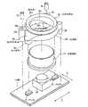
图2是表示录音/录音暂时停止按钮、左LED芯片、右LED芯片和环状光导件的分解透视图。2 is an exploded perspective view showing a recording/recording temporary stop button, a left LED chip, a right LED chip, and a ring-shaped light guide.
图3(A)是图1的A-A分解剖视图,(B)是组装状态的A-A剖视图。Fig. 3(A) is an exploded cross-sectional view of A-A in Fig. 1, and (B) is a cross-sectional view of A-A in an assembled state.
图4(A)是图1的B-B剖视图,(B)是C-C剖视图,(C)是D-D剖视图。Fig. 4(A) is a B-B sectional view of Fig. 1 , (B) is a C-C sectional view, and (C) is a D-D sectional view.
具体实施方式Detailed ways
如图1所示,便携式录音机2包括主体盒3和麦克风4。麦克风4设置有两个。麦克风4中,用于将收集到的声音变换为电信号的变换器5被收纳在麦克盒6中。As shown in FIG. 1 , the portable recorder 2 includes a
在主体盒3的内部设置有基板7,在基板7上安装有用于控制便携式录音机2的驱动的CPU 8。The inside of the
在主体盒3的内部可装卸地收纳有SD卡9,来自麦克风4的电信号作为声音数据记录在SD卡9中。An
在主体盒3上设置有LCD 11、录音/录音暂时停止按钮(以下称为录音按钮)12、重放/重放暂时停止按钮(以下称为重放按钮)13、停止按钮14、菜单按钮15、轻推转盘(Jog Dial)16、输出端子17。另外,各按钮12~15由按压方式的按钮构成。
按压重放按钮13后,进行SD卡9内记录的声音数据的重放控制,在重放控制中按压重放按钮13后,进行重放暂时停止控制。重放的录音数据被传输到输出端子17。如果在输出端子17安装扬声器,则可以听到重放的声音。When the
按压菜单按钮15后,在LCD 11上显示用于进行各种设定的设定画面。在LCD 11上除了显示设定画面之外,还显示用于选择重放的声音数据的选择画面。操作轻推转盘16进行设定及选择。此外在主体盒3上设置有快进按钮、倒退按钮等各种按钮。When the
如图2及图3所示,在基板7上安装有左LED芯片21及右LED芯片22。各LED芯片21、22设置在显示窗3a的外侧,向与来自显示窗3a的射出方向大致平行的方向发光。As shown in FIGS. 2 and 3 , the
各LED芯片21、22可变化为点灯状态、闪烁状态、熄灯状态,通过CPU 8单独地控制。作为这些LED芯片21、22,可以使用发出白色光的,也可以使用发出3原色光中的一个的。Each
在基板7上安装有录音开关23。按压录音按钮12后,录音开关23接通,向CPU 8输入接通信号。CPU 8从录音开关23输入接通信号后,进行开始麦克风4的录音的控制,如果在录音控制中输入接通信号,则进行录音暂时停止控制。A
CPU 8在录音控制中使各LED芯片21、22点灯,在录音暂时停止控制中使各LED芯片21、22闪烁。The
在主体盒3上形成有显示窗3a,在该显示窗3a中插入环状光导件25。在主体盒3的内面设置有两个用于安装环状光导件25的安装凸台3b。A
环状光导件25包括左入射部25a、右入射部25b、光导部25c,通过透过光的透明树脂(例如丙烯)成形。左入射部25a与左LED芯片21相对,右入射部25b与右LED芯片22相对。在光导部25c的上表面设置射出端25d,射出端25d与主体盒3的显示窗3a嵌合。The annular
光导部25c形成为环状,对向各入射部25a、25b入射的光进行反射的同时,沿着环状的形状在圆周方向上导光。在光导部25c的内周面上形成有射出用反射面25e,以使在光导部25c的内部在圆周方向上引导的光朝向射出端25d反射。入射到射出端25d的光从显示窗3a射出。The
在光导部25c的外周面上形成有光导用反射面25f。光导用反射面25f形成在各入射部25a、25b的上方,对入射到各入射部25a、25b的光进行反射。形成有各入射部25a、25b的部分的射出用反射面25e的宽度比光导用反射面25f的宽度窄,因此由光导用反射面25f反射的光中仅一部分光入射到形成有各入射部25a、25b的部分的射出用反射面25e上。由光导用反射面25f反射的光中、没有入射到形成有各入射部25a、25b的部分的射出用反射面25e上的光,在光导部25c的内部在圆周方向上导光。25 f of reflection surfaces for light guides are formed in the outer peripheral surface of the
在光导部25c上设置:形成有安装凹部25g的安装凸台25h、和定位凸台25i。安装凸台25h设置两个,在各自的安装凹部25g中插入主体盒3的安装凸台3b。The
在光导部25c上形成有开口25j。将录音按钮12插入到开口25j中后,录音按钮12可按压地收纳在环状光导件25内。An
如图3及图4所示,射出用反射面25e被形成为,如果到各入射部25a、25b的距离变长(图4(A)→图4(B)→图4(C)),则倾斜角度变大,其宽度变大。更详细地说,射出用反射面25e被形成为,随着从各入射部25a、25b离开,倾斜角度变陡,射出用反射面25e的面积变大。另外,图3是图1的A-A剖视图,图4(A)是B-B剖视图,图4(B)是C-C剖视图,图4(C)是D-D剖视图。另外图3(B)、图4(A)~(C)在环状光导件25处没有画阴影。As shown in Fig. 3 and Fig. 4, the
如图2及图3所示,将环状光导件25安装到主体盒3上时,将安装凸台3b插入到安装凹部25g中。将安装凸台3b插入到安装凹部25g中后,环状光导件25在上下方向(E方向)及左右方向(F方向)被定位,射出端25d嵌合到主体盒3的显示窗3a中。并且,在开口25j中插入录音按钮12。As shown in FIGS. 2 and 3 , when mounting the annular
如图4(A)所示,将基板7安装到主体盒3上后,安装凸台25h及定位凸台25i与基板7抵接,环状光导件25在前后方向(图4中的上下方向)被定位。As shown in FIG. 4(A), after the
接下来说明便携式录音机2的作用。录音按钮12被按压后,从录音开关23向CPU 8输入接通信号。CPU 8响应接通信号被输入,开始麦克风4的录音,并且使左LED芯片21及右LED芯片22点灯。Next, the operation of the portable recorder 2 will be described. After the
如图3(B)所示,从各LED芯片21、22入射到各入射部25a、25b的光被光导用反射面25f反射。As shown in FIG. 3(B), the light incident from each
被光导用反射面25f反射的光中仅一部分光入射到形成有各入射部25a、25b的部分的射出用反射面25e上。因此,从形成有各入射部25a、25b的部分的射出端25d射出的光量,与来自各LED芯片21、22的光量相比减少。被光导用反射面25f反射的光中、没有入射到形成有各入射部25a、25b的部分的射出用反射面25e上的光,在光导部25c的内部在圆周方向上被导光。Of the light reflected by the
如图4(A)~(C)所示,在光导部25的内部在圆周方向上引导的光,被射出用反射面25e朝向射出端25d反射。并且从射出端25d射出的光从显示窗3a射出。As shown in FIGS. 4(A) to (C), the light guided in the circumferential direction inside the
射出用反射面25e的宽度,到各入射部25a、25b的距离越长(图4(A)→图4(B)→图4(C))则越大。在本实施方式中,从各入射部25a、25b离开最远的图4(C)的部分,即图1中的D-D剖面的部分的射出用反射面25e,倾斜角度最大,宽度也最大。The width of the
射出用反射面25e的宽度变大时,入射到射出用反射面25e的光量增加,因此射出用反射面25e的反射量增加。从而,在到各入射部25a、25b的距离变长、在光导部25c的内部在圆周方向上引导的光的强度衰减的部分,也可以抑制从射出端25d射出的光量的减少。通过使射出用反射面25e的形状为适当的形状,可以使从射出端25d射出的光量在整周均匀。When the width of the
此外,从射出端25d射出的光量均匀时,与形成有各入射部25a、25b的部分的射出端25d的光量一致。在本实施方式中,使该部分的射出用反射面25e的倾斜角度最小,使其宽度最窄,从而从射出端25d射出的光量与从各LED芯片21、22入射的光量相比减少,因此可以容易地进行均匀化。In addition, when the amount of light emitted from the
另外在上述实施方式中,通过增大倾斜角度来扩大射出用反射面25e的宽度,但也可以不改变倾斜角度,通过增加光导部25c在直径方向上的厚度来扩大宽度。In the above embodiment, the width of the
此外,使来自LED芯片的光以与基板7平行的朝向入射到环状光导件25时,也可以实施本发明。此时,可以不设置光导用反射面25f。In addition, the present invention can also be implemented when the light from the LED chip is made to enter the ring-shaped
进而,LED芯片的个数也可以为1个或3个。对应于其个数,射出用反射面25e的形状也改变。Furthermore, the number of LED chips may be one or three. The shape of the
Claims (5)
Applications Claiming Priority (3)
| Application Number | Priority Date | Filing Date | Title |
|---|---|---|---|
| JP2008-008280 | 2008-01-17 | ||
| JP2008008280 | 2008-01-17 | ||
| JP2008008280AJP5120548B2 (en) | 2008-01-17 | 2008-01-17 | Ring-shaped light guide and electronic device equipped with the same |
Publications (2)
| Publication Number | Publication Date |
|---|---|
| CN101493543Atrue CN101493543A (en) | 2009-07-29 |
| CN101493543B CN101493543B (en) | 2012-02-01 |
Family
ID=40924228
Family Applications (1)
| Application Number | Title | Priority Date | Filing Date |
|---|---|---|---|
| CN2009100026138AExpired - Fee RelatedCN101493543B (en) | 2008-01-17 | 2009-01-09 | Annular light guide and electronic device with same |
Country Status (2)
| Country | Link |
|---|---|
| JP (1) | JP5120548B2 (en) |
| CN (1) | CN101493543B (en) |
Cited By (3)
| Publication number | Priority date | Publication date | Assignee | Title |
|---|---|---|---|---|
| CN108444200A (en)* | 2018-05-22 | 2018-08-24 | 海信(山东)冰箱有限公司 | A kind of decoration lamp mounting structure and refrigerator |
| CN109564442A (en)* | 2016-06-30 | 2019-04-02 | 普瑞有限公司 | The component formed by electronic pixel matrix display and the revolving actuator with improved light guide |
| WO2020000210A1 (en)* | 2018-06-26 | 2020-01-02 | 深圳市大疆创新科技有限公司 | Indication device and battery assembly |
Families Citing this family (6)
| Publication number | Priority date | Publication date | Assignee | Title |
|---|---|---|---|---|
| US8490829B2 (en) | 2009-11-24 | 2013-07-23 | Pepsico, Inc. | Personalized beverage dispensing device |
| US8335592B2 (en) | 2009-11-24 | 2012-12-18 | Pepsico, Inc. | Beverage dispensing device |
| JP5606395B2 (en)* | 2011-05-30 | 2014-10-15 | 三菱電機株式会社 | In-vehicle information equipment |
| KR102203273B1 (en)* | 2014-06-17 | 2021-01-14 | 현대모비스 주식회사 | Lighting device for button of audio-visual system |
| JP2017134985A (en)* | 2016-01-27 | 2017-08-03 | 株式会社東海理化電機製作所 | Start switch device |
| JP6631298B2 (en)* | 2016-02-12 | 2020-01-15 | ティアック株式会社 | Lighting device and electronic equipment for operation unit |
Family Cites Families (5)
| Publication number | Priority date | Publication date | Assignee | Title |
|---|---|---|---|---|
| JPH04328702A (en)* | 1991-04-30 | 1992-11-17 | San Aroo Kk | Light guide body |
| JPH07168026A (en)* | 1993-12-15 | 1995-07-04 | Shimura Kaken Kogyo Kk | Light guiding plate and luminaire using it |
| CN2756950Y (en)* | 2004-11-06 | 2006-02-08 | 鸿富锦精密工业(深圳)有限公司 | Light conductive pipe |
| JP2006147498A (en)* | 2004-11-24 | 2006-06-08 | Konica Minolta Business Technologies Inc | Push button |
| JP4725384B2 (en)* | 2006-03-24 | 2011-07-13 | サクサ株式会社 | Pushbutton switch lighting structure |
- 2008
- 2008-01-17JPJP2008008280Apatent/JP5120548B2/ennot_activeExpired - Fee Related
- 2009
- 2009-01-09CNCN2009100026138Apatent/CN101493543B/ennot_activeExpired - Fee Related
Cited By (7)
| Publication number | Priority date | Publication date | Assignee | Title |
|---|---|---|---|---|
| CN109564442A (en)* | 2016-06-30 | 2019-04-02 | 普瑞有限公司 | The component formed by electronic pixel matrix display and the revolving actuator with improved light guide |
| EP3479187B1 (en)* | 2016-06-30 | 2021-03-03 | Preh GmbH | Arrangement of electric pixel matrix display and rotary actuator with improved light guide |
| US11235702B2 (en) | 2016-06-30 | 2022-02-01 | Preh Gmbh | Arrangement of electric pixel matrix display and rotary actuator with improved light guide |
| CN108444200A (en)* | 2018-05-22 | 2018-08-24 | 海信(山东)冰箱有限公司 | A kind of decoration lamp mounting structure and refrigerator |
| WO2020000210A1 (en)* | 2018-06-26 | 2020-01-02 | 深圳市大疆创新科技有限公司 | Indication device and battery assembly |
| CN110678918A (en)* | 2018-06-26 | 2020-01-10 | 深圳市大疆创新科技有限公司 | Indicating device and battery pack |
| CN110678918B (en)* | 2018-06-26 | 2022-06-24 | 深圳市大疆创新科技有限公司 | Indicating device and battery pack |
Also Published As
| Publication number | Publication date |
|---|---|
| JP2009170309A (en) | 2009-07-30 |
| JP5120548B2 (en) | 2013-01-16 |
| CN101493543B (en) | 2012-02-01 |
Similar Documents
| Publication | Publication Date | Title |
|---|---|---|
| CN101493543A (en) | Ring shaped light guide and electronic equipment with the same | |
| US9813820B2 (en) | Loudspeaker, electronic apparatus using same, and mobile apparatus | |
| JP4784527B2 (en) | Light guide fixture and light guide device | |
| JP5428079B2 (en) | Fluorescent light emitting device and projector | |
| CN107071631B (en) | LED light even light guide structure and intelligent sound box | |
| JP5534336B2 (en) | Light source unit and projector | |
| JP3753117B2 (en) | Electronic device and method of mounting the display device | |
| JP5060628B2 (en) | Electronics | |
| TW200907751A (en) | Electronic apparatus | |
| JP2010114010A (en) | Lighting structure of mobile apparatus | |
| JP4904829B2 (en) | Luminescent display structure | |
| JP2004356028A (en) | Push button switch device | |
| JP4848905B2 (en) | Illuminated pushbutton unit | |
| CN107852798B (en) | control device | |
| JP5594392B2 (en) | Light emitting device and input device | |
| JP4609247B2 (en) | Luminescent switch | |
| TWM323652U (en) | Electronic apparatus | |
| CN110266858B (en) | electronic device | |
| JP5610214B2 (en) | Game machine | |
| US20240427077A1 (en) | Display apparatus and electronic instrument | |
| JP6439308B2 (en) | Telephone and operation device accessories | |
| JP4902007B2 (en) | Television equipment, electronic equipment | |
| JP4365301B2 (en) | Backlight device, liquid crystal display device including the backlight device, and recording / reproducing device including the liquid crystal display device | |
| JP2009182677A (en) | Mobile device | |
| WO2010055941A1 (en) | Illuminated small-size electronic apparatus |
Legal Events
| Date | Code | Title | Description |
|---|---|---|---|
| C06 | Publication | ||
| PB01 | Publication | ||
| C10 | Entry into substantive examination | ||
| SE01 | Entry into force of request for substantive examination | ||
| C14 | Grant of patent or utility model | ||
| GR01 | Patent grant | ||
| CF01 | Termination of patent right due to non-payment of annual fee | ||
| CF01 | Termination of patent right due to non-payment of annual fee | Granted publication date:20120201 Termination date:20180109 |