CN101490341A - Wave energy converter - Google Patents
Wave energy converterDownload PDFInfo
- Publication number
- CN101490341A CN101490341ACNA2007800263683ACN200780026368ACN101490341ACN 101490341 ACN101490341 ACN 101490341ACN A2007800263683 ACNA2007800263683 ACN A2007800263683ACN 200780026368 ACN200780026368 ACN 200780026368ACN 101490341 ACN101490341 ACN 101490341A
- Authority
- CN
- China
- Prior art keywords
- energy
- mooring system
- wave energy
- equipment
- buoyancy
- Prior art date
- Legal status (The legal status is an assumption and is not a legal conclusion. Google has not performed a legal analysis and makes no representation as to the accuracy of the status listed.)
- Granted
Links
Images


Classifications
- E—FIXED CONSTRUCTIONS
- E02—HYDRAULIC ENGINEERING; FOUNDATIONS; SOIL SHIFTING
- E02B—HYDRAULIC ENGINEERING
- E02B9/00—Water-power plants; Layout, construction or equipment, methods of, or apparatus for, making same
- E02B9/08—Tide or wave power plants
- B—PERFORMING OPERATIONS; TRANSPORTING
- B63—SHIPS OR OTHER WATERBORNE VESSELS; RELATED EQUIPMENT
- B63B—SHIPS OR OTHER WATERBORNE VESSELS; EQUIPMENT FOR SHIPPING
- B63B35/00—Vessels or similar floating structures specially adapted for specific purposes and not otherwise provided for
- B63B35/44—Floating buildings, stores, drilling platforms, or workshops, e.g. carrying water-oil separating devices
- F—MECHANICAL ENGINEERING; LIGHTING; HEATING; WEAPONS; BLASTING
- F03—MACHINES OR ENGINES FOR LIQUIDS; WIND, SPRING, OR WEIGHT MOTORS; PRODUCING MECHANICAL POWER OR A REACTIVE PROPULSIVE THRUST, NOT OTHERWISE PROVIDED FOR
- F03B—MACHINES OR ENGINES FOR LIQUIDS
- F03B13/00—Adaptations of machines or engines for special use; Combinations of machines or engines with driving or driven apparatus; Power stations or aggregates
- F03B13/12—Adaptations of machines or engines for special use; Combinations of machines or engines with driving or driven apparatus; Power stations or aggregates characterised by using wave or tide energy
- F03B13/14—Adaptations of machines or engines for special use; Combinations of machines or engines with driving or driven apparatus; Power stations or aggregates characterised by using wave or tide energy using wave energy
- F03B13/16—Adaptations of machines or engines for special use; Combinations of machines or engines with driving or driven apparatus; Power stations or aggregates characterised by using wave or tide energy using wave energy using the relative movement between a wave-operated member, i.e. a "wom" and another member, i.e. a reaction member or "rem"
- F03B13/18—Adaptations of machines or engines for special use; Combinations of machines or engines with driving or driven apparatus; Power stations or aggregates characterised by using wave or tide energy using wave energy using the relative movement between a wave-operated member, i.e. a "wom" and another member, i.e. a reaction member or "rem" where the other member, i.e. rem is fixed, at least at one point, with respect to the sea bed or shore
- F03B13/1845—Adaptations of machines or engines for special use; Combinations of machines or engines with driving or driven apparatus; Power stations or aggregates characterised by using wave or tide energy using wave energy using the relative movement between a wave-operated member, i.e. a "wom" and another member, i.e. a reaction member or "rem" where the other member, i.e. rem is fixed, at least at one point, with respect to the sea bed or shore and the wom slides relative to the rem
- B—PERFORMING OPERATIONS; TRANSPORTING
- B63—SHIPS OR OTHER WATERBORNE VESSELS; RELATED EQUIPMENT
- B63B—SHIPS OR OTHER WATERBORNE VESSELS; EQUIPMENT FOR SHIPPING
- B63B35/00—Vessels or similar floating structures specially adapted for specific purposes and not otherwise provided for
- B63B35/44—Floating buildings, stores, drilling platforms, or workshops, e.g. carrying water-oil separating devices
- B63B2035/4433—Floating structures carrying electric power plants
- B63B2035/4466—Floating structures carrying electric power plants for converting water energy into electric energy, e.g. from tidal flows, waves or currents
- F—MECHANICAL ENGINEERING; LIGHTING; HEATING; WEAPONS; BLASTING
- F05—INDEXING SCHEMES RELATING TO ENGINES OR PUMPS IN VARIOUS SUBCLASSES OF CLASSES F01-F04
- F05B—INDEXING SCHEME RELATING TO WIND, SPRING, WEIGHT, INERTIA OR LIKE MOTORS, TO MACHINES OR ENGINES FOR LIQUIDS COVERED BY SUBCLASSES F03B, F03D AND F03G
- F05B2210/00—Working fluid
- F05B2210/18—Air and water being simultaneously used as working fluid
- F—MECHANICAL ENGINEERING; LIGHTING; HEATING; WEAPONS; BLASTING
- F05—INDEXING SCHEMES RELATING TO ENGINES OR PUMPS IN VARIOUS SUBCLASSES OF CLASSES F01-F04
- F05B—INDEXING SCHEME RELATING TO WIND, SPRING, WEIGHT, INERTIA OR LIKE MOTORS, TO MACHINES OR ENGINES FOR LIQUIDS COVERED BY SUBCLASSES F03B, F03D AND F03G
- F05B2220/00—Application
- F05B2220/70—Application in combination with
- F05B2220/706—Application in combination with an electrical generator
- F05B2220/707—Application in combination with an electrical generator of the linear type
- F—MECHANICAL ENGINEERING; LIGHTING; HEATING; WEAPONS; BLASTING
- F05—INDEXING SCHEMES RELATING TO ENGINES OR PUMPS IN VARIOUS SUBCLASSES OF CLASSES F01-F04
- F05B—INDEXING SCHEME RELATING TO WIND, SPRING, WEIGHT, INERTIA OR LIKE MOTORS, TO MACHINES OR ENGINES FOR LIQUIDS COVERED BY SUBCLASSES F03B, F03D AND F03G
- F05B2240/00—Components
- F05B2240/90—Mounting on supporting structures or systems
- F05B2240/91—Mounting on supporting structures or systems on a stationary structure
- F05B2240/917—Mounting on supporting structures or systems on a stationary structure attached to cables
- Y—GENERAL TAGGING OF NEW TECHNOLOGICAL DEVELOPMENTS; GENERAL TAGGING OF CROSS-SECTIONAL TECHNOLOGIES SPANNING OVER SEVERAL SECTIONS OF THE IPC; TECHNICAL SUBJECTS COVERED BY FORMER USPC CROSS-REFERENCE ART COLLECTIONS [XRACs] AND DIGESTS
- Y02—TECHNOLOGIES OR APPLICATIONS FOR MITIGATION OR ADAPTATION AGAINST CLIMATE CHANGE
- Y02E—REDUCTION OF GREENHOUSE GAS [GHG] EMISSIONS, RELATED TO ENERGY GENERATION, TRANSMISSION OR DISTRIBUTION
- Y02E10/00—Energy generation through renewable energy sources
- Y02E10/30—Energy from the sea, e.g. using wave energy or salinity gradient
Landscapes
- Engineering & Computer Science (AREA)
- Mechanical Engineering (AREA)
- General Engineering & Computer Science (AREA)
- Chemical & Material Sciences (AREA)
- Combustion & Propulsion (AREA)
- Civil Engineering (AREA)
- Structural Engineering (AREA)
- Architecture (AREA)
- Ocean & Marine Engineering (AREA)
- Other Liquid Machine Or Engine Such As Wave Power Use (AREA)
Abstract
Description
Translated fromChinese技术领域technical field
本发明涉及波能转换器,用于将海洋波能转换为电能,还特别但不排它地涉及依据浮力、流体动压力和振荡原理工作的波能转换器。更特别地,本发明还涉及用于波能转换器的张力锚泊系统。The present invention relates to wave energy converters for converting ocean wave energy into electrical energy, and particularly but not exclusively to wave energy converters operating on the principles of buoyancy, hydrodynamic pressure and oscillations. More particularly, the present invention also relates to tension mooring systems for wave energy converters.
背景技术Background technique
在三千年来,各地的人类越发关注如何生存。由于人类认识到矿物燃料是有限能源,对可再生清洁能源的探索变得更加急迫。全球变暖和气候变化把注意力聚焦到减少对矿物燃料的依靠的需求上。最有前景的可再生能源之一是波能。据估算,全世界波力(wave power)的潜在能量为2太瓦,这相当于全世界每年大约2000TWh的能源,足够全世界的电能需求。虽然利用波浪能量的愿望已存在数百年,但过去的尝试只获得了有限的成功。所取得的成功仅限于很小规模,实现了数十千瓦至数百千瓦的量级,而不是所需的数百兆瓦。For three thousand years, humans everywhere have become increasingly concerned with how to survive. As humans realize that fossil fuels are limited energy, the exploration of renewable clean energy has become more urgent. Global warming and climate change have focused attention on the need to reduce reliance on fossil fuels. One of the most promising renewable energy sources is wave energy. It is estimated that the potential energy of wave power in the world is 2 terawatts, which is equivalent to about 2000 TWh of energy per year in the world, which is enough for the world's electricity demand. While the desire to harness wave energy has existed for centuries, past attempts have met with limited success. The successes achieved have been on a very small scale, achieving tens to hundreds of kilowatts rather than the required hundreds of megawatts.
以往的主要困难之一是设计足够坚固(robust)以承受由海洋波浪产生的巨大力能的单元。在风暴条件下,波能是巨大的,造成了许多现有技术的基于陆地或基于海岸的系统的破坏。现有技术中典型的提取波能的手段是使用涡轮或液压系统。一些尝试是利用直接驱动的旋转发电机,以及直接驱动的线性发电机。然而,现有技术中最常规的能量提取单元是振荡水柱和液压联动旋转发电机(oscillating water columns and hydraulic linked rotarygenerators)。典型地,它们用于近岸(near-shore)、靠岸和岸上设施。这样的现有技术系统的另一主要缺点是需要靠近海岸,由于摩擦损失,海岸线波浪的能量损失很大,由此损失掉“深”水中的大部分波能。One of the major difficulties in the past has been designing cells that are robust enough to withstand the enormous forces and energies generated by ocean waves. Under storm conditions, wave energy is enormous, causing damage to many prior art land-based or coast-based systems. Typical means of extracting wave energy in the prior art is to use turbines or hydraulic systems. Some attempts have utilized direct drive rotary generators, as well as direct drive linear generators. However, the most conventional energy extraction units in the state of the art are oscillating water columns and hydraulic linked rotary generators. Typically, they are used in near-shore, onshore and onshore installations. Another major disadvantage of such prior art systems is the need to be close to the shore, the energy loss of shoreline waves is high due to frictional losses, thus losing most of the wave energy in "deep" water.
本发明以提供张力锚泊系统和波能转换器的视角得以开发,所述张力锚泊系统和波能转换器可用在近海或者离岸处以提取最大量的海洋波能。The present invention has been developed with a view to providing tension mooring systems and wave energy converters that can be used offshore or off shore to extract the maximum amount of ocean wave energy.
在本说明书中对现有技术的参考,仅用作说明的目的,而不应认为这种现有技术在澳大利亚或者其它地方是公知常识。References to prior art in this specification are made for illustrative purposes only and it is not to be taken as an admission that such prior art is common general knowledge, in Australia or elsewhere.
发明内容Contents of the invention
根据本发明的一个方面,设置有张力锚泊系统用于将海洋波能转换为更有用形式的设备,该设备包括具有浸没构件的结构,该浸没构件与该结构相连地设置在平均水位以下,该锚泊系统包括:According to one aspect of the invention, there is provided an apparatus for converting ocean wave energy into a more useful form provided with a tension mooring system, the apparatus comprising a structure having submerged members disposed below mean water level in connection with the structure, the apparatus The mooring system includes:
长的柔性构件,从配重机构延伸至抵衡机构,该索缆适合经由滑轮机构从浸没构件悬挂下来;和an elongated flexible member extending from the counterweight mechanism to the counterbalance mechanism, the cable being adapted to be suspended from the submerged member via the pulley mechanism; and
阻尼机构,用于向浸没构件的运动施加阻尼动作,该阻尼机构经由滑轮机构向长的柔性构件施加阻尼动作。A damping mechanism for imparting a damping action to the movement of the submerged member, the damping mechanism imparting a damping action to the elongate flexible member via the pulley mechanism.
优选地,抵衡机构包括具有质量块的容器,该质量块被设置为与所述容器相连,以提供经由长的柔性构件施加至浸没构件的抵衡力。Preferably, the counterbalancing mechanism comprises a container having a mass arranged in connection with said container to provide a counterbalancing force applied to the submerged member via the elongate flexible member.
优选地,抵衡机构包括具有质量块的可调的浮力容器,该质量块被设置为与所述容器相连,其中,抵衡机构的浮力可被调整以改变经由长的柔性构件施加至浸没构件的抵衡力。优选地,抵衡机构的浮力可通过经由空气软管向浮力容器泵送空气而被调整。Preferably, the counter-balancing mechanism comprises an adjustable buoyancy vessel having a mass arranged in connection with said vessel, wherein the buoyancy of the counter-balancing mechanism can be adjusted to vary the buoyancy force applied to the submerged member via the elongated flexible member. counterbalancing force. Preferably, the buoyancy of the counter-balance mechanism is adjustable by pumping air through the air hose to the buoyancy container.
有利地,锚泊系统进一步包括锚泊罐,并且该结构的浸没构件适于与锚泊罐对接。优选地,浸没构件通过锁定机构固定至锚泊罐。优选地,阻尼机构和滑轮机构容纳在锚泊罐中。Advantageously, the mooring system further comprises a mooring tank, and the submerged member of the structure is adapted to interface with the mooring tank. Preferably, the submerged member is secured to the mooring tank by a locking mechanism. Preferably, the damping mechanism and the pulley mechanism are housed in the mooring tank.
根据本发明的另一方面,提供了将海洋波能转换为更有用形式的设备,该设备包括:According to another aspect of the invention there is provided an apparatus for converting ocean wave energy into a more useful form comprising:
长的支承结构,被设计用来在平均水位上方延伸,具有与之相连地设置在平均水位以下的浸没构件,和使得支承结构以大致直立的取向漂浮在海洋中的浮力机构;an elongated support structure designed to extend above the mean water level, having associated therewith a submerged member disposed below the mean water level, and a buoyancy mechanism for allowing the support structure to float in the ocean in a generally upright orientation;
具有正浮力的漂浮构件,可滑动地安装在支承结构上以便可沿垂直方向运动;和a positively buoyant flotation member slidably mounted on the support structure for vertical movement; and
能量提取机构,被设置为与支承结构和漂浮构件相连,以使得当波浪运动在漂浮构件和支承结构之间引起适当的差速运动时,所述能量提取机构将传入的(incident)能量转换为更有用的形式。an energy extraction mechanism arranged in connection with the support structure and the buoyant structure such that when wave motion induces an appropriate differential motion between the buoyant structure and the support structure, the energy extraction mechanism converts incident energy into into a more useful form.
优选地,漂浮构件设置有滑行艇表面,该表面适于将波浪运动的水平分量转换为漂浮构件的垂直运动,由此增强漂浮构件的能量提取能力。典型地,漂浮构件具有包括前端和后端的长水平横截面,该前端适于面对正靠近的波浪的大致方向。优选地,所述前端变窄为尖端。优选地,所述滑行艇表面是多个大致平行的滑行艇表面中的一个,这些滑行艇表面大致垂直于并沿漂浮构件的相应第一和第二侧延伸。优选地,所述多个滑行艇表面从漂浮构件的前端向下倾斜到后端,其中,滑行艇表面迫使波浪中的水粒子向下,产生向上作用在滑行艇表面上的流体动力,所述流体动力增强了由于漂浮构件的正浮力而作用在漂浮构件上的向上力。Preferably, the floating member is provided with a planing surface adapted to convert a horizontal component of wave motion into a vertical movement of the floating member, thereby enhancing the energy extraction capability of the floating member. Typically, the buoyant member has a long horizontal cross-section comprising a front end adapted to face the general direction of an approaching wave and a rear end. Preferably, the front end narrows to a point. Preferably, said planing boat surface is one of a plurality of substantially parallel planing boat surfaces extending substantially perpendicular to and along respective first and second sides of the flotation member. Preferably, said plurality of planing boat surfaces slope downwardly from a front end to an aft end of the flotation member, wherein the planing boat surfaces force water particles in the waves downwards, generating hydrodynamic forces acting upwardly on the planing boat surfaces, said The hydrodynamic forces increase the upward force on the buoyant member due to the positive buoyancy of the buoyant member.
根据本发明的另一方面,在用于将海洋波能转换为可用能量的设备中设置有改进的漂浮构件,该漂浮构件包括:According to another aspect of the invention, an improved buoyant structure is provided in an apparatus for converting ocean wave energy into usable energy, the buoyant structure comprising:
正浮力构件,可滑动地安装在支承结构上以便响应波浪运动而沿垂直方向可移动,并具有适于将波浪运动的水平分量转换为漂浮构件的垂直运动的滑行艇表面,由此增强漂浮构件的能量提取能力。positive buoyancy member slidably mounted on a support structure so as to be vertically movable in response to wave motion and having a planing surface adapted to convert the horizontal component of wave motion into vertical motion of the buoyant member, thereby enhancing the buoyant member energy extraction capability.
优选地,用于转换波能的设备进一步包括锚泊机构,用于将结构锚泊至海床。在一个实施例中,所述浸没构件和浮力机构适于在使用中具有大致的零浮力,并且所述锚泊机构包括适于防止设备漂离、但仍允许对盛行波方向自动跟踪(tracking)的系链。Preferably, the apparatus for converting wave energy further comprises mooring means for mooring the structure to the seabed. In one embodiment, the submersible member and buoyancy mechanism are adapted to have substantially zero buoyancy in use, and the mooring mechanism comprises means adapted to prevent the device from drifting away, but still allow automatic tracking of the direction of the prevailing wave. Tether.
在另一实施例中,所述浸没构件和浮力机构适于在使用中具有大致的正浮力,并且所述锚泊机构包括制动系统,用于经由锚泊机构向支承结构施加制动动作。优选地,当通过能量提取机构提取的能量增加时,所述制动系统适于增加制动动作,由此,漂浮构件和支承结构之间的差速运动被最大化,并且所产生的有用能源的量被优化。相反,当小能量或没有能量被能量提取机构提取的时候,制动系统不实施制动动作,由于锚泊机构自由运动,支承结构上的机械应力被最小化。In another embodiment, the submersible member and buoyancy mechanism are adapted to have substantially positive buoyancy in use, and the mooring mechanism includes a braking system for applying a braking action to the support structure via the mooring mechanism. Preferably, the braking system is adapted to increase braking action as the energy extracted by the energy extraction mechanism increases, whereby differential motion between the buoyant member and the support structure is maximized and the resulting useful energy The amount is optimized. Conversely, when little or no energy is extracted by the energy extraction mechanism, the braking system does not perform a braking action, and the mechanical stress on the supporting structure is minimized due to the free movement of the mooring mechanism.
在一个实施例中,所述锚泊机构包括从配重机构延伸至抵衡机构的索缆,该索缆经由滑轮机构从支承结构悬挂下来。典型地,所述制动系统经由滑轮机构向索缆施加制动动作。优选地,所述制动系统为激活螺线管,线性发电机经由分流电路向螺线管供电。优选地,所述制动系统被计算机控制。In one embodiment, the mooring mechanism comprises a cable extending from the counterweight mechanism to the counterbalance mechanism, the cable being suspended from the support structure via the pulley mechanism. Typically, the braking system applies a braking action to the cable via a pulley mechanism. Preferably, the braking system is an activation solenoid, and the linear generator supplies power to the solenoid via a shunt circuit. Preferably, the braking system is computer controlled.
除非本文要求,贯穿本说明书的词语“包括(comprise)”或其诸如“包括(comprises)”、“包括(comprising)”这样的变体都应被理解为指示包含所陈述整体或所陈述的一组整体,但不排除任何其它整体或一组整体。同样,词语“优选地”或其诸如“优选的”这样的变体应被理解为所陈述整体或所陈述的一组整体是令人满意的,但不是本发明内容中必不可少的。Unless required herein, the word "comprise" or variations thereof such as "comprises" or "comprising" throughout this specification should be understood as indicating the inclusion of a stated whole or a stated group of wholes, but does not exclude any other whole or group of wholes. Likewise, the word "preferably" or variations thereof such as "preferably" should be understood to mean that a stated integer or a stated group of integers is desirable but not essential in the context of the present invention.
附图说明Description of drawings
仅通过给出实例并参考附图,由对张力锚泊系统和波能转换器的多个具体实施例的以下具体描述将更好地理解本发明的本质,在这些附图中:The nature of the invention will be better understood from the following detailed description of several specific embodiments of a tension mooring system and a wave energy converter, by way of example only, and with reference to the accompanying drawings in which:
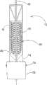
图1是根据本发明的波能转换设备的第一实施例的前顶侧(top front)透视图;1 is a top front perspective view of a first embodiment of a wave energy conversion device according to the present invention;
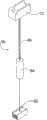
图2是图1的根据本发明的波能转换设备及其相关联张力锚泊系统的前顶侧透视图;Figure 2 is a top front perspective view of the wave energy conversion device of Figure 1 and its associated tension mooring system in accordance with the present invention;
图3是图2的波能转换设备的前视图;Figure 3 is a front view of the wave energy conversion device of Figure 2;
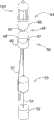
图4是图1的波能转换设备所用的张力锚泊系统的前顶侧透视图;Figure 4 is a top front perspective view of a tension mooring system for the wave energy conversion device of Figure 1;
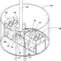
图5是图4的张力锚泊系统中包含的锚泊罐的后底侧(bottom rear)透视图;Figure 5 is a bottom rear perspective view of a mooring tank included in the tension mooring system of Figure 4;
图6a和6b示出了分别在正靠近的波浪的波峰和波谷中的图1和3的波能转换设备;Figures 6a and 6b show the wave energy conversion device of Figures 1 and 3 respectively in the crest and trough of an approaching wave;
图7a和7b示出了在平均水位变化期间的图1和2中的波能转换设备的操作;Figures 7a and 7b illustrate the operation of the wave energy conversion device of Figures 1 and 2 during changes in mean water level;
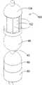
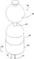
图8是根据本发明的波能转换设备及其相关联锚泊系统的第二实施例的顶侧透视图;Figure 8 is a top side perspective view of a second embodiment of a wave energy conversion device and its associated mooring system according to the present invention;
图9是抵衡机构的局部透明的顶侧透视图,该抵衡机构是与图8的波能转换设备相关联的张力锚泊系统的一部分;9 is a partially transparent top perspective view of a counterbalance mechanism that is part of a tension mooring system associated with the wave energy conversion device of FIG. 8;
图10是图8的波能转换设备和相关联张力锚泊系统的放大透视图;Figure 10 is an enlarged perspective view of the wave energy conversion device and associated tension mooring system of Figure 8;
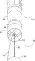
图11是锚泊罐的第一实施例的局部透明的顶侧透视图,该锚泊罐是与图8的波能转换设备相关联的张力锚泊系统的一部分;11 is a partially transparent top side perspective view of a first embodiment of a mooring tank that is part of a tension mooring system associated with the wave energy conversion device of FIG. 8;
图12是锚泊罐的第二实施例的局部透明的顶侧透视图,该锚泊罐是与波能转换设备相关联的根据本发明的张力锚泊系统的一部分;Figure 12 is a partially transparent top side perspective view of a second embodiment of a mooring tank which is part of a tension mooring system according to the present invention associated with a wave energy conversion device;
图13是根据本发明的波能转换设备及其相关联张力锚泊系统的第三实施例的顶侧透视图;Figure 13 is a top side perspective view of a third embodiment of a wave energy conversion device and its associated tension mooring system in accordance with the present invention;
图14是根据本发明的波能转换设备及其相关联张力锚泊系统的第四实施例的顶侧透视图;Figure 14 is a top side perspective view of a fourth embodiment of a wave energy conversion device and its associated tension mooring system in accordance with the present invention;
图15是根据本发明的波能转换设备及其相关联张力锚泊系统的第五实施例的底侧透视图;和15 is a bottom side perspective view of a fifth embodiment of a wave energy conversion device and its associated tension mooring system in accordance with the present invention; and
图16是根据本发明的波能转换设备及其相关联张力锚泊系统的第六实施例的顶侧透视图。Figure 16 is a top side perspective view of a sixth embodiment of a wave energy conversion device and its associated tension mooring system in accordance with the present invention.
具体实施方式Detailed ways
海洋波浪中的能量经由两种正交的能量传播,即水平能量和垂直能量。垂直能量包含在波浪内的水粒子的垂直运动中,即,升沉(heave),并且垂直能量包括波浪的一半可用能量。水平能量包含在波浪内的水粒子的水平运动中,即,纵移(surge),水平能量也包括波浪的一半能量。为了进行波能提取,必须存在对这些正交能量中的一个或两个的能量吸收。The energy in ocean waves travels through two orthogonal energy sources, horizontal energy and vertical energy. Vertical energy is contained in the vertical motion of the water particles within the wave, ie heave, and comprises half the available energy of the wave. The horizontal energy is contained in the horizontal motion of the water particles within the wave, ie surge, and also comprises half the energy of the wave. For wave energy extraction to occur, there must be energy absorption of one or both of these orthogonal energies.
升沉运动描述了波浪的z轴(或,上下)运动,并且与波浪内的垂直能量具有很高的相关性。升沉与波高的亲和性(amicability)使之成为流行且潜在高效的工具来从波浪提取垂直能量。波浪中垂直能量的提取可以在波能转换器(Wave Energy Converter,WEC)中利用单个升沉体(heaving body)或两个升沉体实施。单个升沉体利用水面上的浮力块来提取波浪的垂直能量。为了提取能量,需要差速运动(differential motion),通常在单个升沉体的情况下,第二参照系是海底。利用海底作为参照系,可获得大量的相对运动,并因此,在尽可能宽的频率范围提取大量的能量。Heave motion describes the z-axis (or, up and down) motion of a wave and is highly correlated with the vertical energy within the wave. The amicability of heave to wave height makes it a popular and potentially efficient tool to extract vertical energy from waves. The extraction of vertical energy in waves can be implemented in a Wave Energy Converter (WEC) using a single heaving body or two heaving bodies. A single heave uses buoyant blocks on the water's surface to extract the vertical energy of the waves. To extract energy, differential motion is required, usually in the case of a single heaving body, the second frame of reference is the sea floor. Using the sea floor as a frame of reference, a large amount of relative motion can be obtained, and therefore, a large amount of energy can be extracted over the widest possible frequency range.
单个升沉体设计的实施可通过两个基本构造实现。第一是作为具有附连物的在水上漂浮的浮标,该附连物将浮标联系到其参照系;浮标随波浪在海面上运动,产生相对于参照系的差速运动。第二构造利用固定至海底的结构,该结构位于平均水位以上或以下并且具有附连至该结构的浮标;该浮标将随波浪在水面上振荡,产生相对于该固定坐标系的差速运动。Implementation of a single heave body design can be achieved through two basic configurations. The first is as a buoy floating on water with attachments that tie the buoy to its frame of reference; the buoy moves with waves on the surface of the sea, producing a differential motion relative to the frame of reference. The second configuration utilizes a structure fixed to the sea floor above or below mean water level and having a buoy attached to the structure; the buoy will oscillate with waves on the surface of the water, producing differential motion relative to the fixed coordinate system.
在双升沉体设计中,两个振荡体之间的差速运动用来产生能量;相对的是,单个升沉体设计中的一个升沉体相对于固定参照点的相对运动。然而,在海洋波浪的典型频率范围上,作为振荡系统的双升沉体的效率分析表明双升沉体设计对于任何大的(serious)波能提取都是不实用的。没有商用设施利用这种类型的差速运动的事实,进一步证实了这点。现有升沉浮标的商用形式利用单个振荡体的各种设施。In a double heave body design, differential motion between two oscillating bodies is used to generate energy; in contrast, in a single heave body design, the relative motion of one heave body relative to a fixed reference point. However, an analysis of the efficiency of the double-heave sinker as an oscillatory system over the frequency range typical of ocean waves indicates that the double-heave sinker design is impractical for any serious wave energy extraction. This is further confirmed by the fact that no commercial facility utilizes this type of differential motion. Existing commercial versions of heave buoys utilize the various facilities of a single oscillatory body.
关于本发明的波浪运动的另一方面是纵移运动。如上所述,纵移是沿x轴的运动,并且与从波浪的水平能量提取能量非常相关(amicable)。纵移体能够提取一半的波浪能量,即,波浪的水平能量分量。通过结合纵移和升沉,理论上可以提取100%的海洋波能。明显地,利用能够从这两种矢量提取能量的工具能获得巨大的收益。由于诸如波的非线性、多方向波和其它影响所述体的运动的变量这样的其它因素,这仅仅在理论上是可行的。典型地,本发明的优选实施例寻求利用纵移和升沉二者以便实现优化的波能提取。有利地,本发明的波能转换器利用水翼或滑行艇(hydroplane)来获取海洋波浪中的水平能量。滑行艇能被用来使在波浪中行进的水体(the mass of water)转向,并由此产生沿任意方向的净力。Another aspect of wave motion pertaining to the present invention is longitudinal motion. As mentioned above, pitch is movement along the x-axis and is amicable in extracting energy from the horizontal energy of the wave. The vertical moving body can extract half of the wave energy, ie, the horizontal energy component of the wave. By combining longitudinal movement and heave, it is theoretically possible to extract 100% of the ocean wave energy. Clearly, there are huge benefits to be gained by utilizing tools that can extract energy from these two vectors. This is only theoretically possible due to other factors such as wave non-linearity, multi-directional waves and other variables affecting the motion of the body. Typically, preferred embodiments of the present invention seek to exploit both longitudinal motion and heave in order to achieve optimized wave energy extraction. Advantageously, the wave energy converter of the present invention utilizes hydrofoils or hydroplanes to harvest horizontal energy in ocean waves. A planing craft can be used to turn the mass of water traveling in waves and thereby generate a net force in any direction.
典型地,本发明的波能转换器的优选实施例利用纵移和升沉体设计,该设计使用多自由度来从海洋的行进波浪提取能量。波能转换器将水粒子的这些升沉和纵移运动转化为垂直力,所述垂直力使线性发电机的平移器(translator)与其定子在差动运动中移动。线性发电机将该差速运动转换为可应用于负载的感应电势差,由此允许用海洋波浪的无秩序(chaotic)能量来做有用功。Typically, preferred embodiments of the wave energy converter of the present invention utilize a pitch and heave body design that uses multiple degrees of freedom to extract energy from traveling waves of the ocean. The wave energy converter converts these heave and longitudinal motions of the water particles into vertical forces that move the linear generator's translator and its stator in differential motion. The linear generator converts this differential motion into an induced potential difference that can be applied to the load, thereby allowing the chaotic energy of ocean waves to be used to do useful work.
在本发明波能转换器的优选实施例中,升沉响应(response)没有仅用于转换波浪中的能量。在本发明中,升沉响应还可用来“调节”工作频率,以使得低于其被调节频率的频率经历最小的衰减。根据本发明的张力锚泊系统与波能转换器相关联地被利用,以获得这种可调节性。升沉的这种新颖用法增加了波能转换器的耐受性,而没有牺牲能量提取的效率。这种手段不同于现有技术装置,这些现有装置仅利用所述体(一个或多个)的升沉响应来产生它们的能量。为了清晰,升沉响应是体所经历的响应波浪升沉的垂直振荡。升沉响应仅是浮力和质量的假象(artefact)。根据本发明的张力锚泊系统的可行实施例本身还可以用来从波浪升沉提取能量,以下将详细描述。In a preferred embodiment of the wave energy converter of the present invention, the heave response is not used only to convert energy in waves. In the present invention, the heave response can also be used to "tune" the operating frequency so that frequencies below the frequency at which it is tuned experience minimal attenuation. The tension mooring system according to the invention is utilized in association with a wave energy converter to achieve this adjustability. This novel use of heave increases the tolerance of the wave energy converter without sacrificing the efficiency of energy extraction. This approach differs from prior art devices which utilize only the heave response of the body(s) to generate their energy. For clarity, the heave response is the vertical oscillation experienced by the body in response to wave heave. The heave response is only an artefact of buoyancy and mass. A possible embodiment of the tension mooring system according to the invention can also itself be used to extract energy from wave heave, as will be described in detail below.
波能转换器的优选设计使得其仅包括一个移动(或工作)构件,该构件在通常被称为飞溅区的区域内位于平均水位上方。该系统是利用从波浪中的水粒子的纵移和升沉而来的力的振荡系统。这些力用于向下驱动部分地浸没的结构,而浮子则被向上驱动。优选地,张力锚泊系统与波能转换器相关联,以相对于海底使浸没结构拉紧。两个体的相反运动保证了最大量的差速运动并由此保证从波浪提取的最大量的能量。The preferred design of the wave energy converter is such that it comprises only one moving (or working) member, which is located above the mean water level in an area commonly referred to as the splash zone. The system is an oscillating system utilizing forces derived from the longitudinal movement and heave of water particles in waves. These forces are used to drive the partially submerged structure downwards while the float is driven upwards. Preferably, a tension mooring system is associated with the wave energy converter to tension the submerged structure relative to the sea floor. The opposite movement of the two bodies ensures the maximum amount of differential motion and thus the maximum amount of energy extracted from the waves.
如附图1至7所示,本发明的波浪能量转换设备10的第一实施例包括长的支承结构12,该支承结构被设计用来在海洋中的平均水位上方延伸。设备10利用纵移、升沉、浮力和流体动力来使单个升沉体的最大理论提取能量从50%扩展到100%。支承结构12具有框架的形式,该框架具有与之相连地设置在平均水位以下的浸没构件14。支承结构12还设置有浮力机构,使得支承结构能沿大致直立的取向在海中漂浮。在所示实施例中,浮力机构具有设置在浸没构件14中的浮箱16的形式,将在下文中详细描述。在本实施例中,浮箱16通常充有足够的空气,用来给浸没构件14提供大致的正浮力。在本实施例中,将称其为正浮力浸没构件(positively buoyant submergedmember,PBSM)14。正浮力浸没构件14的浮力延伸超过平均水位,以使得如果水位上升,相关联的浮力也将增加。在替换例中,浸没构件14充有足够的空气,以保证浸没构件的总质量等于其所替换的水的质量,即,浸没构件具有零浮力(neutral buoyancy)。As shown in Figures 1 to 7, a first embodiment of a wave
设备10还包括具有正浮力的漂浮构件18,该漂浮构件可滑动地安装在支承结构12内,以便可在支承结构12内沿垂直方向运动。设备10还包括线性发电机20,该发电机具有与支承结构12相连的定子22以及与漂浮构件18相连的平移器24。该实施例的定子12具有平且长的构造,并且沿支承结构12的中心面垂直地从平均水位以下的正浮力浸没构件(PBSM)14延伸到平均水位以上的位置。在本实施例中,平移器24整合到漂浮构件18的主体中,如以下的详细说明。由线性发电机20产生的电力经由设置在定子22顶端处的电力终端26流出,并且经由适当的水下缆线(未示出)或通过无线(微波)传输而运到海岸。
正浮力浸没构件14的漂浮构件18是一种浮力构件,并且其密度为所替换的水的密度的一半。典型地,漂浮构件还具有小于或者等于浸没构件14体积的体积。这两个参数的结合使得漂浮构件18的质量小于或等于正浮力浸没构件14质量的一半。正浮力浸没构件14的浮力提供的反向力足以抵抗由线性发电机20在其向下的回程时产生的向下力。漂浮构件18可经由低摩擦引导件沿定子22垂直地自由运动。典型地,这些低摩擦引导件能以位于漂浮构件18上的由塑料或塑胶套(未示出)围绕的密封轴承以及定位在定子22上的相应通道或者引导件的形式实施。用于低摩擦引导件的其它可能构造对本领域的技术人员是显而易见的。当波浪运动在漂浮构件18和支承结构12之间引起适当的差速运动时,平移器24相对于定子22平移,线性发电机20产生电力。The
优选地,漂浮构件18设置有水翼/滑行艇表面30,该表面适于将波浪运动的水平分量转换为漂浮构件18的垂直运动,由此增强漂浮构件18的能量提取能力。漂浮构件18包括具有前端32和后端34的长水平横截面,该前端部32适于面对正靠近的波浪的大致方向。前端32变窄为V形尖端。优选地,滑行艇表面30是多个基本上平行的滑行艇表面30中的一个,该多个滑行艇表面垂直于并且沿着漂浮构件18的相应第一和第二侧延伸。滑行艇表面30从漂浮构件18的前端32向下倾斜到后端34。这种构造保证滑行艇表面30迫使正靠近的波浪中的水粒子向下,在滑行艇表面30上产生向上作用的流体动力,这些力加强了由于漂浮构件浮力而作用在漂浮构件上的向上力。Preferably, the
正浮力浸没构件14包括具有前端36和后端38的长水平横截面,该前端36适于面对正靠近的波浪的大致方向。前端36变窄为V形尖端,且正浮力浸没构件14具有像船一样的船身,如图1最清楚地显示。优选地,正浮力浸没构件14具有大致平的上表面40,该上表面从浸没构件的前端36向上倾斜到后端38,其中,平的上表面40迫使从前端靠近的波浪中的水粒子向上,产生作用在正浮力浸没构件14上的向下力。The positively
正浮力浸没构件14被设计为使得对构件的向下运动的抵抗尽可能地最小化。另一方面,通过利用从沿向上方向运动的平的上表面40的粘滞力以及张力锚泊系统的系链力而来的流体动力,正浮力浸没构件14的向上运动(以及进而整个支承结构12的向上运动)受到阻碍。由于波峰中的水粒子冲击漂浮构件18,滑行艇表面30迫使水粒子向下。这在漂浮构件18上产生向上力。另一方面,由于水粒子冲击正浮力浸没构件14,倾斜上表面40迫使水粒子向上。这在正浮力浸没构件14上产生向下力。因此,当波浪冲击设备10时,由于波浪的水平运动,将存在作用在漂浮构件18上的向上力以及作用在正浮力浸没构件14上的向下力。作用于正浮力浸没构件14的向下力将被线性发电机20提供的阻尼抵抗。经由漂浮构件的滑行艇30作用于漂浮构件18的向上力和浮力的结果导致线性发电机20的平移器24的向上运动。通过这些浮力和流体动力的相互作用,漂浮构件18和支承结构12之间的差速运动可以最大化,以便优化通过设备10从波浪中提取的能量。The positively buoyant submerged
为了抵消正浮力浸没构件14上的向上浮力,发明了新颖的张力锚泊系统,该系统的优选实施例具有锚泊机构60的形式,如图4和图5所示。锚泊系统60包括用于锚定装置的配重62,以及用于抵消正浮力浸没构件14的过大浮力的抵衡机构64。配重62和抵衡机构64经由链或索缆66连接,该链或索缆66穿过位于正浮力浸没构件14底部处的滑轮机构68(见图5)。具有机械制动系统70形式的阻尼机构被设置为与滑轮机构68相连,尽管可以利用诸如电或液压或气动阻尼器这样的一些其它阻尼机构。制动系统经由滑轮机构68向索缆施加制动或阻尼动作。制动系统70有效地经由锚泊机构60向正浮力浸没构件14施加制动动作,因而向设备10的支承结构12施加制动动作。典型地,制动系统70为激活螺线管,线性发电机20经由分流电路(shunt circuit)向螺线管(未示出)供电。因此,如果没有电力产生,制动系统70将不工作。制动比(proportion of braking)取决于所产生电流的大小。如果电力需求小或波的频率在线性发电机20的工作参数之外,那么制动系统关闭。然而,如果所产生电力增加,则制动也增大,由此使两个构件之间的差速运动最大化并优化所产生的能量的量。优选地,制动系统被计算机控制。In order to counteract the upward buoyancy forces on the positively buoyant submerged member 14 a novel tension mooring system has been invented, the preferred embodiment of which is in the form of a
图6示出了制动系统70的操作。当所需频率的波通过设备10时,漂浮构件18由于其正浮力和作用在滑行艇表面30上的流体动力而向上移动(图6a)。在该波能提取模式中,线性发电机20产生电力,这导致制动动作经由制动系统70应用于锚泊机构60的索缆66。因此,抵衡机构64将不运动,并且正浮力浸没构件14保持静止。另一方面,随着漂浮构件18返回其下降的位置,如图6b所示,由于被制动系统70保持在位的正浮力浸没构件14的过大浮力,漂浮构件产生电力。当制动系统70关闭时,抵衡机构64能够在索缆66上自由地上下运动。FIG. 6 illustrates the operation of the
通过这种简单的控制系统,可以实现控制正浮力浸没构件14运动的有效且适用机构。当产生能量时,通过仅使用制动系统70,可以使系统上不必要应力大致下降没有能量产生时的数倍。制动系统70具有位于正浮力浸没构件14顶部处的接触开关(未示出),若漂浮构件18运动到其允许的运动的程度,该开关将打开。一旦开关打开,将打开通向螺线管的分流电路,由此允许正浮力浸没构件14高度上升并且释放由漂浮构件18提供的向上应力。这种高度调整将持续直到获得平衡。With such a simple control system, an efficient and adaptable mechanism for controlling the movement of the positively
锚泊机构60被设计成全自动调整系统,将使设备10的平均水位保持在一恒定(consistent)水平。如果设备10离开配重和正浮力浸没构件之间的最短距离,校正力将起作用来使系统回到两点之间的最短距离。由于重力,该校正力是完全自动的力。设备10的自动控制系统使得预定工作范围之外的所有波频被整个支承结构12通过而不只是漂浮构件18。这种手段允许系统自动地校准自身到常用平均水位,由此允许它适应潮汐波动、风暴潮和其它低频现象,如果没有考虑上述现象,将可能导致波能转换器的损坏。The
图7示出了设备10自动校准到平均水位。在这种情况下,波频在设备10的预定工作范围之外,由此漂浮构件18相对于正浮力浸没构件14保持基本静止而不管水位如何,并且没有差速运动来经由线性发电机20产生电力。因此制动系统70保持在不工作状态,锚泊系统60自由运动(freewheel)。抵衡机构64随着平均水位的变化而上下运动,分别如图7a和7b所示。Figure 7 shows the automatic calibration of the
在本实施例中,锚泊机构以锚泊罐72的形式实现,在该锚泊罐中支承结构12的正浮力浸没构件14适于在使用中对接(dock)。图5示出了锚泊罐72的优选实施例。正浮力浸没构件14通过适当的锁定机构固定在锚泊罐72中,该锁定系统可在正浮力浸没构件14在锚泊罐72中对接时自动地锁定正浮力浸没构件14。在所示实施例中,正浮力浸没构件14经由固定螺栓74手动地固定至锚泊罐72。制动系统70和滑轮机构68优选地容纳在锚泊罐72中。需要用于实施本实施例的波能转换设备的所有部件,都可以容纳在该锚泊罐72中。优选地,锚泊罐72具有其自己的浮箱78(未示出),在对接、维护或工作状态期间,当需要在水中提升或降低罐72时,浮箱78可以填充或排出压缩空气。In this embodiment the mooring mechanism is realized in the form of a
锚泊机构60的抵衡机构64主要是质量块(mass),虽然意图该抵衡机构不是完全的惰性质量块(inert mass)。优选地,抵衡机构64包括密度大于水的物质(如混凝土)和在里面的空气腔(未示出)。The
空气腔被设计为使得,当被填充时,将提供具有足够的浮力来向水面举起抵衡机构64。当空气腔填充有水时,它向系统增加额外的质量,由此增加系统用于低频的性能。抵衡机构64的另一方面是间接(remotely)和/或直接地再填充其中的空气腔的能力。当空气腔被再填充时,抵衡机构将升到水面,以使得罐72将定位到抵衡机构64的顶部,由此允许在正浮力浸没构件14上进行的提取或维护。The air cavity is designed such that, when filled, will provide sufficient buoyancy to lift the
抵衡机构64的第二用途是作为自动调试(commissioning)系统。系统的调试使得包括配重62和抵衡机构64的锚泊机构60被设置。抵衡机构64将被留在其浮力状态直到设备10准备好被调试。当设备10要被调试时,设备10附连至暴露的罐72,之后抵衡机构64被注水,因而将设备10自动地设置到其正确的工作位置中,而无需潜水员和高度专业的装备。这种新颖的调试设备10的方式有助于使调试、拆卸(decommissioning)、修理和维护成本最小。替换的构造是使抵衡机构64仅由密度大于水的材料(如混凝土)构成,并且罐72是用于提升和降低抵衡机构64的可调节浮腔。A second purpose of the
设备10使用的线性发电机20被设计用来提供优化的频率响应和电动势(EMF)以允许从海洋波浪中提取大量的能量。通过使线性发电机20的性能参数与机械系统的阻尼需求相匹配来实现这种优化,以使得当系统在满负荷的条件下时,可获得振荡系统的临界阻尼。The
设备10内的线性发电机20使得定子22是大致(predominantly)静止参照系中的振荡体系统的一部分,而平移器24附连至大致运动参照系。在所示实施例中,定子22连接至浸没构件14,而平移器24连接至漂浮构件18。虽然由于通常的命名约定,术语“定子”和“平移器”用来指示预定的波能转换器结构,但实际上这两个部件都将运动。由于定子22和转换器24的运动是主观的(subjective),铜线、磁体和磁渗透材料(magnetic permeablematerial)的位置还可位于定子或平移器上。这些材料的位置取决于设备实施的具体需要或设计标准。The
波能转换设备10被构造为使得便于在船体(vessel)后牵引,由此允许波能转换设备被容易和快速地调试。正浮力浸没构件14的V形船身有利于波能转换设备10的高效牵引。为调试或拆卸设备10,高压空气被应用至位于平均水位以上的阀42。在所示实施例中,阀42位于定子22的顶部处并连接至流体通道(未示出),该通道通过定子22向下延伸至正浮力浸没构件14的主体中的浮箱16。高压空气经由阀42并通过一个流体通道被泵送入浮箱16并且通过另一流体通道从浮箱16排出配重水,由此导致正浮力浸没构件14升至平均水位之上。当浮力构件14在平均水位之上时,将停止能量的产生并且整个支承结构12将作为船,由此允许设备10的容易运输。The wave
当调试设备10时,浮力构件14的任何过大浮力将通过反过程释放,支承结构12再次浸没,并再次开始能量的生产。这类型快速的调配和恢复帮助使调试、修理和维护的成本最低,并且保证了最可靠的能量供应。When the
设备10的其它方面优势在于,其被设计为响应特定波频范围,用于发电。在所示实施例中,设备10的水平长度大约为5米,相应于海洋波长20米的四分之一。该特征在应用于海洋时特别有用,因为频率越低,可从海洋中获得的能量越多。过去,很多波能转换器在风暴条件下因为经历过大波能密度而遗失。通过设备10的频率调节能力,可以仅从预定频率提取能量,并同时简单地使破坏性的高能量密度波通过,而没有衰减。设备10的耐受性非常明显,更不用提当其它波能转换器无法工作以确保它们的幸存时,该设备10所能产生电力的利益。An additional advantage of the
波能转换设备10可以构建成模块单元和多个连接在一起并作为波能转换电力阵列或电力矩阵的这样的模块单元中的一个。在所示实施例中,支承结构12的框架具有大致矩形的构造。这种形状方便多个模块单元沿两个正交方向并排地互连。The wave
图8至11示出了根据本发明的波能转换设备44及其相关联张力锚泊系统50的第二实施例。波能转换设备44包括被设计为在海洋中的平均水位上方延伸的长支承结构45。支承结构45具有垂直取向的柱形式,该柱包括与之连接地设置在平均水位以下的浸没构件46。本实施例的支承结构45还设置有浮力机构,使得支承结构沿大致直立的取向在海中漂浮。在所示实施例中,浮力机构具有设置在浸没构件46中的浮箱47(未示出)的形式。如前述实施例,浮箱47通常填充有足够的空气,用来给浸没构件46提供大致的正浮力。Figures 8 to 11 show a second embodiment of a wave
设备44还包括具有正浮力的漂浮构件48,该漂浮构件可滑动地安装在支承结构45上,以便可沿垂直方向运动。在本实施例中,漂浮构件48具有球形构造,并且可滑动地安装在支承结构45的垂直柱上。设备44还包括线性发电机49,该发电机具有被设置为与支承结构45的垂直柱相连的定子和整合到漂浮构件48的主体内的平移器。为将海洋波能转换为电力,本实施例的波浪转换设备44的操作与第一实施例10的类似,此处不再详细描述。如前述实施例,球形漂浮构件48的流体动力和浮力特性使线性发电机49的平移器相对于定子产生差速运动。有利地,浸没构件46的上表面具有大致半球形的构造,以便用作水的偏转表面(与第一实施例中的上表面40不同),来进一步增强该差速运动。The
本实施例的张力锚泊系统50包括长的柔性构件,该构件具有从配重机构52延伸到抵衡机构53的索缆51的形式,适于经由滑轮机构54从浸没构件46悬挂下来。配重机构52可具有大块混凝土的形式,或替换地利用适当的海床锚泊将缆索51的一端锚定至海底。抵衡机构53包括质量块,该质量块具有与之相连的可调浮箱,如图9所示。The
本实施例的抵衡机构53具有中空容器55的形式,该容器包括具有预定质量的实心底部,用作用于浸没构件46的平衡重量(counterweight)。容器55的其余体积可经由空气软管57填充压缩空气以调整容器55的浮力。阀58可设置在容器55的壁中以将空气排出到周围的海洋中。索缆51的另一端连接至容器55的顶部并且延伸到滑轮机构54,之后向下穿过沿容器55的中轴线垂直延伸的中空通道59到配重机构52。The counterbalancing
通过调整容器55的浮力,经由索缆51作用于浸没构件46的抵衡力可被改变。以此方式,波能转换设备44及其相关联张力锚泊系统50的共振频率可被调整以便将其“调节”至盛行(prevailing)海洋条件。优选地,容器55的底部56的质量被设定以匹配系统的最小所需工作频率。因为由底部56给系统提供的低浮心和低质心,该质量还有助于保持波能转换设备44沿直立取向。随着容器55的质量减小,系统的共振频率增加。By adjusting the buoyancy of the
滑轮机构54容纳在锚泊罐80中,该罐在图11和12中以透明壁示出。在本实施例中,锚泊罐80具有筒状形状以匹配浸没构件46的形状,并且永久或可松脱地附连至浸没构件46的底部。图11可清楚地看出,滑轮机构54包括固定地安装在轴84上的滑轮82,该轴可旋转地安装在一对旋转发电机86a和86b之间。由于轴84振荡,发电机86a和86b将产生电动势并提供对轴的旋转运动的阻力。发电机86由此提供阻尼机构,用于对轴84的旋转进而对滑轮82的旋转施加阻尼动作。当负载应用于发电机86时,它们有效地经由滑轮82将阻尼动作施加至索缆51,并且因此通过抵衡机构53施加至浸没构件46的运动。The
如果需要,由发电机86产生的电能可存储在容纳于罐80内的电池88中。电能转换和控制模块90可被设置用于将发电机86产生的交流电转换为直流电用于存储在电池88中。能量转换和控制模块还可被构造为使罐本身成为波能转换设备,如下文详细描述。微处理器操纵的控制系统92也设置在锚泊罐80内,以提供张力锚泊系统50的所有部件的自动控制。控制系统92监视波浪的频率并相应地调整抵衡机构的质量。Electrical energy generated by generator 86 may be stored in
空气压缩器94设置在锚泊罐80内,用于经由空气软管57将空气向下泵送至抵衡机构53。一些由发电机86产生的电力用于为空气压缩器94供电。空气压缩器94也在控制系统92的控制之下。空气管道96从大气向空气压缩器94供应空气,并且穿过浸没体46向上延伸至一吃水线(water line)之上的点。抵衡机构53的中空容器55内的空气不必排出至周围的海洋,而能被泵送回容纳在锚泊罐80或浸没构件中的压力容器(未示出)。An
将参照图8至11描述用于张力锚泊系统50的典型操作顺序:A typical sequence of operations for the
给出特定的工作环境,控制系统92经由诸如加速度计这样的适当机构测量并计算系统所面临的波浪频率。通过利用公知公式的计算来确定主要和/或能量最密集频率(most energy dense frequency)。一旦选定优化工作频率,仍通过公知公式计算允许提取最多能量的优化系统质量。Given the particular operating environment, the
然后,控制系统92计算当前系统质量并且确定需要在系统中引入或去除的水的体积,以实现系统的这个优化质量。如果质量需要减少,那么控制系统92将起动空气压缩器94,以将空气泵送至中空罐体55来通过正压力置换(displacement)来排出存在于中空罐体55内的水,如潜艇一样。如果质量需要增加,那么控制系统92打开空气阀58来排出中空容器55内的空气或起动空气压缩器94以将空气泵送至替换存储箱,由此允许水填充排空的体积并增加系统质量。The
以此方式,控制系统92将质量移入或移出张力锚泊系统,因而通过质量变化改变系统的工作特性并且允许系统在常变环境中被调节以最佳地工作。In this way, the
在锚泊罐80中可利用任何适当的阻尼机构用于向浸没构件46的运动施加阻尼动作。如果发电机86能够直接用作电力源,将是特别有利的。然而,液压泵也能用来提供阻尼动作。图12示出了锚泊罐80的替换实施例,其与图11的实施例基本相同,但是旋转发电机86被一对液压泵98替代,以提供阻尼机构。两个液压泵98a和98b可操作地通过各自的带和滑轮系统99a和99b联接至轴84。例如,液压泵98例如可用于经由软管向液压操作发电机或液压蓄能器泵送液压液(油、海水)。气压泵可替代液压泵98使用。Any suitable damping mechanism may be utilized in the
如图8和10所示的波能转换设备44并入有安装在设备的支承结构45的顶部上的风力涡轮机100。风力涡轮机100提供了捕获另一种可再生能源、即海洋风的机构。涡轮机被定向为绕垂直轴线旋转,并且设置有一系列叶片102用来捕获风并产生电力。旋转发电机(未示出)容纳在风力涡轮机100的底部中。由风力涡轮机100产生的电力可被储存在电池88中,或经由缆线或无线地利用微波发射机(未示出)发送至岸上。涡轮机顶部上可见的圆顶104用来容纳发射机和/或GPS或一些其它形式的定位信标。The wave
当然,不具有风力涡轮机100的波能转换设备44将非常令人满意地工作。不具有涡轮机的设备44的实施例如图13所示。如果需要,波能转换设备44还可安装太阳能电池板108以利用第三种可再生能源,即太阳光。图14示出了具有多个安装在风力涡轮机100的顶部上的太阳能电池板108的设备44的实施例。在其它方面,该实施例(及前述实施例)的具有相关联张力锚泊系统50的波能转换设备44与图8至11所示实施例的大致相同,这里不再描述。Of course, the wave
图15示出了波能转换设备110的第四实施例,其与图8至11所示的实施例类似,并因此相同的参考标号将用于标识类似部件。Fig. 15 shows a fourth embodiment of a wave
在设备110的该实施例中,锚泊罐80的壳体在底部是敞开的,以便允许海水填充到中空内部内没有被张力锚泊系统50的部件占用的空间中。在每个前述实施例中,容纳在罐80内的张力锚泊罐所有部件被封装在气密和水密封壳中,保护它们不受海水腐蚀影响。In this embodiment of the
锚泊罐80的敞开底部建立了空气腔112,该空气腔可部分地填充有空气以便给锚泊罐提供零浮力。因为腔112敞开至周围海洋,由于波浪运动,它的浮力将随着流体静压的变化而变化。当每个波峰通过时,由于流体静压增加,零浮力锚泊罐80的浮力将降至负浮力。当设备110进入波谷时,由于产生正浮力,锚泊罐将上升。直接连接至浸没构件46的锚泊罐的浮力中的这些变化,与漂浮构件48的垂直运动成180°相位差,因而将有助于进一步增加线性发电机49的定子和平移器的差速运动。The open bottom of the
如前文所述,本发明的张力锚泊系统本身可用作波能转换设备。图16示出了张力锚泊系统120本身被构造为波能转换设备的实施例。在本实施例中,锚泊罐80直接安装至浮力筒122的下侧。不存在前述实施例中的线性发电机。与图8至11的实施例相似,在本实施例中,筒122具有安装在顶部上的风力涡轮机100。张力锚泊系统120以与图8至11的实施例类似的方式工作,但在这种情况下,控制系统被构造为,发电机86以最大效率工作以产生电力,这是因为它们现在不再用作阻尼机构。张力锚泊系统120仍然作为振荡系统工作,该振荡系统能调节至海洋中的波浪频率以从筒122的升沉响应中提取最大能量。As previously mentioned, the tension mooring system of the present invention can itself be used as a wave energy conversion device. Figure 16 shows an embodiment where the
至此已详细描述了波能转换设备和张力锚泊系统的几个实施例,显而易见的是,与现有技术相比,本设备的实施例提供多个优点,包括:Having thus far described several embodiments of the wave energy conversion device and tension mooring system in detail, it is apparent that embodiments of the device provide several advantages over the prior art, including:
(i)波能转换器为鲁棒(robust)设计,具有最小的损坏可能性,能够经受大部分气候条件。(i) The wave energy converter is a robust design with minimal possibility of damage and is able to withstand most climatic conditions.
(ii)张力锚泊系统能使得波能转换设备调节至盛行海洋条件以保持最大效率。(ii) The tension mooring system enables the wave energy conversion device to adjust to prevailing ocean conditions to maintain maximum efficiency.
(iii)张力锚泊系统适用于任何浮力类型波能转换设备以提高其工作效率。(iii) The tension mooring system is suitable for any buoyancy type wave energy conversion equipment to improve its working efficiency.
(4)其是万能的,能从较大范围的波高、波频和波向的波浪中提取能量。(4) It is universal and can extract energy from waves with a wide range of wave heights, wave frequencies and wave directions.
(5)其非常高效,利用纵移、升沉、浮力、流体静压和流体动压来从波浪中提取最大能量。(5) It is very efficient, using longitudinal movement, heave, buoyancy, hydrostatic pressure and hydrodynamic pressure to extract maximum energy from waves.
对于本领域的技术人员显而易见的是,除了已描述内容外,还可对所述实施例进行各种修改和改进,而不偏离本发明的基本构思。例如,定子不必位于设备的中心面或轴线上,而可位于波能转换设备的支承结构中的任何位置。因此,应该理解的是,本发明的范围不限于所述的具体实施例并被所附权利要求限定。It will be apparent to those skilled in the art that various modifications and improvements, besides what has been described, can be made to the described embodiments without departing from the basic idea of the invention. For example, the stator need not be located on the center plane or axis of the device, but can be located anywhere in the support structure of the wave energy conversion device. Therefore, it should be understood that the scope of the invention is not limited to the particular embodiments described and is defined by the appended claims.
Claims (29)
Applications Claiming Priority (3)
| Application Number | Priority Date | Filing Date | Title |
|---|---|---|---|
| AU2006903707 | 2006-07-11 | ||
| AU2006903707AAU2006903707A0 (en) | 2006-07-11 | Wave Energy Converter | |
| PCT/AU2007/000940WO2008006145A1 (en) | 2006-07-11 | 2007-07-09 | Wave energy converter |
Related Child Applications (2)
| Application Number | Title | Priority Date | Filing Date |
|---|---|---|---|
| CN2011101533692ADivisionCN102322387A (en) | 2006-07-11 | 2007-07-09 | The equipment that is used for converting wave energy |
| CN2011101529625ADivisionCN102345281A (en) | 2006-07-11 | 2007-07-09 | Floating member of wave energy converter |
Publications (2)
| Publication Number | Publication Date |
|---|---|
| CN101490341Atrue CN101490341A (en) | 2009-07-22 |
| CN101490341B CN101490341B (en) | 2011-07-27 |
Family
ID=38922835
Family Applications (3)
| Application Number | Title | Priority Date | Filing Date |
|---|---|---|---|
| CN2007800263683AExpired - Fee RelatedCN101490341B (en) | 2006-07-11 | 2007-07-09 | Wave energy converter |
| CN2011101533692APendingCN102322387A (en) | 2006-07-11 | 2007-07-09 | The equipment that is used for converting wave energy |
| CN2011101529625APendingCN102345281A (en) | 2006-07-11 | 2007-07-09 | Floating member of wave energy converter |
Family Applications After (2)
| Application Number | Title | Priority Date | Filing Date |
|---|---|---|---|
| CN2011101533692APendingCN102322387A (en) | 2006-07-11 | 2007-07-09 | The equipment that is used for converting wave energy |
| CN2011101529625APendingCN102345281A (en) | 2006-07-11 | 2007-07-09 | Floating member of wave energy converter |
Country Status (16)
| Country | Link |
|---|---|
| US (2) | US8264093B2 (en) |
| EP (1) | EP2047037A1 (en) |
| JP (1) | JP2009542964A (en) |
| KR (3) | KR101618112B1 (en) |
| CN (3) | CN101490341B (en) |
| AR (1) | AR061884A1 (en) |
| AU (3) | AU2007272290B2 (en) |
| BR (1) | BRPI0714385A2 (en) |
| CA (1) | CA2657558A1 (en) |
| IL (1) | IL196445A0 (en) |
| MX (1) | MX2009000329A (en) |
| NO (1) | NO20090183L (en) |
| NZ (1) | NZ574786A (en) |
| TW (1) | TW200827544A (en) |
| WO (1) | WO2008006145A1 (en) |
| ZA (1) | ZA200900965B (en) |
Cited By (9)
| Publication number | Priority date | Publication date | Assignee | Title |
|---|---|---|---|---|
| CN102542898A (en)* | 2010-12-30 | 2012-07-04 | 刘陈英 | Experimental device for building pyramid with power generating function, energy manufacturing device and operating method thereof |
| CN102556291A (en)* | 2012-01-13 | 2012-07-11 | 中国科学院广州能源研究所 | Suspending anti-typhoon system for floating type wave energy power generation device |
| CN102317617B (en)* | 2008-12-15 | 2014-12-10 | 格威夫有限公司 | A system that generates energy through wave action |
| CN107643381A (en)* | 2017-10-16 | 2018-01-30 | 国家海洋局第二海洋研究所 | A kind of automatic profiling observation device of ocean wave energy driving |
| US9944353B2 (en) | 2012-06-04 | 2018-04-17 | Gwave Llc | System for producing energy through the action of waves |
| US9976535B2 (en) | 2005-11-07 | 2018-05-22 | Gwave Llc | System for producing energy through the action of waves |
| CN108884807A (en)* | 2016-04-06 | 2018-11-23 | M·德拉吉奇 | Device for converting wave energy into electrical energy and method for deploying it at a mining location |
| CN115023546A (en)* | 2019-06-25 | 2022-09-06 | 拉杰什·冈朱尔 | Closely interconnected wave energy harvester system including self-directing power take-off |
| CN116044644A (en)* | 2023-02-09 | 2023-05-02 | 中国船舶重工集团柴油机有限公司 | Buoyancy pendulum type wave power generation device |
Families Citing this family (67)
| Publication number | Priority date | Publication date | Assignee | Title |
|---|---|---|---|---|
| US8915078B2 (en) | 2005-11-07 | 2014-12-23 | Gwave Llc | System for producing energy through the action of waves |
| US8519557B2 (en) | 2005-11-07 | 2013-08-27 | Gwave Llc | System for producing energy through the action of waves |
| CN101490341B (en)* | 2006-07-11 | 2011-07-27 | 澳大利亚持续能源有限公司 | Wave energy converter |
| EP2231933A1 (en)* | 2007-12-12 | 2010-09-29 | Protean Power Pty Ltd | Improvements to wave energy converter |
| CN101981312B (en) | 2008-02-29 | 2015-09-23 | 辛格尔浮筒系船公司 | Offshore combined power generation system |
| CN102027229A (en)* | 2008-04-11 | 2011-04-20 | 澳大利亚持续能源有限公司 | System and method for deploying and retrieving a wave energy converter |
| US8007231B2 (en)* | 2008-07-17 | 2011-08-30 | Dennis Gray | Flowing water energy device |
| KR101082076B1 (en)* | 2008-10-08 | 2011-11-10 | 신익수 | Wave-power generating module, wave-power generating unit comprising the wave-power generating module, and wave-power generating apparatus comprising the wave-power generating unit |
| US20100148509A1 (en)* | 2008-12-12 | 2010-06-17 | Israel Ortiz | Ortiz turbine |
| GB2475853B (en)* | 2009-12-01 | 2015-11-04 | Straumekraft As | Wave powered buoyancy control system for floating wave power plants |
| GB2476276B (en) | 2009-12-18 | 2015-10-21 | Alstom Renewable Technologies | Foundation structure |
| WO2011079199A1 (en)* | 2009-12-23 | 2011-06-30 | Resolute Marine Energy, Inc. | Output stabilized wave energy conversion device and method |
| CA2799573C (en)* | 2010-05-28 | 2018-05-15 | Seabased Ab | A wave power unit, a use of a such and a method of producing electric energy |
| DE102010025907A1 (en)* | 2010-07-02 | 2012-01-05 | Robert Bosch Gmbh | Wave energy converter for the conversion of kinetic energy into electrical energy |
| US8441139B2 (en)* | 2010-10-10 | 2013-05-14 | Reza Karimi | Apparatus for converting wave, solar and wind energy |
| KR101179668B1 (en) | 2010-12-23 | 2012-09-10 | 한국지질자원연구원 | Compressed air storage and electricity generating system connected with offshore wind farm and Compressed air storage tank |
| US9657710B2 (en)* | 2011-03-01 | 2017-05-23 | Bruce Gregory | Dynamic tuning for wave energy conversion |
| NO20110813A1 (en)* | 2011-06-06 | 2012-10-15 | Oevretveit Hans Aage | Wave power plants |
| KR101258063B1 (en)* | 2011-07-12 | 2013-04-30 | 경주대학교 산학협력단 | Wave activated power generation unit |
| CN103261677B (en)* | 2011-07-27 | 2017-04-12 | Dlz公司 | Horizontal-axis hydrokinetic water turbine system |
| US8525363B2 (en)* | 2011-07-27 | 2013-09-03 | Dlz Corporation | Horizontal-axis hydrokinetic water turbine system |
| US8786122B2 (en) | 2011-07-27 | 2014-07-22 | Dlz Corporation | Horizontal-axis hydrokinetic water turbine system with water pump |
| US9115687B2 (en)* | 2012-02-25 | 2015-08-25 | Atargis Energy Corporation | Efficient wave energy conversion using cycloidal turbines |
| PT106272B (en)* | 2012-04-26 | 2014-07-15 | Francisco José Marques Da Cruz Rosa | ENGINE GENERATOR GROUP |
| JP6273422B2 (en)* | 2012-06-13 | 2018-02-07 | 木村 光照 | Wave power generation system and transmission body and rotation conversion unit used therefor |
| US20130341926A1 (en)* | 2012-06-25 | 2013-12-26 | John Edward Fay | Wavewheel |
| FI124102B (en)* | 2012-06-27 | 2014-03-14 | Wello Oy | Wave power |
| DE102012106009B4 (en)* | 2012-07-05 | 2015-07-23 | Achim Humm | Apparatus for obtaining electrical energy from sea waves |
| US8723353B1 (en) | 2012-11-21 | 2014-05-13 | Barrie Franklin | Wave energy converter design incorporating an induction generator |
| KR101525435B1 (en)* | 2013-03-07 | 2015-06-09 | 김종근 | Power generating equipment using wave forces |
| US9074577B2 (en) | 2013-03-15 | 2015-07-07 | Dehlsen Associates, Llc | Wave energy converter system |
| FI124925B (en) | 2013-09-18 | 2015-03-31 | Wello Oy | Gyrating wave power plant |
| US10174740B2 (en) | 2013-09-26 | 2019-01-08 | Mitsuteru Kimura | Wave-power generation system, and transmission body and rotation conversion unit used therefor |
| US9140231B1 (en)* | 2013-10-07 | 2015-09-22 | Sandia Corporation | Controller for a wave energy converter |
| WO2016014947A2 (en)* | 2014-07-24 | 2016-01-28 | Oscilla Power Inc. | Method for deploying and recovering a wave energy converter |
| US10458136B2 (en)* | 2014-08-25 | 2019-10-29 | Thomas J. Lochtefeld | Method and apparatus for producing waves suitable for surfing using wave-forming caissons with floating wave attenuator |
| CN104314743A (en)* | 2014-10-14 | 2015-01-28 | 中国海洋大学 | Adaptive traction-type tidal current energy power generation device |
| WO2016069636A2 (en) | 2014-10-27 | 2016-05-06 | Principle Power, Inc. | Connection system for array cables of disconnectable offshore energy devices |
| BE1023072A1 (en)* | 2015-04-14 | 2016-11-16 | Louis Stevens | System of storage and electric power generation in marine environment |
| EP3347591B1 (en)* | 2015-09-08 | 2019-11-13 | CPG Technologies, LLC. | Long distance transmission of offshore power |
| CA3005792C (en)* | 2015-11-18 | 2020-06-30 | Pruthvi Raj AVADHUTA | An apparatus for power generation from the surface ocean waves in deep seas |
| JP6966545B2 (en)* | 2016-07-28 | 2021-11-17 | バーデックス コーポレイション | Wave energy transducer with depth-adjustable paravanes |
| TWI662185B (en)* | 2016-08-31 | 2019-06-11 | 沛康實業有限公司 | Electricity generation device by using buoyancy and modular electricity generation apparatus |
| AU2017385006B2 (en)* | 2016-09-11 | 2023-03-30 | Lone Gull Holdings, Ltd. | Inertial wave energy converter |
| US10087909B2 (en)* | 2016-09-11 | 2018-10-02 | Garth Alexander Sheldon-Coulson | Inertial wave energy converter |
| DK179738B1 (en) | 2017-10-11 | 2019-04-30 | Ravn Niels | Wind-Driven Energy Converting Device |
| KR102386008B1 (en)* | 2017-12-06 | 2022-04-12 | 폴리테크니코 디 토리노 | A system that generates electrical energy from waves in the ocean |
| KR101970640B1 (en)* | 2018-03-13 | 2019-04-19 | 임성만 | Floating solar power generating plant |
| US11156201B2 (en)* | 2018-05-17 | 2021-10-26 | Lone Gull Holdings, Ltd. | Inertial pneumatic wave energy device |
| US10526056B1 (en)* | 2019-04-29 | 2020-01-07 | Physician Electronic Network, LLC | Generation of electric power using wave motion, wind energy and solar energy |
| US11293398B2 (en)* | 2019-06-06 | 2022-04-05 | Oscilla Power, Inc. | Drivetrain for a wave energy converter |
| US11062821B1 (en)* | 2019-06-18 | 2021-07-13 | Facebook, Inc. | Intermediate node to power submarine cable system |
| US12326131B2 (en) | 2020-08-12 | 2025-06-10 | Riahmedia Inc. | Systems and methods for harnessing marine hydrokinetic energy |
| US20240010309A1 (en)* | 2020-11-21 | 2024-01-11 | G8 Subsea Pte. Ltd. | Floating platform for renewable energy |
| US11654780B2 (en) | 2020-12-17 | 2023-05-23 | Consolidated Metco, Inc. | Vehicle electronic control unit and method |
| CN112937765A (en)* | 2021-03-29 | 2021-06-11 | 中国海洋大学 | Composite anchoring system and danger avoiding method of small floating type wave energy device |
| US11401155B1 (en)* | 2021-05-06 | 2022-08-02 | Bluewater Energy Services B.V. | System for transferring crude oil from an onshore location to a vessel |
| WO2022261109A1 (en) | 2021-06-10 | 2022-12-15 | Bardex Corporation | Parametric wave energy, subsea power generation |
| US12085053B2 (en) | 2021-06-22 | 2024-09-10 | Riahmedia Inc. | Systems and methods for power distribution and harnessing of marine hydrokinetic energy |
| US12215662B2 (en)* | 2021-08-31 | 2025-02-04 | Alliance For Sustainable Energy, Llc | Two-body variable geometry wave energy converter |
| KR20230050576A (en)* | 2021-10-08 | 2023-04-17 | 주식회사 인진 | Wave generation system |
| KR20230050578A (en)* | 2021-10-08 | 2023-04-17 | 주식회사 인진 | Wave generation system |
| CN114278492B (en)* | 2021-12-21 | 2022-11-11 | 北科创新(深圳)科技有限公司 | A tidal wave energy combined power generation device |
| KR102554350B1 (en)* | 2021-12-24 | 2023-07-11 | 한국해양과학기술원 | Buoy type wave power generation apparatus |
| CN114411622B (en)* | 2022-02-16 | 2024-07-23 | 嵊州市浙江工业大学创新研究院 | Floating breakwater based on piezoelectric effect |
| CN115973385B (en)* | 2023-01-05 | 2024-12-13 | 吉林大学 | Submerged buoy docking system |
| CN118992003B (en)* | 2024-09-04 | 2025-02-18 | 青岛星汉微电子技术开发有限公司 | Composite hydrofoil and mobile platform adopting same |
Family Cites Families (48)
| Publication number | Priority date | Publication date | Assignee | Title |
|---|---|---|---|---|
| GB1507916A (en)* | 1975-04-28 | 1978-04-19 | Wavepower Ltd | Apparatus for extracting energy from wave movement of water |
| JPS5322934A (en) | 1976-08-14 | 1978-03-02 | Kaiyou Kaihatsu Gijiyutsu Kenk | Wave force generating set |
| JPS5426692A (en) | 1977-08-01 | 1979-02-28 | Furukawa Electric Co Ltd:The | Detection method of failed location in terpetature sensor |
| GB1601219A (en)* | 1977-08-31 | 1981-10-28 | Energy Secretary Of State For | Devices for extracting energy from wave power |
| FR2409181A1 (en)* | 1977-11-16 | 1979-06-15 | Jourdan Louis | AMPHIBIOUS BEACHED PONTOONS AND LOURDES CHARGES DISPLACEMENT MEANS |
| AU528441B2 (en)* | 1978-09-07 | 1983-04-28 | Bernard Arthur Packer | Energy generating buoyancy member |
| JPS55127886U (en)* | 1979-03-05 | 1980-09-10 | ||
| US4367982A (en)* | 1980-09-04 | 1983-01-11 | Mobil Oil Corporation | Safety device for anchored marine structure |
| US4455824A (en)* | 1981-06-01 | 1984-06-26 | Gustav Dabringhaus Revocable Trust | Wave motor |
| US4434375A (en)* | 1982-06-30 | 1984-02-28 | Taylor Robert N | Wave energy converter |
| AU4263385A (en)* | 1984-06-15 | 1985-12-19 | Teplow, P. | Generator utilising wave energy |
| JPS6158977A (en)* | 1984-08-30 | 1986-03-26 | Muroran Kogyo Daigaku | Method of generating electrical power with use of wave force and device therefor |
| CA1278224C (en)* | 1985-05-10 | 1990-12-27 | John T. Hepburn, Limited | Anchoring system for floating structure |
| US4754157A (en)* | 1985-10-01 | 1988-06-28 | Windle Tom J | Float type wave energy extraction apparatus and method |
| JPS62198351A (en) | 1986-02-26 | 1987-09-02 | Morinaga Milk Ind Co Ltd | Milk composition substitute for mother's milk |
| JPS62199078A (en) | 1986-02-27 | 1987-09-02 | Toshiba Corp | Gas laser oscillator |
| JPH0528387Y2 (en)* | 1987-12-26 | 1993-07-21 | ||
| JPH0528388Y2 (en)* | 1987-12-29 | 1993-07-21 | ||
| AU1011592A (en)* | 1992-01-09 | 1993-07-15 | Herbert Blair Ohlson | Electricity generating facility |
| DE4338103A1 (en)* | 1993-11-08 | 1995-05-11 | Wolf Klemm | Device for obtaining electric energy (power) with the aid of the kinetic energy of water waves |
| JP2775225B2 (en)* | 1993-12-28 | 1998-07-16 | 矢崎総業株式会社 | Connector housing |
| KR100221980B1 (en)* | 1995-04-06 | 1999-09-15 | 심현진 | Wave power generation method and system thereof |
| SE508307C2 (en)* | 1996-04-29 | 1998-09-21 | Ips Interproject Service Ab | wave energy converters |
| US5827011A (en)* | 1996-12-23 | 1998-10-27 | Kann; Dirk C. | Wave suppression system |
| DE19958409A1 (en) | 1999-12-03 | 2001-06-13 | Peter Kimmig | Tide, flood and oceanic wave powered electricity generator to produce electric current; has trough floating in water between posts anchored in sea-bed, which rises and sinks by waves or tide |
| US6305877B1 (en)* | 2000-03-06 | 2001-10-23 | The United States Of America As Represented By The Secretary Of The Navy | Breakwater/attenuation device for high speed vessel wake |
| US6768216B1 (en)* | 2000-05-26 | 2004-07-27 | Ocean Power Technologies, Inc. | Wave energy converters utilizing pressure differences |
| GB0205732D0 (en)* | 2001-03-16 | 2002-04-24 | Sanchez Gomez Gines | Floating platform to obtain electric power from the sea waves |
| KR100416923B1 (en)* | 2001-04-20 | 2004-01-31 | 주식회사 신성기연 | Buoy having self generating device of electricity using power of waves |
| JP2002332946A (en) | 2001-05-02 | 2002-11-22 | Tomiji Watabe | High output wave activated power generation buoy |
| AUPS028102A0 (en) | 2002-02-04 | 2002-02-28 | Nielsen, Ken Gylden Holm | Golden holm power plant |
| US6768217B2 (en)* | 2002-02-20 | 2004-07-27 | Ocean Power Technologies, Inc. | Wave energy converter system of improved efficiency and survivability |
| WO2003087569A1 (en)* | 2002-04-04 | 2003-10-23 | Lunatech, Llc | Barge-mounted tidal-powered desalinization system |
| WO2003098033A1 (en)* | 2002-05-16 | 2003-11-27 | Pruthivi Raj Avadhuta | An apparatus for power generation from ocean tides / wave motion (sagar lehar vidyut shakti) |
| ES2224832B1 (en)* | 2003-01-10 | 2005-11-01 | Pipo Systems, S.L. | MULTIPLE ENGINEERING AND COMPLEMENTARY TRANSFORMATION SYSTEM OF ENERGY FROM THE WAVES OF THE SEA. |
| US6930406B2 (en)* | 2003-02-19 | 2005-08-16 | W. C. Gray Montgomery | Tide compensated swell powered generator |
| NO322609B1 (en)* | 2003-06-23 | 2006-10-30 | Fobox As | Bolgekraftverk. |
| KR100531078B1 (en)* | 2003-07-09 | 2005-11-24 | 차봉열 | Marking buoy device using wave-force generation |
| AU2003903645A0 (en)* | 2003-07-11 | 2003-07-31 | Davidson, Aaron | Extracting energy from fluids |
| AU2004100389A4 (en)* | 2004-05-25 | 2004-07-08 | Nesvaderani, Ali Reza Mr | Tidal Power Plant |
| AU2006320515C1 (en)* | 2005-12-01 | 2012-03-01 | Ocean Power Technologies, Inc. | Wave energy converter utilizing internal reaction mass and spring |
| US7420287B2 (en)* | 2006-03-28 | 2008-09-02 | Aleksandr Smushkovich | Intermittent force powered electromagnetic converters especially for sea waves |
| NO325962B1 (en)* | 2006-05-31 | 2008-08-25 | Fobox As | Device for converting bulge energy |
| NO325929B1 (en)* | 2006-05-31 | 2008-08-18 | Fobox As | Device for absorption of bulge energy |
| US7525214B2 (en)* | 2006-06-14 | 2009-04-28 | Nova Oceanic Energy Systems | Wave-power system and method for generating energy at constant rotational speed at variable significant wave heights and periods |
| CN101490341B (en)* | 2006-07-11 | 2011-07-27 | 澳大利亚持续能源有限公司 | Wave energy converter |
| US20090121486A1 (en)* | 2007-10-11 | 2009-05-14 | Ganley Declan J | Tidal Power System |
| BRPI0801714A2 (en)* | 2008-03-18 | 2009-11-03 | Eduardo Metzen | marine generator |
- 2007
- 2007-07-09CNCN2007800263683Apatent/CN101490341B/ennot_activeExpired - Fee Related
- 2007-07-09CNCN2011101533692Apatent/CN102322387A/enactivePending
- 2007-07-09USUS12/373,421patent/US8264093B2/ennot_activeExpired - Fee Related
- 2007-07-09JPJP2009518680Apatent/JP2009542964A/enactivePending
- 2007-07-09MXMX2009000329Apatent/MX2009000329A/ennot_activeApplication Discontinuation
- 2007-07-09WOPCT/AU2007/000940patent/WO2008006145A1/enactiveApplication Filing
- 2007-07-09CACA002657558Apatent/CA2657558A1/ennot_activeAbandoned
- 2007-07-09KRKR1020147030953Apatent/KR101618112B1/ennot_activeExpired - Fee Related
- 2007-07-09KRKR1020097002839Apatent/KR101521882B1/ennot_activeExpired - Fee Related
- 2007-07-09CNCN2011101529625Apatent/CN102345281A/enactivePending
- 2007-07-09BRBRPI0714385-0Apatent/BRPI0714385A2/ennot_activeIP Right Cessation
- 2007-07-09AUAU2007272290Apatent/AU2007272290B2/ennot_activeCeased
- 2007-07-09KRKR1020147030952Apatent/KR101548676B1/ennot_activeExpired - Fee Related
- 2007-07-09EPEP07719171Apatent/EP2047037A1/ennot_activeWithdrawn
- 2007-07-09NZNZ574786Apatent/NZ574786A/ennot_activeIP Right Cessation
- 2007-07-11TWTW096125292Apatent/TW200827544A/enunknown
- 2007-07-11ARARP070103080Apatent/AR061884A1/ennot_activeApplication Discontinuation
- 2009
- 2009-01-11ILIL196445Apatent/IL196445A0/enunknown
- 2009-01-13NONO20090183Apatent/NO20090183L/ennot_activeApplication Discontinuation
- 2009-02-11ZAZA2009/00965Apatent/ZA200900965B/enunknown
- 2011
- 2011-05-27AUAU2011202488Apatent/AU2011202488B2/ennot_activeCeased
- 2011-05-27AUAU2011202492Apatent/AU2011202492B2/ennot_activeCeased
- 2012
- 2012-07-31USUS13/563,087patent/US20120292910A1/ennot_activeAbandoned
Cited By (15)
| Publication number | Priority date | Publication date | Assignee | Title |
|---|---|---|---|---|
| US9976535B2 (en) | 2005-11-07 | 2018-05-22 | Gwave Llc | System for producing energy through the action of waves |
| CN102317617B (en)* | 2008-12-15 | 2014-12-10 | 格威夫有限公司 | A system that generates energy through wave action |
| WO2012088738A1 (en)* | 2010-12-30 | 2012-07-05 | Liu Chenying | Experimental device for building electric power generation pyramid, energy production device and operating methods thereof |
| CN102542898A (en)* | 2010-12-30 | 2012-07-04 | 刘陈英 | Experimental device for building pyramid with power generating function, energy manufacturing device and operating method thereof |
| CN102556291A (en)* | 2012-01-13 | 2012-07-11 | 中国科学院广州能源研究所 | Suspending anti-typhoon system for floating type wave energy power generation device |
| US9944353B2 (en) | 2012-06-04 | 2018-04-17 | Gwave Llc | System for producing energy through the action of waves |
| US10641235B2 (en) | 2016-04-06 | 2020-05-05 | Mile Dragić | Device for conversion of wave energy into electrical energy and the process for its deployment at the exploitation location |
| CN108884807A (en)* | 2016-04-06 | 2018-11-23 | M·德拉吉奇 | Device for converting wave energy into electrical energy and method for deploying it at a mining location |
| US10989163B2 (en) | 2016-04-06 | 2021-04-27 | Mile Dragić | Device for conversion of wave energy into electrical energy and the process for its deployment at the exploitation location |
| JP2022000582A (en)* | 2016-04-06 | 2022-01-04 | ドラギッチ,マイル | Device for converting wave energy into electric energy and arrangement method of the same |
| JP7353335B2 (en) | 2016-04-06 | 2023-09-29 | ドラギッチ,マイル | Device for converting wave energy into electrical energy, and how to place it |
| CN107643381A (en)* | 2017-10-16 | 2018-01-30 | 国家海洋局第二海洋研究所 | A kind of automatic profiling observation device of ocean wave energy driving |
| CN107643381B (en)* | 2017-10-16 | 2023-10-31 | 国家海洋局第二海洋研究所 | An automatic profile observation device driven by ocean wave energy |
| CN115023546A (en)* | 2019-06-25 | 2022-09-06 | 拉杰什·冈朱尔 | Closely interconnected wave energy harvester system including self-directing power take-off |
| CN116044644A (en)* | 2023-02-09 | 2023-05-02 | 中国船舶重工集团柴油机有限公司 | Buoyancy pendulum type wave power generation device |
Also Published As
| Publication number | Publication date |
|---|---|
| KR101618112B1 (en) | 2016-05-03 |
| KR20140136065A (en) | 2014-11-27 |
| WO2008006145A1 (en) | 2008-01-17 |
| CN102345281A (en) | 2012-02-08 |
| US20120292910A1 (en) | 2012-11-22 |
| KR101521882B1 (en) | 2015-05-20 |
| NO20090183L (en) | 2009-04-03 |
| KR20140141714A (en) | 2014-12-10 |
| AU2011202488B2 (en) | 2011-09-01 |
| NZ574786A (en) | 2012-08-31 |
| MX2009000329A (en) | 2009-03-20 |
| JP2009542964A (en) | 2009-12-03 |
| AU2011202492B2 (en) | 2011-09-08 |
| KR20090038455A (en) | 2009-04-20 |
| AU2011202488A1 (en) | 2011-06-16 |
| AU2007272290B2 (en) | 2011-06-16 |
| EP2047037A1 (en) | 2009-04-15 |
| US20090309366A1 (en) | 2009-12-17 |
| AU2007272290A1 (en) | 2008-01-17 |
| CA2657558A1 (en) | 2008-01-17 |
| BRPI0714385A2 (en) | 2013-03-05 |
| CN101490341B (en) | 2011-07-27 |
| ZA200900965B (en) | 2010-02-24 |
| KR101548676B1 (en) | 2015-09-01 |
| TW200827544A (en) | 2008-07-01 |
| US8264093B2 (en) | 2012-09-11 |
| AR061884A1 (en) | 2008-10-01 |
| IL196445A0 (en) | 2009-09-22 |
| CN102322387A (en) | 2012-01-18 |
| AU2011202492A1 (en) | 2011-06-16 |
Similar Documents
| Publication | Publication Date | Title |
|---|---|---|
| CN101490341A (en) | Wave energy converter | |
| US7980832B2 (en) | Wave energy converter | |
| US10167843B2 (en) | Wave powered generator | |
| US7319278B2 (en) | Ocean wave generation | |
| US20100244451A1 (en) | Ocean wave energy to electricity generator | |
| AU2011269845A1 (en) | System and method for renewable electrical power production using wave energy | |
| US20100117364A1 (en) | Buoyancy hydro power generator and method | |
| KR20090087099A (en) | Fully submerged wave energy converter | |
| US20190085814A1 (en) | Energy Storage Process and System | |
| GB2414771A (en) | A wave power generator apparatus | |
| WO2024177497A1 (en) | Ocean wave power system and method | |
| NZ625517B2 (en) | Wave powered generator |
Legal Events
| Date | Code | Title | Description |
|---|---|---|---|
| C06 | Publication | ||
| PB01 | Publication | ||
| C10 | Entry into substantive examination | ||
| SE01 | Entry into force of request for substantive examination | ||
| C14 | Grant of patent or utility model | ||
| GR01 | Patent grant | ||
| ASS | Succession or assignment of patent right | Owner name:AUSTRALIAN SUSTAINABLE ENERGY CORPORATION PTY. LTD Free format text:FORMER OWNER: AUSTRALIAN SUSTAINABLE ENERGY Effective date:20111116 | |
| C41 | Transfer of patent application or patent right or utility model | ||
| TR01 | Transfer of patent right | Effective date of registration:20111116 Address after:Western Australia, Australia Patentee after:Australian Sustainable Energy Address before:Western Australia, Australia Patentee before:Australian Sustainable Energy | |
| C17 | Cessation of patent right | ||
| CF01 | Termination of patent right due to non-payment of annual fee | Granted publication date:20110727 Termination date:20130709 |