CN101488371A - Precise positioning platform with six freedom of motion - Google Patents
Precise positioning platform with six freedom of motionDownload PDFInfo
- Publication number
- CN101488371A CN101488371ACNA2009100470311ACN200910047031ACN101488371ACN 101488371 ACN101488371 ACN 101488371ACN A2009100470311 ACNA2009100470311 ACN A2009100470311ACN 200910047031 ACN200910047031 ACN 200910047031ACN 101488371 ACN101488371 ACN 101488371A
- Authority
- CN
- China
- Prior art keywords
- platform
- vertical
- horizontal
- freedom
- base
- Prior art date
- Legal status (The legal status is an assumption and is not a legal conclusion. Google has not performed a legal analysis and makes no representation as to the accuracy of the status listed.)
- Granted
Links
Images


Landscapes
- Container, Conveyance, Adherence, Positioning, Of Wafer (AREA)
- Details Of Measuring And Other Instruments (AREA)
Abstract
Translated fromChineseDescription
Translated fromChinese技术领域technical field
本发明涉及一种定位平台,且特别涉及一种压电驱动器和旋转副柔性铰链构成的六自由度精密定位平台。The invention relates to a positioning platform, and in particular to a six-degree-of-freedom precision positioning platform composed of a piezoelectric driver and a rotating joint flexible hinge.
背景技术Background technique
在半导体设备制造、精密加工、生物医药加工和光学及图像对准等领域中,使用各种类型的精密定位平台。例如,在光刻机中采用的晶片定位平台,掩模版定位平台等。在这些领域中,精密定位平台大多需要具有多自由度,精度高等技术特点,而且在安装空间上十分有限,尤其是在高度方向。Various types of precision positioning stages are used in the fields of semiconductor device manufacturing, precision machining, biomedical processing, and optical and image alignment. For example, the wafer positioning platform used in the lithography machine, the reticle positioning platform, etc. In these fields, most precision positioning platforms need to have technical characteristics such as multiple degrees of freedom and high precision, and the installation space is very limited, especially in the height direction.
专利CN1534689A公布了一种微调载物台。倾斜载物台通过三个圆周均匀分布在基板上的楔形段、压电驱动器、倾斜铰链以及X-Y平面的限位板簧实现Z-θx-θy三个自由度的微调定位。X-Y载物台通过连接球铰链固定在倾斜载物台上,实现Z方向,θx方向,θy方向的微调。通过两平行分布的X轴压电驱动器、X轴铰链,以及一个Y轴压电驱动器、Y轴铰链实现X-Y载物台在X-Y-θz三个自由度的微调。顶部工作台固定在X-Y载物台上,使得顶部工作台具有X-Y-Z-θx-θy-θz六个自由度的运动。其结构比较复杂,装配精度难以保证,而且其柔性机构采用了球副铰链,其调节的行程有限。Patent CN1534689A discloses a fine-tuning stage. The tilting stage realizes fine-tuning and positioning of the three degrees of freedom Z-θx-θy through three wedge-shaped segments evenly distributed on the base plate, piezoelectric actuators, tilt hinges, and X-Y plane limiting leaf springs. The X-Y stage is fixed on the tilting stage through connecting ball hinges to realize fine adjustment in Z direction, θx direction and θy direction. The fine adjustment of the X-Y stage in the three degrees of freedom of X-Y-θz is realized by two parallel distributed X-axis piezoelectric drivers and X-axis hinges, and one Y-axis piezoelectric driver and Y-axis hinge. The top table is fixed on the X-Y stage, so that the top table has six degrees of freedom of movement of X-Y-Z-θx-θy-θz. Its structure is relatively complicated, and the assembly accuracy is difficult to guarantee, and its flexible mechanism adopts a ball pair hinge, and its adjustment stroke is limited.
发明内容Contents of the invention
本发明提出一种压电驱动器和旋转副柔性铰链构成的六自由度精密定位平台,能够解决上述问题。The present invention proposes a six-degree-of-freedom precision positioning platform composed of a piezoelectric driver and a rotary joint flexible hinge, which can solve the above problems.
为了达到上述目的,本发明提供一种六自由度精密定位平台,用以承载物体并实现六个自由度调节。六自由度精密定位平台包括水平调节平台和垂向调节平台。水平调节平台包括水平输出平台,用以承载物体;沿圆周平均分布的三组旋转副柔性铰链机构;通过这些旋转副柔性铰链机构与水平输出平台连接的水平基座。垂向调节平台包括三组沿圆周平均分布的调节机构,包括垂向驱动器,用以沿水平方向驱动;楔形块,受垂向驱动器驱动在水平基座上滑动,用以实现将水平方向上的位移转化为垂直方向上的位移;垂向柔性簧片用以引导楔形快沿垂直方向移动。In order to achieve the above purpose, the present invention provides a six-degree-of-freedom precision positioning platform, which is used to carry objects and realize six-degree-of-freedom adjustment. The six-degree-of-freedom precision positioning platform includes a horizontal adjustment platform and a vertical adjustment platform. The horizontal adjustment platform includes a horizontal output platform for carrying objects; three groups of rotating pair flexible hinge mechanisms distributed evenly along the circumference; and a horizontal base connected to the horizontal output platform through these rotating pair flexible hinge mechanisms. The vertical adjustment platform includes three sets of adjustment mechanisms evenly distributed along the circumference, including a vertical drive to drive in the horizontal direction; a wedge block is driven by the vertical drive to slide on the horizontal base to realize the horizontal The displacement is converted into displacement in the vertical direction; the vertical flexible reed is used to guide the wedge to move along the vertical direction.
可选的,还包括底座,用以承载垂向调节平台,垂向驱动器和垂向柔性簧片均固定在底座上。Optionally, a base is also included for carrying the vertical adjustment platform, and the vertical driver and the vertical flexible reed are fixed on the base.
可选的,其中旋转副柔性铰链机构包括:Optionally, the rotary joint flexible hinge mechanism includes:
旋转副柔性铰链,连接于所述水平基座和水平输出平台之间,且包含一凸台;水平向驱动器,用以沿水平方向驱动所述凸台。The rotary joint flexible hinge is connected between the horizontal base and the horizontal output platform, and includes a boss; the horizontal driver is used to drive the boss along the horizontal direction.
可选的,其中垂向驱动器是压电驱动器。Optionally, wherein the vertical actuator is a piezoelectric actuator.
可选的,其中水平向驱动器是压电驱动器。Optionally, the horizontal driver is a piezoelectric driver.
可选的,其中楔形块含一斜面,且斜角为45°。Optionally, wherein the wedge-shaped block has an inclined surface, and the inclined angle is 45°.
可选的,其中所述垂向柔性簧片限制所述水平输出平台在X-Y平面内的位移。Optionally, the vertical flexible reed restricts the displacement of the horizontal output platform in the X-Y plane.
可选的,还包括:Optionally, also include:
水平向位移传感器,固定在水平基座上来检测水平输出平台的位置;以及a horizontal displacement sensor fixed on the horizontal base to detect the position of the horizontal output platform; and
垂向位移传感器,固定在底座上来检测水平基座的位置。The vertical displacement sensor is fixed on the base to detect the position of the horizontal base.
本发明还提出一种六自由度精密定位平台,省去了楔形块,而是将垂向驱动器改为沿垂直方向驱动垂向柔性簧片。The present invention also proposes a six-degree-of-freedom precision positioning platform, which omits the wedge block and instead changes the vertical drive to drive the vertical flexible reed along the vertical direction.
本发明中的水平调节平台和垂向调节平台之间仅通过楔形机构和垂向柔性簧片连接,使得整个定位平台结构简单,降低了制造难度,提高了装配精度。The horizontal adjustment platform and the vertical adjustment platform in the present invention are only connected by a wedge mechanism and a vertical flexible spring, so that the structure of the entire positioning platform is simple, the manufacturing difficulty is reduced, and the assembly accuracy is improved.
垂向调节平台采用了柔性簧片和楔形机构结合的方式,使得压电驱动器可以水平安装,减少了Z轴方向的安装空间。水平调节平台可与垂向调节平台一同位移,也可独立于垂向调节平台在X、Y、θz三个方向上进行调节。The vertical adjustment platform adopts the combination of flexible reed and wedge mechanism, so that the piezoelectric actuator can be installed horizontally, reducing the installation space in the Z-axis direction. The horizontal adjustment platform can be displaced together with the vertical adjustment platform, and can also be adjusted in three directions of X, Y, and θz independently of the vertical adjustment platform.
本实施例中的定位平台采用了压电驱动器作为驱动源,保证了驱动源的高精度运动输出和快的响应速度。并通过水平位移传感器和垂向位移传感器对定位平台实施全闭环控制,提高了定位精度。The positioning platform in this embodiment uses a piezoelectric driver as a driving source, which ensures the high-precision motion output and fast response speed of the driving source. And through the horizontal displacement sensor and the vertical displacement sensor, the positioning platform is fully closed-loop controlled, which improves the positioning accuracy.
本实施例中的水平调节平台采用了具有放大功能的旋转副柔性铰链机构,垂向调节平台采用了柔性簧片,增大了平台在各个方向上的调节行程。The horizontal adjustment platform in this embodiment adopts a swivel joint flexible hinge mechanism with amplifying function, and the vertical adjustment platform adopts a flexible reed, which increases the adjustment stroke of the platform in all directions.
附图说明Description of drawings
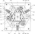
图1所示为本发明较佳实施例的六自由度精密定位平台主视图。Fig. 1 is a front view of a six-degree-of-freedom precision positioning platform of a preferred embodiment of the present invention.
图2所示为图1中六自由度精密定位平台沿A-A的旋转剖视图。Fig. 2 is a rotating sectional view along A-A of the six-degree-of-freedom precision positioning platform in Fig. 1 .
图3所示为本发明较佳实施例中水平调节平台的结构示意图。Fig. 3 is a schematic structural diagram of the horizontal adjustment platform in a preferred embodiment of the present invention.
图4所示为本发明较佳实施例中水平调节平台的结构原理图。Fig. 4 is a structural principle diagram of the horizontal adjustment platform in a preferred embodiment of the present invention.
图5所示为图1中六自由度精密定位平台沿B-B的旋转剖视图。Fig. 5 is a rotating sectional view along B-B of the six-degree-of-freedom precision positioning platform in Fig. 1 .
图6所示为本发明第二实施例中垂直调节平台的结构图。Fig. 6 is a structural diagram of the vertical adjustment platform in the second embodiment of the present invention.
具体实施方式Detailed ways
为了更了解本发明的技术内容,特举具体实施例并配合所附图式说明如下。In order to better understand the technical content of the present invention, specific embodiments are given together with the attached drawings for description as follows.
图1所示为本发明较佳实施例的六自由度精密定位平台主视图;图2所示为图1中沿A-A的旋转剖视图。请结合参考图1和图2。Fig. 1 is a front view of a six-degree-of-freedom precision positioning platform according to a preferred embodiment of the present invention; Fig. 2 is a rotational sectional view along A-A in Fig. 1 . Please refer to Figure 1 and Figure 2 together.
本实施例揭露的六自由度精密定位平台是用来承载印有用于曝光的图形的掩模版406,以将要曝光的图形定位到指定的位置。The six-degree-of-freedom precision positioning platform disclosed in this embodiment is used to carry the
六自由度精密定位平台的整体结构从上到下分为吸版台103、水平调节平台、垂向调节平台和底座101。The overall structure of the six-degree-of-freedom precision positioning platform is divided into a
吸版台103用来真空吸附掩模版406,以减少固定掩模版406时产生的应变。The suction table 103 is used to vacuum absorb the
水平调节平台用来承载物件,例如吸版台103。吸版台103包括水平基座104、水平输出平台102、三个具有放大功能并在圆周上均匀分布的旋转副柔性铰链机构(如图2所示的200)。水平调节平台的详细结构在后文中会详细描述。The horizontal adjustment platform is used to carry objects, such as the suction table 103 . The plate suction table 103 includes a
吸版台103通过螺钉或其他固定方式与水平调节平台的水平输出平台102刚性连接。The plate suction table 103 is rigidly connected with the
垂向调节平台包括垂向驱动器402、楔形块403、垂向柔性簧片405。The vertical adjustment platform includes a vertical driver 402 , a wedge block 403 , and a vertical flexible reed 405 .
垂向驱动器401通过垂向驱动器固定座401固定在底座101上;垂向柔性簧片405第一端通过螺钉与水平基座104刚性连接,第二端通过螺钉与底座101刚性连接。The vertical driver 401 is fixed on the base 101 through the vertical driver fixing base 401; the first end of the vertical flexible reed 405 is rigidly connected to the
底座101承载上述的垂向调节平台、水平调节平台和吸版台103,这三者通过底座101固定到其他粗调定位平台上,或其他分系统中。The base 101 carries the above-mentioned vertical adjustment platform, horizontal adjustment platform and plate suction table 103, and these three are fixed to other coarse adjustment positioning platforms or other subsystems through the
下面介绍本实施例中的垂向调节平台的工作原理。The working principle of the vertical adjustment platform in this embodiment will be introduced below.
垂向调节平台是由平均分布在360°上的三组调节机构组成,沿圆周平均分布,通过45°楔形调节机构将水平方向上的位移转化为垂直方向上的位移。The vertical adjustment platform is composed of three sets of adjustment mechanisms evenly distributed on 360°, which are evenly distributed along the circumference, and the displacement in the horizontal direction is converted into the displacement in the vertical direction through the 45° wedge-shaped adjustment mechanism.
垂向调节平台包括垂向驱动器402、楔形块403、垂向柔性簧片405。The vertical adjustment platform includes a vertical driver 402 , a wedge block 403 , and a vertical flexible reed 405 .
这里以其中一个调节机构为例进行说明,其他两组调节机构与之相同。垂向驱动器402a通过垂向驱动器固定座401a固定在底座101上,根据加载其上的电压沿水平方向产生位移变化。Here, one of the adjustment mechanisms is taken as an example for illustration, and the other two adjustment mechanisms are the same. The
楔形块403a的第一斜面与水平线的夹角为45°,楔形块403a固定在垂向驱动器402a上,并且可滑动地连接于楔形块引导座404a上。楔形块引导座404a固定在底座101上。楔形块403a受垂向驱动器402a驱动,沿X方向产生位移时在楔形块引导座404a上沿水平方向滑动。The included angle between the first slope of the
垂向柔性簧片405a的簧片为水平放置,因此,垂向柔性簧片405a适于让其两端连接的元件仅适合于垂向运动,而不会在X-Y平面运动。The reeds of the vertically
垂向柔性簧片405a第一端通过螺钉或其他固定方式与水平基座104刚性连接,第二端与底座101刚性连接。其中,垂向柔性簧片405a的第一端具有45°的第二斜面,与楔形块403a的第一斜面接触。当楔形块403a被垂向驱动器402a驱动而沿水平方向移动时,第一斜面和第二斜面相互运动,将水平方向上的移动转变为垂直方向上的移动。The first end of the vertical
楔形块403在楔形块引导座404的约束下,限制了楔形块403在X-Y平面内的运动,垂向柔性簧片由于自有的结构特点,其在X-Y平面内具有相当的刚性。所以在通过垂向调节平台调节Z轴、θx轴、θy轴的位置时,对水平基座104在X-Y平面内赋予了限制性的刚性引导。The wedge block 403 is constrained by the wedge block guide seat 404 to limit the movement of the wedge block 403 in the X-Y plane, and the vertical flexible reed has considerable rigidity in the X-Y plane due to its own structural characteristics. Therefore, when the positions of the Z axis, θx axis, and θy axis are adjusted by the vertical adjustment platform, a restrictive rigid guidance is given to the
由于第一斜面和第二斜面的角度均为45°,因此位移转化比为1:1。本领域具有通常知识者可以推理到,若想要达到其他位移转化比,只需要调整第一斜面和第二斜面与水平线的夹角即可。Since the angles of the first slope and the second slope are both 45°, the displacement conversion ratio is 1:1. Those skilled in the art can deduce that, to achieve other displacement conversion ratios, it is only necessary to adjust the included angles between the first slope and the second slope and the horizontal line.
图3所示为本发明较佳实施例中水平调节平台的结构示意图。Fig. 3 is a schematic structural diagram of the horizontal adjustment platform in a preferred embodiment of the present invention.
请结合参考图1和图3,在水平调节平台中,水平输出平台102固定连接吸版台103,并通过三组旋转副柔性铰链机构与水平基座104连接。三组旋转副柔性铰链机构沿圆周平均分布。Please refer to FIG. 1 and FIG. 3 together. In the horizontal adjustment platform, the
这里以其中一个旋转副柔性铰链机构为例进行说明,其他两组旋转副柔性铰链机构与之相同。Here, one of the swivel pair flexible hinge mechanisms is taken as an example for illustration, and the other two swivel pair flexible hinge mechanisms are the same.
旋转副柔性铰链机构200a包括旋转副柔性铰链205a、水平向驱动器203a和水平向驱动器支架202a组成。The swivel joint flexible hinge mechanism 200a includes a swivel joint
旋转副柔性铰链205a一端可转动地连接水平基座104,另一端可转动地连接水平输出平台102。One end of the swivel joint
水平向驱动器203a通过水平向驱动器支架202固定在水平基座104上,其一端顶住旋转副柔性铰链205a的凸台206a,并保持一定的预紧力。The
水平向驱动器203a根据其上电压的不同驱动旋转副柔性铰链205a的凸台206a沿f方向产生位移。The
在本实施例中采用垂向驱动器和水平向驱动器可以采用压电驱动器,也可以采用旋转电机加丝杠或其它的驱动方式。In this embodiment, the vertical driver and the horizontal driver may be piezoelectric drivers, or rotating motors plus screw or other driving methods may be used.
图4所示为本发明较佳实施例中水平调节平台的结构原理图。Fig. 4 is a structural principle diagram of the horizontal adjustment platform in a preferred embodiment of the present invention.
旋转副柔性铰链205a包括303a,连杆303a可转动地连接于杠杆302a的一端,杠杆302a的另一端可转动地链接在水平基座104上。The swivel joint
杠杆302a上具有凸台206a,凸台206a将杠杆302a分为长度为R1和R2两段。水平向驱动器203a顶住凸台206a,用以驱动凸台206a沿f方向移动。The
根据杠杆原理可知,在圆周每隔120°方向上的水平向驱动器230a的微位移经过旋转副柔性铰链205放大,其放大比RT=(1+R1/R2)。According to the principle of leverage, the micro-displacement of the horizontal driver 230a in every 120° direction of the circumference is amplified by the rotary joint flexible hinge 205, and the amplification ratio RT =(1+R1 /R2 ).
根据平面机构自由度计算公式F=3n-2p1-ph(其中F为自由度,n为机构中活动构件的数目、p1为平面低副数目、p2为平面高副数目)可知,水平调节平台的自由度为3。According to the calculation formula of degree of freedom of planar mechanism F=3n-2p1 -ph (wherein F is the degree of freedom, n is the number of movable components in the mechanism, p1 is the number of plane low pairs, and p2 is the number of plane high pairs), it can be seen that, The horizontal adjustment platform has 3 degrees of freedom.
水平调节平台可与垂向调节平台一同对吸版台103进行调整,也可独立于垂向调节平台在X、Y、θz三个方向上进行调节。由于水平调节平台采用了旋转副柔性铰链205,可以保证水平调节平台在Z方向上具有较强的刚性。The horizontal adjustment platform can adjust the plate suction table 103 together with the vertical adjustment platform, and can also be adjusted independently of the vertical adjustment platform in the three directions of X, Y, and θz. Since the horizontal adjustment platform adopts the swivel joint flexible hinge 205, it can ensure that the horizontal adjustment platform has strong rigidity in the Z direction.
本实施例中,水平调节平台还包括三个水平向位移传感器204a、204b和204c,通过传感器支架201固定在水平基座104上来实时检测水平输出平台102的位置。将三个水平向位移传感器204a、204b和204c的位移信号反馈至控制器(图未示)中,就可以形成闭环反馈。通过控制三个水平向驱动器203a、203b和203c的输出,可以精确调整水平输出平台102在X、Y、θz方向上位置和运动,实现需要的定位和精度。In this embodiment, the horizontal adjustment platform further includes three
另外,垂向调节平台还包括三个垂向位移传感器501a、501b(另一传感器未绘出),请参考图5。In addition, the vertical adjustment platform further includes three
垂向位移传感器501a通过垂向位移传感器固定座502a固定在底座101上,与楔形块403a尽量靠近,以实时测量水平基座104的垂向位置。The
将三个垂向位移传感器501a、501b和501c的位移信号反馈至控制器中,就可以形成闭环反馈,通过控制三个垂向驱动器401a、401b和401c的输出,可以精确调整水平基座104在X、Y、θz方向上位置和运动,实现需要的定位和精度。By feeding back the displacement signals of the three
由上述结构可见,本例中的定位平台具有在X轴、Y轴、Z轴、θx轴、θy轴、θz轴方向上的调节功能,可实现六个自由度的精密调节和定位,满足了多自由度的调节和定位需求。It can be seen from the above structure that the positioning platform in this example has adjustment functions in the directions of X-axis, Y-axis, Z-axis, θx-axis, θy-axis, and θz-axis, and can realize precise adjustment and positioning of six degrees of freedom, satisfying the Multi-degree-of-freedom adjustment and positioning requirements.
图6所示为本发明第二实施例中垂直调节平台的结构图。Fig. 6 is a structural diagram of the vertical adjustment platform in the second embodiment of the present invention.
本实施例将图4中柔性簧片和楔形机构构成的垂向调节平台换成垂向驱动器602a的驱动方向为沿垂向移动,直接驱动柔性簧片603a,达到调节整个定位台Z轴、θx轴和θy轴三个自由度的目的。在满足垂向安装空间的前提下,可保证定位平台结构更为简单,保证运动传递的无摩擦,免润滑、高精度。In this embodiment, the vertical adjustment platform formed by the flexible reed and the wedge-shaped mechanism in Fig. 4 is replaced by the driving direction of the
本实施例中的水平调节平台和垂向调节平台之间仅通过楔形机构和垂向柔性簧片连接,使得整个定位平台结构简单,降低了制造难度,提高了装配精度。The horizontal adjustment platform and the vertical adjustment platform in this embodiment are only connected by a wedge mechanism and a vertical flexible spring, so that the structure of the whole positioning platform is simple, the manufacturing difficulty is reduced, and the assembly accuracy is improved.
虽然本发明已以较佳实施例揭露如上,然其并非用以限定本发明。本发明所属技术领域中具有通常知识者,在不脱离本发明的精神和范围内,当可作各种的更动与润饰。因此,本发明的保护范围当视权利要求书所界定者为准。Although the present invention has been disclosed above with preferred embodiments, it is not intended to limit the present invention. Those skilled in the art of the present invention can make various changes and modifications without departing from the spirit and scope of the present invention. Therefore, the scope of protection of the present invention should be defined by the claims.
Claims (11)
Priority Applications (1)
| Application Number | Priority Date | Filing Date | Title |
|---|---|---|---|
| CN2009100470311ACN101488371B (en) | 2009-03-04 | 2009-03-04 | Precise positioning platform with six freedom of motion |
Applications Claiming Priority (1)
| Application Number | Priority Date | Filing Date | Title |
|---|---|---|---|
| CN2009100470311ACN101488371B (en) | 2009-03-04 | 2009-03-04 | Precise positioning platform with six freedom of motion |
Publications (2)
| Publication Number | Publication Date |
|---|---|
| CN101488371Atrue CN101488371A (en) | 2009-07-22 |
| CN101488371B CN101488371B (en) | 2010-12-29 |
Family
ID=40891206
Family Applications (1)
| Application Number | Title | Priority Date | Filing Date |
|---|---|---|---|
| CN2009100470311AActiveCN101488371B (en) | 2009-03-04 | 2009-03-04 | Precise positioning platform with six freedom of motion |
Country Status (1)
| Country | Link |
|---|---|
| CN (1) | CN101488371B (en) |
Cited By (27)
| Publication number | Priority date | Publication date | Assignee | Title |
|---|---|---|---|---|
| CN102247211A (en)* | 2011-03-24 | 2011-11-23 | 北京天智航医疗科技股份有限公司 | Surgical instrument fixing device |
| CN101750885B (en)* | 2010-01-06 | 2011-12-14 | 天津大学 | Two-degree of freedom precise positioning work table |
| CN101726997B (en)* | 2009-12-11 | 2011-12-28 | 天津大学 | Six-freedom-degree precision positioning table for nano-imprint lithography system |
| CN101769730B (en)* | 2010-01-22 | 2012-07-25 | 西安工业大学 | Workpiece leveling and centering device |
| CN102759995A (en)* | 2012-06-13 | 2012-10-31 | 西北工业大学 | Spatial six-dimensional computer input device |
| CN102969031A (en)* | 2012-12-12 | 2013-03-13 | 中国科学院光电技术研究所 | Z-theta x-theta y three-degree-of-freedom nanoscale precision two-body workbench |
| CN103376664A (en)* | 2012-04-20 | 2013-10-30 | 上海微电子装备有限公司 | Reticle stage with station switching function |
| CN103386629A (en)* | 2013-07-16 | 2013-11-13 | 山东理工大学 | Device for fine adjustment of posture |
| CN103680641A (en)* | 2013-12-06 | 2014-03-26 | 华南理工大学 | Fix-freedom-degree precise positioning platform based on flexible structure |
| CN104111525A (en)* | 2014-06-30 | 2014-10-22 | 北京航天发射技术研究所 | Beam splitter prism assembly used for photoelectric collimation of collimator |
| CN105723608A (en)* | 2013-10-18 | 2016-06-29 | 上海交通大学 | Piezo ceramic planar motor and driving method thereof |
| CN106141654A (en)* | 2015-03-26 | 2016-11-23 | 上海微电子装备有限公司 | A kind of regulation locking device |
| CN104197982B (en)* | 2014-08-26 | 2017-05-24 | 昆山迈致治具科技有限公司 | Six-axis jig |
| CN106932878A (en)* | 2015-12-31 | 2017-07-07 | 上海微电子装备有限公司 | A kind of six-degree-of-freedom adjusting |
| CN107145164A (en)* | 2017-05-19 | 2017-09-08 | 广东工业大学 | A kind of grand micro- compound locating platform of vertical movement |
| CN107741621A (en)* | 2017-12-05 | 2018-02-27 | 中国科学院苏州生物医学工程技术研究所 | Five degrees of freedom precision adjustment table |
| CN107870405A (en)* | 2017-12-05 | 2018-04-03 | 中国科学院苏州生物医学工程技术研究所 | Multi-degree-of-freedom optical precision adjustment stage |
| WO2018076339A1 (en)* | 2016-10-31 | 2018-05-03 | 中国科学院长春光学精密机械与物理研究所 | Six-degree-of-freedom microdisplacement regulating device for optical element, projection objective and lithography machine |
| CN108036808A (en)* | 2017-12-04 | 2018-05-15 | 兰州空间技术物理研究所 | A kind of high-precision tilt angle Control experiment platform |
| CN110666756A (en)* | 2019-10-21 | 2020-01-10 | 湖北汽车工业学院 | A two-dimensional precision micro-movement worktable with double displacement and using method |
| CN110815613A (en)* | 2019-12-13 | 2020-02-21 | 中国工程物理研究院机械制造工艺研究所 | A nano-feed assembly for ultra-precision flying-cutting machine tools |
| CN113363194A (en)* | 2021-06-03 | 2021-09-07 | 广东工业大学 | Heavy-load fine-adjustment flat positioning platform based on micro LED chip array transfer |
| CN114123851A (en)* | 2021-12-03 | 2022-03-01 | 散裂中子源科学中心 | A six-degree-of-freedom attitude adjustment platform |
| CN114114585A (en)* | 2021-12-06 | 2022-03-01 | 中国科学院光电技术研究所 | A motion table for a six-degree-of-freedom compliant mechanism of a lens |
| CN114670083A (en)* | 2022-04-24 | 2022-06-28 | 西安交通大学 | Bearing platform for non-contact driving three-rotational-freedom-degree displacement output |
| CN114952743A (en)* | 2022-06-28 | 2022-08-30 | 郑州机械研究所有限公司 | Six-degree-of-freedom self-adaptive displacement platform |
| CN115629456A (en)* | 2022-10-18 | 2023-01-20 | 中国科学院合肥物质科学研究院 | A six-degree-of-freedom optical component precision control platform |
Families Citing this family (1)
| Publication number | Priority date | Publication date | Assignee | Title |
|---|---|---|---|---|
| TW201508294A (en)* | 2013-08-26 | 2015-03-01 | Chiuan Yan Technology Co Ltd | Bed type detection mechanism for detecting alignment and conductivity of optical element |
- 2009
- 2009-03-04CNCN2009100470311Apatent/CN101488371B/enactiveActive
Cited By (39)
| Publication number | Priority date | Publication date | Assignee | Title |
|---|---|---|---|---|
| CN101726997B (en)* | 2009-12-11 | 2011-12-28 | 天津大学 | Six-freedom-degree precision positioning table for nano-imprint lithography system |
| CN101750885B (en)* | 2010-01-06 | 2011-12-14 | 天津大学 | Two-degree of freedom precise positioning work table |
| CN101769730B (en)* | 2010-01-22 | 2012-07-25 | 西安工业大学 | Workpiece leveling and centering device |
| CN102247211A (en)* | 2011-03-24 | 2011-11-23 | 北京天智航医疗科技股份有限公司 | Surgical instrument fixing device |
| CN103376664A (en)* | 2012-04-20 | 2013-10-30 | 上海微电子装备有限公司 | Reticle stage with station switching function |
| CN103376664B (en)* | 2012-04-20 | 2016-02-03 | 上海微电子装备有限公司 | A kind of mask platform with Switch of working position function |
| CN102759995A (en)* | 2012-06-13 | 2012-10-31 | 西北工业大学 | Spatial six-dimensional computer input device |
| CN102759995B (en)* | 2012-06-13 | 2015-06-24 | 西北工业大学 | Spatial six-dimensional computer input device |
| CN102969031B (en)* | 2012-12-12 | 2015-06-17 | 中国科学院光电技术研究所 | Z-theta x-theta y three-degree-of-freedom nanoscale precision two-body workbench |
| CN102969031A (en)* | 2012-12-12 | 2013-03-13 | 中国科学院光电技术研究所 | Z-theta x-theta y three-degree-of-freedom nanoscale precision two-body workbench |
| CN103386629B (en)* | 2013-07-16 | 2015-07-01 | 山东理工大学 | Device for fine adjustment of posture |
| CN103386629A (en)* | 2013-07-16 | 2013-11-13 | 山东理工大学 | Device for fine adjustment of posture |
| US10491140B2 (en) | 2013-10-18 | 2019-11-26 | Shanghai Jiaotong University | Piezo ceramic planar motor and driving method thereof |
| CN105723608A (en)* | 2013-10-18 | 2016-06-29 | 上海交通大学 | Piezo ceramic planar motor and driving method thereof |
| CN103680641A (en)* | 2013-12-06 | 2014-03-26 | 华南理工大学 | Fix-freedom-degree precise positioning platform based on flexible structure |
| CN104111525A (en)* | 2014-06-30 | 2014-10-22 | 北京航天发射技术研究所 | Beam splitter prism assembly used for photoelectric collimation of collimator |
| CN104111525B (en)* | 2014-06-30 | 2017-03-01 | 北京航天发射技术研究所 | Amici prism assembly for pointing instrumentation photoelectricity collimation |
| CN104197982B (en)* | 2014-08-26 | 2017-05-24 | 昆山迈致治具科技有限公司 | Six-axis jig |
| CN106141654A (en)* | 2015-03-26 | 2016-11-23 | 上海微电子装备有限公司 | A kind of regulation locking device |
| CN106932878A (en)* | 2015-12-31 | 2017-07-07 | 上海微电子装备有限公司 | A kind of six-degree-of-freedom adjusting |
| WO2018076339A1 (en)* | 2016-10-31 | 2018-05-03 | 中国科学院长春光学精密机械与物理研究所 | Six-degree-of-freedom microdisplacement regulating device for optical element, projection objective and lithography machine |
| CN107145164A (en)* | 2017-05-19 | 2017-09-08 | 广东工业大学 | A kind of grand micro- compound locating platform of vertical movement |
| CN108036808A (en)* | 2017-12-04 | 2018-05-15 | 兰州空间技术物理研究所 | A kind of high-precision tilt angle Control experiment platform |
| CN107741621A (en)* | 2017-12-05 | 2018-02-27 | 中国科学院苏州生物医学工程技术研究所 | Five degrees of freedom precision adjustment table |
| CN107870405A (en)* | 2017-12-05 | 2018-04-03 | 中国科学院苏州生物医学工程技术研究所 | Multi-degree-of-freedom optical precision adjustment stage |
| CN107870405B (en)* | 2017-12-05 | 2023-08-25 | 中国科学院苏州生物医学工程技术研究所 | Multi-degree-of-freedom optical precision adjustment table |
| CN107741621B (en)* | 2017-12-05 | 2023-08-22 | 中国科学院苏州生物医学工程技术研究所 | Five-degree-of-freedom precise adjusting table |
| CN110666756A (en)* | 2019-10-21 | 2020-01-10 | 湖北汽车工业学院 | A two-dimensional precision micro-movement worktable with double displacement and using method |
| CN110815613A (en)* | 2019-12-13 | 2020-02-21 | 中国工程物理研究院机械制造工艺研究所 | A nano-feed assembly for ultra-precision flying-cutting machine tools |
| CN113363194B (en)* | 2021-06-03 | 2022-09-27 | 广东工业大学 | Heavy-load fine-adjustment flat positioning platform based on micro LED chip array transfer |
| CN113363194A (en)* | 2021-06-03 | 2021-09-07 | 广东工业大学 | Heavy-load fine-adjustment flat positioning platform based on micro LED chip array transfer |
| CN114123851A (en)* | 2021-12-03 | 2022-03-01 | 散裂中子源科学中心 | A six-degree-of-freedom attitude adjustment platform |
| CN114114585A (en)* | 2021-12-06 | 2022-03-01 | 中国科学院光电技术研究所 | A motion table for a six-degree-of-freedom compliant mechanism of a lens |
| CN114114585B (en)* | 2021-12-06 | 2023-05-26 | 中国科学院光电技术研究所 | Six-freedom-degree compliant mechanism movement table for lenses |
| CN114670083A (en)* | 2022-04-24 | 2022-06-28 | 西安交通大学 | Bearing platform for non-contact driving three-rotational-freedom-degree displacement output |
| CN114670083B (en)* | 2022-04-24 | 2023-03-10 | 西安交通大学 | Bearing platform for non-contact driving three-rotational-freedom-degree displacement output |
| CN114952743A (en)* | 2022-06-28 | 2022-08-30 | 郑州机械研究所有限公司 | Six-degree-of-freedom self-adaptive displacement platform |
| CN115629456A (en)* | 2022-10-18 | 2023-01-20 | 中国科学院合肥物质科学研究院 | A six-degree-of-freedom optical component precision control platform |
| CN115629456B (en)* | 2022-10-18 | 2025-04-01 | 中国科学院合肥物质科学研究院 | A six-degree-of-freedom optical element precision control platform |
Also Published As
| Publication number | Publication date |
|---|---|
| CN101488371B (en) | 2010-12-29 |
Similar Documents
| Publication | Publication Date | Title |
|---|---|---|
| CN101488371B (en) | Precise positioning platform with six freedom of motion | |
| CN112096739B (en) | An air-floating guide rail type switchable rigid-flexible coupling motion platform | |
| CN101609193B (en) | Movable optical element adjusting and positioning device | |
| CN101334591A (en) | Leveling and focusing mechanism with large stroke adjustment function | |
| CN100461365C (en) | High-precision silicon wafer stage and its positioning method | |
| CN101436436A (en) | Accurate one-dimensional rotary and two-dimensional tilting table | |
| CN1839348A (en) | High-resolution dynamic positioning mechanism for sample detection and processing | |
| CN106737646A (en) | It is capable of achieving translation and the Three Degree Of Freedom Piezoelectric Driving adjusting means and method that rotate | |
| CN211087931U (en) | Three-degree-of-freedom micro-nano positioning platform | |
| CN104536073A (en) | Grating ruling tool initiative adjusting device having abbe error correcting function | |
| CN1562579A (en) | High precision flexible parallel robot with six degreed of freedom and large travel | |
| JP2591844B2 (en) | Coarse positioning device | |
| CN103197416B (en) | Double-freedom-degree high-speed parallel scan platform and perpendicularity error calibrating method | |
| CN103176270B (en) | Two-degree-of-freedom high-speed parallel scanning platform and perpendicularity error calibration method thereof | |
| CN110905909A (en) | A plane three-degree-of-freedom precision positioning platform, its use method and control method | |
| CN2932619Y (en) | High-precision silicon table | |
| CN1896875A (en) | Photoetching equipment | |
| US11143529B2 (en) | Cantilever linear motion reference device employing two-layer air suspension | |
| CN114123851A (en) | A six-degree-of-freedom attitude adjustment platform | |
| CN117348349A (en) | Plane rotating mechanism, micro-motion platform and macro-micro motion platform for wafer photoetching | |
| CN106500587A (en) | A kind of grand micro- precise focusing device of white light interferometer Z axis and its focus adjustment method | |
| CA2603643A1 (en) | Microscope stage with flexural axis | |
| CN101441319B (en) | Large-range plane three-freedom degree precision fine motion device and control method thereof | |
| CN201335912Y (en) | Large-stroke planar 3-DOF precision micro-actuator | |
| CN113630036A (en) | Device and method for improving motion resolution of standing wave type piezoelectric ultrasonic motor |
Legal Events
| Date | Code | Title | Description |
|---|---|---|---|
| C06 | Publication | ||
| PB01 | Publication | ||
| C10 | Entry into substantive examination | ||
| SE01 | Entry into force of request for substantive examination | ||
| C14 | Grant of patent or utility model | ||
| GR01 | Patent grant | ||
| CP01 | Change in the name or title of a patent holder | Address after:201203 Zhangjiang High Tech Park, Shanghai, Zhang Dong Road, No. 1525 Patentee after:SHANGHAI MICRO ELECTRONICS EQUIPMENT (GROUP) Co.,Ltd. Address before:201203 Zhangjiang High Tech Park, Shanghai, Zhang Dong Road, No. 1525 Patentee before:SHANGHAI MICRO ELECTRONICS EQUIPMENT Co.,Ltd. | |
| CP01 | Change in the name or title of a patent holder | ||
| TR01 | Transfer of patent right | Effective date of registration:20250710 Address after:3 / F, building 19, building 8, No. 498, GuoShouJing Road, China (Shanghai) pilot Free Trade Zone, Pudong New Area, Shanghai, 201203 Patentee after:Shanghai Xinshang Microelectronics Technology Co.,Ltd. Country or region after:China Address before:201203 Zhangjiang High Tech Park, Shanghai, Zhang Dong Road, No. 1525 Patentee before:SHANGHAI MICRO ELECTRONICS EQUIPMENT (GROUP) Co.,Ltd. Country or region before:China | |
| TR01 | Transfer of patent right |