CN101485910B - Contrast container holder and method to fill syringes - Google Patents
Contrast container holder and method to fill syringesDownload PDFInfo
- Publication number
- CN101485910B CN101485910BCN2009100050620ACN200910005062ACN101485910BCN 101485910 BCN101485910 BCN 101485910BCN 2009100050620 ACN2009100050620 ACN 2009100050620ACN 200910005062 ACN200910005062 ACN 200910005062ACN 101485910 BCN101485910 BCN 101485910B
- Authority
- CN
- China
- Prior art keywords
- syringe
- injector
- contrast
- fill
- container
- Prior art date
- Legal status (The legal status is an assumption and is not a legal conclusion. Google has not performed a legal analysis and makes no representation as to the accuracy of the status listed.)
- Expired - Fee Related
Links
- 238000000034methodMethods0.000titleclaimsabstractdescription64
- 239000002872contrast mediaSubstances0.000claimsdescription30
- 239000012530fluidSubstances0.000claimsdescription28
- 230000008569processEffects0.000claimsdescription14
- 238000002347injectionMethods0.000claimsdescription10
- 239000007924injectionSubstances0.000claimsdescription10
- 238000005429filling processMethods0.000claimsdescription6
- 238000007599dischargingMethods0.000claimsdescription2
- 238000010438heat treatmentMethods0.000description9
- 238000005273aerationMethods0.000description7
- 239000000463materialSubstances0.000description6
- 238000005516engineering processMethods0.000description5
- 238000013461designMethods0.000description3
- 238000003384imaging methodMethods0.000description3
- 229920003023plasticPolymers0.000description3
- 238000002583angiographyMethods0.000description2
- 229940039231contrast mediaDrugs0.000description2
- 238000007689inspectionMethods0.000description2
- 230000001360synchronised effectEffects0.000description2
- 229910000831SteelInorganic materials0.000description1
- XAGFODPZIPBFFR-UHFFFAOYSA-NaluminiumChemical compound[Al]XAGFODPZIPBFFR-UHFFFAOYSA-N0.000description1
- 229910052782aluminiumInorganic materials0.000description1
- 230000008901benefitEffects0.000description1
- 230000015572biosynthetic processEffects0.000description1
- 230000036760body temperatureEffects0.000description1
- 230000008859changeEffects0.000description1
- 238000004891communicationMethods0.000description1
- 238000003745diagnosisMethods0.000description1
- 238000009792diffusion processMethods0.000description1
- 238000001802infusionMethods0.000description1
- 230000003993interactionEffects0.000description1
- 238000011835investigationMethods0.000description1
- 238000004519manufacturing processMethods0.000description1
- 238000009206nuclear medicineMethods0.000description1
- 230000003287optical effectEffects0.000description1
- 238000012856packingMethods0.000description1
- 239000004033plasticSubstances0.000description1
- 238000012545processingMethods0.000description1
- 238000011084recoveryMethods0.000description1
- 238000007634remodelingMethods0.000description1
- 230000004044responseEffects0.000description1
- 239000000243solutionSubstances0.000description1
- 239000010959steelSubstances0.000description1
- 238000003860storageMethods0.000description1
- 239000000126substanceSubstances0.000description1
- 230000007704transitionEffects0.000description1
Images


Classifications
- A—HUMAN NECESSITIES
- A61—MEDICAL OR VETERINARY SCIENCE; HYGIENE
- A61M—DEVICES FOR INTRODUCING MEDIA INTO, OR ONTO, THE BODY; DEVICES FOR TRANSDUCING BODY MEDIA OR FOR TAKING MEDIA FROM THE BODY; DEVICES FOR PRODUCING OR ENDING SLEEP OR STUPOR
- A61M5/00—Devices for bringing media into the body in a subcutaneous, intra-vascular or intramuscular way; Accessories therefor, e.g. filling or cleaning devices, arm-rests
- A61M5/007—Devices for bringing media into the body in a subcutaneous, intra-vascular or intramuscular way; Accessories therefor, e.g. filling or cleaning devices, arm-rests for contrast media
- A—HUMAN NECESSITIES
- A61—MEDICAL OR VETERINARY SCIENCE; HYGIENE
- A61M—DEVICES FOR INTRODUCING MEDIA INTO, OR ONTO, THE BODY; DEVICES FOR TRANSDUCING BODY MEDIA OR FOR TAKING MEDIA FROM THE BODY; DEVICES FOR PRODUCING OR ENDING SLEEP OR STUPOR
- A61M5/00—Devices for bringing media into the body in a subcutaneous, intra-vascular or intramuscular way; Accessories therefor, e.g. filling or cleaning devices, arm-rests
- A61M5/14—Infusion devices, e.g. infusing by gravity; Blood infusion; Accessories therefor
- A61M5/142—Pressure infusion, e.g. using pumps
- A61M5/145—Pressure infusion, e.g. using pumps using pressurised reservoirs, e.g. pressurised by means of pistons
- A61M5/1452—Pressure infusion, e.g. using pumps using pressurised reservoirs, e.g. pressurised by means of pistons pressurised by means of pistons
- A61M5/14546—Front-loading type injectors
- A—HUMAN NECESSITIES
- A61—MEDICAL OR VETERINARY SCIENCE; HYGIENE
- A61M—DEVICES FOR INTRODUCING MEDIA INTO, OR ONTO, THE BODY; DEVICES FOR TRANSDUCING BODY MEDIA OR FOR TAKING MEDIA FROM THE BODY; DEVICES FOR PRODUCING OR ENDING SLEEP OR STUPOR
- A61M2209/00—Ancillary equipment
- A61M2209/08—Supports for equipment
- A61M2209/082—Mounting brackets, arm supports for equipment
- A—HUMAN NECESSITIES
- A61—MEDICAL OR VETERINARY SCIENCE; HYGIENE
- A61M—DEVICES FOR INTRODUCING MEDIA INTO, OR ONTO, THE BODY; DEVICES FOR TRANSDUCING BODY MEDIA OR FOR TAKING MEDIA FROM THE BODY; DEVICES FOR PRODUCING OR ENDING SLEEP OR STUPOR
- A61M5/00—Devices for bringing media into the body in a subcutaneous, intra-vascular or intramuscular way; Accessories therefor, e.g. filling or cleaning devices, arm-rests
- A61M5/14—Infusion devices, e.g. infusing by gravity; Blood infusion; Accessories therefor
- A61M5/142—Pressure infusion, e.g. using pumps
- A61M5/145—Pressure infusion, e.g. using pumps using pressurised reservoirs, e.g. pressurised by means of pistons
- A61M5/1452—Pressure infusion, e.g. using pumps using pressurised reservoirs, e.g. pressurised by means of pistons pressurised by means of pistons
- A61M5/14566—Pressure infusion, e.g. using pumps using pressurised reservoirs, e.g. pressurised by means of pistons pressurised by means of pistons with a replaceable reservoir for receiving a piston rod of the pump
- A—HUMAN NECESSITIES
- A61—MEDICAL OR VETERINARY SCIENCE; HYGIENE
- A61M—DEVICES FOR INTRODUCING MEDIA INTO, OR ONTO, THE BODY; DEVICES FOR TRANSDUCING BODY MEDIA OR FOR TAKING MEDIA FROM THE BODY; DEVICES FOR PRODUCING OR ENDING SLEEP OR STUPOR
- A61M5/00—Devices for bringing media into the body in a subcutaneous, intra-vascular or intramuscular way; Accessories therefor, e.g. filling or cleaning devices, arm-rests
- A61M5/178—Syringes
- A61M5/1782—Devices aiding filling of syringes in situ
Landscapes
- Health & Medical Sciences (AREA)
- Vascular Medicine (AREA)
- Engineering & Computer Science (AREA)
- Anesthesiology (AREA)
- Biomedical Technology (AREA)
- Heart & Thoracic Surgery (AREA)
- Hematology (AREA)
- Life Sciences & Earth Sciences (AREA)
- Animal Behavior & Ethology (AREA)
- General Health & Medical Sciences (AREA)
- Public Health (AREA)
- Veterinary Medicine (AREA)
- Infusion, Injection, And Reservoir Apparatuses (AREA)
- Apparatus For Radiation Diagnosis (AREA)
Abstract
Description
The application is that international filing date is that December in 2004 9 days, national applications number are 200480039611.1, denomination of invention is divided an application for the application for a patent for invention of " contrast container holder and the method for filling syringe ".
Technical field
The present invention relates to be used for to the fluidic injector of patient infusion.
Background technology
In many medical environments, medical fluid is injected in patient's body during diagnosis or treatment.Instance is contrast agent to be injected in patient's body with any diagnosing image or the treatment that improve the automatic injector that optical imagery, nuclear medicine, CT, angiography, magnetic resonance or ultrasonic imaging or working power promote use.
The injector that is suitable for these and similar application must be used the syringe of relatively large volume and can produce relatively large flow and injection pressure usually.For this reason, the injector of these application is normally vehicularized and comprise big high-quality injector motor and drive chain.In order to be easy to use, motor and drive chain are contained in the injection head usually, and this arm of being installed by floor, wall or ceiling supports.
Injection head pivotally is installed on the arm usually, like this head can be inclined upwardly (barrel tip is on the syringe remainder) so that use the fluid filled syringe and downwards (barrel tip is under the syringe remainder) be used for injecting.Tilt head is convenient to during filling, from syringe, remove air by this way, reduces the injection process air and is injected into intravital probability.Yet all of a sudden injecting air into the intravital potential probability of patient still becomes serious security consideration.
Except the injection head of top discussion, many injector comprise that independent control station is with the control injector.Control station generally comprises programmable circuit, this circuit can be used to injector automatically, the control of programming, the operation of injector is predictable and for example the operation of scanning device or imaging device is synchronous with other equipment potentially like this.
A specific operation sequence of being carried out by injecting systems is to fill syringe with contrast agent.This to-fill procedure of power injector needs the operator to make with the hands usually.One held contrast container is near injector, thereby another hand operated injector controller is filled syringe with the withdrawal piston.Even can fill automatically in the injector of preset vol, when beginning automatic to-fill procedure at first, still need the operator to make with the hands.
Therefore, have such needs, thereby injecting program operator at least one hands in the whole operation process of filling syringe of promptly simplifying in the power injector can be carried out other actions.
When filling syringe, to-fill procedure possibly go wrong once in a while, if because carry out too fast, contrast agent can be inflated, if perhaps carry out too slow, accomplish this program and may expend the too many time.Therefore, based on the air that possibly occur in contrast agent and the filling pipe, there is the contrast agent peak filling rate that to avoid during filling, making aeration.Though this speed can be programmed in injector and use automatically, the operator will keep watch on the filling of syringe usually further to reduce the probability of aeration.Need a kind of to-fill procedure to allow accessible maximum filling speed when in filling pipe, air occurring, fill syringe with contrast fluid.
Summary of the invention
Above-mentioned those needs pointed out of traditional injector system and other problems can be allowed to exempt from hands and fill the embodiment of the invention of syringe and in filling process, can not make aeration just can carry out the embodiment of the invention solution of to-fill procedure.
One aspect of the present invention relates to a kind of contrast media injector system; Comprise injector and the contrast container holder that is connected with injector; Wherein said contrast container holder is configured to contrast container is remained on fixed basically position, simultaneously said injector perpendicular orientation.
Another aspect of the present invention relates to a kind of method that is used in the contrast media injector system with the filling pipe that syringe is connected to contrast agent, carrying out to-fill procedure.According to this aspect; From fill pipe, discharge all air basically, after this, fill syringe with the first rate that prevents aeration; And wherein said first rate is faster than second speed, and this second speed is not in advance from filling the maximum fill rate of bank of tubes when going out air.
Another aspect of the present invention relates to a kind of method of in syringe to-fill procedure process, changing contrast container.According to this aspect, when first contrast container basic overhead the time, suspend the syringe to-fill procedure of syringe, and replace first contrast container with second contrast container.Next; From be connected the filling pipe between the syringe and second contrast container, discharge all air basically; After this; Continue to fill syringe from second contrast container with the first rate that prevents aeration, wherein said first rate is faster than second speed, and this second speed is not in advance from filling the maximum fill rate of bank of tubes when going out air.
Description of drawings
Fig. 1 shows the perspective view of injector in accordance with the principles of the present invention, comprise unit head, control station and (under the lid) power pack, and syringe, pressure jacket, heating blanket and air detecting module is taken away.
Fig. 2 shows the perspective view of Fig. 1 injector unit head, and wherein pressure jacket, syringe and heating blanket are mounted thereto, illustrates in greater detail unit head display, manual controller and support arm mounting.
Fig. 3 shows contrast container holder according to an embodiment of the invention.
Fig. 4 shows contrast container holder according to another embodiment of the present invention.
Fig. 5 shows contrast container holder according to another embodiment of the present invention.
Fig. 6 shows contrast container holder according to yet another embodiment of the invention.
Fig. 7 shows and uses injector system to fill the flow chart of the illustrative methods of syringe.
The specific embodiment
Motorized injection systems
With reference to figure 1,injector 20 according to the present invention comprises various functional parts, forexample unit head 22,control station 24 and power pack 26 (it is inboard to be installed in lid).Syringe 36 (Fig. 2) is installed in thepanel 28 ofunit head 22 ofinjector 20; Use various injector controllers to fill syringe with the contrast agent that for example is used for CT, angiography or other processing, contrast agent is injecting object under operator's the investigation or under the control in pre-programmed then.
With reference now to Fig. 2; In operation; Syringe 36 is installed on theunit head 22 withpressure jacket 38, like thisunit head 22 inner motors can switch on in the tube ofsyringe 36 toward and away fromdischarge end 40mobile pistons 37 of syringe, thereby fromsyringe 36 discharge fluids or use the fluid filledsyringe.Pressure jacket 38 supports the wall unlikely damage under high injection pressure withprotection syringe 36 for the outer wall ofsyringe 36 provides.
Syringe 36 andpressure jacket 38 are processed by transparent plastic material, and the operator can see through this transparent plastic and observe any fluid or the air between thepiston 37 anddischarge end 40 in current position and the syringe of piston 37.Therefore; As stated, operator'sunit head 22 that can be inclined upwardly is filledsyringe 36 from fluid source and is visually kept watch on filling process simultaneously; Then injector is connected to the pipeline that leads to the patient; Simultaneously visually keep watch on fluidic level the syringe from pipeline and syringe air-out, a denier air is discharged from then, downward-sloping injector and begin fluid is injected object.
For the ease of this filling process and other operations that possibly in the target injection process, carry out,unit head 22 comprises manual motion controller, and the form of this controller is rotatable bar 29.Particularly,bar 29 can rotate on the rotating shaft ofunit head 22 inboards.Whenmanual control stick 29 was in its home position, as shown in Figure 2,unit head 22 did not produce the piston motion.Yet when manual control stick 29 during towardssyringe 36 rotation,unit head 22 produces piston motion forward, discharges fluid or air from syringe 36.Alternatively, when manual control stick 29 rotated away fromsyringe 36,unit head 22 produced reverse piston motion, with fluid or fills withair syringe 36.
Fluid in order to ensure injecting object roughly remains on body temperature, and the outer wall ofcontiguous pressure jacket 38 has been installed heating blanket 42.Heating blanket 42 comprises that the generation heat is to regulate the electric heater of the fluid temperature (F.T.) in the syringe 36.Heating blanket 42 is installed on thepost 44 that stretches out frompanel 28, keepsheating blanket 42 andpressure jacket 38 thermo-contacts.
Inunit head 22 rear ends are display lamps 46 (with light diffusion blanketing lid) of indication unit head state.
The further details of controlling example hardware and the software of the operation of injector system shown in Fig. 1 and 2 for example can be with reference to United States Patent(USP) No. 5,868,710, and this patent has transferred assignee of the present invention, and through reference its full content is incorporated into this.
Pan straddle
A particular operational program utilizing injector system to carry out usually is to fillsyringe 36 with contrast agent.This to-fill procedure of power injector need use operator's both hands usually.Proficiency is held in contrast container near the injector, thereby and another hand operated injector controller withdrawal piston is filled syringe.Even utilize the injector that can fill preset vol automatically, when beginning automatic to-fill procedure at first, still need the operator to make with the hands.Therefore, thus injecting program at least one hands of operator when filling syringe of need simplifying in the power injector can carry out other actions.
Particularly, an exemplary answer that solves these needs is to use the contrast container holder that is connected on a part ofinjector 22 and container is fixed on the direction that helps to fill syringe.
The material of this pan straddle can be to have any in the various suitable materials of rigidity of the common contrast container weight of enough supports.Preferably, said material comprises plastics, rustless steel, aluminum and some pottery.In these materials each also will enough tolerate moisture, chemical substance and temperature to allow easily to clean support through the whole bag of tricks.In addition, the material of support is such, and promptly it can not exceedingly destroy or damage contrast container, but possibly stand repeatedly still can work under the ballistic environment of various fiercenesses at it.
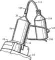
Fig. 3 shows the particular exemplary design that is used for contrast container holder; Yet those of ordinary skill should be appreciated that, can find out the design of other functional equivalents within the scope of the invention.Pan straddle has carriage 502,506, and it is connected with thepart 44 of injector housing and is suitable for keepingcontrast container 504, fillspipe 510 like this and can easily arrive whole contrast container.More specifically, Fig. 3 shows the pan straddle of two parts, and it has theupper bend arm 502 aroundcontrast container 504, andunderarm 506 is from following support vessels 504.Twoarms injector 22 to keepcontainer 504.
Exemplary support 502,506 is characterised in that open design, and it has only made things convenient for fixes and take offcontrast container 504 with a hands.Certainly, though the operator can make and with the hands insert and take offcontainer 504, this is optional.During to-fill procedure, when the operator must replace container, a hand operated was particularly useful.
Another feature of support 502,506 is that it makescontainer 504contiguous barrel tip 508 locate, and fillspipe 510 like this and can be bridged tocontainer 504 bottoms from syringe 36.Typical filling pipe is 8 inches long, and can consider other length if desired.
Contrast container holder 502,506 another is characterised in that wheninjector 22 roughly confirms direction when carrying out to-fill procedure, and it is towards fillingpipe 510 tilt containers 504.The United States Patent(USP) No. 5,868,710 that the front is integrated is described correct a kind of example system of confirming the injector direction in filling process in detail.
Though a series of inclination angle can be used for support 502,506, container can be not tilt so much so that contrast fluid spills towardsinjector 22, can not tilt too slightly so that fillpipe 510 to arrivecontainer 504 bottoms.Can not arrivecontainer 504 bottoms if fillpipe 510, then contrast fluid can not be removed fromcontainer 504 fully.
Though Fig. 3 has described the exemplary containers support 502,506 that is connected to heatingsheath 44, pan straddle 502,506 can be connected withinjector 22 through many modes.For example, the housing downside of injector can installed or be clipped in to support, perhaps even on the panel.In addition, support can be connected on the post that keeps heating blanket.In this case, pan straddle is to be installed on the injector similar in appearance to the mode that connects heating blanket.Particularly, through slight interference engagement, support can be clipped on the frame post so that install and allow other injector operation sequences that do not need container to occur to clear up or to carry out of taking off of the instrument of exempting from.Support also can be hinged, and it forever remains connected on the injector basically like this, do not interfere other operation sequence or do not interfere the storage of injector thereby still can out of the wayly fold.Pan straddle connects with the instrument that being connected of injector should allow to exempt from and removes can further not increase the weight of operator's burden because of difficult and operation consuming time.
Fig. 4 shows alternative, and whereincontainer 504 is maintained in the frame case 602.The frame case is connected to supportarm 604 through hinge 606 (only visible hinge in this perspective view).Exemplary hinge 606 can be the convexity that loosely fits in the eyelet part of support arm 604.When injector is rotated when confirming that its direction is used for filling,hinge 606 has guaranteed thatcontainer 504 is correct directed with respect toinjector 22.
Fig. 5 shows the alternative anchor clamps that are used for keeping contrast container.According to this embodiment, support comprises two semi-rigid arms 702, and it is for example fixed around the pressure sleeve of injector 22.Support also comprises basket part 704, and itself and arm 702 whole formation perhaps are connected on it through other modes.Through tightening knob 706, arm 702 curves inwardly and clamping pressure sleeve pipe firmly during to-fill procedure.
Fig. 6 shows the detachable pan straddle of another kind of type.This support uses thecarriage 802 on thehousing 22 that is attached to injector.In its manufacture process, thiscarriage 802 also can form with housing is whole.Support comprisesarm portion 804, and its transition is that a circular open 808 is to keep contrast container 504.Flange 806 is positioned under the circular open 808 to prevent that container from falling down.Flange 806 can be annular or straight (as shown in the figure) and can pass completely through opening 808 or only arrive a route part.
The foregoing description of pan straddle shows many characteristics, and those of ordinary skill can recognize easily that these characteristics can realize through the method for many functional equivalents.Therefore, these embodiment only show as instance but not are intended to the present invention is restricted to the concrete form that only illustrates.
To-fill procedure
When filling syringe, to-fill procedure possibly go wrong once in a while, if because carry out too fast, contrast agent can be inflated, if perhaps carry out too slow, accomplish this program and may expend the too many time.When filling syringe, the operator attempts for contrast agent, can avoid the fill rate of the maximum of aeration to fill.This speed depends in part on contrast agent, its viscosity and fills the air that possibly exist in the pipe.Though this speed can be programmed in injector and use automatically, the operator will keep watch on the filling of syringe usually further to reduce the probability of aeration.Need a kind of to-fill procedure to allow filling syringe with contrast fluid sooner with accessible maximum filling speed when in filling pipe, having air.
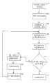
The flow chart of Fig. 7 shows a kind of exemplary automatic to-fill procedure.Certainly, the user can manually carry out to-fill procedure, and this does not depart from scope of the present invention yet.In first step of automatic to-fill procedure,step 902, the packing volume that input is wanted.In case input should be worth, the user can trigger the startup of automatic to-fill procedure in step 904.As response, injector system will slowly be pulled out the contrast agent that makes small size instep 906 and got into syringe, and the while syringe is points upwards basically.Direction is determined so that syringe is positioned on the end opposite of head and be considered to points upwards basically with tilt 45 degree or injector still less of vertical line; Yet, be preferred less than the inclination angle of 20 degree.Being pumped in the syringe with enough slow speed with the small size that does not make the contrast fluid that fluid inflates is that the operator who is enough to be performed to-fill procedure visually notices, and is at least the volume of 20ml usually.
In case the contrast agent of small size is in the syringe, instep 908, injector system is the direction of (or the operator manually) counter-rotating injector piston automatically, and contrast fluid is discharged from syringe like this.Particularly, so operated piston makes at least a portion fluid in the syringe flow through the filling pipe and get into contrast container once more.Therefore, all air have been discharged from filling pipe and syringe.
Do not have air at the syringe that does not have air with filling Guan Zhongyi, instep 910, under situation about having reduced owing to the risk of inflating the bubble that causes, injector system can be switched on to draw back programme controlled volume.Now the speed that can be drawn back of contrast agent is greater than the speed that does not resemblestep 908 place in advance when filling pipe and syringe air-out.
During to-fill procedure, when remaining contrast agent in the container is not enough to provide the required contrast volume of correct filling syringe, can use similar technology to change the contrast agent bottle.This technology is shown in the step 912-920 of the flow chart of Fig. 7.Itself is useful as the method for in the to-fill procedure process, changing contrast container for this technology, and perhaps this technology can be the part of automatic to-fill procedure shown in Figure 7.
In filling process, contrast container possibly be cleared instep 912, and when obtaining final amount from container, air is incorporated in the filling pipe.When container was empty, the operator can utilize the operator interface of injector system and suspend to-fill procedure in step 916.Suspend the result of to-fill procedure as the operator, piston stops to make can be instep 918 with the new empty container of container replacement with contrast agent.
Then, instep 920, the operator can be restarted to-fill procedure.Through restarting, piston is operated the air of filling in pipe and the syringe to release in opposite direction automatically.Instep 908, discharging all air from system is till the contrast fluid of operated piston up to syringe gets into new container once more in the direction, to guarantee.In case all air are discharged from, instep 910, thereby the piston direction of can reversing is filled syringe with the suction contrast agent.The speed when if the speed that present contrast agent is drawn back is not discharged from faster than air.There is new contrast container to use, can accomplishes the filling of syringe instep 914.
Though the explanation of the flow chart of Fig. 7 is included in many steps the interaction with the operator, these processes can be carried out said step and automatization with the intervention that need not the operator through the suitable programmed of injector system.For the injector system of programming in this way, need make hypothesis about the volume capacity of filling pipe used between syringe and the contrast container.Know this volume capacity will allow the enough contrast agent of auto-programming suction make a small amount of arrive syringe and with time of being enough to discharge contrast agent and speed counter-rotating piston to guarantee successfully to discharge all air with filling to manage the two from syringe.
In addition; But the program of the Fig. 7 of automatization; Like this when the operator replaces contrast container and continuation of indication injector system or recovery to-fill procedure; Thereby injector may command piston direction and speed are guaranteed to remove the air of filling in the pipe with the enough contrast agent of automatic discharge, thereby auto-reverse then piston aspirates more contrast agent with faster rate.
Though though the illustrated example through various embodiment the present invention and these embodiment very at length are described, the applicant does not want by any way the scope of claim is restricted to these details.Additional advantage is conspicuous with remodeling for those of ordinary skill in the art.Therefore, its aspect illustrative examples of being not limited to specific details, representational system, equipment and method and illustrating with describe widely of the present invention.Therefore, under the situation of the spirit of the general inventive concept that does not break away from the applicant and scope, can depart from these details.
Claims (11)
1. one kind is passed through the automatic syringe fill method that the contrast-medium injection machine is carried out, and comprising:
This injector is pumped in the syringe of injector with the fluid of first rate with first amount;
Injector with first the amount fluid be pumped in the syringe after, this injector automatically makes the piston direction of injector reverse, so that at least a portion fluid is discharged from syringe; With
Injector automatically with piston direction reverse after, injector automatically with the second speed withdrawal piston faster than first rate, is pumped in the syringe with the fluid with second amount.
2. automatic syringe fill method as claimed in claim 1, wherein, first rate is enough slow, so that fluid can not inflated.
3. according to claim 1 or claim 2 automatic syringe fill method, wherein, first amount is the amount seen by the operator of injector of being enough to.
4. according to claim 1 or claim 2 automatic syringe fill method, wherein, first amount is at least about 20ml.
5. according to claim 1 or claim 2 automatic syringe fill method; Wherein, injector automatically withdraw piston when accomplishing in the syringe fluidic amount be the required Fluid Volume that enters into injector of operator of injector before injector is pumped into the fluid of first amount in the syringe.
6. according to claim 1 or claim 2 automatic syringe fill method, wherein, injector be designed so that in following process syringe basically towards on:
Injector is pumped into the process in the syringe with the fluid of first amount;
The process that injector is automatically reverse with the direction of piston; With
Automatically the withdraw process of piston of injector.
7. method that is used for changing contrast container at the syringe filling process, this method comprises:
Filling pipe through being connected between the syringe and first contrast container is filled syringe with in first fill rate and second fill rate at least one;
When first contrast container basic overhead the time suspend and fill;
The filling pipe of connection between the syringe and second contrast container;
Basically discharge all air from the filling pipe that is connected between the syringe and second contrast container, wherein second contrast container is discharged and discharge process, got into at least some contrast agent through filling pipe from syringe; And
After this, with than first fill rate faster second fill rate continue to fill syringe from second contrast container.
8. method as claimed in claim 7, wherein, discharge comprises:
To discharge syringe and get into second contrast container from a part of contrast agent that first contrast container obtains through filling pipe.
9. like claim 7 or 8 described methods, wherein, discharge comprises from syringe discharges all air basically.
10. like claim 7 or 8 described methods, wherein, the direction of syringe make the discharge end of syringe in the process of filling, discharging and continuing, be positioned at syringe tube above.
11. like claim 7 or 8 described methods, wherein, the two discharge end through syringe in discharge process of air and contrast agent is discharged.
Applications Claiming Priority (2)
| Application Number | Priority Date | Filing Date | Title |
|---|---|---|---|
| US10/750,427US7621892B2 (en) | 2003-12-31 | 2003-12-31 | Contrast container holder and method to fill syringes |
| US10/750,427 | 2003-12-31 |
Related Parent Applications (1)
| Application Number | Title | Priority Date | Filing Date |
|---|---|---|---|
| CNB2004800396111ADivisionCN100548397C (en) | 2003-12-31 | 2004-12-09 | Contrast container holder and method for filling a syringe |
Publications (2)
| Publication Number | Publication Date |
|---|---|
| CN101485910A CN101485910A (en) | 2009-07-22 |
| CN101485910Btrue CN101485910B (en) | 2012-04-18 |
Family
ID=34711276
Family Applications (2)
| Application Number | Title | Priority Date | Filing Date |
|---|---|---|---|
| CNB2004800396111AExpired - Fee RelatedCN100548397C (en) | 2003-12-31 | 2004-12-09 | Contrast container holder and method for filling a syringe |
| CN2009100050620AExpired - Fee RelatedCN101485910B (en) | 2003-12-31 | 2004-12-09 | Contrast container holder and method to fill syringes |
Family Applications Before (1)
| Application Number | Title | Priority Date | Filing Date |
|---|---|---|---|
| CNB2004800396111AExpired - Fee RelatedCN100548397C (en) | 2003-12-31 | 2004-12-09 | Contrast container holder and method for filling a syringe |
Country Status (7)
| Country | Link |
|---|---|
| US (2) | US7621892B2 (en) |
| EP (2) | EP2113269B1 (en) |
| JP (4) | JP4976137B2 (en) |
| CN (2) | CN100548397C (en) |
| CA (1) | CA2552067C (en) |
| ES (2) | ES2559424T3 (en) |
| WO (1) | WO2005065747A2 (en) |
Families Citing this family (28)
| Publication number | Priority date | Publication date | Assignee | Title |
|---|---|---|---|---|
| USD550838S1 (en)* | 2004-10-13 | 2007-09-11 | Liebel-Flarsheim Company | Power injection system face plate |
| US20060079842A1 (en)* | 2004-10-13 | 2006-04-13 | Liebel-Flarsheim Company | Powerhead control in a power injection system |
| US7507221B2 (en) | 2004-10-13 | 2009-03-24 | Mallinckrodt Inc. | Powerhead of a power injection system |
| US20090221914A1 (en)* | 2005-09-14 | 2009-09-03 | Acist Medical Systems, Inc. | Medical Fluid Injection System |
| DE102006017360A1 (en)* | 2006-04-11 | 2007-10-18 | Diasys Diagnostic Systems Gmbh | Method for dosing and mixing |
| EP2158928A2 (en)* | 2007-04-11 | 2010-03-03 | Mallinckrodt Inc. | Universal syringe |
| WO2008137375A2 (en)* | 2007-05-04 | 2008-11-13 | Mallinckrodt Inc. | Methods for controlling medical fluid injections |
| ES2391719T3 (en)* | 2007-11-19 | 2012-11-29 | Mallinckrodt Llc | Fluid delivery system with multi-dose fluid source |
| JP2012507357A (en)* | 2008-10-31 | 2012-03-29 | マリンクロッド エルエルシー | Multiple dose injection system |
| EP2456572B1 (en) | 2009-07-24 | 2014-02-26 | BAYER Medical Care Inc. | Multi-fluid medical injector system |
| US8604265B2 (en) | 2010-04-16 | 2013-12-10 | Kci Licensing, Inc. | Dressings and methods for treating a tissue site on a patient |
| US8403902B2 (en)* | 2010-05-18 | 2013-03-26 | Kci Licensing, Inc. | Reduced-pressure medical systems and methods employing a moisture processing device |
| GB2506918A (en)* | 2012-10-12 | 2014-04-16 | Cambridge Consultants | Injector device |
| US20150133861A1 (en) | 2013-11-11 | 2015-05-14 | Kevin P. McLennan | Thermal management system and method for medical devices |
| DE202014001525U1 (en) | 2014-02-19 | 2014-03-27 | H & B Electronic Gmbh & Co. Kg | Continuous infusion device |
| US10143795B2 (en) | 2014-08-18 | 2018-12-04 | Icu Medical, Inc. | Intravenous pole integrated power, control, and communication system and method for an infusion pump |
| NZ737340A (en) | 2015-05-26 | 2019-06-28 | Icu Medical Inc | Disposable infusion fluid delivery device for programmable large volume drug delivery |
| DK3341048T3 (en)* | 2015-08-28 | 2023-08-21 | Bayer Healthcare Llc | SYSTEM AND METHOD FOR VERIFYING INJECTION FLUID FILLING AND IMAGE RECOGNITION OF POWER INJECTOR SYSTEM TRAITS |
| EP3481462B1 (en) | 2016-07-06 | 2021-03-24 | Bayer Healthcare LLC | Contrast heating system with in-line contrast warmer |
| USD806233S1 (en) | 2016-09-09 | 2017-12-26 | Liebel-Flarsheim Company Llc | Powerhead for a power injection system |
| CN109420214A (en)* | 2017-08-24 | 2019-03-05 | 南京感控通化工产品经营部 | A kind of automatic pipetting systems of syringe |
| DE102018104002B3 (en)* | 2018-02-22 | 2018-11-08 | Ulrich Gmbh & Co. Kg | Container holder with tempering device for an injector |
| USD939079S1 (en) | 2019-08-22 | 2021-12-21 | Icu Medical, Inc. | Infusion pump |
| FR3114969B1 (en)* | 2020-10-09 | 2024-06-14 | Assist Publique Hopitaux De Paris Ap Hp | Drug Dosing Instrument Holder |
| GB2600135B (en)* | 2020-10-22 | 2022-11-30 | Keymed Medical & Industrial Equipment Ltd | Adjustable bottle support |
| CN113230502A (en)* | 2021-06-28 | 2021-08-10 | 聊城市人民医院 | Paediatrics infusion fixing device |
| USD1052728S1 (en) | 2021-11-12 | 2024-11-26 | Icu Medical, Inc. | Medical fluid infusion pump |
| JPWO2023181578A1 (en)* | 2022-03-24 | 2023-09-28 |
Citations (5)
| Publication number | Priority date | Publication date | Assignee | Title |
|---|---|---|---|---|
| US4065230A (en)* | 1975-01-17 | 1977-12-27 | Hart Associates, Inc. | Reciprocating infusion pump and directional adapter set for use therewith |
| US5925022A (en)* | 1996-11-22 | 1999-07-20 | Liebel-Flarsheim Company | Medical fluid injector |
| US6221045B1 (en)* | 1995-04-20 | 2001-04-24 | Acist Medical Systems, Inc. | Angiographic injector system with automatic high/low pressure switching |
| EP1323446A2 (en)* | 2001-12-28 | 2003-07-02 | Nipro Corporation | Syringe-type container for liquid medicine |
| CN1440301A (en)* | 2000-07-10 | 2003-09-03 | 梅德拉股份有限公司 | Improved Medical Syringe System |
Family Cites Families (38)
| Publication number | Priority date | Publication date | Assignee | Title |
|---|---|---|---|---|
| US3602272A (en)* | 1969-05-07 | 1971-08-31 | Becton Dickinson Co | Manual syringe filling device |
| US3935883A (en)* | 1974-08-19 | 1976-02-03 | Stach Paul E | Syringe filling apparatus with disposable fluid conducting elements |
| US4562829A (en) | 1983-02-28 | 1986-01-07 | E. R. Squibb & Sons, Inc. | Strontium-rubidium infusion system |
| JPH0337634Y2 (en)* | 1985-10-08 | 1991-08-08 | ||
| EP0434672B1 (en) | 1987-06-19 | 1994-12-14 | The University Of Melbourne | Infusion pump |
| US4883101A (en)* | 1988-06-27 | 1989-11-28 | Jordan Enterprises | Filling device with sound indicator for filling injection syringe |
| US5012845A (en)* | 1988-08-18 | 1991-05-07 | Dynatech Precision Sampling Corporation | Fluid injector |
| US5298023A (en) | 1991-03-08 | 1994-03-29 | Habley Medical Technology Corporation | Multiple pharmaceutical dispenser with accumulator |
| US5300031A (en) | 1991-06-07 | 1994-04-05 | Liebel-Flarsheim Company | Apparatus for injecting fluid into animals and disposable front loadable syringe therefor |
| US5425716A (en) | 1991-08-09 | 1995-06-20 | Atom Kabushiki Kaisha | Infusion apparatus |
| CA2121685A1 (en)* | 1992-08-19 | 1994-03-03 | Robert Hardie | Apparatus for dispensing substances which are biologically hazardous |
| US5334162A (en) | 1993-03-15 | 1994-08-02 | Eli Lilly And Company | Cartridge assembly for a lyophilized compound forming a disposable portion of an injector pen and method for same |
| CA2129284C (en) | 1993-11-24 | 1999-03-09 | Kenneth J. Niehoff | Controlling plunger drives for fluid injection in animals |
| US5431201A (en)* | 1993-12-03 | 1995-07-11 | Technology 2000 Incororated | Robotic admixture system |
| US5385559A (en)* | 1993-12-20 | 1995-01-31 | R. Jason Newsom | Syringe filling and metering device |
| US5533978A (en)* | 1994-11-07 | 1996-07-09 | Teirstein; Paul S. | Method and apparatus for uninterrupted delivery of radiographic dye |
| US5487738A (en)* | 1995-03-31 | 1996-01-30 | Sciulli; Eugene B. | Apparatus for drawing fluids into a hypodermic syringe |
| US5647409A (en)* | 1995-04-04 | 1997-07-15 | Allergan | On-site syringe filling apparatus for viscoelastic materials, and corresponding method for on-site syringe filling |
| US6099502A (en)* | 1995-04-20 | 2000-08-08 | Acist Medical Systems, Inc. | Dual port syringe |
| US5573515A (en)* | 1995-04-20 | 1996-11-12 | Invasatec, Inc. | Self purging angiographic injector |
| PT821566E (en) | 1995-04-20 | 2004-03-31 | Acist Medical Sys Inc | ANGIOGRAPHIC INJECTOR |
| US6656157B1 (en)* | 1995-04-20 | 2003-12-02 | Acist Medical Systems, Inc. | Infinitely refillable syringe |
| US6302160B2 (en) | 1998-11-14 | 2001-10-16 | Pen Jet Corporation | Apparatus and method for filling an ampule of a needle-less injector |
| MXPA02005099A (en)* | 1999-11-24 | 2002-11-07 | Medrad Inc | Front-loading medical injector and syringe. |
| AU1816701A (en) | 1999-12-07 | 2001-06-18 | Medrad, Inc. | Syringes, syringe tubing and fluid transfer systems |
| US6652489B2 (en) | 2000-02-07 | 2003-11-25 | Medrad, Inc. | Front-loading medical injector and syringes, syringe interfaces, syringe adapters and syringe plungers for use therewith |
| US6471674B1 (en) | 2000-04-21 | 2002-10-29 | Medrad, Inc. | Fluid delivery systems, injector systems and methods of fluid delivery |
| ATE551085T1 (en) | 2000-07-20 | 2012-04-15 | Acist Medical Sys Inc | SYRINGE Plunger LOCKING MECHANISM |
| US7566320B2 (en)* | 2001-02-14 | 2009-07-28 | Acist Medical Systems, Inc. | Fluid injector system |
| EP1427463A2 (en) | 2001-04-27 | 2004-06-16 | PenJet Corporation | Method and apparatus for filling or refilling a needle-less injector |
| JP3809114B2 (en) | 2001-11-05 | 2006-08-16 | スーガン株式会社 | Channel switching device and contrast medium injection tube used in the device |
| US6780170B2 (en)* | 2002-05-15 | 2004-08-24 | Liebel-Flarsheim Company | Hydraulic remote for a medical fluid injector |
| US7553294B2 (en)* | 2002-05-30 | 2009-06-30 | Medrad, Inc. | Syringe plunger sensing mechanism for a medical injector |
| US6929619B2 (en)* | 2002-08-02 | 2005-08-16 | Liebel-Flarshiem Company | Injector |
| US7703483B2 (en)* | 2004-06-04 | 2010-04-27 | Acist Medical Systems, Inc. | Peristaltic syringe filling station |
| US7163031B2 (en)* | 2004-06-15 | 2007-01-16 | Mallinckrodt Inc. | Automated dispensing system and associated method of use |
| US7398802B2 (en)* | 2004-09-02 | 2008-07-15 | Baker James W | System for dispensing biological fluids |
| WO2007133942A2 (en) | 2006-05-11 | 2007-11-22 | Acist Medical System, Inc. | Air purge in a fluid injection system |
- 2003
- 2003-12-31USUS10/750,427patent/US7621892B2/ennot_activeExpired - Fee Related
- 2004
- 2004-12-09CNCNB2004800396111Apatent/CN100548397C/ennot_activeExpired - Fee Related
- 2004-12-09ESES09075325.2Tpatent/ES2559424T3/ennot_activeExpired - Lifetime
- 2004-12-09ESES04813537.0Tpatent/ES2559408T3/ennot_activeExpired - Lifetime
- 2004-12-09EPEP09075325.2Apatent/EP2113269B1/ennot_activeExpired - Lifetime
- 2004-12-09EPEP04813537.0Apatent/EP1699507B1/ennot_activeExpired - Lifetime
- 2004-12-09WOPCT/US2004/041225patent/WO2005065747A2/enactiveApplication Filing
- 2004-12-09CACA2552067Apatent/CA2552067C/ennot_activeExpired - Fee Related
- 2004-12-09JPJP2006547073Apatent/JP4976137B2/ennot_activeExpired - Lifetime
- 2004-12-09CNCN2009100050620Apatent/CN101485910B/ennot_activeExpired - Fee Related
- 2009
- 2009-11-12USUS12/617,558patent/US8141598B2/ennot_activeExpired - Fee Related
- 2010
- 2010-12-08JPJP2010274142Apatent/JP5253486B2/ennot_activeExpired - Fee Related
- 2012
- 2012-10-17JPJP2012229976Apatent/JP5702350B2/ennot_activeExpired - Fee Related
- 2013
- 2013-12-24JPJP2013265820Apatent/JP2014079642A/ennot_activeWithdrawn
Patent Citations (5)
| Publication number | Priority date | Publication date | Assignee | Title |
|---|---|---|---|---|
| US4065230A (en)* | 1975-01-17 | 1977-12-27 | Hart Associates, Inc. | Reciprocating infusion pump and directional adapter set for use therewith |
| US6221045B1 (en)* | 1995-04-20 | 2001-04-24 | Acist Medical Systems, Inc. | Angiographic injector system with automatic high/low pressure switching |
| US5925022A (en)* | 1996-11-22 | 1999-07-20 | Liebel-Flarsheim Company | Medical fluid injector |
| CN1440301A (en)* | 2000-07-10 | 2003-09-03 | 梅德拉股份有限公司 | Improved Medical Syringe System |
| EP1323446A2 (en)* | 2001-12-28 | 2003-07-02 | Nipro Corporation | Syringe-type container for liquid medicine |
Also Published As
| Publication number | Publication date |
|---|---|
| JP4976137B2 (en) | 2012-07-18 |
| EP1699507A2 (en) | 2006-09-13 |
| JP5253486B2 (en) | 2013-07-31 |
| JP2007516779A (en) | 2007-06-28 |
| US20100051135A1 (en) | 2010-03-04 |
| JP2011045784A (en) | 2011-03-10 |
| CN100548397C (en) | 2009-10-14 |
| CA2552067C (en) | 2013-09-10 |
| EP1699507B1 (en) | 2015-11-11 |
| ES2559424T3 (en) | 2016-02-12 |
| JP2014079642A (en) | 2014-05-08 |
| CA2552067A1 (en) | 2005-07-21 |
| JP2013010037A (en) | 2013-01-17 |
| CN1901952A (en) | 2007-01-24 |
| CN101485910A (en) | 2009-07-22 |
| US20050148868A1 (en) | 2005-07-07 |
| US8141598B2 (en) | 2012-03-27 |
| EP2113269A1 (en) | 2009-11-04 |
| US7621892B2 (en) | 2009-11-24 |
| WO2005065747A3 (en) | 2005-11-10 |
| JP5702350B2 (en) | 2015-04-15 |
| WO2005065747A2 (en) | 2005-07-21 |
| EP2113269B1 (en) | 2015-11-04 |
| ES2559408T3 (en) | 2016-02-12 |
Similar Documents
| Publication | Publication Date | Title |
|---|---|---|
| CN101485910B (en) | Contrast container holder and method to fill syringes | |
| JP2007516779A5 (en) | ||
| CN101518662B (en) | Injector auto purge | |
| JP5280556B2 (en) | Injector automatic purge | |
| EP2283883B1 (en) | Fluid delivery system with multi-dose fluid source | |
| US20010018937A1 (en) | Method and device for pre-filling a syringe with a contrast agent | |
| EP1016427A2 (en) | A method and device for filing a syringe with a chemical solution | |
| CN101960458A (en) | Power injector with help function | |
| CN1901950A (en) | Injector with changeable syringe constants | |
| WO2010019456A1 (en) | Injector auto purge | |
| EP1829576A1 (en) | Chemical liquid injection device |
Legal Events
| Date | Code | Title | Description |
|---|---|---|---|
| C06 | Publication | ||
| PB01 | Publication | ||
| C10 | Entry into substantive examination | ||
| SE01 | Entry into force of request for substantive examination | ||
| C53 | Correction of patent for invention or patent application | ||
| CB02 | Change of applicant information | Address after:American Missouri Applicant after:Mallinckrodt Inc. Address before:American Missouri Applicant before:Mallinckrodt Inc. | |
| C14 | Grant of patent or utility model | ||
| GR01 | Patent grant | ||
| ASS | Succession or assignment of patent right | Owner name:LIEBEL-FLARSHEIM CO., LTD. Free format text:FORMER OWNER: MALLINCKRODT INC. Effective date:20150427 | |
| C41 | Transfer of patent application or patent right or utility model | ||
| TR01 | Transfer of patent right | Effective date of registration:20150427 Address after:American Missouri Patentee after:Liebel Flarsheim Co. Address before:American Missouri Patentee before:Mallinckrodt Inc. | |
| CF01 | Termination of patent right due to non-payment of annual fee | Granted publication date:20120418 Termination date:20191209 | |
| CF01 | Termination of patent right due to non-payment of annual fee |