CN101480104A - Method and device for driving an array of light sources - Google Patents
Method and device for driving an array of light sourcesDownload PDFInfo
- Publication number
- CN101480104A CN101480104ACNA2007800236065ACN200780023606ACN101480104ACN 101480104 ACN101480104 ACN 101480104ACN A2007800236065 ACNA2007800236065 ACN A2007800236065ACN 200780023606 ACN200780023606 ACN 200780023606ACN 101480104 ACN101480104 ACN 101480104A
- Authority
- CN
- China
- Prior art keywords
- signal
- light source
- bus
- switching frequency
- duty cycle
- Prior art date
- Legal status (The legal status is an assumption and is not a legal conclusion. Google has not performed a legal analysis and makes no representation as to the accuracy of the status listed.)
- Granted
Links
Images


Classifications
- H—ELECTRICITY
- H05—ELECTRIC TECHNIQUES NOT OTHERWISE PROVIDED FOR
- H05B—ELECTRIC HEATING; ELECTRIC LIGHT SOURCES NOT OTHERWISE PROVIDED FOR; CIRCUIT ARRANGEMENTS FOR ELECTRIC LIGHT SOURCES, IN GENERAL
- H05B45/00—Circuit arrangements for operating light-emitting diodes [LED]
- H05B45/10—Controlling the intensity of the light
- H—ELECTRICITY
- H05—ELECTRIC TECHNIQUES NOT OTHERWISE PROVIDED FOR
- H05B—ELECTRIC HEATING; ELECTRIC LIGHT SOURCES NOT OTHERWISE PROVIDED FOR; CIRCUIT ARRANGEMENTS FOR ELECTRIC LIGHT SOURCES, IN GENERAL
- H05B45/00—Circuit arrangements for operating light-emitting diodes [LED]
- H05B45/20—Controlling the colour of the light
- H—ELECTRICITY
- H05—ELECTRIC TECHNIQUES NOT OTHERWISE PROVIDED FOR
- H05B—ELECTRIC HEATING; ELECTRIC LIGHT SOURCES NOT OTHERWISE PROVIDED FOR; CIRCUIT ARRANGEMENTS FOR ELECTRIC LIGHT SOURCES, IN GENERAL
- H05B45/00—Circuit arrangements for operating light-emitting diodes [LED]
- H05B45/30—Driver circuits
- H05B45/305—Frequency-control circuits
- H—ELECTRICITY
- H05—ELECTRIC TECHNIQUES NOT OTHERWISE PROVIDED FOR
- H05B—ELECTRIC HEATING; ELECTRIC LIGHT SOURCES NOT OTHERWISE PROVIDED FOR; CIRCUIT ARRANGEMENTS FOR ELECTRIC LIGHT SOURCES, IN GENERAL
- H05B45/00—Circuit arrangements for operating light-emitting diodes [LED]
- H05B45/30—Driver circuits
- H05B45/37—Converter circuits
- H—ELECTRICITY
- H05—ELECTRIC TECHNIQUES NOT OTHERWISE PROVIDED FOR
- H05B—ELECTRIC HEATING; ELECTRIC LIGHT SOURCES NOT OTHERWISE PROVIDED FOR; CIRCUIT ARRANGEMENTS FOR ELECTRIC LIGHT SOURCES, IN GENERAL
- H05B47/00—Circuit arrangements for operating light sources in general, i.e. where the type of light source is not relevant
- H05B47/10—Controlling the light source
- H05B47/155—Coordinated control of two or more light sources
- H—ELECTRICITY
- H05—ELECTRIC TECHNIQUES NOT OTHERWISE PROVIDED FOR
- H05B—ELECTRIC HEATING; ELECTRIC LIGHT SOURCES NOT OTHERWISE PROVIDED FOR; CIRCUIT ARRANGEMENTS FOR ELECTRIC LIGHT SOURCES, IN GENERAL
- H05B47/00—Circuit arrangements for operating light sources in general, i.e. where the type of light source is not relevant
- H05B47/10—Controlling the light source
- H05B47/175—Controlling the light source by remote control
- H05B47/185—Controlling the light source by remote control via power line carrier transmission
- H—ELECTRICITY
- H05—ELECTRIC TECHNIQUES NOT OTHERWISE PROVIDED FOR
- H05B—ELECTRIC HEATING; ELECTRIC LIGHT SOURCES NOT OTHERWISE PROVIDED FOR; CIRCUIT ARRANGEMENTS FOR ELECTRIC LIGHT SOURCES, IN GENERAL
- H05B45/00—Circuit arrangements for operating light-emitting diodes [LED]
- H05B45/30—Driver circuits
- H05B45/37—Converter circuits
- H05B45/3725—Switched mode power supply [SMPS]
- Y—GENERAL TAGGING OF NEW TECHNOLOGICAL DEVELOPMENTS; GENERAL TAGGING OF CROSS-SECTIONAL TECHNOLOGIES SPANNING OVER SEVERAL SECTIONS OF THE IPC; TECHNICAL SUBJECTS COVERED BY FORMER USPC CROSS-REFERENCE ART COLLECTIONS [XRACs] AND DIGESTS
- Y02—TECHNOLOGIES OR APPLICATIONS FOR MITIGATION OR ADAPTATION AGAINST CLIMATE CHANGE
- Y02B—CLIMATE CHANGE MITIGATION TECHNOLOGIES RELATED TO BUILDINGS, e.g. HOUSING, HOUSE APPLIANCES OR RELATED END-USER APPLICATIONS
- Y02B20/00—Energy efficient lighting technologies, e.g. halogen lamps or gas discharge lamps
- Y02B20/30—Semiconductor lamps, e.g. solid state lamps [SSL] light emitting diodes [LED] or organic LED [OLED]
- Y—GENERAL TAGGING OF NEW TECHNOLOGICAL DEVELOPMENTS; GENERAL TAGGING OF CROSS-SECTIONAL TECHNOLOGIES SPANNING OVER SEVERAL SECTIONS OF THE IPC; TECHNICAL SUBJECTS COVERED BY FORMER USPC CROSS-REFERENCE ART COLLECTIONS [XRACs] AND DIGESTS
- Y02—TECHNOLOGIES OR APPLICATIONS FOR MITIGATION OR ADAPTATION AGAINST CLIMATE CHANGE
- Y02B—CLIMATE CHANGE MITIGATION TECHNOLOGIES RELATED TO BUILDINGS, e.g. HOUSING, HOUSE APPLIANCES OR RELATED END-USER APPLICATIONS
- Y02B90/00—Enabling technologies or technologies with a potential or indirect contribution to GHG emissions mitigation
- Y02B90/20—Smart grids as enabling technology in buildings sector
- Y—GENERAL TAGGING OF NEW TECHNOLOGICAL DEVELOPMENTS; GENERAL TAGGING OF CROSS-SECTIONAL TECHNOLOGIES SPANNING OVER SEVERAL SECTIONS OF THE IPC; TECHNICAL SUBJECTS COVERED BY FORMER USPC CROSS-REFERENCE ART COLLECTIONS [XRACs] AND DIGESTS
- Y04—INFORMATION OR COMMUNICATION TECHNOLOGIES HAVING AN IMPACT ON OTHER TECHNOLOGY AREAS
- Y04S—SYSTEMS INTEGRATING TECHNOLOGIES RELATED TO POWER NETWORK OPERATION, COMMUNICATION OR INFORMATION TECHNOLOGIES FOR IMPROVING THE ELECTRICAL POWER GENERATION, TRANSMISSION, DISTRIBUTION, MANAGEMENT OR USAGE, i.e. SMART GRIDS
- Y04S20/00—Management or operation of end-user stationary applications or the last stages of power distribution; Controlling, monitoring or operating thereof
Landscapes
- Circuit Arrangement For Electric Light Sources In General (AREA)
- Discharge-Lamp Control Circuits And Pulse- Feed Circuits (AREA)
- Led Devices (AREA)
Abstract
Translated fromChinese
Description
Translated fromChinese技术领域technical field
本发明一般涉及彩色照明领域。更特别的是,本发明涉及一种包括多个光源的照明设备,其颜色和亮度级是可控制的。在以下的说明中,假设将每个光源实现为LED,但是也能够利用其它类型的光源实现本发明,例如TL灯、卤素灯等。The present invention generally relates to the field of colored lighting. More particularly, the present invention relates to a lighting device comprising a plurality of light sources, the color and brightness level of which are controllable. In the following description, it is assumed that each light source is implemented as an LED, but it is also possible to implement the invention with other types of light sources, such as TL lamps, halogen lamps, and the like.
背景技术Background technique
一般而言,希望照明设备能够生成具有可变光强度(变暗)和可变颜色的光。本领域技术人员应当清楚并且因此不需要详细阐述,可以利用包括生成相互不同颜色的光的三基色LED的配置,生成大部分色域中所有可能颜色的光。在典型实例中,一个LED生成红光,第二个LED生成绿光,并且第三个LED生成蓝光。这三个基色LED的组合光输出具有位于由这三个基色LED的颜色限定的颜色三角内的混合颜色,并且该颜色三角内的精确色点取决于三基色LED的相互的强度比。因此,通过改变三个基色LED之一的相对强度能够实现该设置的色点的改变,而通过改变全部基色LED的强度到相同的程度,能够实现光输出强度的改变,同时保持色点。In general, it is desirable for a lighting device to be able to generate light with variable light intensity (dimming) and variable color. It should be clear to those skilled in the art, and thus does not require elaboration, that all possible colors of light in most color gamuts can be generated with a configuration comprising three primary color LEDs generating mutually different colors of light. In a typical example, one LED generates red light, a second LED generates green light, and a third LED generates blue light. The combined light output of the three primary LEDs has a mixed color within a color triangle defined by the colors of the three primary LEDs, and the exact color point within the color triangle depends on the mutual intensity ratios of the three primary LEDs. Thus, a change in the color point of the setup can be achieved by varying the relative intensity of one of the three primary LEDs, while a change in light output intensity can be achieved by varying the intensity of all primary LEDs to the same extent while maintaining the color point.
已经注意到,可以使用具有相互不同颜色的多于三个基色LED;在这种情况下,通过适当的改变,也能够应用本发明,这对于本领域技术人员而言是显而易见的。It has been noted that it is possible to use more than three primary LEDs with mutually different colors; in this case, with appropriate modifications, the invention can also be applied, as will be obvious to a person skilled in the art.
以下,包括三个(或更多个)不同基色光源的基本组件由“点(spot)”表示。因此,以其最小的实施方案,点正好包括三个LED。然而,可能的是利用基本上相互相同的LED组成的阵列来实现基色光源,每个LED生成基本上相同的颜色,将它们并联和/或串联连接以提高光输出。以下,假设由一个LED实现每个基色光源。In the following, a basic component comprising three (or more) light sources of different primary colors is denoted by a "spot". Thus, in its smallest embodiment, the dot includes exactly three LEDs. However, it is possible to implement the primary color light source with an array of substantially mutually identical LEDs, each generating substantially the same color, connecting them in parallel and/or in series to increase the light output. Hereinafter, it is assumed that each primary color light source is realized by one LED.
为了控制各个基色光源的强度,向点提供微控制器。该微控制器具有例如从中央微控制器或者PC接收设定信号的输入端。该微控制器还具有三个控制输出端,一个输出端针对一个LED,以控制各个LED的工作。通常,以可变占空比来操纵该LED,以实现各个光强度的变化。To control the intensity of the individual primary light sources, a microcontroller is provided to the dots. The microcontroller has inputs for receiving setting signals, eg from a central microcontroller or a PC. The microcontroller also has three control outputs, one for each LED, to control the operation of each LED. Typically, the LEDs are manipulated with variable duty cycles to achieve individual light intensity variations.
一种照明系统可以包括应以相同方式工作的两个或多个点,即生成相同的光颜色和强度级。因此,随着点数量的增加,微控制器的数量也增加。这样就造成了成本方面的问题,这是因为微控制器是点中主要的成本因素。A lighting system can consist of two or more points that should work in the same way, i.e. generate the same light color and intensity level. Therefore, as the number of points increases, the number of microcontrollers also increases. This creates a cost problem, because the microcontroller is the main cost factor in the point.
本发明旨在解决这个问题。更具体地讲,本发明旨在提供一种相对简单和低成本的照明系统,其包括两个或多个点,其能够仅以一个单独的公共控制器进行工作。The present invention aims to solve this problem. More specifically, the invention aims to provide a relatively simple and low-cost lighting system comprising two or more points capable of operating with only a single common controller.
发明内容Contents of the invention
为此,本发明提供了一种通信系统,其仅需要传送LED的电力和LED的命令信号的两条线。To this end, the present invention provides a communication system that requires only two wires to transmit the power of the LED and the command signal of the LED.
已经注意到,EP1555859公开了一种用于照明系统的通信系统,其中通过公共的两线总线控制多个LED,该总线传送LED的电力以及LED的命令信号。在该现有技术的系统中,该命令信号是编码消息。每个消息包含表示该消息所针对的LED的编码地址以及表示该LED所需要执行的动作的编码指令。尽管这种系统确实实现了中央控制,但是实际上由于每个点需要具有用于接收、解码和处理该编码指令的智能设备(例如微处理器)而使其相当复杂和成本高。It has been noted that EP1555859 discloses a communication system for a lighting system in which a plurality of LEDs are controlled through a common two-wire bus which carries power for the LEDs as well as command signals for the LEDs. In this prior art system, the command signal is an encoded message. Each message contains an encoded address indicating the LED that the message is for and an encoded instruction indicating the action that the LED needs to perform. While such a system does achieve central control, it is actually rather complex and costly since each point needs to have an intelligent device (such as a microprocessor) for receiving, decoding and processing the encoded instructions.
在本发明提出的系统中,该命令信号简单的多,并且直接控制各个LED。将命令信号实现为小频带内的信号,该信号存在或者不存在。对于不同的LED而言,使用不同的频带。每个点包括对应于各个频带的滤波器。利用该滤波器的输出信号直接控制LED:存在或者不存在该信号表示LED的接通或断开,因此利用中央控制器通过对命令信号的占空比控制,直接控制LED的占空比控制。In the system proposed by the present invention, the command signal is much simpler and directly controls the individual LEDs. The command signal is implemented as a signal in a small frequency band, which may or may not be present. For different LEDs, different frequency bands are used. Each point includes filters corresponding to respective frequency bands. The output signal of the filter is used to directly control the LED: the presence or absence of the signal indicates that the LED is on or off, so the central controller is used to directly control the duty cycle control of the LED through the duty cycle control of the command signal.
附图说明Description of drawings
通过以下参照附图的说明进一步阐述本发明的这些及其它方面、特征和优点,其中相同的附图标记表示相同或类似的部件,并且在附图中:These and other aspects, features and advantages of the present invention are further elucidated by the following description with reference to the accompanying drawings, in which like reference numerals indicate the same or similar parts, and in which:
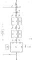
图1是示意表示照明系统的结构图;Figure 1 is a schematic diagram showing the structure of the lighting system;
图2是更详细地表示控制器的实施例的结构图;Figure 2 is a block diagram representing an embodiment of the controller in more detail;
图3是示意表示图2的控制器中的信号的曲线图;Figure 3 is a graph schematically representing signals in the controller of Figure 2;
图4是更详细地表示光源组件的实施例的结构图;Fig. 4 is a structural diagram showing an embodiment of a light source assembly in more detail;
图5是示意表示图4的光源组件中的信号的曲线图。FIG. 5 is a graph schematically representing signals in the light source assembly of FIG. 4 .
具体实施方式Detailed ways
图1示意地表示了照明系统1,其包括多个光源组件10和控制系统20。该图表示了四个光源组件10,但是光源组件的数量可以是三个或者更少,或者可以是五个或者更多。以下,将光源组件简称为“点”。FIG. 1 schematically shows a
每个点10包括多个基色光源11、12、13。该图表示了每个点三个基色光源,但是基色光源的数量可以不止三个。在优选实施例中,该基色光源是由LED构成的,然而其它类型的光源也是可能的。每个基色光源可以由一个单独的LED(或者其它类型的光源)构成,但是基色光源还可以由多个串联和/或并联的LED(或者其它类型的光源)构成,以提高光输出。一个点的基色光源11、12、13相互之间是不同的,不同之处在于它们生成相互不同颜色的光,通常为红色、绿色、蓝色。尽管每个基色光源的LED(或者其它类型的光源)的数量对于不同点而言可以是不同的,但是这些点基本上相同的方面在于不同点的基色光源11、12、13生成相互相同颜色的光(即每个点生成红色、绿色和蓝色光的集合)。Each
每个点10生成点输出光14,它是该点的各个基色光源11、12、13发射的光的混和。该点输出光14具有取决于各个光源输出的强度比的颜色。通过改变一个或多个光源输出的强度,使点输出光14的颜色和/或强度变化。照明系统1的控制系统20设计成按照使每个点以基本相同的混和强度生成基本上相同的混和颜色的方式控制点的各个灯。Each
该控制系统20包括公共控制器21,其具有例如从用户或者外部微控制器或PC(未示出)接收设定点信号SSP的输入端。该控制器21还具有与两线控制总线24相连的输出端23。该控制器21设计成根据在其输入端22接收的设定点信号SSP,在其输出端23生成输出信号SBUS,该输出信号SBUS包含该点10的电能以及控制信号。所有点与总线25并联连接,因此所有点均接收相同的输入信号。在电能输入端26处,从普通电源向控制器21供电,该电源可以是电池等,但是在图1的实例中其表示为AC/DC转换器25,其由电力网供电。The
图2是更加详细地表示控制器21的实施例的结构图。该控制器21包括计算器30,其具有三个输出端31、32、33并且具有从控制器输入端22接收设定点信号SSP的输入端34。根据该设定点信号,并且还根据相关存储器35中的颜色设定信息(例如查找表、公式等),该计算器30计算各个LED11、12、13的工作占空比Δ1、Δ2、Δ3。该计算器30具有用于分别输出表示占空比Δ1、Δ2、Δ3的信号的输出端31、32、33。已经注意到,通过控制不同光源的占空比来进行颜色控制本身是一种已知的技术,因此此处无需对其进行详细解释。足以说,占空比Δ表示灯接通时间的持续时间与灯周期持续时间的比,并且例如能够表达为百分比或者0与1之间的数值。FIG. 2 is a block diagram showing an embodiment of the
该控制器21还包括占空比发生器41、42、43,它们分别从计算器30接收占空比Δ1、Δ2、Δ3。每个占空比发生器41、42、43用于分别生成占空比信号SDC1、SDC2、SDC3。每个占空比信号为具有高水平值(或称为“1”)或者低水平值(或称为“0”)的信号。如将要说明的,该点的LED在该占空比信号具有其高水平值时接通,并且在该占空比信号具有其低水平值时断开,或者可选的是,该点的LED在其占空比信号具有其高水平值时断开,在占空比信号具有其低水平值时接通。无论如何,占空比信号的周期决定了LED电流的周期,并且高信号值持续时间与低信号值持续时间的比决定了LED电流的占空比,将其设定为等于从计算器30接收的占空比Δ。已经注意到,能够由例如本身已知的块脉冲发生器实现每个占空比发生器。还已经注意到,由不同占空比发生器41、42、43生成的占空比信号SDC1、SDC2、SDC3的信号周期可以是相互相同的,但这不是关键的。The
已经注意到,可以将占空比发生器41、42、43与计算器30集成在一起。It has been noted that the
该控制器21还包括可控频率发生器51、52、53,它们分别从占空比发生器41、42、43接收占空比信号SDC1、SDC2、SDC3。每个频率发生器51、52、53能够分别生成具有预定频率f1、f2、f3的频率信号,其优选为具有单频或者在较小的频率带内的正弦形波形。不同频率发生器51、52、53的频率f1、f2、f3是相互不同的。频率f1、f2、f3的适当值例如为57kHz、73kHz、127kHz。The
该频率发生器51、52、53是可控的,使得它们生成或者不生成分别与作为控制信号接收的占空比信号SDC1、SDC2、SDC3相符的频率信号。例如,可能的是频率发生器连续地生成频率信号,并且该频率发生器在其输出端处设有开关,由占空比信号对所述开关进行控制,从而传递或者阻挡频率信号。还可能的是,利用占空比信号接通和断开频率发生器。无论如何,频率发生器51、52、53的输出信号SF1、SF2、SF3分别为开关信号,其为零或者具有相应频率f1、f2、f3的交变信号。以下,假设当相应的占空比信号SDC1、SDC2、SDC3分别为低水平时,频率发生器51、52、53的输出信号SF1、SF2、SF3分别为零,并且当相应的占空比信号SDC1、SDC2、SDC3分别为高水平时,输出信号SF1、SF2、SF3为具有相应频率f1、f2、f3的交变信号。The
已经注意到,交变信号可以在负值与正值之间交变,但是还可能的是该交变信号在零与负或正值之间交变。It has been noted that the alternating signal may alternate between negative and positive values, but it is also possible that the alternating signal alternates between zero and negative or positive values.
已经注意到,可以将频率发生器51、52、53分别与占空比发生器41、42、43集成,并且它们共同可以与计算器30集成。It has been noted that the
该控制器21还包括第一加法器61,其分别接收频率发生器51、52、53的输出信号SF1、SF2、SF3。因此,该第一加法器61提供输出信号S61,输出信号S61分别包含频率发生器51、52、53的全部输出信号SF1、SF2、SF3的信号分量。The
该控制器21还包括第二加法器62,其从第一加法器61接收输出信号S61,并且还接收恒定电压VDC,其可以与在电源输入端26处接收的电压相同,或者可以通过恒定电压源63由该电压获得。已经注意到,第二加法器62可以与第一加法器61集成。The
第二加法器62的输出端与控制器21的输出端23相连。因此,该总线24传送总线信号SBUS,其为直流电压VDC与三个开关频率信号SF1、SF2、SF3的组合。这在图3中示出,其为表示作为时间函数的三个占空比信号SDC1、SDC2、SDC3、三个开关频率信号SF1、SF2、SF3和总线信号SBUS的曲线图。The output terminal of the
在图3中,将第一占空比信号SDC1表示为从时间t11到时间t12为高,并且表示为从时间t12到时间t13为低,因此第一周期T1等于t13-t11。同样,将第二占空比信号SDC2表示为从时间t21到时间t22为高,并且表示为从时间t22到时间t23为低,因此第二周期T2等于t23-t21。同样,将第三占空比信号SDC3表示为从时间t31到时间t32为高,并且表示为从时间t32到时间t33为低,因此第三周期T3等于t33-t31。将该三个周期T1、T2、T3表示为相互相等的,但是这不是关键的。而且,为了清楚起见,将t21表示为迟于t12,并且将t31表示为迟于t22,而将t13表示为迟于t32,因此三个高区间不重叠;然而,这种重叠是非常有可能的。In Fig. 3, the first duty cycle signalSDC1 is represented as being high from timet11 to timet12 , and as being low from timet12 to timet13 , so that the first periodT1 is equal tot13 -t11 . Likewise, the second duty cycle signalSDC2 is represented as being high from timet21 to timet22 , and as being low from timet22 to timet23 , so that the second periodT2 is equal tot23 -t21 . Likewise, the third duty cycle signalSDC3 is represented as being high from timet31 to timet32 , and as being low from timet32 to timet33 , so that the third periodT3 is equal tot33 -t31 . The three periods T1,T2 ,T3 are shown as mutually equal, but this is not critical. Also, for clarity, t21 is shown as later than t12 , and t31 is shown as later than t22 , and t13 is shown as later than t32 , so the three high intervals do not overlap; however, this Overlap is very possible.
已经注意到,在这个优选实施例中,该总线24在相同的线上传送电力以及控制信号,为了关闭信号回路,其为2线总线。可选的是,可能的是电力和控制信号分离,在这种情况下在相同的线上传送控制信号并且在不同的线上传送电力。在这种情况下,需要4线总线,或者如果控制信号和电力共用公共的返回线则需要3线总线。It has been noted that in this preferred embodiment the
图4是更详细地示意表示点10的结构图。该点10具有与总线24相连的输入端16,因此接收总线信号SBUS。该点还包括带通滤波器71、72、73,其分别具有与点输入端16相连的各个输入端。每个带通滤波器71、72、73设计成传递分别处于频率发生器51、52、53的频率f1、f2、f3附近的小频带内的信号分量,并且阻挡所述频带之外的信号分量,包括DC。因此,第一带通滤波器71输出对应于开关频率信号SF1的过滤信号SO1。同样,第二带通滤波器72输出对应于开关频率信号SF2的过滤信号SO2,并且第三带通滤波器73输出对应于开关频率信号SF3的过滤信号SO3。FIG. 4 is a structural diagram schematically showing the
该点10还包括信号探测器81、82、83,其分别从带通滤波器71、72、73接收过滤信号SO1、SO2、SO3。已经注意到,该信号探测器本身是已知的,例如实现为峰值探测器、采样和保持探测器等,因此此处省略了对信号探测器的详细说明。每个信号探测器81、82、83用于将其探测到的输入信号振幅与预定阈值水平(为了简化未示出)进行比较,并且如果其探测到的输入信号振幅低于所述阈值水平,则提供为低或零的输出信号S81、S82、S83,或者如果其探测到的输入信号振幅高于所述阈值水平,则提供为高的输出信号。因此,该输出信号S81、S82、S83分别对应于占空比信号SDC1、SDC2、SDC3。可选的是,还可能的是,如果其探测到的输入信号振幅低于所述阈值水平则该输出信号为高,并且如果其探测到的输入信号振幅高于所述阈值水平则该输出信号为低(换相器功能)。The
已经注意到,信号探测器81、82、83可以分别与带通滤波器71、72、73集成。It has been noted that the
该点10还包括可控LED驱动器91、92、93,它们分别从信号探测器81、82、83接收作为控制信号的输出信号S81、S82、S83。已经注意到,该可控LED驱动器本身是已知的,因此此处省略了对LED驱动器的详细说明。每个LED驱动器91、92、93用于驱动相应的LED 11、12、13。每个LED驱动器91、92、93响应于其相应的控制信号S81、S82、S83,与相应控制信号S81、S82、S83的状态相符地将其相应的LED 11、12、13接通(生成灯电流)或者断开(没有灯电流)。在优选实施例中,当总线24上的相应开关频率信号SF1、SF2、SF3具有足够高的振幅时LED关闭,并且当总线24上的相应开关频率信号SF1、SF2、SF3为零时LED接通。可选的是,还可能的是,当总线24上的相应开关频率信号SF1、SF2、SF3具有足够高的振幅时LED接通,并且当总线24上的相应开关频率信号SF1、SF2、SF3为零时LED关闭。The
已经注意到,灯电流可以是直流电流或者交流电流。It has been noted that the lamp current can be a direct current or an alternating current.
为了给LED驱动器91、92、93供电,该点10还包括低通滤波器74,其具有与点输入端16相连的输入端。该低通滤波器74设计成传送频率接近零的信号分量,并且阻挡具有更高频率的信号成分,特别是在频率发生器51、52、53的频率f2、f3、f3范围中的频率。因此,该低通滤波器74输出由恒定电压源63生成的直流电压VDC。已经注意到,如果是3线或者4线总线,则该低通滤波器74的输入端与点10的不同输入端(未示出)耦合,其与总线的适当的线相连。For powering the LED drivers 91 , 92 , 93 , the
图5是表示作为时间的函数的总线信号SBUS、三个过滤信号SO1、SO2和SO3、三个探测器输出信号S81、S82、S83和三个LED 11、12、13的状态的曲线图。FIG. 5 is a graph showing the states of the bus signal SBUS , the three filtered signals SO1 , SO2 and SO3 , the three detector output signals S81 , S82 , S83 and the three
应当清楚,以上说明适用于每个点,因此所有点10的全部第一LED11响应于相互相同的频率信号,并且以相互相同的占空比进行驱动,所有点10的全部第二LED 12响应于相互相同的频率信号,并且以相互相同的占空比进行驱动,并且所有点10的全部第三LED 13响应于相互相同的频率信号,并且以相互相同的占空比进行驱动。It should be clear that the above description applies to each point, so that all
本领域技术人员应当清楚,本发明不限于上述示例性实施例,但是在权利要求限定的本发明保护范围内的各种变化和修改也是可能的。It should be clear to those skilled in the art that the present invention is not limited to the above-mentioned exemplary embodiments, but various changes and modifications are possible within the protection scope of the present invention defined in the claims.
例如,该照明系统不必用于颜色控制。For example, the lighting system does not have to be used for color control.
而且,尽管本发明允许应用2线总线,但是本申请的控制系统不必局限于以2线总线实现。Also, although the present invention allows the application of a 2-wire bus, the control system of the present application is not necessarily limited to implementation with a 2-wire bus.
而且,每个灯驱动器可以包括用于生成灯电流的开关模式电源。这种开关模式电源以某个开关频率工作。优选的是,这种开关模式电源的工作频率与总线24上的命令信号中使用的任何频率不一致。Furthermore, each lamp driver may comprise a switched mode power supply for generating lamp current. This switch-mode power supply operates at a certain switching frequency. Preferably, the operating frequency of such a switch mode power supply is not consistent with any frequency used in the command signal on
以上已经参照表示根据本发明的设备的功能块的结构图描述了本发明。应当理解,这些功能块中的一个或多个可以在硬件中实现,其中由单独的硬件部件来完成该功能块的功能,但是还可能的是以软件实现这些功能块中的一个或多个,从而由计算机程序的一个或多个程序行或者由诸如微处理器、微控制器、数字信号处理器等之类的可编程设备来完成这样的功能块的功能。The present invention has been described above with reference to block diagrams representing functional blocks of the device according to the present invention. It should be understood that one or more of these functional blocks may be implemented in hardware, wherein the functions of the functional block are performed by separate hardware components, but it is also possible to implement one or more of these functional blocks in software, The functions of such functional blocks are thereby performed by one or more program lines of a computer program or by a programmable device such as a microprocessor, microcontroller, digital signal processor, or the like.
Claims (13)
Translated fromChineseApplications Claiming Priority (3)
| Application Number | Priority Date | Filing Date | Title |
|---|---|---|---|
| EP06115984 | 2006-06-23 | ||
| EP06115984.4 | 2006-06-23 | ||
| PCT/IB2007/052404WO2008007268A2 (en) | 2006-06-23 | 2007-06-21 | Method and device for driving an array of light sources |
Publications (2)
| Publication Number | Publication Date |
|---|---|
| CN101480104Atrue CN101480104A (en) | 2009-07-08 |
| CN101480104B CN101480104B (en) | 2011-03-09 |
Family
ID=38923626
Family Applications (1)
| Application Number | Title | Priority Date | Filing Date |
|---|---|---|---|
| CN2007800236065AExpired - Fee RelatedCN101480104B (en) | 2006-06-23 | 2007-06-21 | Method and device for driving an array of light sources |
Country Status (11)
| Country | Link |
|---|---|
| US (1) | US7982414B2 (en) |
| EP (1) | EP2036406B1 (en) |
| JP (1) | JP5198442B2 (en) |
| KR (1) | KR101303360B1 (en) |
| CN (1) | CN101480104B (en) |
| AT (1) | ATE505057T1 (en) |
| DE (1) | DE602007013754D1 (en) |
| NO (1) | NO20090324L (en) |
| RU (1) | RU2009102052A (en) |
| TW (1) | TWI441564B (en) |
| WO (1) | WO2008007268A2 (en) |
Cited By (5)
| Publication number | Priority date | Publication date | Assignee | Title |
|---|---|---|---|---|
| CN101827474A (en)* | 2009-07-10 | 2010-09-08 | 深圳茂硕电源科技股份有限公司 | Power carrier stepless dimming LED (Light Emitting Diode) multipath drive constant current system and controller |
| CN102484928A (en)* | 2009-09-14 | 2012-05-30 | 皇家飞利浦电子股份有限公司 | Coded light transmission and reception |
| CN103023354A (en)* | 2011-09-21 | 2013-04-03 | 东芝照明技术株式会社 | Power supply device and luminaire |
| CN103517513A (en)* | 2012-06-14 | 2014-01-15 | 松下电器产业株式会社 | Lighting system |
| CN106793316A (en)* | 2016-12-29 | 2017-05-31 | 佛山亚图信息技术有限公司 | Based on many color LED control systems of POE technologies and its method |
Families Citing this family (54)
| Publication number | Priority date | Publication date | Assignee | Title |
|---|---|---|---|---|
| US20050259424A1 (en) | 2004-05-18 | 2005-11-24 | Zampini Thomas L Ii | Collimating and controlling light produced by light emitting diodes |
| US7766511B2 (en) | 2006-04-24 | 2010-08-03 | Integrated Illumination Systems | LED light fixture |
| US7729941B2 (en) | 2006-11-17 | 2010-06-01 | Integrated Illumination Systems, Inc. | Apparatus and method of using lighting systems to enhance brand recognition |
| US8013538B2 (en) | 2007-01-26 | 2011-09-06 | Integrated Illumination Systems, Inc. | TRI-light |
| US8742686B2 (en) | 2007-09-24 | 2014-06-03 | Integrated Illumination Systems, Inc. | Systems and methods for providing an OEM level networked lighting system |
| DE102008018393A1 (en)* | 2008-04-11 | 2009-10-15 | Osram Gesellschaft mit beschränkter Haftung | Light source operating method, involves engaging operating mode by light source, where operating mode is selected from multiple operating modes depending on interpretation of operating voltage as signal |
| US8255487B2 (en)* | 2008-05-16 | 2012-08-28 | Integrated Illumination Systems, Inc. | Systems and methods for communicating in a lighting network |
| JP2010092602A (en) | 2008-10-03 | 2010-04-22 | Koito Mfg Co Ltd | Light emission control device |
| WO2010046813A1 (en)* | 2008-10-21 | 2010-04-29 | Philips Intellectual Property & Standards Gmbh | Light emitting diode driving apparatus |
| DE102008055798A1 (en)* | 2008-11-04 | 2010-05-06 | Werma Holding Gmbh + Co. Kg | Warning light with a base unit and at least one light unit |
| US8585245B2 (en) | 2009-04-23 | 2013-11-19 | Integrated Illumination Systems, Inc. | Systems and methods for sealing a lighting fixture |
| US8427063B2 (en)* | 2009-07-29 | 2013-04-23 | Vektrex Electronic Systems, Inc. | Multicolor LED sequencer |
| US8531138B2 (en)* | 2009-10-14 | 2013-09-10 | National Semiconductor Corporation | Dimmer decoder with improved efficiency for use with LED drivers |
| DE102010031244B4 (en)* | 2010-03-19 | 2023-01-12 | Tridonic Ag | Modular LED lighting system |
| US20110266976A1 (en)* | 2010-04-30 | 2011-11-03 | Wanfeng Zhang | System and Method of Tuning Current for LEDs |
| DE102010032511B4 (en)* | 2010-07-28 | 2017-11-23 | Osram Gmbh | Method for operating lights |
| DE102010054784A1 (en)* | 2010-08-31 | 2012-03-01 | Cp Electronics Gmbh | Lighting system for illuminating e.g. shelf, has master component that controls operation of LED component and power supply unit that supplies power supply voltage to LED component |
| ES2671599T3 (en) | 2010-11-25 | 2018-06-07 | Philips Lighting Holding B.V. | Lighting system comprising a plurality of LEDs |
| EP2466996A3 (en)* | 2010-12-16 | 2015-04-15 | CP electronics GmbH | Illumination system |
| DE102010055296A1 (en)* | 2010-12-21 | 2012-06-21 | Elmar Leson | Lamp used in building automation system, has control and/or regulating unit that adjusts power supply voltage as function of signals transmitted through contact terminals, electric current values, type and working stress level |
| US9066381B2 (en) | 2011-03-16 | 2015-06-23 | Integrated Illumination Systems, Inc. | System and method for low level dimming |
| US9967940B2 (en) | 2011-05-05 | 2018-05-08 | Integrated Illumination Systems, Inc. | Systems and methods for active thermal management |
| US10874003B2 (en) | 2011-07-26 | 2020-12-22 | Hunter Industries, Inc. | Systems and methods for providing power and data to devices |
| US9609720B2 (en) | 2011-07-26 | 2017-03-28 | Hunter Industries, Inc. | Systems and methods for providing power and data to lighting devices |
| US11917740B2 (en) | 2011-07-26 | 2024-02-27 | Hunter Industries, Inc. | Systems and methods for providing power and data to devices |
| US9521725B2 (en) | 2011-07-26 | 2016-12-13 | Hunter Industries, Inc. | Systems and methods for providing power and data to lighting devices |
| US20150237700A1 (en) | 2011-07-26 | 2015-08-20 | Hunter Industries, Inc. | Systems and methods to control color and brightness of lighting devices |
| US8710770B2 (en) | 2011-07-26 | 2014-04-29 | Hunter Industries, Inc. | Systems and methods for providing power and data to lighting devices |
| DE102012100762A1 (en)* | 2012-01-31 | 2013-08-01 | Osram Opto Semiconductors Gmbh | Method for operating an optoelectronic proximity sensor and optoelectronic proximity sensor |
| FR2986936B1 (en)* | 2012-02-13 | 2015-03-20 | Valeo Illuminacion | METHOD AND DEVICE FOR CONTROLLING A PLURALITY OF LIGHTING / SIGNALING FUNCTIONS |
| US8894437B2 (en) | 2012-07-19 | 2014-11-25 | Integrated Illumination Systems, Inc. | Systems and methods for connector enabling vertical removal |
| US9379578B2 (en) | 2012-11-19 | 2016-06-28 | Integrated Illumination Systems, Inc. | Systems and methods for multi-state power management |
| US9420665B2 (en) | 2012-12-28 | 2016-08-16 | Integration Illumination Systems, Inc. | Systems and methods for continuous adjustment of reference signal to control chip |
| US9485814B2 (en) | 2013-01-04 | 2016-11-01 | Integrated Illumination Systems, Inc. | Systems and methods for a hysteresis based driver using a LED as a voltage reference |
| WO2014108870A2 (en)* | 2013-01-14 | 2014-07-17 | Koninklijke Philips N.V. | Lighting unit, lighting driver and system for detecting signaling transitions on line voltage and controlling dimming level of light source |
| US9018854B2 (en)* | 2013-03-14 | 2015-04-28 | Biological Illumination, Llc | Lighting system with reduced physioneural compression and associate methods |
| DE102013107899A1 (en) | 2013-07-24 | 2015-01-29 | Osram Opto Semiconductors Gmbh | Method for operating an optoelectronic proximity sensor |
| US10228711B2 (en) | 2015-05-26 | 2019-03-12 | Hunter Industries, Inc. | Decoder systems and methods for irrigation control |
| US10918030B2 (en) | 2015-05-26 | 2021-02-16 | Hunter Industries, Inc. | Decoder systems and methods for irrigation control |
| US10034355B2 (en) | 2015-05-28 | 2018-07-24 | Technical Consumer Products, Inc. | Driver circuit for providing constant voltage to an auxiliary circuit |
| US10030844B2 (en) | 2015-05-29 | 2018-07-24 | Integrated Illumination Systems, Inc. | Systems, methods and apparatus for illumination using asymmetrical optics |
| US10060599B2 (en) | 2015-05-29 | 2018-08-28 | Integrated Illumination Systems, Inc. | Systems, methods and apparatus for programmable light fixtures |
| TWI572249B (en)* | 2015-07-06 | 2017-02-21 | 樹德科技大學 | A modular circuit control system and method |
| KR101685542B1 (en)* | 2015-12-09 | 2016-12-12 | 현대자동차주식회사 | Controller for turn signal and turn signal control apparatus and control method thereof |
| KR102818405B1 (en)* | 2016-10-04 | 2025-06-10 | 삼성전자주식회사 | sound recognition device |
| JP6906190B2 (en)* | 2017-03-01 | 2021-07-21 | パナソニックIpマネジメント株式会社 | Lighting devices, electronic devices and lighting equipment |
| KR102543456B1 (en)* | 2017-12-28 | 2023-06-14 | 에스엘 주식회사 | LED driving apparatus for vehicle lamp |
| KR102543455B1 (en)* | 2017-12-28 | 2023-06-14 | 에스엘 주식회사 | LED driving apparatus for vehicle lamp |
| US10801714B1 (en) | 2019-10-03 | 2020-10-13 | CarJamz, Inc. | Lighting device |
| EP3937594A1 (en) | 2020-07-10 | 2022-01-12 | Big Dutchman International GmbH | Multi-channel light control |
| US12416908B2 (en) | 2022-12-29 | 2025-09-16 | Integrated Illumination Systems, Inc. | Systems and methods for manufacturing light fixtures |
| US12297996B2 (en) | 2023-02-16 | 2025-05-13 | Integrated Illumination Systems, Inc. | Cove light fixture with hidden integrated air return |
| US20240306281A1 (en)* | 2023-03-06 | 2024-09-12 | Rachio, Inc. | Smart adapter for outdoor lighting systems |
| FR3149951A1 (en)* | 2023-06-13 | 2024-12-20 | Vitesco Technologies | Device for controlling multiple current-controlled LEDs |
Family Cites Families (22)
| Publication number | Priority date | Publication date | Assignee | Title |
|---|---|---|---|---|
| JPS6421541U (en)* | 1987-07-29 | 1989-02-02 | ||
| FR2624335B1 (en) | 1987-12-04 | 1990-03-23 | Finzel Jean Luc | SELECTIVE DETECTION AND SIGNALING ASSEMBLY OF OPERATING FAULTS OF LIGHTING UNITS IN A LIGHTING NETWORK |
| WO1989009533A1 (en) | 1988-03-25 | 1989-10-05 | The Nippon Signal Co., Ltd. | Disconnection detection apparatus for lamps |
| GB8822121D0 (en) | 1988-09-20 | 1988-10-19 | Honeywell Control Syst | Power line communications system |
| DE4232618A1 (en)* | 1992-09-29 | 1994-03-31 | Deutsche Aerospace | Method for operating the control elements of lamps |
| WO1996041408A1 (en) | 1995-06-07 | 1996-12-19 | National Digital Electronics, Inc. | Telemetry and control system using burst mode communication |
| GB2314432A (en) | 1996-06-18 | 1997-12-24 | Motorola Inc | Data bus system, master module and slave module |
| US6714895B2 (en)* | 2000-06-28 | 2004-03-30 | A.L. Air Data, Inc. | Lamp monitoring and control unit and method |
| JP2003517705A (en)* | 1999-11-18 | 2003-05-27 | カラー・キネティックス・インコーポレーテッド | System and method for generating and adjusting lighting conditions |
| PT1422975E (en)* | 2000-04-24 | 2010-07-09 | Philips Solid State Lighting | Light-emitting diode based product |
| US6801003B2 (en)* | 2001-03-13 | 2004-10-05 | Color Kinetics, Incorporated | Systems and methods for synchronizing lighting effects |
| US7038399B2 (en)* | 2001-03-13 | 2006-05-02 | Color Kinetics Incorporated | Methods and apparatus for providing power to lighting devices |
| JP4002104B2 (en)* | 2002-01-10 | 2007-10-31 | 池田電機株式会社 | Dimming system |
| DE10233437A1 (en)* | 2002-07-23 | 2004-02-12 | Siemens Ag | Airport signaling control communication system uses OFDM power line communication including adaptive operation using measurement of received signals |
| JP2004096602A (en)* | 2002-09-03 | 2004-03-25 | Yazaki Corp | Repeater for power supply multiplex communication equipment for vehicles |
| EP1865631B1 (en)* | 2002-10-24 | 2011-04-13 | Nakagawa Laboratories, Inc. | Illumination light communication device |
| DE102004005808A1 (en) | 2003-02-06 | 2004-08-19 | Busch & Müller KG | Method for operating an electrical functional unit of a bicycle, corresponding bicycle device and bicycle |
| CN1882436B (en)* | 2003-11-19 | 2010-12-15 | 东燃化学株式会社 | Composite microporous film, and production method and use thereof |
| DE102004002026A1 (en)* | 2004-01-14 | 2005-08-04 | Tridonicatco Gmbh & Co. Kg | Control of lamp operating devices via a modulated DC bus |
| JP3987834B2 (en)* | 2004-03-02 | 2007-10-10 | 日本無線株式会社 | Light emission control system |
| TWI277225B (en)* | 2005-08-03 | 2007-03-21 | Beyond Innovation Tech Co Ltd | Apparatus of light source and adjustable control circuit for LEDs |
| US7317288B2 (en)* | 2005-09-02 | 2008-01-08 | Au Optronics Corporation | Controlling method and system for LED-based backlighting source |
- 2007
- 2007-06-21DEDE602007013754Tpatent/DE602007013754D1/enactiveActive
- 2007-06-21CNCN2007800236065Apatent/CN101480104B/ennot_activeExpired - Fee Related
- 2007-06-21JPJP2009516049Apatent/JP5198442B2/ennot_activeExpired - Fee Related
- 2007-06-21WOPCT/IB2007/052404patent/WO2008007268A2/enactiveApplication Filing
- 2007-06-21USUS12/306,008patent/US7982414B2/ennot_activeExpired - Fee Related
- 2007-06-21ATAT07825830Tpatent/ATE505057T1/ennot_activeIP Right Cessation
- 2007-06-21RURU2009102052/07Apatent/RU2009102052A/ennot_activeApplication Discontinuation
- 2007-06-21EPEP07825830Apatent/EP2036406B1/ennot_activeNot-in-force
- 2007-06-21KRKR1020097001463Apatent/KR101303360B1/ennot_activeExpired - Fee Related
- 2007-06-22TWTW096122541Apatent/TWI441564B/ennot_activeIP Right Cessation
- 2009
- 2009-01-22NONO20090324Apatent/NO20090324L/ennot_activeApplication Discontinuation
Cited By (8)
| Publication number | Priority date | Publication date | Assignee | Title |
|---|---|---|---|---|
| CN101827474A (en)* | 2009-07-10 | 2010-09-08 | 深圳茂硕电源科技股份有限公司 | Power carrier stepless dimming LED (Light Emitting Diode) multipath drive constant current system and controller |
| CN102484928A (en)* | 2009-09-14 | 2012-05-30 | 皇家飞利浦电子股份有限公司 | Coded light transmission and reception |
| CN102484928B (en)* | 2009-09-14 | 2015-01-28 | 皇家飞利浦电子股份有限公司 | Coded light transmission and reception |
| CN103023354A (en)* | 2011-09-21 | 2013-04-03 | 东芝照明技术株式会社 | Power supply device and luminaire |
| CN103517513A (en)* | 2012-06-14 | 2014-01-15 | 松下电器产业株式会社 | Lighting system |
| CN103517513B (en)* | 2012-06-14 | 2015-05-27 | 松下电器产业株式会社 | Lighting system |
| CN106793316A (en)* | 2016-12-29 | 2017-05-31 | 佛山亚图信息技术有限公司 | Based on many color LED control systems of POE technologies and its method |
| CN106793316B (en)* | 2016-12-29 | 2018-07-31 | 佛山亚图信息技术有限公司 | Based on the more color LED light control systems of POE technologies and its method |
Also Published As
| Publication number | Publication date |
|---|---|
| JP5198442B2 (en) | 2013-05-15 |
| ATE505057T1 (en) | 2011-04-15 |
| RU2009102052A (en) | 2010-07-27 |
| TW200810610A (en) | 2008-02-16 |
| KR20090026806A (en) | 2009-03-13 |
| NO20090324L (en) | 2009-03-18 |
| US7982414B2 (en) | 2011-07-19 |
| JP2009541929A (en) | 2009-11-26 |
| KR101303360B1 (en) | 2013-09-03 |
| CN101480104B (en) | 2011-03-09 |
| US20090278473A1 (en) | 2009-11-12 |
| WO2008007268A2 (en) | 2008-01-17 |
| DE602007013754D1 (en) | 2011-05-19 |
| TWI441564B (en) | 2014-06-11 |
| WO2008007268A3 (en) | 2008-06-19 |
| EP2036406A2 (en) | 2009-03-18 |
| EP2036406B1 (en) | 2011-04-06 |
Similar Documents
| Publication | Publication Date | Title |
|---|---|---|
| CN101480104A (en) | Method and device for driving an array of light sources | |
| CN102783253B (en) | Dimming device and LED lighting system | |
| JP5509489B2 (en) | Lighting and dimming device that adjusts brightness by cutting out power waveform | |
| CN103889115A (en) | Illumination control system | |
| JP5000327B2 (en) | Visible light communication system | |
| JP2017503318A (en) | Dimmer system and dimming method | |
| CN103155708A (en) | Integrated power IC for LED lighting | |
| JP2017503318A5 (en) | ||
| CN103152932A (en) | LED (Light Emitting Diode) drive circuit capable of adjusting light and color temperature | |
| US20200170089A1 (en) | Power supply system for a lighting system | |
| US20120248993A1 (en) | Method and Apparatus of Converting Output of Triac Dimmer to Control Operations of LED Lighting | |
| CN112822821B (en) | Circuit unit for lamp and lamp including the circuit unit | |
| CN101523978A (en) | Circuit for driving a light source and related method | |
| CN103152934A (en) | LED (Light Emitting Diode) drive circuit capable of adjusting light and color temperature | |
| EP2701463B1 (en) | Load system having a control element powered by a control signal | |
| KR102023970B1 (en) | A Device for Driving a LED using a Dimmer for Fluorescent Lamps | |
| CN107580392A (en) | A constant power output system and lighting device | |
| WO2013039661A1 (en) | Multiple input dimming power supply for led illumination system | |
| JP2013073827A (en) | Control device of illumination apparatus | |
| CN203167350U (en) | LED drive circuit with capabilities of light modulation and color temperature adjustment | |
| CN113676221B (en) | Decoding method of power line carrier | |
| RU134383U1 (en) | LED BRIGHTNESS CONTROL DEVICE | |
| JP5712492B2 (en) | Two-wire DC distribution system and two-wire dimmer | |
| JP2020502750A5 (en) | ||
| JPH0763030B2 (en) | Remote monitoring control system |
Legal Events
| Date | Code | Title | Description |
|---|---|---|---|
| C06 | Publication | ||
| PB01 | Publication | ||
| C10 | Entry into substantive examination | ||
| SE01 | Entry into force of request for substantive examination | ||
| C14 | Grant of patent or utility model | ||
| GR01 | Patent grant | ||
| CP01 | Change in the name or title of a patent holder | ||
| CP01 | Change in the name or title of a patent holder | Address after:Holland Ian Deho Finn Patentee after:KONINKLIJKE PHILIPS N.V. Address before:Holland Ian Deho Finn Patentee before:Koninklijke Philips Electronics N.V. | |
| TR01 | Transfer of patent right | ||
| TR01 | Transfer of patent right | Effective date of registration:20170310 Address after:The city of Eindhoven in Holland Patentee after:PHILIPS LIGHTING HOLDING B.V. Address before:Holland Ian Deho Finn Patentee before:KONINKLIJKE PHILIPS N.V. | |
| CF01 | Termination of patent right due to non-payment of annual fee | ||
| CF01 | Termination of patent right due to non-payment of annual fee | Granted publication date:20110309 Termination date:20180621 |