Movatterモバイル変換


[0]ホーム

URL:


CN101479609B - Analysis panel and analysis device using same - Google Patents

Analysis panel and analysis device using same
Download PDF

Info

Publication number
CN101479609B
CN101479609BCN2007800246334ACN200780024633ACN101479609BCN 101479609 BCN101479609 BCN 101479609BCN 2007800246334 ACN2007800246334 ACN 2007800246334ACN 200780024633 ACN200780024633 ACN 200780024633ACN 101479609 BCN101479609 BCN 101479609B
Authority
CN
China
Prior art keywords
analysis
injection port
panel
sample liquid
chamber
Prior art date
Legal status (The legal status is an assumption and is not a legal conclusion. Google has not performed a legal analysis and makes no representation as to the accuracy of the status listed.)
Active
Application number
CN2007800246334A
Other languages
Chinese (zh)
Other versions
CN101479609A (en
Inventor
杉本博文
木藤正明
森政和
二宫进一
篠原纪行
高野浩
Current Assignee (The listed assignees may be inaccurate. Google has not performed a legal analysis and makes no representation or warranty as to the accuracy of the list.)
Pu Hei Holding Co
Original Assignee
Matsushita Electric Industrial Co Ltd
Priority date (The priority date is an assumption and is not a legal conclusion. Google has not performed a legal analysis and makes no representation as to the accuracy of the date listed.)
Filing date
Publication date
Application filed by Matsushita Electric Industrial Co LtdfiledCriticalMatsushita Electric Industrial Co Ltd
Publication of CN101479609ApublicationCriticalpatent/CN101479609A/en
Application grantedgrantedCritical
Publication of CN101479609BpublicationCriticalpatent/CN101479609B/en
Activelegal-statusCriticalCurrent
Anticipated expirationlegal-statusCritical

Links

Images

Classifications

Landscapes

Abstract

An analysis panel and an analysis device using the same. In the panel for analysis, a chamber is arranged in the panel for analysis, the sample liquid dripped on the injection port (14) is transferred to the chamber, the injection port (14) is formed by protruding from the direction far away from the chamber, a concave part (12) is formed around the injection port (14), and the injection port (14) is configured at the side of the rotation axis (11) of the panel for analysis holding member (101) of the analysis device, thereby preventing pollution and shortage of the sample liquid even if the sample liquid adheres around the injection port.

Description

Translated fromChinese
分析用面板以及使用该面板的分析装置Analysis panel and analysis device using same

技术领域technical field

本发明涉及一种用于测定样品液与分析试剂的反应状态的分析用面板及分析装置,尤其涉及分析装置中用于样品液的成分测定的分析用面板的注入口的构造以及附着在注入口附近的样品液的转移装置。The present invention relates to an analysis panel and an analysis device for measuring the reaction state of a sample liquid and an analysis reagent, and particularly relates to the structure of the injection port of the analysis panel used for the determination of the composition of the sample liquid in the analysis device and the attachment of the injection port Transfer device near the sample liquid.

背景技术Background technique

以往,使用将样品液放置在内部的分析用面板、一边使安装有该分析用面板的分析用盘片绕轴心旋转一边使用光学扫描技术来分析上述样品液的特性的分析装置得到了实用化。Conventionally, an analysis device that uses an analysis panel in which a sample liquid is placed, and uses an optical scanning technique to analyze the characteristics of the sample liquid while rotating the analysis disk on which the analysis panel is mounted has been put into practical use. .

近年来,样品液的少量化、装置的小型化、迅速测定、多项目同时测定等来自市场的要求也很多,人们希望有一种使血液等的样品液与各种分析试剂反应、对该混合物进行检测、并能迅速地检查出各种疾病的进展状况的精度更高的分析装置。In recent years, there have been many demands from the market for the reduction of sample liquid, miniaturization of equipment, rapid measurement, simultaneous measurement of multiple items, etc., and it is desired to have a method for reacting sample liquid such as blood with various analytical reagents, and analyzing the mixture. An analytical device with higher precision that can detect and quickly detect the progress of various diseases.

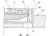
例如在专利文献1等中记载了图20A、图20B所示的结构。For example, the structure shown in FIG. 20A and FIG. 20B is described inpatent document 1 etc. FIG.

其如图20B所示,在分析用盘片201的分析用面板保持部204上安装了分析用面板203的状态下,使图20A所示的该分析用盘片201绕旋转轴心202旋转,对样品液进行光学分析。As shown in FIG. 20B , in a state where theanalysis panel 203 is mounted on the analysispanel holding portion 204 of theanalysis disk 201 , theanalysis disk 201 shown in FIG. 20A is rotated around the rotation axis 202 , The sample liquid is subjected to optical analysis.

在分析用盘片201上可自由装拆的上述分析用面板203包括:样品液的注入口214、与注入口214连通的腔208、以及与腔208连通的空气口210,由于注入口214形成在分析用面板203的端面上,因此容易注入样品液,并且,在分析用盘片201上与分析用面板203的注入口214的位置对应地形成有吸收部件215,吸收部件215适量地吸收附着在分析用面板203的注入口214周围的样品液。另外,在分析用面板203被安装在分析用面板保持部204上的状态下,分析用面板203的注入口214被吸收部件215密闭。The above-mentionedanalysis panel 203 that can be freely assembled and disassembled on theanalysis disk 201 includes: aninjection port 214 of the sample liquid, acavity 208 communicated with theinjection port 214, and anair port 210 communicated with thecavity 208, because theinjection port 214 forms On the end surface of theanalysis panel 203, it is easy to inject the sample liquid, and on theanalysis disc 201, anabsorbing member 215 is formed corresponding to the position of theinjection port 214 of theanalysis panel 203, and the absorbingmember 215 absorbs and adheres to an appropriate amount. The sample liquid around theinjection port 214 of thepanel 203 for analysis. In addition, theinlet 214 of theanalysis panel 203 is sealed by the absorbingmember 215 in a state where theanalysis panel 203 is attached to theanalysis panel holder 204 .

分析用面板203的腔208相对于注入口214和空气口210在分析用盘片位于201外周的位置上形成流路,在腔208的流路的途中涂布了用于与样品液反应的分析试剂209。Thechamber 208 of theanalysis panel 203 forms a flow path at the position where the analysis disk is located on the outer periphery of theanalysis disk 201 with respect to theinjection port 214 and theair port 210, and an analysis agent for reacting with the sample liquid is coated in the middle of the flow path of thechamber 208.Reagent 209.

使用该分析用面板203的分析动作是:在将分析用面板203从分析用盘片201上拆下的状态下,在分析用面板203的注入口214滴注样品液,使样品液通过毛细管力的作用而朝与注入口214连通的腔208内转移。The analysis operation using thisanalysis panel 203 is: in the state where theanalysis panel 203 is detached from theanalysis disk 201, the sample solution is dripped into theinjection port 214 of theanalysis panel 203, and the sample solution is passed through the capillary force. The role of the transfer toward thechamber 208 communicated with theinjection port 214 .

一旦将放置了样品液的分析用面板203安装到分析用盘片201的分析用面板保持部204上,注入口214的开口部便会被分析用盘片201闭锁。此时,附着在注入口214端面上的样品液因与吸收部件215接触而被吸收,因此,可防止样品液附着到与注入口214相对的位置上、在分析用盘片201的旋转中样品液飞散等,可安全地进行以后的样品液的分析试验。When theanalysis panel 203 containing the sample liquid is attached to theanalysis panel holder 204 of theanalysis disk 201 , the opening of theinjection port 214 is closed by theanalysis disk 201 . At this time, the sample liquid adhering to the end surface of theinjection port 214 is absorbed by the contact with the absorbingmember 215, so that the sample liquid can be prevented from adhering to the position opposite to theinjection port 214, and the sample liquid can be prevented from rotating during the rotation of theanalysis disc 201. It can safely carry out the analysis test of the sample liquid later.

专利文献1:日本专利特开2003-185671公报Patent Document 1: Japanese Patent Laid-Open Publication No. 2003-185671

然而,在用吸收部件215来吸引附着在注入口214周围的样品液的场合,被注入到分析用面板203的腔208内的样品液也会被吸收部件215吸引,在与分析试剂209进行混合时,所需的样品液不足,存在会给分析试剂209与样品液的反应状态的测定带来影响的的问题。However, in the case where the absorbingmember 215 is used to suck the sample liquid adhering to theinjection port 214, the sample liquid injected into thecavity 208 of theanalysis panel 203 is also sucked by the absorbingmember 215 and mixed with theanalysis reagent 209. In this case, the required sample liquid is insufficient, which may affect the measurement of the reaction state of theanalytical reagent 209 and the sample liquid.

另外,由于吸收部件215设置在分析用盘片201侧,因此,在反复使用分析用盘片201的场合,每次将分析用面板203安装到分析用盘片201上进行分析时附着在注入口214周围的样品液都会被吸收部件215吸引,因此,吸引部件215会因样品液而逐渐受到污染。这可能会导致在欲测定的样品液中混入被污染的物质而给测定带来不良影响,或导致操作者因与污染的吸收部件215接触而感染疾病等。另外,每次分析时还需要进行将吸收部件215更换成新的或对其进行清洗等费时的操作,也存在很难进行安全管理的问题。In addition, since the absorbingmember 215 is provided on theanalysis disk 201 side, when theanalysis disk 201 is used repeatedly, theanalysis panel 203 is attached to the injection port every time theanalysis panel 203 is attached to theanalysis disk 201 for analysis. The sample liquid around 214 will be attracted by the absorbingmember 215, therefore, the attractingmember 215 will be gradually polluted by the sample liquid. This may cause contamination of the sample liquid to be measured to adversely affect the measurement, or cause the operator to contract a disease due to contact with the contaminatedabsorbent member 215 . In addition, time-consuming operations such as replacing theabsorbent member 215 with a new one or cleaning it are required for each analysis, and there is also a problem that safety management is difficult.

发明内容Contents of the invention

因此,鉴于上述问题,本发明的目的在于提供一种即使在注入口214的周围附着了样品液时也可防止样品液不足或因防止污染等而影响测定的事态发生的分析用面板及使用该面板的分析装置。Therefore, in view of the above-mentioned problems, an object of the present invention is to provide an analysis panel that can prevent the occurrence of a situation where the sample liquid is insufficient or the measurement is affected due to the prevention of contamination even when the sample liquid adheres to the vicinity of theinjection port 214, and the use of the panel. Panel analysis device.

在本发明的技术方案1记载的分析用面板中,在面板本体的一个侧面上设置有样品液的注入口,在上述面板本体的内部设置有与上述注入口连通的室,滴注于上述注入口的样品液朝该室转移,在将上述注入口配置在旋转轴心侧的状态下使上述面板本体旋转,在上述室内进行上述样品液中的成分的分析,其特征在于,上述注入口呈从面板本体的上述一个侧面朝远离室的方向突出的形状,在面板本体的上述一个侧面前面的上述注入口周围形成有凹部。In the analysis panel described inclaim 1 of the present invention, an injection port for the sample liquid is provided on one side of the panel body, and a chamber communicating with the injection port is provided inside the panel body, and the sample liquid is dripped into the injection port. The sample liquid at the inlet is transferred to the chamber, and the panel body is rotated with the injection port arranged on the side of the rotation axis, and the components in the sample liquid are analyzed in the chamber, and the injection port is characterized in that A shape protrudes from the one side surface of the panel body in a direction away from the chamber, and a concave portion is formed around the injection port in front of the one side surface of the panel body.

本发明的技术方案2所述的分析用面板是在技术方案1中,其特征在于,上述注入口的突出量与面板本体的一个侧面大致相同。The analysis panel according toclaim 2 of the present invention is the analysis panel according toclaim 1, wherein the projection amount of the injection port is substantially the same as that of one side surface of the panel body.

本发明的技术方案3所述的分析用面板是在技术方案1中,其特征在于,上述凹部的开口部的截面积的大小大于等于凹部的内端部的截面积。The analysis panel according toclaim 3 of the present invention is the analysis panel according toclaim 1, wherein the cross-sectional area of the opening of the concave portion is greater than or equal to the cross-sectional area of the inner end portion of the concave portion.

本发明的技术方案4所述的分析用面板是在技术方案1中,其特征在于,上述注入口以上述凹部的底面为基端突出形成。According toclaim 4 of the present invention, inclaim 1 , the analysis panel is characterized in that the injection port protrudes from the bottom surface of the concave portion as a base end.

本发明的技术方案5所述的分析用面板是在技术方案1中,其特征在于,上述容积是可收纳在样品液朝上述注入口滴注时附着在上述注入口附近的样品液的大小。The analysis panel according toclaim 5 of the present invention is inclaim 1, wherein the volume is of a size capable of accommodating sample liquid adhering to the vicinity of the injection port when the sample liquid is dripped toward the injection port.

本发明的技术方案6所述的分析用面板是在技术方案1中,其特征在于,在上述凹部内配置有吸收上述样品液的吸收部件。The analysis panel according toclaim 6 of the present invention is the analysis panel according toclaim 1, wherein an absorbing member for absorbing the sample liquid is disposed in the concave portion.

本发明的技术方案7所述的分析用面板是在技术方案6中,其特征在于,将上述吸收部件配置在与因绕上述轴心旋转产生的离心力而转移到凹部内的样品液接触的位置上。The panel for analysis according toclaim 7 of the present invention is inclaim 6, wherein the absorbing member is disposed at a position where it contacts the sample liquid transferred into the recess due to the centrifugal force generated by the rotation around the axis. superior.

本发明的技术方案8所述的分析用面板是在技术方案1中,其特征在于,与上述凹部连通地形成利用毛细管力来保持样品液的槽部。The analysis panel according toclaim 8 of the present invention is inclaim 1, wherein a groove portion for holding a sample liquid by capillary force is formed in communication with the concave portion.

本发明的技术方案9所述的分析用面板是在技术方案8中,其特征在于,上述槽部与凹部的底部连通。According to claim 9 of the present invention, inclaim 8, the panel for analysis is characterized in that the groove portion communicates with the bottom of the concave portion.

本发明的技术方案10所述的分析用面板是在技术方案8中,其特征在于,上述槽部呈使因绕上述轴心旋转产生的离心力而转移到凹部内的样品液在上述离心力的作用下继续朝内部转移的形状。The panel for analysis according to claim 10 of the present invention is inclaim 8, wherein the groove is formed so that the sample liquid transferred into the concave part due to the centrifugal force generated by the rotation around the axis is under the action of the centrifugal force. Next continue to shift the shape towards the inside.

本发明的技术方案11所述的分析用面板是在技术方案1中,其特征在于,上述凹部与上述室连通。The analysis panel according toclaim 11 of the present invention is the analysis panel according toclaim 1, wherein the concave portion communicates with the chamber.

本发明的技术方案12所述的分析用面板是在技术方案11中,其特征在于,将连通上述凹部与上述室的通路构成为:使附着在注入口附近的样品液在绕上述轴心旋转产生的离心力的作用下朝上述室内转移。The panel for analysis according toclaim 12 of the present invention is inclaim 11, wherein the passage connecting the recess and the chamber is configured such that the sample liquid adhering to the vicinity of the injection port is rotated around the axis. Under the action of the generated centrifugal force, it is transferred to the above-mentioned chamber.

本发明的技术方案13所述的分析用面板是在技术方案1中,其特征在于,在与上述注入口连通的上述室内具有在作为样品液的血液的分析中使用的分析试剂。The analysis panel according to claim 13 of the present invention is inclaim 1, wherein an analysis reagent used for analysis of blood as a sample liquid is provided in the chamber communicating with the injection port.

本发明的技术方案14所述的分析用面板是在技术方案1中,其特征在于,具有覆盖上述注入口和上述凹部的可开闭的盖子。According toclaim 14 of the present invention, inclaim 1, the panel for analysis includes an openable and closable cover covering the injection port and the concave portion.

本发明的技术方案15所述的分析用面板是在技术方案1中,其特征在于,具有覆盖上述注入口和上述凹部的可开闭的盖子,在上述盖子的内侧设置有吸收样品液的吸收部件。According toclaim 15 of the present invention, inclaim 1, the panel for analysis is characterized in that it has an openable and closable cover covering the injection port and the recess, and an absorber for absorbing the sample solution is provided inside the cover. part.

本发明的技术方案16所述的分析用面板是在技术方案1中,其特征在于,具有覆盖上述注入口和上述凹部的可开闭的盖子,在上述盖子的内侧设置有吸收样品液的吸收部件,在上述注入口与上述吸收部件之间形成有空隙。The panel for analysis according toclaim 16 of the present invention is inclaim 1, characterized in that it has an openable and closable cover covering the injection port and the recess, and an absorber for absorbing the sample solution is provided inside the cover. A member in which a gap is formed between the inlet and the absorbing member.

本发明的技术方案17所述的分析用面板是在技术方案1中,其特征在于,所述室包括:临时保持被滴注于上述注入口的样品液的保持室;保持分析所需的分析试剂的试剂室;以及测定室区域,被上述保持室保持的样品液和上述分析试剂朝该测定室区域转移,使两者混合,并进行与分析试剂混合后的样品液的测定。The panel for analysis according toclaim 17 of the present invention is inclaim 1, wherein the chamber includes: a holding chamber for temporarily holding the sample liquid dripped into the injection port; a reagent chamber for reagents; and a measurement chamber region toward which the sample liquid held in the holding chamber and the analytical reagent are transferred and mixed, and the sample liquid mixed with the analytical reagent is measured.

本发明的技术方案18所述的分析用面板是在技术方案1、技术方案12、技术方案14的任一个中,其特征在于,在上述注入口的周缘部的表面、上述凹部、连通上述凹部与上述室的通路、上述盖子部件的内表面的至少一个上涂布了表面活化剂。The panel for analysis according toclaim 18 of the present invention is any one ofclaim 1,claim 12, and claim 14, wherein the surface of the peripheral portion of the injection port, the recess, and the recess communicating with the recess are A surfactant is coated on at least one of a passage with the chamber and an inner surface of the lid member.

本发明的技术方案19所述的分析装置包括:分析用面板,在其内部设置有与设置在面板本体的一个侧面上的样品液的注入口连通的室,被滴注于上述注入口的样品液朝该室转移;以及分析用面板保持部件,其供分析用面板进行安装,上述分析装置通过使上述分析用面板保持部件旋转而产生的离心力的作用使滴注于上述注入口的样品液朝室转移,通过以光学方式接触上述室内的样品液,检测出信号,进行分析处理,其特征在于,在上述分析用面板上设置有覆盖上述注入口的可开闭的盖子,上述盖子关闭后的上述分析用面板以上述注入口横切上述分析用面板保持部件的旋转轴心的形态安装在上述分析用面板保持部件上进行分析动作。The analysis device according toclaim 19 of the present invention includes: a panel for analysis, inside which is provided a chamber communicating with a sample solution injection port provided on one side of the panel body, and the sample dripped into the injection port The liquid is transferred toward the chamber; and the analysis panel holding member is installed on the analysis panel, and the analysis device makes the sample liquid dripped into the injection port toward the centrifugal force generated by rotating the analysis panel holding member Chamber transfer, by contacting the sample liquid in the above-mentioned chamber optically, detecting the signal, and performing analysis and processing, it is characterized in that an openable and closable cover covering the above-mentioned injection port is provided on the above-mentioned analysis panel, and after the above-mentioned cover is closed, The analysis panel is attached to the analysis panel holding member in such a manner that the injection port crosses the rotation axis of the analysis panel holding member to perform an analysis operation.

本发明的技术方案20所述的分析装置是在技术方案19中,其特征在于,在上述盖子的内侧设置有吸收样品液的吸收部件。The analysis device according toclaim 20 of the present invention is inclaim 19, wherein an absorbing member for absorbing a sample liquid is provided inside the cover.

本发明的技术方案21所述的分析装置是在技术方案19中,其特征在于,在上述盖子的内侧设置有凹部,该凹部捕捉附着在分析用面板的上述注入口附近的样品液滴。The analysis device according to claim 21 of the present invention, inclaim 19 , is characterized in that a concave portion is provided inside the cover for catching sample liquid droplets adhering to the vicinity of the injection port of the analysis panel.

本发明的技术方案22所述的分析装置是在技术方案21中,其特征在于,在上述凹部形成有利用毛细管力来保持样品液的槽。According toclaim 22 of the present invention, in claim 21, in claim 21, a groove for holding a sample liquid by capillary force is formed in the concave portion.

本发明的技术方案23所述的分析装置是在技术方案19中,其特征在于,在分析用面板的上述注入口的周缘部的表面、上述盖子部件的内表面的至少一个上涂布了表面活化剂。The analysis device according toclaim 23 of the present invention, inclaim 19, is characterized in that at least one of the surface of the peripheral portion of the injection port of the analysis panel and the inner surface of the cover member is coated with a surface activator.

本发明的技术方案24所述的分析装置包括:技术方案1~技术方案8中任一项所述的分析用面板、以及供上述分析用面板进行安装的分析用面板保持部件,上述分析装置通过使上述分析用面板保持部件旋转而产生的离心力的作用使滴注于上述注入口的样品液朝室转移,通过以光学方式接触上述室内的样品液,检测出信号,进行分析处理,其特征在于,将上述分析用面板以上述注入口位于上述分析用面板保持部件的旋转轴心的外周侧、或上述注入口横切上述分析用面板保持部件的旋转轴心的形态安装在上述分析用面板保持部件上进行分析动作。The analysis device according to claim 24 of the present invention includes: the panel for analysis according to any one ofclaims 1 to 8, and an analysis panel holding member for mounting the panel for analysis. The centrifugal force generated by the rotation of the analysis panel holding member transfers the sample solution dripped into the injection port to the chamber, and optically contacts the sample solution in the chamber to detect a signal and carry out analysis processing, characterized in that The above-mentioned analysis panel is mounted on the above-mentioned analysis panel holder in such a manner that the above-mentioned injection port is located on the outer peripheral side of the rotation axis of the above-mentioned analysis panel holding member, or the above-mentioned injection port crosses the rotation axis of the above-mentioned analysis panel holding member. Perform analysis actions on components.

在本发明的技术方案25所述的分析用面板中,在面板本体的一个侧面上设置有样品液的注入口,在上述面板本体的内部设置有与上述注入口连通的室,被滴注于上述注入口的样品液朝该室转移,通过使上述面板本体绕轴心旋转,在上述室内进行上述样品液中的成分的分析,其特征在于,上述注入口呈从面板本体的上述一个侧面朝着远离室的方向突出的形状,在上述面板本体上设置有覆盖上述注入口的可开闭的盖子,在上述盖子的内侧设置有对附着在上述注入口附近的样品液滴进行捕捉的凹部或吸收上述样品液滴的吸收部件,在上述盖子被关闭的状态下,在上述注入口与上述凹部之间、或上述注入口与上述吸收部件之间形成有空隙。In the panel for analysis according to claim 25 of the present invention, an injection port for sample liquid is provided on one side of the panel body, and a chamber communicating with the injection port is provided inside the panel body, and is dripped into The sample liquid in the injection port is transferred to the chamber, and the components in the sample liquid are analyzed in the chamber by rotating the panel body around the axis. In a shape protruding away from the chamber, an openable and closable cover covering the injection port is provided on the panel body, and a concave portion or a recess for catching sample droplets adhering to the vicinity of the injection port is provided on the inner side of the cover. The absorbent member for absorbing the sample droplet has a gap formed between the injection port and the concave portion, or between the injection port and the absorbent member in a state where the cover is closed.

发明效果Invention effect

在本发明的分析用面板中,设置在面板本体的一个侧面上的注入口呈从面板本体的上述一个侧面朝着远离室的方向突出的形状,且在面板本体的上述一个侧面前面的上述注入口周围形成有凹部,因此,当在将上述注入口配置在旋转轴心侧的状态下使上述面板本体旋转、在上述室内进行上述样品液中的成分的分析时,一旦产生离心力,附着在注入口周围的样品液便会可靠地朝凹部转移而被收集,可防止被注入到室内的样品液朝室外反方向地放出。In the analysis panel of the present invention, the injection port provided on one side of the panel body has a shape protruding from the one side of the panel body toward a direction away from the chamber, and the injection port in front of the one side of the panel body is Since a concave portion is formed around the inlet, when the panel body is rotated with the injection port disposed on the side of the rotation axis, and components in the sample liquid are analyzed in the chamber, once centrifugal force is generated, adhering to the injection port The sample liquid around the inlet is reliably transferred to the concave portion and collected, and the sample liquid injected into the chamber is prevented from being discharged in the opposite direction to the outside.

另外,本发明的分析装置包括:分析用面板,在其内部设置有与设置在面板本体的一个侧面上的样品液的注入口连通的室,被滴注于上述注入口的样品液朝该室转移;以及分析用面板保持部件,其供分析用面板进行安装,上述分析装置通过使上述分析用面板保持部件旋转而产生的离心力的作用使滴注于上述注入口的样品液朝室转移,通过以光学方式接触上述室内的样品液,检测出信号,进行分析处理,在上述分析用面板上设置有覆盖上述注入口的可开闭的盖子,上述盖子关闭后的上述分析用面板以上述注入口横切上述分析用面板保持部件的旋转轴心的形态安装在上述分析用面板保持部件上进行分析动作,因此,一旦上述分析用面板保持部件旋转而产生离心力,滴注于注入口的样品液便会朝上述室转移。另外,在上述滴注时附着在注入口周围的样品液朝着与室相反的方向移动而被上述盖子可靠地收集,可防止其朝外部飞散而产生污染。In addition, the analysis device of the present invention includes: a panel for analysis, in which a chamber communicating with a sample liquid injection port provided on one side of the panel body is provided, and the sample liquid dripped into the above-mentioned injection port flows toward the chamber. transfer; and an analysis panel holding member, which is used for installing the analysis panel, and the above-mentioned analysis device transfers the sample liquid dripped into the above-mentioned injection port toward the chamber by the action of the centrifugal force generated by rotating the above-mentioned analysis panel holding member. The sample liquid in the above-mentioned chamber is optically contacted, a signal is detected, and an analysis process is performed. An openable and closable cover covering the above-mentioned injection port is provided on the above-mentioned analysis panel, and the above-mentioned analysis panel with the above-mentioned injection port after the cover is closed Since the analysis operation is performed by attaching to the analysis panel holding member so as to cross the rotation axis of the analysis panel holding member, the sample liquid dripped into the injection port will be Will move towards the above chamber. In addition, the sample liquid adhering to the periphery of the injection port during the instillation moves in a direction opposite to the chamber and is reliably collected by the cap, preventing it from scattering to the outside and causing contamination.

附图说明Description of drawings

图1是本发明实施形态1的分析用面板的外观立体图。Fig. 1 is an external perspective view of an analysis panel according toEmbodiment 1 of the present invention.

图2是上述实施形态的分析用面板的分解立体图。Fig. 2 is an exploded perspective view of the analysis panel of the above embodiment.

图3是上述分析用面板被安装在分析装置的分析用面板保持部件上的状态的立体图。Fig. 3 is a perspective view of a state in which the analysis panel is attached to an analysis panel holding member of the analysis device.

图4是上述实施形态的分析用面板的注入口周围的放大立体图。Fig. 4 is an enlarged perspective view of the surroundings of the injection port of the analysis panel of the above embodiment.

图5是上述实施形态的分析装置的结构图。Fig. 5 is a configuration diagram of the analyzer of the above-mentioned embodiment.

图6是表示在上述分析用面板上安装了可开闭的盖子的例子的外观立体图。Fig. 6 is an external perspective view showing an example in which an openable and closable cover is attached to the analysis panel.

图7是本发明实施形态2的分析用面板的注入口周围的放大剖视图。Fig. 7 is an enlarged cross-sectional view around an injection port of an analysis panel according toEmbodiment 2 of the present invention.

图8A是上述实施形态的样品液滴的转移工序的说明图。Fig. 8A is an explanatory diagram of a sample liquid droplet transfer step in the above embodiment.

图8B是上述实施形态的样品液滴的转移工序的说明图。Fig. 8B is an explanatory diagram of the sample liquid droplet transfer step in the above embodiment.

图9是本发明实施形态3的分析用面板的注入口周围的放大剖视图。Fig. 9 is an enlarged cross-sectional view around the injection port of the analysis panel according toEmbodiment 3 of the present invention.

图10A是上述实施形态的样品液滴的转移工序的说明图。Fig. 10A is an explanatory diagram of a sample liquid droplet transfer step in the above embodiment.

图10B是上述实施形态的样品液滴的转移工序的说明图。Fig. 10B is an explanatory diagram of the sample liquid droplet transfer step in the above embodiment.

图10C是上述实施形态的样品液滴的转移工序的说明图。Fig. 10C is an explanatory diagram of the sample droplet transfer step in the above embodiment.

图11是本发明实施形态4的分析用面板的注入口周围的放大剖视图。Fig. 11 is an enlarged cross-sectional view around an injection port of an analysis panel according toEmbodiment 4 of the present invention.

图12A是上述实施形态的样品液滴的转移工序的说明图。Fig. 12A is an explanatory diagram of a sample liquid droplet transfer step in the above embodiment.

图12B是上述实施形态的样品液滴的转移工序的说明图。Fig. 12B is an explanatory view of the sample droplet transfer step in the above embodiment.

图12C是上述实施形态的样品液滴的转移工序的说明图。Fig. 12C is an explanatory diagram of the sample droplet transfer step in the above embodiment.

图13是本发明实施形态5的分析用面板的外观立体图。Fig. 13 is an external perspective view of an analysis panel according toEmbodiment 5 of the present invention.

图14是表示上述实施形态的分析用面板在分析装置上的安装位置的立体图。Fig. 14 is a perspective view showing the mounting position of the analysis panel of the above embodiment on the analysis device.

图15是上述分析用面板被安装在分析装置上时注入口周围的剖视图。Fig. 15 is a cross-sectional view around the injection port when the analysis panel is attached to the analysis device.

图16是本发明实施形态6的分析用面板的盖子被打开的外观立体图。Fig. 16 is a perspective view showing the appearance of an analysis panel according toEmbodiment 6 of the present invention with its cover opened.

图17是在上述实施形态的盖子被关闭的状态下透视盖子的立体图。Fig. 17 is a perspective view through which the cover of the above embodiment is closed in a state where the cover is seen through.

图18是上述分析用面板被安装在分析装置上时注入口周围的剖视图。Fig. 18 is a cross-sectional view around the injection port when the analysis panel is attached to the analysis device.

图19A是另一実施例的注入口周围的剖视图。Fig. 19A is a cross-sectional view around an injection port of another example.

图19B是从注入口看盖子的主视图。Fig. 19B is a front view of the cap viewed from the inlet.

图19C是盖子的水平剖视图。Fig. 19C is a horizontal sectional view of the cover.

图20A是以往的分析用面板被安装在分析用面板保持部上时的整体立体图。Fig. 20A is an overall perspective view of a conventional analysis panel mounted on an analysis panel holder.

图20B是以往的分析用面板和分析用面板保持部分开时的立体图。FIG. 20B is a perspective view of a conventional analysis panel and an analysis panel holding portion separated from each other.

具体实施方式Detailed ways

下面参照图1~图19A、图19B、图19C来说明本发明的各实施形态。Next, various embodiments of the present invention will be described with reference to FIGS. 1 to 19A, 19B, and 19C.

(实施形态1)(Embodiment 1)

图1~图6表示了本发明的实施形态1。1 to 6show Embodiment 1 of the present invention.

图1表示了本发明的分析用面板3,图2是其分解图。FIG. 1 shows ananalysis panel 3 of the present invention, and FIG. 2 is an exploded view thereof.

分析用面板3由上部基板1和下部基板2贴合而成,在下部基板2的一个面上形成有:形成注入口14的一个面15;保持被注入注入口14的样品液的保持室4;保持着分析试剂(未图示)的试剂室5;测定室区域7,被保持室5保持的样品液和分析试剂朝其转移,其使两者混合,并进行与分析试剂混合后的样品液的测定;使试剂室5与测定室区域7连通的流路6;以及使测定室区域7与大气开放孔9连通的流路8。Theanalysis panel 3 is formed by laminating theupper substrate 1 and thelower substrate 2, and on one surface of thelower substrate 2 are formed: asurface 15 forming theinjection port 14; a holdingchamber 4 for holding the sample liquid injected into theinjection port 14 ;Reagent chamber 5 holding an analysis reagent (not shown); Measuringchamber area 7, the sample liquid and analysis reagent held by the holdingchamber 5 are transferred to it, and it makes the two mix, and the sample mixed with the analysis reagent is carried out. measurement of the liquid; theflow path 6 connecting thereagent chamber 5 and themeasurement chamber area 7;

另外,在本实施形态中,将使样品液与分析试剂混合的室和进行与分析试剂混合后的样品液的测定的室作为一体型的测定室区域7构成,但也可分开形成使样品液与分析试剂混合的室和进行与分析试剂混合后的样品液的测定的室。In addition, in the present embodiment, the chamber for mixing the sample liquid and the analytical reagent and the chamber for measuring the sample liquid mixed with the analytical reagent are configured as an integratedmeasurement chamber region 7, but it may be formed separately so that the sample liquid A chamber for mixing the analytical reagent and a chamber for measuring the sample liquid mixed with the analytical reagent.

在下部基板2上贴合上部基板1,封闭保持室4、试剂室5、测定室区域7、流路6及流路8的各开口面,从而形成具有规定大小的间隙的空洞,发挥利用毛细管力使样品液转移或保持规定量的液量等各种功能。注入口14通过接合下部基板2的一个面15和上部基板1的一个面16而形成。Theupper substrate 1 is attached to thelower substrate 2, and the opening surfaces of the holdingchamber 4, thereagent chamber 5, themeasurement chamber area 7, theflow path 6, and theflow path 8 are sealed to form a cavity with a gap of a predetermined size, and to utilize the capillary. Various functions such as transferring the sample liquid or maintaining a predetermined amount of liquid by force.Injection port 14 is formed by joining onesurface 15 oflower substrate 2 and onesurface 16 ofupper substrate 1 .

图3表示的是该分析用面板3被安装在分析装置的分析用面板保持部件101上的状态。分析装置一边利用旋转驱动装置使呈盘片状的分析用面板保持部件101以轴心11为中心进行旋转,一边以光学方式对上述样品液的特性进行分析。FIG. 3 shows a state where theanalysis panel 3 is attached to the analysispanel holding member 101 of the analyzer. The analysis device optically analyzes the properties of the sample liquid while rotating the disk-shaped analysispanel holding member 101 around theaxis 11 by a rotary drive device.

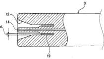
如图4所示,分析用面板3的注入口14朝远离保持室4的方向突出形成。即,分析用面板3的注入口14形成为在将分析用面板3放置在分析用面板保持部件101上的状态下朝着比分析用面板3的本体的一个侧面更靠近上述轴心11的方向突出的形状,样品液容易进行供给。具体而言,在采集人体的血液并将其作为样品液放置时,将作为采血用穿刺辅助件的刺血针等穿刺针压靠在指尖等采血部位上并穿刺,使注入口14与采血部位接触进行采血,从而使样品液通过毛细管力等的作用注入到保持室4内,可容易地供给样品液,滴注时可防止血液附着到注入口14以外的位置上。As shown in FIG. 4 , theinlet 14 of theanalysis panel 3 protrudes in a direction away from the holdingchamber 4 . That is, theinlet 14 of theanalysis panel 3 is formed in a direction closer to theaxis 11 than one side of the main body of theanalysis panel 3 in a state where theanalysis panel 3 is placed on the analysispanel holding member 101. The protruding shape makes it easy to supply sample liquid. Specifically, when collecting blood from a human body and placing it as a sample liquid, a puncture needle such as a lancet as a puncture aid for blood collection is pressed against a blood collection site such as a fingertip and punctures, and theinjection port 14 is connected to the blood collection site. Blood sampling is performed by contacting the parts, so that the sample solution is injected into the holdingchamber 4 by the action of capillary force, etc., the sample solution can be easily supplied, and blood can be prevented from adhering to positions other than theinjection port 14 during instillation.

图5表示了分析装置的结构。Fig. 5 shows the structure of the analyzing device.

本分析装置包括:供分析用面板3进行安装的分析用面板保持部件101;驱动分析用面板保持部件101绕轴心11旋转的作为旋转驱动装置的电动机102;用于对分析用面板3内的溶液进行光学测定的光学测定装置104;对分析用面板保持部件101的旋转速度或旋转方向、以及光学测定装置104的测定时间等进行控制的控制装置105;运算部106,它对由光学测定装置104得到的信号进行处理,在样品液为血液时,除了血液中的特定物质的浓度或量之外,还根据分析目的对物质的形状、大小等进行运算;以及用于显示由运算部106得到的结果的显示部107。This analyzing device comprises: thepanel holding part 101 for analysis that thepanel 3 is installed for analysis; An optical measuring device 104 for optically measuring the solution; a control device 105 for controlling the rotational speed or direction of rotation of thepanel holding member 101 for analysis, and the measurement time of the optical measuring device 104; 104 to process the signal obtained. When the sample liquid is blood, in addition to the concentration or amount of the specific substance in the blood, the shape and size of the substance are also calculated according to the purpose of analysis; The display section 107 of the result.

光学测定装置104包括:用于对分析用面板3的测定部照射激光的激光光源103、以及对从激光光源103照射来的激光中透过了分析用设备1的透射光的光量进行检测的光检测器108,可设置与测定所需的波长的种类对应的激光光源103和光检测器108。The optical measurement device 104 includes: a laser light source 103 for irradiating laser light to the measurement portion of theanalysis panel 3 ; The detector 108 may be provided with a laser light source 103 and a photodetector 108 corresponding to the type of wavelength required for measurement.

该分析装置根据其用途,还可成为利用分析用面板3内的室和流路的结构、使用绕轴心旋转产生的离心力来转移或离心分离面板内的液体的离心分离机。分析用面板的形状也可以是扇形形状、立方体形状或其它形状,另外,这些分析用面板3也可多个同时安装到分析用面板保持部件101上。Depending on the application, this analysis device can also be a centrifuge that transfers or centrifuges the liquid in thepanel 3 by utilizing the structure of the chamber and the flow path in theanalysis panel 3 and using the centrifugal force generated by the rotation around the axis. The shape of the analysis panel may be a fan shape, a cube shape, or other shapes, and a plurality of theseanalysis panels 3 may be attached to the analysispanel holding member 101 at the same time.

如放大表示注入口14的周边部的图4所示,在分析用面板3一侧面的注入口14的周围,仅上述轴心11侧开口,并且形成有从轴心11朝外周方向凹陷的凹部12。凹部12形成为缓缓弯曲的形状,以使轴心11侧的开口部的截面积成为大于等于凹部12外周侧的开口部的截面积的大小,因此,当在图3所示的状态下产生离心力时,附着在注入口14周围的样品液能可靠地朝凹部12转移,并容易进一步朝凹部12的最低位置转移,可在不朝凹部12外飞散的情况下进行收集。As shown in FIG. 4 which enlargedly shows the peripheral portion of theinjection port 14, around theinjection port 14 on one side surface of theanalysis panel 3, only theaxis 11 side is open, and a recess is formed that is depressed from theaxis 11 toward the outer periphery. 12. Therecess 12 is formed in a gently curved shape so that the cross-sectional area of the opening on the side of theaxis 11 becomes greater than or equal to the cross-sectional area of the opening on the outer peripheral side of therecess 12. Therefore, when the state shown in FIG. 3 occurs Under the centrifugal force, the sample liquid adhering to theinjection port 14 can be reliably transferred to therecess 12, and further transferred to the lowest position of therecess 12, and can be collected without being scattered outside therecess 12.

另外,通过以从该开口的凹部12的底面朝靠近轴心11的方向突出的形态利用上述一个面15、16形成了注入口14的突起状,附着在注入口14周围的样品液会朝凹部12内转移,但由于转移至的位置是凹部12内的大致底面,因此,样品液不会从凹部12内溢出,可稳定地进行收集,此外,还具有可用一个凹部12进行收集的效果。In addition, since theinjection port 14 protrudes from the bottom surface of theopening recess 12 in a direction close to theaxis 11 by using the above-mentioned onesurface 15, 16 to form a protrusion shape of theinjection port 14, the sample liquid adhering to the vicinity of theinjection port 14 will flow toward the recess. 12, but since the transferred position is approximately the bottom surface in therecess 12, the sample liquid will not overflow from therecess 12 and can be collected stably. In addition, it also has the effect of collecting with onerecess 12.

即,附着在注入口14附近的样品液因绕轴心旋转产生的离心力而沿着形成注入口14的突起部的表面传递,朝凹部12内转移。此时,在附着在注入口14附近的样品液朝凹部12内转移的同时,保持室4内的样品液因离心力而朝预先载有分析试剂的试剂室5内转移。流入试剂室5内的液体样品因分析用面板保持部件101的旋转加速度形成的晃动或旋转停止时液体的扩散,而与试剂室5内载有的分析试剂混合,但也可施加使试剂室5自身直接振动的外力来进行混合。That is, the sample liquid adhering to the vicinity of theinjection port 14 is transmitted along the surface of the protrusion forming theinjection port 14 by the centrifugal force generated by the rotation around the axis, and transferred into therecess 12 . At this time, while the sample solution adhering to the vicinity of theinjection port 14 is transferred into theconcave portion 12, the sample solution in the holdingchamber 4 is transferred into thereagent chamber 5 loaded with the analysis reagent in advance by centrifugal force. The liquid sample flowing into thereagent chamber 5 is mixed with the analysis reagent carried in thereagent chamber 5 due to the shaking caused by the rotational acceleration of the analysispanel holding member 101 or the diffusion of the liquid when the rotation stops. The external force of its own direct vibration is used for mixing.

在分析试剂与样品液的混合达到规定程度时,试剂室5内的样品液通过毛细管力的作用经由流路6内而转移至测定室区域7的入口。从激光光源103照射来的激光透过测定室区域7,通过用光检测器108对样品液与分析试剂的反应状态进行吸光度测定,可测定其成分的浓度。When the analysis reagent and the sample liquid are mixed to a predetermined level, the sample liquid in thereagent chamber 5 is transferred to the inlet of themeasurement chamber region 7 through theflow path 6 by the action of capillary force. The laser light irradiated from the laser light source 103 passes through themeasurement chamber region 7, and by measuring the absorbance of the reaction state of the sample liquid and the analysis reagent with the photodetector 108, the concentration of the component can be measured.

另外,通过将凹部12的容积形成为可收纳在样品液朝注入口14滴注时附着在注入口14附近的样品液的大小,具有可防止从凹部12内溢出的容积大小的样品液被转移的效果。考虑到血液被用作样品液,当在使用刺血针等穿刺装置进行指尖采血的过程中进行滴注时,推测样品液的量为大致10μl左右,一般从注入口14注入不超过这一滴注量范围的采血量,因此,将凹部12的容积设定成最大为10μl。In addition, by forming the volume of therecess 12 to a size that can accommodate the sample liquid that adheres to the vicinity of theinjection port 14 when the sample liquid is dripped toward theinjection port 14, the sample liquid having a volume that can prevent overflow from therecess 12 is transferred. Effect. Considering that blood is used as a sample liquid, when instilling during fingertip blood collection using a puncture device such as a lancet, it is estimated that the amount of sample liquid is about 10 μl, and it is generally injected from theinjection port 14 not exceeding this amount. Therefore, the volume of therecess 12 is set to a maximum of 10 μl for the amount of blood collected in the instillation volume range.

另外,如图6所示,通过在分析用面板3上设置覆盖注入口14和凹部12的可开闭的盖子18,还可获得如下效果。In addition, as shown in FIG. 6 , by providing an openable andclosable cover 18 covering theinjection port 14 and theconcave portion 12 on theanalysis panel 3 , the following effects can also be obtained.

将上述盖子18打开,朝注入口14滴注样品液,之后,在盖子18被关闭的状态将分析用面板3安装到分析用面板保持部件101上,由此,即使被转移到凹部12的样品液或被转移到室4内的样品液受到某种影响而朝注入口14和凹部12附近的分析用面板3的侧面流出,也会被盖子18挡住,可防止其被释放到外部的事态发生。另外,在分析后,通过在不打开盖子18的情况下直接抛弃,可防止产生污染,适用于一次性的分析用面板。Thecover 18 is opened, the sample liquid is dripped toward theinjection port 14, and then theanalysis panel 3 is mounted on the analysispanel holding member 101 in the state where thecover 18 is closed. The liquid or the sample liquid transferred to thechamber 4 is affected by some influence and flows out toward the side of theanalysis panel 3 near theinjection port 14 and therecess 12, and is also blocked by thecover 18 to prevent it from being released to the outside. . In addition, after the analysis, it is suitable for a disposable analysis panel by directly discarding it without opening thelid 18 to prevent contamination.

另外,在注入口14的周边部的表面上涂布了表面活化剂的场合,在利用上述离心力使样品液朝凹部12转移时,通过对注入口14周边部的表面上的表面活化剂进行亲水性处理,可使样品液顺利地转移。In addition, when the surface of the peripheral portion of theinjection port 14 is coated with a surfactant, when the sample liquid is transferred to theconcave portion 12 by the above-mentioned centrifugal force, the surface active agent on the surface of the peripheral portion of theinjection port 14 is subjected to affinity. Aqueous treatment can make the sample liquid transfer smoothly.

像这样,在注入口14的周围形成有凹部12,因此,可在不存在因附着于注入口14附近的样品液飞散而产生污染的情况下进行分析,另外,还可防止被注入到室4内的样品液朝室外反向地放出。In this way, since theconcave portion 12 is formed around theinjection port 14, the analysis can be performed without contamination due to scattering of the sample liquid adhering to the vicinity of theinjection port 14, and it can also be prevented from being injected into thechamber 4. The sample liquid in the chamber is released reversely toward the outside.

(实施形态2)(Embodiment 2)

图7和图8A、图8B表示了本发明的实施形态2。7 and 8A and8B show Embodiment 2 of the present invention.

另外,由于分析用面板3的主要结构、供分析用面板3进行安装的分析用面板保持部件101以及样品液与分析试剂的反应状态的测定方法与实施形态1中说明的内容相同,因此在此省略其说明。In addition, since the main structure of theanalysis panel 3, the analysispanel holding member 101 for installing theanalysis panel 3, and the method of measuring the reaction state of the sample liquid and the analysis reagent are the same as those described inEmbodiment 1, they are described here. Its description is omitted.

图7表示了实施形态2的分析用面板3的注入口14附近的结构。FIG. 7 shows the structure near theinjection port 14 of theanalysis panel 3 according to the second embodiment.

注入口14的前端位于与分析用面板3的本体的一个侧面大致相同的位置,在注入口14的周围,仅上述轴心11侧的面开口,并且形成有从轴心11朝外周方向凹陷的凹部12。另外,凹部12形成为使凹部12的轴心11侧的开口部的截面积成为大于等于凹部12外周侧的开口部的截面积的大小。另外,注入口14从凹部12的底面突出形成,凹部12的容积构成为可收纳在样品液朝注入口14滴注时附着在注入口附近的样品液滴的大小。在此,使用刺血针等穿刺装置进行一次指尖采血时可滴注的量其极限为10μl左右,一般从注入口14注入不超过该滴注量范围的采血量。基于这种考虑,在本发明中将凹部12的容量设定成最大为10μl。The front end of theinjection port 14 is located at approximately the same position as one side surface of the main body of theanalysis panel 3. Around theinjection port 14, only the surface on the side of theaxis 11 is open, and a groove is formed that is recessed from theaxis 11 toward the outer peripheral direction.Recess 12. In addition, therecess 12 is formed such that the cross-sectional area of the opening on the side of theaxis 11 of therecess 12 is greater than or equal to the cross-sectional area of the opening on the outer peripheral side of therecess 12 . Theinjection port 14 protrudes from the bottom surface of therecess 12 , and the volume of therecess 12 is configured to be large enough to accommodate a sample liquid droplet adhering to the vicinity of theinjection port 14 when the sample liquid is dripped into theinjection port 14 . Here, the limit of the amount that can be instilled when one fingertip blood collection is performed with a puncture device such as a lancet is about 10 μl, and the blood collection amount that does not exceed the range of the infusion amount is generally injected from theinjection port 14 . Based on this consideration, in the present invention, the capacity of therecess 12 is set to be 10 μl at the maximum.

另外,在凹部12内设置有由作为吸收样品液的材料的、例如聚丙烯或纸材料构成的无纺布等吸收部件22。In addition, an absorbingmember 22 made of, for example, polypropylene or paper material, such as a nonwoven fabric, which is a material for absorbing a sample liquid, is provided in therecess 12 .

由于这样构成,因此,在将样品液滴注到注入口14而供给了样品液的状态下,如图8A所示,在注入口14的附近会附着样品液滴19。将附着有样品液滴19的分析用面板3直接安装到分析用面板保持部件101上,利用绕轴心11旋转而产生的离心力,使附着在注入口14附近的样品液滴在凹部12内朝箭头20的方向移动并转移至吸收部件22,最终如图8B所示,使其被吸收部件22吸引。With such a configuration, when the sample liquid is dripped into theinjection port 14 and the sample liquid is supplied, as shown in FIG. 8A , the sampleliquid droplet 19 adheres to the vicinity of theinjection port 14 . Theanalysis panel 3 to which thesample droplet 19 is attached is directly installed on the analysispanel holding member 101, and the sample droplet attached near theinjection port 14 is made to flow in theconcave portion 12 towards the The direction of thearrow 20 moves and transfers to theabsorbent member 22, and finally, it is attracted by theabsorbent member 22 as shown in FIG. 8B.

在配置了吸收样品液的吸收部件22的状态下,通过直接利用转移面板本体内部的样品液时使用的规定的离心力的作用,使附着在注入口附近的样品液朝凹部12转移,另外,设置在注入口外周侧的吸收部件22可对转移来的附着在注入口附近的样品液进行吸收、收集,因此,与没有吸收部件22时相比,收集效果更好。In the state where the absorbingmember 22 for absorbing the sample liquid is arranged, the sample liquid adhering to the vicinity of the injection port is transferred to therecess 12 by directly utilizing the predetermined centrifugal force used when transferring the sample liquid inside the panel body. The absorbingmember 22 on the outer peripheral side of the injection port can absorb and collect the transferred sample liquid adhering to the vicinity of the injection port. Therefore, the collection effect is better than that without the absorbingmember 22 .

在分析用面板3中注入了规定量的样品液后将其安装到分析用面板保持部件101上、进行样品液滴的转移时所需的转速需要是1000rpm以上,但在用表面活化剂等对凹部12的整个内周面和注入口14附近进行了亲水性处理时,只需使由几百rpm的旋转而形成的离心力起作用,就可使样品液滴转移。After injecting a predetermined amount of sample liquid into theanalysis panel 3 and attaching it to the analysispanel holding member 101 to transfer the sample droplet, the rotation speed required is 1000 rpm or more. When the entire inner peripheral surface of theconcave portion 12 and the vicinity of theinjection port 14 are hydrophilically treated, the sample droplet can be transferred only by applying the centrifugal force generated by the rotation of several hundred rpm.

另外,吸收部件22既可设置在凹部12的底面上,也可设置在注入口14与凹部12的底面之间。In addition, the absorbingmember 22 may be provided on the bottom surface of the recessedpart 12 or may be provided between theinjection port 14 and the bottom face of the recessedpart 12 .

另外,通过设置吸收部件22,一旦保持在吸收部件22上的样品液滴19即使在分析结束后吸收部件22朝重力的作用方向倾斜也可不会朝吸收部件22外漏出。In addition, by providing the absorbingmember 22, thesample liquid droplets 19 once held on the absorbingmember 22 do not leak out of the absorbingmember 22 even if the absorbingmember 22 tilts in the direction of gravity after the analysis is completed.

另外,与实施形态1时一样,在分析用面板3上设置上述盖子18,将盖子18打开,朝注入口14滴注样品液,之后,在盖子18被关闭的状态下将分析用面板3安装到分析用面板保持部件101上,由此可进一步提高防止样品液流出的可靠性。In addition, as inEmbodiment 1, the above-mentionedcover 18 is provided on theanalysis panel 3, thecover 18 is opened, and the sample solution is dripped toward theinjection port 14, and then theanalysis panel 3 is attached with thecover 18 closed. To the analysispanel holding member 101, the reliability of preventing the sample liquid from flowing out can be further improved.

(实施形态3)(Embodiment 3)

图9和图10A、图10B、图10C表示了本发明的实施形态3。9 and 10A, 10B, and10C show Embodiment 3 of the present invention.

在实施形态2中,在凹部12内的底面上、或者注入口14与凹部12内的底面之间设置有吸收部件22,在该实施形态3中,唯一的不同点在于设置有与凹部12连通的槽部17、利用毛细管力来保持样品液滴19,其它结构与实施形态2相同。InEmbodiment 2, an absorbingmember 22 is provided on the bottom surface of therecess 12 or between theinjection port 14 and the bottom surface of therecess 12. InEmbodiment 3, the only difference is that a Thegroove portion 17 uses capillary force to hold the sampleliquid droplet 19, and other structures are the same as those in the second embodiment.

图9表示了实施形态3的分析用面板3的注入口14附近的结构。Fig. 9 shows the structure near theinjection port 14 of theanalysis panel 3 according to the third embodiment.

注入口14的前端位于与分析用面板3的本体的一个侧面大致相同的位置,在注入口14的周围,仅上述轴心11侧的面开口,并且形成有从轴心11朝外周方向凹陷的凹部12。另外,凹部12形成为使凹部12的轴心11侧的开口部的截面积成为大于等于凹部12外周侧的开口部的截面积的大小。另外,注入口14从凹部12的底面突出形成,凹部12的容积构成为可收纳在样品液朝注入口14滴注时附着在注入口附近的样品液滴的大小。在凹部12的底面上形成有与凹部12连通的一个以上的槽部17。The front end of theinjection port 14 is located at approximately the same position as one side surface of the main body of theanalysis panel 3. Around theinjection port 14, only the surface on the side of theaxis 11 is open, and a groove is formed that is recessed from theaxis 11 toward the outer peripheral direction.Recess 12. In addition, therecess 12 is formed such that the cross-sectional area of the opening on the side of theaxis 11 of therecess 12 is greater than or equal to the cross-sectional area of the opening on the outer peripheral side of therecess 12 . Theinjection port 14 protrudes from the bottom surface of therecess 12 , and the volume of therecess 12 is configured to be large enough to accommodate a sample liquid droplet adhering to the vicinity of theinjection port 14 when the sample liquid is dripped into theinjection port 14 . One ormore grooves 17 communicating with therecess 12 are formed on the bottom surface of therecess 12 .

由于这样构成,因此,在将样品液滴注到注入口14而供给了样品液的状态下,如图10A所示,在注入口14的附近会附着样品液滴19。将附着有样品液滴19的分析用面板3直接安装到分析用面板保持部件101上,利用绕轴心11旋转而产生的离心力,使附着在注入口14附近的样品液滴如图10B所示地在凹部12内朝箭头20的方向移动、转移至凹部12内的槽部17跟前的位置,最终如图10C所示,使其转移至槽部17的内部并收集于此。With such a configuration, when the sample liquid is dripped into theinjection port 14 and the sample liquid is supplied, as shown in FIG. 10A , the sampleliquid droplet 19 adheres to the vicinity of theinjection port 14 . Theanalysis panel 3 to which thesample droplet 19 is attached is directly mounted on the analysispanel holding member 101, and the sample droplet attached near theinjection port 14 is made by utilizing the centrifugal force generated by the rotation around theaxis 11, as shown in FIG. 10B . The ground moves in the direction of thearrow 20 in therecess 12, transfers to the position in front of thegroove 17 in therecess 12, and finally transfers to the inside of thegroove 17 as shown in FIG. 10C and collects it there.

即,通过与凹部12连续地设置槽部17,朝凹部12转移来的样品液滴19因离心力而继续朝槽部17的内部转移,在槽部17的内部被毛细管力保持。由于样品液滴被毛细管力保持,因此,在之后的没有离心力的状态下,也可防止样品液朝外部溢出。That is, by providing thegroove portion 17 continuously with theconcave portion 12 , thesample droplet 19 transferred to theconcave portion 12 is continuously transferred to the inside of thegroove portion 17 due to the centrifugal force, and is held in thegroove portion 17 by capillary force. Since the sample liquid droplet is held by the capillary force, the sample liquid can be prevented from overflowing to the outside even in a subsequent state where there is no centrifugal force.

像这样,通过直接利用转移样品液时使用的规定离心力的作用,能将样品液滴19可靠地收集到槽部17内,因此,可防止样品液朝分析用面板3外飞散,可在不被污染的情况下进行分析。In this way, by directly using the action of the predetermined centrifugal force used when transferring the sample liquid, the sampleliquid droplet 19 can be reliably collected in thegroove portion 17, so that the sample liquid can be prevented from flying out of theanalysis panel 3, and the sample liquid can be collected without being disturbed. Analyze in case of contamination.

另外,通过将槽部17形成在作为凹部12的样品收容部的最外周侧的底部,可在更远离注入口14的位置上捕获全部朝凹部12转移来的样品液滴19。In addition, by forming thegroove portion 17 at the bottom of the outermost peripheral side of the sample holding portion of therecess 12 , all thesample droplets 19 that have migrated to therecess 12 can be captured at a position farther from theinjection port 14 .

另外,该实施形态3的槽部17的截面形状形成为长方形状,但也可以是圆形、三角形或多边形等其它形状。无论在哪种情况下,为了当分析用面板3在分析结束后从分析用面板保持部件101上拆下而朝重力方向倾斜时槽部17内的样品液也不会掉落,槽部17在轴心11侧的开口部21的厚度d形成为1mm以下。In addition, the cross-sectional shape of thegroove portion 17 in the third embodiment is formed in a rectangular shape, but other shapes such as a circle, a triangle, or a polygon may also be used. In any case, in order to prevent the sample liquid in thegroove portion 17 from falling when theanalysis panel 3 is detached from the analysispanel holding member 101 after the analysis and tilted in the direction of gravity, thegroove portion 17 is placed The thickness d of the opening 21 on theaxial center 11 side is formed to be 1 mm or less.

另外,与实施形态1时一样,将上述盖子18设置在分析用面板3上,将盖子18打开,朝注入口14滴注样品液,之后,在盖子18被关闭的状态将分析用面板3安装到分析用面板保持部件101上,由此,可进一步提高防止样品液流出的可靠性。即,即使被转移到凹部12的样品液或被转移到室内的样品液受到某种影响而从注入口14和凹部12朝分析用面板3的侧面流出,也会被盖子18挡住,可防止其被释放到外部的事态发生。另外,在分析后,通过在不打开盖子18的情况下直接抛弃,可防止产生污染,适用于一次性的分析用面板。In addition, as inEmbodiment 1, the above-mentionedcover 18 is set on theanalysis panel 3, thecover 18 is opened, and the sample solution is dripped toward theinjection port 14, and then theanalysis panel 3 is attached with thecover 18 closed. On the analysispanel holding member 101, the reliability of preventing the sample liquid from flowing out can be further improved. That is, even if the sample liquid transferred to therecess 12 or the sample liquid transferred to the chamber is affected by some influence and flows out from theinjection port 14 and therecess 12 toward the side of theanalysis panel 3, it will be blocked by thecover 18 to prevent it from flowing out. Events that are released to the outside world. In addition, after the analysis, it is suitable for a disposable analysis panel by directly discarding it without opening thelid 18 to prevent contamination.

(实施形态4)(Embodiment 4)

图11和图12A、图12B、图12C表示了本发明的实施形态4。Fig. 11 and Fig. 12A, Fig. 12B, and Fig.12C show Embodiment 4 of the present invention.

在实施形态3中,槽部17的端部封闭,在该实施形态4中,唯一的不同点在于作为通路的槽部17与试剂室5连通,其它结构与实施形态3相同。In the third embodiment, the end of thegroove portion 17 is closed. In the fourth embodiment, the only difference is that thegroove portion 17 as a passage communicates with thereagent chamber 5, and other structures are the same as in the third embodiment.

图11表示了实施形态4的分析用面板3的注入口14附近的结构。Fig. 11 shows the structure near theinjection port 14 of theanalysis panel 3 according to the fourth embodiment.

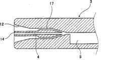
通过保持室4与试剂室5连通的注入口14的前端位于与分析用面板3的本体的一个侧面大致相同的位置,在注入口14的周围,仅上述轴心11侧的面开口,并且形成有从轴心11朝外周方向凹陷的凹部12。另外,凹部12形成为使凹部12的轴心11侧的开口部的截面积成为大于等于凹部12外周侧的开口部的截面积的大小。The front end of theinjection port 14 communicating with thereagent chamber 5 through the holdingchamber 4 is located at approximately the same position as one side surface of the main body of theanalysis panel 3, and around theinjection port 14, only the surface on the side of the above-mentionedaxis 11 is open and formed. There is arecess 12 recessed from theaxis 11 toward the outer circumference. In addition, therecess 12 is formed such that the cross-sectional area of the opening on the side of theaxis 11 of therecess 12 is greater than or equal to the cross-sectional area of the opening on the outer peripheral side of therecess 12 .

另外,注入口14从凹部12的底面突出形成,凹部12的容积构成为可收纳在样品液朝注入口14滴注时附着在注入口附近的样品液滴的大小。Theinjection port 14 protrudes from the bottom surface of therecess 12 , and the volume of therecess 12 is configured to be large enough to accommodate a sample liquid droplet adhering to the vicinity of theinjection port 14 when the sample liquid is dripped into theinjection port 14 .

另外,凹部12的底面与试剂室5连通。具体而言,在凹部12的底面上形成有一端与凹部12连通的一个以上的槽部17,槽部17的另一端(外周方向的端部)与试剂室5连通。In addition, the bottom surface of theconcave portion 12 communicates with thereagent chamber 5 . Specifically, one ormore grooves 17 are formed on the bottom surface of therecess 12 , one end of which communicates with therecess 12 , and the other end (end in the outer peripheral direction) of thegroove 17 communicates with thereagent chamber 5 .

另外,在该实施形态4中,各槽部17的另一端在注入口14的外周侧彼此连通后与试剂室5连通,但也可与试剂室5分别连通。InEmbodiment 4, the other ends of therespective grooves 17 communicate with each other on the outer peripheral side of theinjection port 14 and then communicate with thereagent chamber 5 , but they may communicate with thereagent chambers 5 separately.

由于这样构成,因此,在将样品液滴注到注入口14而供给了样品液的状态下,如图12A所示,在注入口14的附近会附着样品液滴19。将附着有样品液滴19的分析用面板3直接安装到分析用面板保持部件101上,利用绕轴心11旋转而产生的离心力,使附着在注入口14附近的样品液滴如图12B所示地在凹部12内朝箭头20的方向移动、转移至凹部12内的槽部17跟前的位置,最终如图12C所示,使其转移至试剂室5的内部并收集于此。With this configuration, when the sample liquid is dripped into theinjection port 14 and the sample liquid is supplied, as shown in FIG. 12A , the sampleliquid droplet 19 adheres to the vicinity of theinjection port 14 . Theanalysis panel 3 to which thesample droplet 19 is attached is directly installed on the analysispanel holding member 101, and the sample droplet attached near theinjection port 14 is made by using the centrifugal force generated by the rotation around theaxis 11, as shown in FIG. 12B . The ground moves in the direction of thearrow 20 in therecess 12, transfers to the position in front of thegroove 17 in therecess 12, and finally transfers to the inside of thereagent chamber 5 as shown in FIG. 12C and collects there.

即,通过与凹部12连续地设置槽部17,朝凹部12转移来的样品液滴19因离心力而继续朝槽部17的内部转移,在槽部17的内部被毛细管力保持,并进一步被离心力保持在试剂室5的内部,因此,在之后的没有离心力的状态下,也可防止样品液朝外部溢出。That is, by providing thegroove portion 17 continuously with theconcave portion 12, thesample liquid drop 19 transferred to theconcave portion 12 continues to transfer to the inside of thegroove portion 17 due to the centrifugal force, is held by the capillary force inside thegroove portion 17, and is further absorbed by the centrifugal force. Since it is held inside thereagent chamber 5, the sample liquid can be prevented from overflowing to the outside even in a state where there is no centrifugal force thereafter.

像这样,附着在注入口14附近的样品液滴19能直接通过转移样品液时使用的规定离心力的作用而可靠地收集到试剂室5内,因此,可在不存在样品液飞散而被污染的情况下安全地进行样品液中的成分的分析。另外,不会浪费附着在注入口14周围的样品液,可有效地将其用作分析用的样品液。这对于近年来市场上所要求的样品分析中的样品液的少量化而言,在可用同一样品液来补充容量上容易不足的样品液这点上极为有利。In this way, the sampleliquid droplet 19 adhering to the vicinity of theinjection port 14 can be reliably collected into thereagent chamber 5 directly by the predetermined centrifugal force used when transferring the sample liquid, and therefore, it can be prevented from being contaminated by scattering of the sample liquid. The analysis of the components in the sample liquid can be carried out safely under the circumstances. In addition, the sample liquid adhering to the vicinity of theinjection port 14 is not wasted, and can be effectively used as a sample liquid for analysis. This is extremely advantageous in that the same sample liquid can be used to supplement a sample liquid that tends to be insufficient in volume, for reducing the amount of sample liquid in sample analysis that has been demanded in the market in recent years.

另外,通过将槽部17形成在凹部12与试剂室5之间,可在更远离注入口14的位置上将朝凹部12转移来的样品液全部朝槽部17转移。In addition, by forming thegroove portion 17 between therecess portion 12 and thereagent chamber 5 , all the sample liquid transferred to therecess portion 12 can be transferred to thegroove portion 17 at a position farther from theinjection port 14 .

另外,该实施形态4的槽部17的截面形状形成为长方形状,但也可以是圆形、三角形或多边形等其它形状。无论在哪种情况下,为了当分析用面板3在分析结束后从分析用面板保持部件101上拆下而朝重力方向倾斜时槽部17内的样品液也不会掉落,槽部17的轴心11侧的开口部21的厚度d形成为1mm以下。In addition, the cross-sectional shape of thegroove portion 17 in the fourth embodiment is formed in a rectangular shape, but other shapes such as a circle, a triangle, or a polygon may also be used. In any case, when theanalysis panel 3 is detached from the analysispanel holding member 101 after the analysis is completed and tilted in the direction of gravity, the sample liquid in thegroove portion 17 will not drop, thegroove portion 17 The thickness d of the opening 21 on theaxial center 11 side is formed to be 1 mm or less.

另外,与实施形态1时相同,将上述盖子18设置在分析用面板3上,将盖子18打开,朝注入口14滴注样品液,之后,在盖子18被关闭的状态将分析用面板3安装到分析用面板保持部件101上,由此,可进一步提高防止样品液流出的可靠性。即,即使被转移到凹部12的样品液或被转移到室内的样品液受到某种影响而从注入口14和凹部12朝分析用面板3的侧面流出,也会被盖子18挡住,可防止其被释放到外部的事态发生。另外,在分析后,通过在不打开盖子18的情况下直接抛弃,可防止产生污染,适用于一次性的分析用面板。In addition, as inEmbodiment 1, the above-mentionedcover 18 is set on theanalysis panel 3, thecover 18 is opened, and the sample solution is dripped toward theinjection port 14, and then theanalysis panel 3 is attached with thecover 18 closed. On the analysispanel holding member 101, the reliability of preventing the sample liquid from flowing out can be further improved. That is, even if the sample liquid transferred to therecess 12 or the sample liquid transferred to the chamber is affected by some influence and flows out from theinjection port 14 and therecess 12 toward the side of theanalysis panel 3, it will be blocked by thecover 18 to prevent it from flowing out. Events that are released to the outside world. In addition, after the analysis, it is suitable for a disposable analysis panel by directly discarding it without opening thelid 18 to prevent contamination.

(实施形态5)(Embodiment 5)

图13~图15表示了本发明的实施形态5。13 to 15show Embodiment 5 of the present invention.

在上述各实施形态中,分析用面板3朝分析用面板保持部件101的放置状态是,在分析用面板保持部件101的上述轴心11的外周侧配置整个分析用面板3,但在该实施形态5中,如图15所示的,分析用面板3的一部分横切分析用面板保持部件101的上述轴心11而朝相反的一侧突出。In each of the above-mentioned embodiments, theanalysis panel 3 is placed on the analysispanel holding member 101 in such a way that theentire analysis panel 3 is arranged on the outer peripheral side of the above-mentionedaxis 11 of the analysispanel holding member 101, but in thisembodiment 5, as shown in FIG. 15, a part of theanalysis panel 3 protrudes toward the opposite side across theaxis 11 of the analysispanel holding member 101.

如图13所示,在该实施形态中使用的分析用面板3采用了实施形态1~实施形态4中任一个分析用面板3中带有上述盖子18的结构。As shown in FIG. 13, theanalysis panel 3 used in this embodiment has a structure in which the above-mentionedcover 18 is attached to theanalysis panel 3 in any one of the first to fourth embodiments.

图14和图15表示了将具有盖子18的分析用面板3放置到分析用面板保持部件101上之前和之后的形态,分析用面板3在分析用面板保持部件101上的安装位置与实施形态1~实施形态4的安装位置不同。14 and 15 show the configurations before and after placing theanalysis panel 3 with thecover 18 on the analysispanel holding member 101, and the installation position of theanalysis panel 3 on the analysispanel holding member 101 is the same as inEmbodiment 1. -The mounting position ofEmbodiment 4 is different.

具体而言,在实施形态1~实施形态4中,分析用面板3安装在分析用面板保持部件101的轴心11的外周侧,但在该实施形态5中,分析用面板3的注入口14以横切分析用面板保持部件101的轴心11的形态安装。另外,根据需要,如图15所示,在上述盖子18的内侧,在盖子18被关闭的状态下与注入口14相对的位置上空开空隙24地配置吸收部件22。Specifically, inEmbodiments 1 to 4, theanalysis panel 3 is mounted on the outer peripheral side of theaxis 11 of the analysispanel holding member 101, but in thisEmbodiment 5, theinlet 14 of theanalysis panel 3 It is mounted so as to cut across theaxis 11 of thepanel holding member 101 for analysis. In addition, as needed, as shown in FIG. 15 , an absorbingmember 22 is disposed inside thelid 18 at a position facing theinjection port 14 with thelid 18 closed, leaving a gap 24 there.

由于这样构成,因此,在将从注入口14注入了规定量的样品液并将盖子18关闭后的分析用面板3安装到分析用面板保持部件101上、驱动电动机102旋转时,与上述实施形态一样,位于保持室4内的样品液会从轴心11向试剂室5侧朝箭头25方向移动。另一方面,附着在注入口14附近的样品液滴19会因离心力而朝箭头26的方向移动,被盖子18捕获。在上述吸收部件22设置在盖子18的内侧时,样品液滴被转移至吸收部件22,最终被吸收部件22吸引。即,附着在注入口14附近的样品液滴19通过关闭盖子18而在盖子内被切断,可防止其朝外部放出,在分析后也无需使盖子打开,不会产生污染,适用于可直接废弃的一次性分析用面板。Due to such a configuration, when theanalysis panel 3 after injecting a predetermined amount of sample solution from theinjection port 14 and closing thecover 18 is attached to the analysispanel holding member 101 and the driving motor 102 is rotated, it is the same as that of the above-mentioned embodiment. Similarly, the sample liquid in the holdingchamber 4 will move from theaxis 11 to thereagent chamber 5 in the direction of the arrow 25 . On the other hand, sampleliquid droplets 19 adhering to the vicinity of theinjection port 14 move in the direction of thearrow 26 due to centrifugal force and are captured by thecap 18 . When the above-mentioned absorbingmember 22 is provided inside thecover 18 , the sample liquid droplets are transferred to the absorbingmember 22 and finally attracted by the absorbingmember 22 . That is, thesample liquid droplets 19 adhering to the vicinity of theinjection port 14 are cut off in the cover by closing thecover 18, which prevents them from being released to the outside, and there is no need to open the cover after analysis, so that no pollution occurs, and it is suitable for direct disposal. single-use analysis panels.

吸收部件22可使用由例如聚丙烯或纸材料构成的无纺布等。该吸收部件22的大小只要是能收纳附着在上述注入口14附近的样品液的大小即可。As theabsorbent member 22, a nonwoven fabric or the like made of, for example, polypropylene or paper material can be used. The absorbingmember 22 may have a size that can accommodate the sample liquid adhering to the vicinity of theinjection port 14 .

像这样,通过直接利用使位于分析用面板3的保持室4内的样品液朝试剂室5之后转移时使用的离心力的作用,能将附着在注入口14附近的样品液滴19可靠地收集到盖子18的内部。In this way, by directly using the centrifugal force used when the sample liquid in the holdingchamber 4 of theanalysis panel 3 is transferred to thereagent chamber 5, the sampleliquid droplet 19 adhering to the vicinity of theinjection port 14 can be reliably collected. The inside of thecover 18.

(实施形态6)(Embodiment 6)

图16~图19A、图19B、图19C表示了本发明的实施形态6。16 to 19A, 19B, and19C show Embodiment 6 of the present invention.

在具有盖子18的分析用面板3被安装到分析用面板保持部件101上时轴心11与分析用面板3的位置关系与实施形态4相同,但在该实施形态6中,在盖子18的内侧设置有凹部23。When theanalytical panel 3 having thecover 18 is attached to the analyticalpanel holding member 101, the positional relationship between theaxis 11 and theanalytical panel 3 is the same as that ofEmbodiment 4, but in thisEmbodiment 6, inside the cover 18A recess 23 is provided.

如图17和图18所示,理想的是,在盖子18被关闭的状态下,分析用面板3的注入口14设定在从盖子18的底部离开距离27的位置上,注入口14不与盖子18的底部接触。从盖子18的底部朝注入口14侧突出并与注入口14的外侧空开距离地将其包围的凹部23的突出量28被设定成使注入口14的前端从凹部23的开口进入内侧。As shown in FIGS. 17 and 18 , ideally, when thecover 18 is closed, theinjection port 14 of theanalysis panel 3 is set at adistance 27 from the bottom of thecover 18, and theinjection port 14 is not separated from the bottom of thecover 18. The bottom of thecover 18 touches. Theprojection amount 28 of therecess 23 protruding from the bottom of thecover 18 toward the fillingport 14 and surrounding the fillingport 14 at a distance is set so that the tip of the fillingport 14 enters the inside from the opening of therecess 23 .

由于这样构成,因此,在将从注入口14注入了规定量的样品液并将盖子18关闭后的分析用面板3安装到分析用面板保持部件101上、驱动电动机102旋转时,与上述实施形态一样,位于保持室4内的样品液会从轴心11向试剂室5侧朝箭头25方向移动。另一方面,附着在注入口14附近的样品液滴19会因离心力而朝箭头26的方向移动,被盖子18的凹部23捕获。即,附着在注入口14附近的样品液滴19通过关闭盖子18而在盖子内被切断,可防止其朝外部放出,在分析后也无需使盖子打开,不会产生污染,适用于可直接废弃的一次性分析用面板。Due to such a configuration, when theanalysis panel 3 after injecting a predetermined amount of sample solution from theinjection port 14 and closing thecover 18 is attached to the analysispanel holding member 101 and the driving motor 102 is rotated, it is the same as that of the above-mentioned embodiment. Similarly, the sample liquid in the holdingchamber 4 will move from theaxis 11 to thereagent chamber 5 in the direction of the arrow 25 . On the other hand, the sampleliquid droplet 19 adhering to the vicinity of theinjection port 14 moves in the direction of thearrow 26 due to the centrifugal force, and is captured by theconcave portion 23 of thecap 18 . That is, thesample liquid droplets 19 adhering to the vicinity of theinjection port 14 are cut off in the cover by closing thecover 18, which prevents them from being released to the outside, and there is no need to open the cover after analysis, so that no pollution occurs, and it is suitable for direct disposal. single-use analysis panels.

另外,在分析用面板3中注入了规定量的样品液后将其安装到分析用面板保持部件101上、进行样品液滴的转移时所需的转速一般需要是1000rpm以上,但在用表面活化剂等对凹部23的整个内周面、估计会附着样品液滴19的注入口14附近进行了亲水性处理时,只需使由几百rpm的旋转而形成的离心力起作用,就可使样品液滴朝凹部23的底部转移并进行收集。In addition, after injecting a predetermined amount of sample liquid into theanalysis panel 3 and attaching it to the analysispanel holding member 101 to transfer the sample liquid droplet, the rotational speed generally needs to be 1000 rpm or more. When the entire inner peripheral surface of theconcave portion 23 and the vicinity of theinjection port 14 where thesample droplet 19 is expected to be adhered are subjected to a hydrophilic treatment, the centrifugal force generated by the rotation of several hundreds of rpm can be applied. The sample droplets are transferred toward the bottom of therecess 23 and collected.

另外,如图18中的双点划线所示,当根据需要在凹部23内设置了吸收部件22时,附着在注入口14附近的样品液滴19最终会被吸收部件22吸引,因此,即使凹部23的开口朝重力起作用的下侧倾斜,也可防止样品液朝吸收部件22外漏出、或朝注入口14转移并再次附着。In addition, as shown by the two-dot chain line in FIG. 18, when the absorbingmember 22 is provided in theconcave portion 23 as necessary, the sampleliquid droplet 19 adhering to the vicinity of theinjection port 14 will eventually be attracted by the absorbingmember 22. Therefore, even The opening of theconcave portion 23 is inclined toward the lower side where gravity acts, so that the sample liquid can also be prevented from leaking out of theabsorbent member 22 or being transferred to theinjection port 14 and attached again.

另外,也可在盖子18内设置与实施形态1一样的凹部12的构造。In addition, the structure of the recessedpart 12 similar toEmbodiment 1 may be provided in thecover 18. As shown in FIG.

另外,也可与上述凹部23连续地在盖子18内形成利用毛细管力来保持样品液的槽。具体而言,可采用如图19A、图19B、图19C所示的结构。图19A是上述实施形态的分析用面板3被安装在分析装置的分析用面板保持部件101上时注入口的周边结构的剖视图。图19B是从注入口14的方向看盖子18的内侧的主视图。图19C是沿图19B的B-BB线的剖视图,是图19A的状态的水平剖视图。像这样,在凹部23的底部设置有许多间壁29。相邻间壁29相互之间的间隔被设定成能以毛细管力来吸取飞来的样品液滴19并将其保持的间隔,通过分析用面板保持部件101的旋转,附着在注入口14周边的样品液滴19朝间壁29飞来而被保持在间壁29相互之间。In addition, a groove for holding the sample liquid by capillary force may be formed in thecover 18 continuously with the above-mentionedconcave portion 23 . Specifically, the structures shown in Fig. 19A, Fig. 19B, and Fig. 19C can be adopted. Fig. 19A is a cross-sectional view of the surrounding structure of the injection port when theanalysis panel 3 of the above embodiment is mounted on the analysispanel holding member 101 of the analysis device. FIG. 19B is a front view of the inside of thecap 18 viewed from the direction of theinjection port 14 . FIG. 19C is a cross-sectional view along line B-BB in FIG. 19B , and is a horizontal cross-sectional view of the state shown in FIG. 19A . In this way,many partition walls 29 are provided at the bottom of theconcave portion 23 . The distance betweenadjacent partition walls 29 is set so that the flying sampleliquid droplet 19 can be sucked and held by capillary force. Thesample liquid droplets 19 fly toward thepartition walls 29 and are held between thepartition walls 29 .

工业上的可利用性Industrial availability

采用本发明,样品液与分析试剂在反应后的测定也可在分析用面板上迅速地进行,特别是在样品液的注入时,操作极为容易且防止污染方面的安全性也极高,因此,本发明适用作血液等的分析装置。According to the present invention, the measurement of the sample liquid and the analysis reagent after the reaction can also be carried out quickly on the analysis panel, especially when the sample liquid is injected, the operation is extremely easy and the safety in terms of pollution prevention is also extremely high. Therefore, The present invention is suitable as an analysis device for blood and the like.

Claims (20)

Translated fromChinese
1.一种分析用面板,在面板本体的一个侧面上设置有样品液的注入口,在所述面板本体的内部设置有与所述注入口连通的室,滴注于所述注入口的样品液朝该室转移,在将所述注入口配置在旋转轴心侧的状态下使所述面板本体旋转,在所述室内进行所述样品液中的成分的分析,其特征在于,1. A panel for analysis, one side of the panel body is provided with an injection port for sample liquid, and a chamber communicating with the injection port is provided inside the panel body, and the sample dripped into the injection port The liquid is transferred to the chamber, and the panel body is rotated with the injection port arranged on the side of the rotation axis, and the components in the sample liquid are analyzed in the chamber, and it is characterized in that,所述注入口呈从面板本体的所述一个侧面朝远离室的方向突出的形状,在面板本体的所述一个侧面前面的所述注入口周围形成有凹部。The injection port has a shape protruding from the one side surface of the panel body in a direction away from the chamber, and a recess is formed around the injection port in front of the one side surface of the panel body.2.如权利要求1所述的分析用面板,其特征在于,所述注入口的前端面位于与面板本体的一侧面大致相同的平面上。2. The analysis panel according to claim 1, wherein the front end surface of the inlet is located on substantially the same plane as one side surface of the panel body.3.如权利要求1所述的分析用面板,其特征在于,所述凹部的开口部的截面积的大小大于等于凹部内端部的截面积。3 . The analysis panel according to claim 1 , wherein the cross-sectional area of the opening of the recess is greater than or equal to the cross-sectional area of the inner end of the recess. 4 .4.如权利要求1所述的分析用面板,其特征在于,所述注入口以所述凹部的底面为基端突出形成。4 . The analysis panel according to claim 1 , wherein the injection port protrudes from the bottom surface of the concave portion as a base end.5.如权利要求1所述的分析用面板,其特征在于,所述凹部的容积是可收纳在样品液朝所述注入口滴注时附着在所述注入口附近的样品液的大小。5 . The analysis panel according to claim 1 , wherein the volume of the concave portion is large enough to accommodate the sample liquid adhering to the vicinity of the injection port when the sample liquid is dripped toward the injection port. 5 .6.如权利要求1所述的分析用面板,其特征在于,在所述凹部内配置有吸收所述样品液的吸收部件。6. The analysis panel according to claim 1, wherein an absorbing member for absorbing the sample liquid is arranged in the concave portion.7.如权利要求6所述的分析用面板,其特征在于,所述吸收部件配置在与因绕所述轴心旋转产生的离心力而转移到凹部内的样品液接触的位置上。7. The analysis panel according to claim 6, wherein the absorbing member is disposed at a position where it contacts the sample liquid transferred into the recess due to centrifugal force generated by rotation about the axis.8.如权利要求1所述的分析用面板,其特征在于,与所述凹部连通地形成利用毛细管力来保持样品液的槽部。8. The analysis panel according to claim 1, wherein a groove portion for holding the sample liquid by capillary force is formed in communication with the concave portion.9.如权利要求8所述的分析用面板,其特征在于,所述槽部与所述凹部的底部连通。9. The analysis panel according to claim 8, wherein the groove communicates with the bottom of the recess.10.如权利要求8所述的分析用面板,其特征在于,所述槽部呈下述形状:使因绕所述轴心旋转产生的离心力而转移到凹部内的样品液在所述离心力的作用下继续朝内部转移。10. The panel for analysis according to claim 8, wherein the groove portion has a shape that allows the sample liquid transferred into the concave portion due to the centrifugal force generated by the rotation around the axis to be within the range of the centrifugal force. Under the action, it continues to move towards the inside.11.如权利要求1所述的分析用面板,其特征在于,所述凹部与所述室连通。11. The analysis panel according to claim 1, wherein the recess communicates with the chamber.12.如权利要求11所述的分析用面板,其特征在于,连通所述凹部与所述室的通路构成为:使附着在注入口附近的样品液在绕所述轴心旋转产生的离心力的作用下朝所述室内转移。12. The panel for analysis according to claim 11, wherein the passage connecting the recessed portion and the chamber is configured such that the sample liquid adhering to the vicinity of the injection port rotates around the axis of the centrifugal force generated. Under the action, it is transferred to the said chamber.13.如权利要求1所述的分析用面板,其特征在于,在与所述注入口连通的所述室内具有在作为样品液的血液的分析中使用的分析试剂。13. The analysis panel according to claim 1, wherein an analysis reagent used for analysis of blood as a sample liquid is provided in the chamber communicating with the injection port.14.如权利要求1所述的分析用面板,其特征在于,具有覆盖所述注入口和所述凹部的可开闭的盖子。14. The analysis panel according to claim 1, further comprising an openable and closable cover covering the inlet and the recess.15.如权利要求1所述的分析用面板,其特征在于,15. The panel for analysis according to claim 1, wherein具有覆盖所述注入口和所述凹部的可开闭的盖子,having an openable and closable cover covering the injection port and the recess,在所述盖子的内侧设置有吸收样品液的吸收部件。An absorbent member for absorbing a sample liquid is provided inside the cover.16.如权利要求1所述的分析用面板,其特征在于,16. The panel for analysis according to claim 1, wherein具有覆盖所述注入口和所述凹部的可开闭的盖子,having an openable and closable cover covering the injection port and the recess,在所述盖子的内侧设置有吸收样品液的吸收部件,An absorbent member for absorbing the sample liquid is provided on the inner side of the cover,在所述注入口与所述吸收部件之间形成有空隙。A gap is formed between the inlet and the absorbent member.17.如权利要求1所述的分析用面板,其特征在于,17. The panel for analysis according to claim 1, wherein所述室包括:The chamber includes:临时保持被滴注于所述注入口的样品液的保持室;a holding chamber for temporarily holding the sample liquid dripped into the injection port;保持分析所需的分析试剂的试剂室;以及a reagent compartment for holding analytical reagents required for the analysis; and测定室区域,被所述保持室保持的样品液和所述分析试剂朝该测定室区域转移,使两者混合,并进行与分析试剂混合后的样品液的测定。In the measurement chamber area, the sample liquid held in the holding chamber and the analysis reagent are transferred to the measurement chamber area to be mixed, and the sample liquid mixed with the analysis reagent is measured.18.如权利要求14所述的分析用面板,其特征在于,在所述注入口的周缘部的表面、所述凹部、连通所述凹部与所述室的通路、所述盖子部件的内表面中的至少一个上涂布了表面活化剂。18. The analysis panel according to claim 14, wherein on the surface of the peripheral portion of the injection port, the recess, the passage connecting the recess and the chamber, and the inner surface of the cover member At least one of them is coated with a surfactant.19.一种分析装置,包括:19. An analytical device comprising:权利要求1至8中任一项所述的分析用面板、以及The panel for analysis according to any one of claims 1 to 8, and供所述分析用面板进行安装的分析用面板保持部件,an analysis panel holding part for mounting the analysis panel,在使所述分析用面板保持部件旋转而产生的离心力的作用下使滴注于所述注入口的样品液朝室转移,通过以光学方式接触所述室内的样品液,检测出信号,进行分析处理,The sample liquid dripped into the injection port is transferred to the chamber by the centrifugal force generated by rotating the analysis panel holding member, and the sample liquid in the chamber is optically contacted to detect a signal and perform analysis. deal with,其特征在于,It is characterized in that,将所述分析用面板以所述注入口位于所述分析用面板保持部件的旋转轴心的外周侧、或所述注入口横切所述分析用面板保持部件的旋转轴心的形态安装在所述分析用面板保持部件上进行分析动作。The analysis panel is attached in such a manner that the injection port is located on the outer peripheral side of the rotation axis of the analysis panel holding member, or the injection port crosses the rotation axis of the analysis panel holding member. The analysis operation is performed on the analysis panel holding part described above.20.一种分析用面板,在面板本体的一个侧面上设置有样品液的注入口,在所述面板本体的内部设置有与所述注入口连通的室,被滴注于所述注入口的样品液朝该室转移,通过使所述面板本体绕轴心旋转,在所述室内进行所述样品液中的成分的分析,其特征在于,20. A panel for analysis, wherein an injection port for a sample liquid is provided on one side of the panel body, and a chamber communicating with the injection port is provided inside the panel body, and is dripped into the injection port. The sample liquid is transferred to the chamber, and the components in the sample liquid are analyzed in the chamber by rotating the panel body around the axis, and it is characterized in that,所述注入口呈从面板本体的所述一个侧面朝着远离室的方向突出的形状,The injection port is in a shape protruding from the one side of the panel body toward a direction away from the chamber,在所述面板本体上设置有覆盖所述注入口的可开闭的盖子,An openable and closable cover covering the injection port is provided on the panel body,在所述盖子的内侧设置有对附着在所述注入口附近的样品液滴进行捕捉的凹部或吸收所述样品液滴的吸收部件,A concave portion for catching sample liquid droplets adhering to the vicinity of the injection port or an absorbing member for absorbing the sample liquid droplets is provided on the inner side of the cover,在所述盖子被关闭的状态下,在所述注入口与所述凹部之间、或所述注入口与所述吸收部件之间形成有空隙。In a state where the lid is closed, a gap is formed between the injection port and the recess, or between the injection port and the absorbent member.
CN2007800246334A2006-06-302007-06-27 Analysis panel and analysis device using sameActiveCN101479609B (en)

Applications Claiming Priority (3)

Application NumberPriority DateFiling DateTitle
JP20061806692006-06-30
JP180669/20062006-06-30
PCT/JP2007/062858WO2008001796A1 (en)2006-06-302007-06-27Panel for analysis and analyzer using the same

Publications (2)

Publication NumberPublication Date
CN101479609A CN101479609A (en)2009-07-08
CN101479609Btrue CN101479609B (en)2012-09-05

Family

ID=38845560

Family Applications (1)

Application NumberTitlePriority DateFiling Date
CN2007800246334AActiveCN101479609B (en)2006-06-302007-06-27 Analysis panel and analysis device using same

Country Status (4)

CountryLink
US (1)US8158079B2 (en)
EP (1)EP2037280B1 (en)
CN (1)CN101479609B (en)
WO (1)WO2008001796A1 (en)

Families Citing this family (10)

* Cited by examiner, † Cited by third party
Publication numberPriority datePublication dateAssigneeTitle
US8667833B2 (en)2007-10-292014-03-11Panasonic CorporationAnalysis device, and analysis apparatus and method using the same
EP3521833B1 (en)2007-10-302021-05-26PHC Holdings CorporationAnalyzing device
JP5274086B2 (en)*2008-04-102013-08-28パナソニック株式会社 Analytical device and sample liquid analysis method using the same
CN101883985B (en)*2008-02-052013-11-20松下电器产业株式会社 Analytical instrument, analytical device and analytical method using the analytical instrument
DE102009043226B4 (en)2009-09-282012-09-27Siemens Aktiengesellschaft Flat body in the manner of a chip card for biochemical analysis and method for its use
CN103217517B (en)*2012-01-202014-07-23光宝科技股份有限公司 Rotary device and blood analysis equipment
CN102707044B (en)*2012-05-312014-08-27辽宁国际旅行卫生保健中心Vertical western blot antibody incubation box
EP2942104A1 (en)2014-05-082015-11-11Radisens Diagnostics Ltd.Sample applicator for point of care device
CN106501499B (en)2015-09-072019-12-17埃克西亚斯医药有限公司Movable measuring unit
JP1679678S (en)*2020-07-022021-02-22

Citations (2)

* Cited by examiner, † Cited by third party
Publication numberPriority datePublication dateAssigneeTitle
JP2004239743A (en)*2003-02-062004-08-26Matsushita Electric Ind Co Ltd Liquid sample analysis disc
CN1620610A (en)*2002-01-252005-05-25松下电器产业株式会社 Disc for sample analysis and sample analysis device

Family Cites Families (12)

* Cited by examiner, † Cited by third party
Publication numberPriority datePublication dateAssigneeTitle
JPS60154160A (en)1984-01-231985-08-13Hitachi Koki Co Ltd Dispensing and measuring mechanism for centrifuged samples
US4883763A (en)*1984-05-031989-11-28Abbott LaboratoriesSample processor card for centrifuge
SE465742B (en)1989-04-261991-10-21Migrata Uk Ltd KYVETT BEFORE RECORDING FOR AT LEAST ONE FLUID
JP3213566B2 (en)*1996-04-262001-10-02アークレイ株式会社 Sample analysis tool, sample analysis method and sample analyzer using the same
US8231845B2 (en)*2000-10-252012-07-31Steag MicropartsStructures for uniform capillary flow
DE50110742D1 (en)2000-10-252006-09-28Boehringer Ingelheim Micropart Microstructured platform for studying a liquid
JP3788338B2 (en)2001-12-132006-06-21松下電器産業株式会社 Analysis disc
CN100382870C (en)2001-12-282008-04-23株式会社日立高新技术 Extraction device, chemical analysis device and chemical analysis method
US7604775B2 (en)2002-08-122009-10-20Bayer Healthcare LlcFluid collecting and monitoring device
ATE385572T1 (en)*2004-03-052008-02-15Egomedical Swiss Ag ANALYTE TEST SYSTEM FOR DETERMINING THE CONCENTRATION OF AN ANALYTE IN A PHYSIOLOGICAL LIQUID
JP4478776B2 (en)2004-08-092010-06-09独立行政法人物質・材料研究機構 Blood analyzer and blood analysis method
JP2006158335A (en)2004-12-092006-06-22Olympus CorpDividedly injecting device and culture treatment apparatus

Patent Citations (2)

* Cited by examiner, † Cited by third party
Publication numberPriority datePublication dateAssigneeTitle
CN1620610A (en)*2002-01-252005-05-25松下电器产业株式会社 Disc for sample analysis and sample analysis device
JP2004239743A (en)*2003-02-062004-08-26Matsushita Electric Ind Co Ltd Liquid sample analysis disc

Also Published As

Publication numberPublication date
EP2037280B1 (en)2020-06-24
CN101479609A (en)2009-07-08
US8158079B2 (en)2012-04-17
EP2037280A4 (en)2017-08-02
EP2037280A1 (en)2009-03-18
WO2008001796A1 (en)2008-01-03
US20090205447A1 (en)2009-08-20

Similar Documents

PublicationPublication DateTitle
CN101479609B (en) Analysis panel and analysis device using same
JP4859769B2 (en) Analysis panel and analyzer using the same
US10933413B2 (en)Analyzing device having spot application section with inclined face
CN102721822B (en)Instrument drive device for analysis
JP4614992B2 (en) Analytical device, analytical apparatus and analytical method using the same
JP5376429B2 (en) Analytical device, analytical apparatus and analytical method using the same
CN111602058A (en)Substrate for sample analysis, sample analyzer, sample analysis system, and method for controlling sample analyzer
JP5273990B2 (en) Analytical device, analytical apparatus and analytical method using the same
JP5274086B2 (en) Analytical device and sample liquid analysis method using the same
JP2009115670A (en) Analytical device, analytical apparatus and analytical method using the same
JP4859804B2 (en) Analytical device, analytical apparatus and analytical method using the same
JP2010151556A (en)Analyzer

Legal Events

DateCodeTitleDescription
C06Publication
PB01Publication
C10Entry into substantive examination
SE01Entry into force of request for substantive examination
C14Grant of patent or utility model
GR01Patent grant
ASSSuccession or assignment of patent right

Owner name:PANASONIC HEALTHCARE + MEDICAL EQUIPMENT CO., LTD.

Free format text:FORMER OWNER: MATSUSHITA ELECTRIC INDUSTRIAL CO, LTD.

Effective date:20140529

C41Transfer of patent application or patent right or utility model
TR01Transfer of patent right

Effective date of registration:20140529

Address after:Ehime Prefecture, Japan

Patentee after:Panasonic Healthcare Co., Ltd

Address before:Osaka Japan

Patentee before:Matsushita Electric Industrial Co., Ltd.

ASSSuccession or assignment of patent right

Owner name:PANASONIC HEALTHCARE HOLDINGS CO., LTD.

Free format text:FORMER OWNER: PANASONIC HEALTHCARE + MEDICAL EQUIPMENT CO., LTD.

Effective date:20150402

TR01Transfer of patent right

Effective date of registration:20150402

Address after:Tokyo, Japan

Patentee after:Panasonic's health medical treatment is controlled interest Co., Ltd.

Address before:Ehime Prefecture, Japan

Patentee before:Panasonic Healthcare Co., Ltd

CP01Change in the name or title of a patent holder

Address after:Tokyo, Japan

Patentee after:Pu Hei holding company

Address before:Tokyo, Japan

Patentee before:Panasonic's health medical treatment is controlled interest Co., Ltd.

CP01Change in the name or title of a patent holder

[8]ページ先頭

©2009-2025 Movatter.jp