CN101479596A - Glazing inspection method - Google Patents
Glazing inspection methodDownload PDFInfo
- Publication number
- CN101479596A CN101479596ACNA2007800238677ACN200780023867ACN101479596ACN 101479596 ACN101479596 ACN 101479596ACN A2007800238677 ACNA2007800238677 ACN A2007800238677ACN 200780023867 ACN200780023867 ACN 200780023867ACN 101479596 ACN101479596 ACN 101479596A
- Authority
- CN
- China
- Prior art keywords
- glazing
- image
- light source
- angle
- subset
- Prior art date
- Legal status (The legal status is an assumption and is not a legal conclusion. Google has not performed a legal analysis and makes no representation as to the accuracy of the status listed.)
- Pending
Links
Images


Classifications
- G—PHYSICS
- G01—MEASURING; TESTING
- G01N—INVESTIGATING OR ANALYSING MATERIALS BY DETERMINING THEIR CHEMICAL OR PHYSICAL PROPERTIES
- G01N21/00—Investigating or analysing materials by the use of optical means, i.e. using sub-millimetre waves, infrared, visible or ultraviolet light
- G01N21/84—Systems specially adapted for particular applications
- G01N21/88—Investigating the presence of flaws or contamination
- G01N21/95—Investigating the presence of flaws or contamination characterised by the material or shape of the object to be examined
- G01N21/958—Inspecting transparent materials or objects, e.g. windscreens
- G01N2021/9586—Windscreens
Landscapes
- Physics & Mathematics (AREA)
- Health & Medical Sciences (AREA)
- Life Sciences & Earth Sciences (AREA)
- Chemical & Material Sciences (AREA)
- Analytical Chemistry (AREA)
- Biochemistry (AREA)
- General Health & Medical Sciences (AREA)
- General Physics & Mathematics (AREA)
- Immunology (AREA)
- Pathology (AREA)
- Length Measuring Devices By Optical Means (AREA)
- Investigating Materials By The Use Of Optical Means Adapted For Particular Applications (AREA)
Abstract
Description
Translated fromChinese技术领域technical field
本发明涉及玻璃窗检验(glazing inspection)的方法,特别是用于汽车玻璃窗的检验的方法。The present invention relates to a method of glazing inspection, in particular for the inspection of automotive glazing.
背景技术Background technique
在生产期间,对用于汽车玻璃窗的玻璃进行各种缺陷的检验,这些缺陷可能会影响成品玻璃窗产品的光学质量。例如,这些玻璃可能包含杂质或瑕疵,例如硫化镍杂质或气泡。或者,这些玻璃可以具有在处理中造成的瑕疵,例如,用于将玻璃切割成合适大小的切割和研磨处理造成的边缘瑕疵、发亮物(brillantatura)和毛刺(shiner),以及用于使玻璃成形的煅烧和弯曲处理造成的变形、厚度和曲率变化。During production, glass for automotive glazing is inspected for various defects that may affect the optical quality of the finished glazing product. For example, these glasses may contain impurities or blemishes, such as nickel sulfide inclusions or air bubbles. Alternatively, the glasses may have processing imperfections such as edge imperfections, brillantatura and shiners from the cutting and grinding processes used to cut the glass to size, and to make the glass Distortion, thickness and curvature changes due to calcining and bending processes for forming.
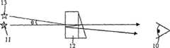
用于制造挡风玻璃和后窗玻璃(blacklight)的玻璃的一个特定问题是,当通过该玻璃查看对象时,在其中看到双重图像或二次图像。该影响是由于玻璃内的厚度变化造成的,以不同的程度呈现,并且由于屏幕的形状和在制造过程中引入的可能的成形误差而造成。图1是二次图像怎样通过光楔出现的示意图。观察者10通过挡风玻璃12观察远处的对象11。在观察者10通过其进行观看的区域上,挡风玻璃12的厚度改变。该屏幕有效地用作当光穿过玻璃时折射光的局部光楔(localised wedge)。在内侧玻璃/空气界面处,一些光向外侧玻璃/空气界面反射,一些光及时地从该外侧玻璃/空气界面向驾驶员反射回去,这样驾驶员观察到从主图像偏离角θ的更加暗的二次图像。角度θ表示二次图像相对于对象的主图像的偏离,并且取决于在观察点处玻璃中的光楔和弯曲的量。A particular problem with the glass used to make windshields and blacklights is seeing double or secondary images in objects when viewed through the glass. This effect is due to thickness variations within the glass, present to varying degrees, and due to the shape of the screen and possible forming errors introduced during the manufacturing process. Figure 1 is a schematic diagram of how a secondary image emerges through an optical wedge. An
过多层次的二次图像会令挡风玻璃被安装在其中的车辆的驾驶员不安,并且也引起对安全问题。在ECE R43标准下,在挡风玻璃内允许的二次图像的量根据主图像和二次图像之间的偏离角(divergence angle)θ来衡量。目前最大的能接受的偏离角是15弧分。Too many layers of secondary images can be disturbing to the driver of the vehicle in which the windshield is installed, and also cause safety concerns. Under the ECE R43 standard, the amount of secondary images allowed in the windshield is measured in terms of the divergence angle θ between the primary image and the secondary image. Currently the maximum acceptable deflection angle is 15 arc minutes.
无论玻璃窗是否通过ECE R43,二次图像标准可以以两种方式来评估,即使用背光照明的“环和点(ring-and-dot)”目标或准直仪-望远镜排列。Regardless of whether the glazing passes ECE R43, secondary image criteria can be assessed in two ways, using a backlit "ring-and-dot" target or a collimator-telescope arrangement.
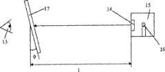
“环和点”目标测试在图2a和图2b中示意性地示出。如图2a所示,该测试涉及观察者13通过玻璃窗测试样本17观察置于发光盒15(包含适当的光源16,例如钨丝灯泡)上的“环和点”目标。玻璃窗17放置在离发光盒15大于7m的距离1处,以倾角
D=l.tan(15′)D=l.tan(15')
如果出现的中心点的二次图像触及外侧环的主图像或者位于外侧环的主图像的外面,那么该玻璃窗测试不合格。If the secondary image of the center point occurs touching or outside the primary image of the outer ring, the glazing test fails.
这种测试有缺点。首先,只是对二次图像的定性测量。尽管可以测试玻璃窗的不同区域,但是很难想象二次图像在整个玻璃窗上怎样改变或者很难创建二次图像变化的概貌(profile)。只能产生示出通过或未通过测试的区域的概貌。其次,不同观察者观察到的二次图像的可察觉量不同使得很难保证测试的可靠性。This test has drawbacks. First, just a qualitative measure of the secondary image. Although it is possible to test different areas of the glazing, it is difficult to visualize how the secondary image changes across the glazing or to create a profile of the secondary image changes. Only an overview can be generated showing the areas that passed or failed the test. Second, differences in the perceived amount of secondary images observed by different observers make it difficult to guarantee the reliability of the test.
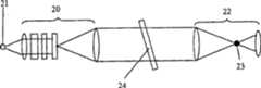
图3a和图3b示意性地示出准直仪-望远镜测试的设置(set-up)。由于这种测试提供对二次图像的定量测量,因此这种测试与“环和点”目标测试相比是有利的。Figures 3a and 3b schematically illustrate the collimator-telescope test set-up. This test compares favorably to the "ring and dot" target test because it provides a quantitative measure of the secondary image.
图3a是用于准直测试的设置的示意性横截面。准直器20在无限远处形成中心(从点光源21开始)具有亮点的极坐标系统的图像。在观察望远镜22中,直径比被投射的亮点大一点的小的不透明点23位于在焦平面处的光轴上。玻璃片24被置于准直望远镜20和观察望远镜22之间。如果玻璃片24显示二次图像,将使用观察望远镜来探测并使用极坐标系统来定量。Figure 3a is a schematic cross-section of the setup used for the alignment test. The
图3b示出用来确定主图像和二次图像之间的角度的极坐标系统。观察望远镜22中的目标或者准直望远镜20中的光栅可以用坐标来标出。主轴25以30°的间隔围绕圆标注(mark)。每个轴都从圆心以弧分放射状地标注。为了清晰起见,这些标记没有示出。如果玻璃片24表现出二次图像,那么在距离极坐标系统的中心一定距离处出现虚点27。这个虚点27是光源21的二次图像。暗点28表示视场的中心,并且是由于在观察望远镜中的不透明点23造成的。不透明点的目的是为了阻挡亮的主图像,要不然主图像将干扰暗的二次光点的位置。于是偏离角(这两个图像之间的分开的程度)直接从极坐标刻度以弧分被读取。Figure 3b shows the polar coordinate system used to determine the angle between the primary and secondary images. An object in the
但是,这种方法也有缺点。尽管给出了对玻璃的变形程度的定量评估,对于被检测的单独的玻璃片该系统需要仔细地对齐并手工放置。此外,操作者需要了解二次图像的位置以便确定偏离角。为了生成表示在整个玻璃片上的二次图像角的概貌,在玻璃的整个表面上必须手工进行数百次的测量。这是费时和不切实际的。而且,由于其强度低,二次光点(secondary spot)可能很难看到。However, this approach also has disadvantages. While giving a quantitative assessment of the degree of deformation of the glass, the system requires careful alignment and manual placement of the individual pieces of glass to be inspected. Furthermore, the operator needs to know the location of the secondary image in order to determine the angle of deviation. In order to generate an overview representing the secondary image angles across the glass slide, hundreds of measurements must be made manually over the entire surface of the glass. This is time consuming and impractical. Also, secondary spots can be difficult to see due to their low intensity.
发明内容Contents of the invention
在第一方面,本发明旨在通过提供确定在由玻璃窗生成的主图像和二次图像之间的偏离角的方法来解决这些问题,该方法包括:使用光源照射该玻璃窗;使用图像捕获装置捕获由玻璃窗生成的光源的主图像和二次图像;确定主图像和二次图像之间的距离;以及使用这个距离计算主图像和二次图像之间的偏离角。In a first aspect, the present invention aims to solve these problems by providing a method of determining the angle of deviation between a primary image and a secondary image generated by a glazing, the method comprising: illuminating the glazing with a light source; using image capture The apparatus captures a primary image and a secondary image of a light source generated by the glazing; determines a distance between the primary image and the secondary image; and uses this distance to calculate an offset angle between the primary image and the secondary image.
通过使用图像捕获装置,从而使用检测过程的自动化部分,可以去除与使用各观察者对特定玻璃窗的定量的偏离角进行测量相关的不确定性。By using an image capture device, and thus using an automated part of the inspection process, the uncertainty associated with measuring the quantitative deflection angle of a particular glazing with individual observers can be removed.
该玻璃窗可以用透射光照射。优选地,图像捕获装置是CMOS(复合金属氧化物半导体)照相机。或者,图像捕获装置是CCD(电荷耦合装置)照相机。该点光源优选是LED(发光二极管)阵列。该阵列可以包含至少两个LED。优选地,该阵列包含三个LED。优选地,对于阵列中的每个LED,生成主图像和二次图像。该阵列中的LED可以沿以45°倾斜的直线排列(align)。The glazing can be illuminated with transmitted light. Preferably, the image capture device is a CMOS (Compound Metal Oxide Semiconductor) camera. Alternatively, the image capture device is a CCD (Charge Coupled Device) camera. The point light source is preferably an array of LEDs (Light Emitting Diodes). The array may contain at least two LEDs. Preferably, the array contains three LEDs. Preferably, for each LED in the array, a primary image and a secondary image are generated. The LEDs in the array can be aligned along a line inclined at 45°.
优选地,光源是包含三个沿以45°倾斜的直线排列的LED阵列。Preferably, the light source is an array comprising three LEDs arranged along a line inclined at 45°.
优选地,偏离角在玻璃窗的边缘区域中被确定。Preferably, the deflection angle is determined in the edge region of the glazing.
另外,该方法可以包括计算在该玻璃窗上的多个点处的偏离角的步骤;以及生成该玻璃窗的偏离角概貌的步骤。Additionally, the method may comprise the steps of calculating the off-angle at a plurality of points on the glazing; and generating a off-angle profile of the glazing.
该玻璃窗可以是单层玻璃。或者,该玻璃窗可以是包括其间层叠有中间层的两层玻璃的叠层玻璃窗。The glazing can be single pane. Alternatively, the glazing may be a laminated glazing comprising two layers of glass with an interlayer laminated therebetween.
本发明还提供计算机程序,当在计算机上运行该计算机程序时,使得该计算机执行下述步骤:使用图像捕获装置,捕获由被光源照射的玻璃窗生成的包括多个对象的图像;将所述对象复制为第一集合和第二集合;对于所述第一集合:计算所述对象的强度的一系列局部平均值(local mean value);基于所述平均值,计算和应用局部强度阈值(local intensity threshold);维持最小强度的对象的子集;确定所述子集中的每一个对象的中心位置和大小;对于所述第二集合:应用第二系列的局部平均强度阈值;维持最大强度的对象的子集;确定所述子集中的每一个对象的中心位置和大小;执行检查以确定第一子集和第二子集中的所有对象是否来自同一光源;当所有的对象来自同一光源时:将每一个子集中的对象按照X和Y坐标位置进行分类;从第一和第二子集组合相应对的对象;确定每一个相应对中的每一个对象之间的距离;以及使用所述距离计算偏离角。The present invention also provides a computer program which, when run on a computer, causes the computer to perform the steps of: using an image capture device, capturing an image comprising a plurality of objects generated by a glass window illuminated by a light source; Objects are replicated into a first set and a second set; for said first set: calculating a series of local mean values of the intensities of said objects; based on said means, calculating and applying a local intensity threshold (local intensity threshold); maintaining a subset of objects of minimum intensity; determining the center position and size of each object in said subset; for said second set: applying a second series of local average intensity thresholds; maintaining objects of maximum intensity a subset of ; determine the center position and size of each object in the subset; perform a check to determine whether all objects in the first and second subsets are from the same light source; when all objects are from the same light source: set Objects in each subset are sorted according to their X and Y coordinate positions; combining corresponding pairs of objects from the first and second subsets; determining a distance between each object in each corresponding pair; and using said distance calculation deviation angle.
确定在第一子集和第二子集中的所有对象(object)是否都是来自于同一光源的检查包括下述步骤:确定在第一子集中的对象的数目;确定在第二子集中的对象的数目;计算连接第一子集中的对象的线的梯度;排除在第二子集中落在具有不同梯度的线上的对象;以及重新确定在第二子集中的对象的数目。Determining whether all objects (objects) in the first subset and the second subset are from the same light source comprises the steps of: determining the number of objects in the first subset; determining the number of objects in the second subset calculating the gradient of lines connecting objects in the first subset; excluding objects in the second subset that fall on lines with different gradients; and re-determining the number of objects in the second subset.
在第二方面,本发明还提供确定由玻璃窗生成的主图像和二次图像之间的偏离角的方法,该方法包括:使用光源照射该玻璃窗;在目标上观察由玻璃窗生成的光源的主图像和二次图像,该目标标记有指示主图像和二次图像之间的偏离角的刻度;以及从目标上的刻度以及主图像和二次图像的位置确定偏离角,其中,光源位于目标的中心处。In a second aspect, the present invention also provides a method of determining the angle of deviation between a primary image generated by a glazing and a secondary image, the method comprising: illuminating the glazing with a light source; observing the light source generated by the glazing on an object The target is marked with a scale indicating the angle of deviation between the primary and secondary images; and the angle of deviation is determined from the scale on the target and the positions of the primary and secondary images, where the light source is at center of the target.
通过使用具有标记刻度的目标和位于中心处的光源,在不需要现有技术的精确的光学对准的情况下,提供对偏离角的简单的、定量测量成为可能。By using a target with a marked scale and a centrally located light source, it is possible to provide a simple, quantitative measurement of the deviation angle without requiring the precise optical alignment of the prior art.
优选地,该目标是圆形的,并且刻度包含一系列同心环。更优选地,这些同心环的间隔为2弧分。光源可以是发光二极管。Preferably, the target is circular and the scale comprises a series of concentric rings. More preferably, the concentric rings are separated by 2 arc minutes. The light source may be a light emitting diode.
该玻璃窗可以是单层玻璃。或者,该玻璃窗可以是包含其间层叠有中间层的两层玻璃的叠层玻璃窗,。The glazing can be single pane. Alternatively, the glazing may be a laminated glazing comprising two layers of glass with an interlayer laminated therebetween.
优选地,被检验的玻璃窗是自动玻璃窗(automotive glazing)。更优选地,该玻璃窗是挡风玻璃或后窗玻璃窗。Preferably, the inspected glazing is automotive glazing. More preferably, the glazing is a windscreen or rear glazing.
附图说明Description of drawings
现在将只通过举例的方法并参考附图描述本发明,在附图中:The invention will now be described, by way of example only, with reference to the accompanying drawings, in which:
如上所述,图1是二次图像的生成的示意图;As mentioned above, Fig. 1 is a schematic diagram of the generation of a secondary image;
如上所述,图2a是用于目标测试的测试设置的示意性横截面;As mentioned above, Figure 2a is a schematic cross-section of the test setup used for target testing;
如上所述,图2b是目标的示意性前视图;As mentioned above, Figure 2b is a schematic front view of the target;
如上所述,图3a是用于准直测试的测试设置的示意性横截面;As mentioned above, Figure 3a is a schematic cross-section of the test setup used for the alignment test;
如上所述,图3b示出在准直测试中使用的极坐标系统;As mentioned above, Figure 3b shows the polar coordinate system used in the alignment test;
图4是在第一二次图像测量系统中使用的LED阵列和目标的示意图;4 is a schematic diagram of an LED array and a target used in the first secondary image measurement system;
图5是第一二次图像测量系统的设置的示意图;Fig. 5 is the schematic diagram of the setting of the first secondary image measurement system;
图6是图5中的照相机的画面的示意图;Fig. 6 is a schematic diagram of the screen of the camera in Fig. 5;
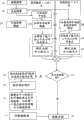
图7是在第一二次图像测量系统中使用的计算算法的流程图;Fig. 7 is the flowchart of the calculation algorithm used in the first secondary image measurement system;
图8是在第一二次图像测量系统中使用的真实性检查算法的流程图;Fig. 8 is a flowchart of the authenticity checking algorithm used in the first secondary image measurement system;
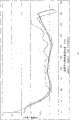
图9是示出测量的和计算的挡风玻璃的二次图像偏离角的比较的图表;9 is a graph showing a comparison of measured and calculated secondary image deflection angles for a windshield;
图10是用于使用第一二次图像测量系统的数据自动收集的设置的示意图;10 is a schematic diagram of a setup for automatic data collection using the first secondary image measurement system;
图11是在图10中使用的照相机支持台架的示意图;Figure 11 is a schematic illustration of the camera support gantry used in Figure 10;
图12是第二二次图像测量系统的示意图;以及12 is a schematic diagram of a second secondary image measurement system; and
图13是用于与第二二次图像测量系统一同使用的目标的示意图。13 is a schematic diagram of a target for use with the second secondary image measurement system.
具体实施方式Detailed ways
一种确保对二次图像特别是在玻璃窗边缘区域的二次图像的精确和可靠的测量的问题的解决方案是提供定量的测量系统,其中数据的获取和处理是自动的。这是在本发明第一方面中所采取的方法。A solution to the problem of ensuring an accurate and reliable measurement of secondary images, especially in the area of the edge of the glazing, is to provide quantitative measurement systems in which the acquisition and processing of the data is automated. This is the approach taken in the first aspect of the invention.
图4示出与定量的二次图像测量系统一起使用的目标29。阵列的三个发光二极管(LED)30、31、32沿着在250mm乘250mm尺寸的目标29上的以45°倾斜的线A-A′按60mm的间隔放置。在本例中的LED以3W的功率发射绿光。由于LED提供亮的、几乎点状的光源,所以,它们作为在光学测量系统中的光源LED是极其有用的。对于靠近玻璃窗边缘的测量,以某一角度倾斜的三个LED的阵列的使用是有利的。Figure 4 shows a
图5示出用于第一二次图像测量系统的实验设置。系统33包括其上安装目标35和LED阵列36的台架34。台架34在离玻璃窗37距离L的位置处放置。优选地,L=7.5m。CMOS(互补金属氧化物半导体)照相机(可以得自Basler AG,An der Strusbek 60-62,D-22926,Ahrensburg,Germany的A601f-HDR)被安装在三脚架39上。一个镜头安装(c-mount)、f=100mm的透镜40被用来将LED阵列36成像到CMOS照相机38上。通过抑制入射光的非反射成分,线性偏振器41被安装在透镜40和CMOS照相机38之间以便减少LED阵列36的主图像和二次图像之间的对比度。CMOS照相机38通过FireWireTM连接42连接到计算机(未示出)。计算机运行例如通过LabViewTM实现的实时图像捕获程序和下面讨论的处理算法。Figure 5 shows the experimental setup for the first secondary image measurement system. The
CMOS照相机38具有多个像素,每一个像素都包含将光转换为电荷的光电二极管、电荷到电压转换器、复位和选择晶体管以及放大器。由覆盖整个传感器的金属格栅提供定时和读出信号以及列输出信号互连的阵列。多路电子装置设置在像素阵列外的列中,并且连接到列线(column line)。使用X-Y寻址读出在阵列中的信号。The
由CMOS照相机38捕获的图像在图6中示出。三个亮点(brightspot)43、44、45可见,并且是LED阵列36的主图像。三个暗点(faintspot)46、47、48也可见,每一个暗点都与亮点43、44、45中最近的一个亮点保持恒定的偏转距离。这些是LED阵列36的二次图像,并且每一个都对应于亮点43、44、45中的一个。An image captured by
由于在阵列36中的LED之间的距离已知,所以基于主图像的分布,以mm/像素校准照相机像素是可能的。那么,使用mm/像素值来确定从任何二次图像点对应的亮点开始的该二次图像点的以mm计的偏转距离。那么,主图像和二次图像之间的偏离角使用下面公式来计算:Since the distance between the LEDs in the
θ=arctan(d/L),θ = arctan(d/L),
其中d和L都以mm计。对于上述例子,偏离角等于:Where d and L are in mm. For the above example, the deviation angle is equal to:
θ=arctan(d/7500)。θ = arctan (d/7500).
为了确定偏离角,二次图像测量系统必须能够定位亮的主图像点和暗的二次图像点的位置。对暗的二次图像点的检测在某些照明条件下可能会变得困难,例如,如果在要进行测量的房间里有太多的残余光,和/或如果该测量系统没有适当地设置。CMOS照相机38检测来自房间内其它光源的暗光点也是可能的。因此,该系统的一个主要任务是区别由LED阵列36产生的“真的”光点和由其它光源产生的“假的”光点。In order to determine the deviation angle, the secondary image measurement system must be able to locate the bright primary image points and the dark secondary image points. Detection of dark secondary image points may become difficult under certain lighting conditions, for example if there is too much residual light in the room where the measurement is to be made, and/or if the measurement system is not properly set up. It is also possible for the
该系统包括运行识别图像中的对象的算法并计算偏离角的计算机,这些对象是亮点和暗点。The system includes computers that run algorithms that identify objects in the image, which are bright and dark spots, and calculate the angle of deviation.
亮点可以简单地通过向照相机图像应用固定的阈值并选择三个最大的光点来找到。由于照明条件的可能的改变,暗的二次光点更难可靠地检测到。可以使用半自动阈值技术,其中图像的平均灰度与用户定义的阈值结合。以这样的方式,该系统可以轻易地适用于工作在不同的照明条件下。只有来自阈值图像的最小的三个光点被选择和保留用于进一步的处理。所用的算法也进行真实性检查,以便确定所选的光点是否适合于执行偏离角计算。但是,如下所述,优选的是,使用局部阈值的系统,其中,对于每一个局部区域,计算照明的平均值,并且应用与这一平均值相关的阈值。Bright spots can be found simply by applying a fixed threshold to the camera image and selecting the three largest points of light. Due to possible changes in lighting conditions, dark secondary light spots are more difficult to detect reliably. Semi-automatic thresholding techniques can be used, where the average gray level of the image is combined with a user-defined threshold. In this way, the system can be easily adapted to work in different lighting conditions. Only the smallest three blips from the thresholded image were selected and kept for further processing. The algorithm used also performs a plausibility check in order to determine whether the selected light spot is suitable for performing the deviation angle calculation. However, as described below, a system using local thresholding is preferred, wherein for each local area an average value of the illumination is calculated and a threshold associated with this average value is applied.
图7是示出该计算算法的流程图。在步骤101,亮点和暗点的图像被捕获。在步骤102,为了在处理中使用,该图像被复制。鉴于首先确定暗点和二次点的处理,在步骤103,使用第一图像用于,计算在局部区域中的所有可用像素的强度的平均值。这是通过计算在第一位置中的小正方形区域内的所有像素的第一平均强度值,将该正方形移动到第二位置并计算第二平均强度值来完成的。在步骤104,局部相关阈值105(对于这些点的强度,基于平均值)被计算并应用到每一个正方形。在步骤106,除了三个最小的点以外的所有的点都被去除。在步骤107,确定这些点的中心位置和大小。同时使用第二图像实现确定亮点的处理。在步骤108,确定并应用局部相关阈值。在步骤109,除了最亮的点以外的所有的点都被去除。在步骤110,确定这些点的中心位置和大小。来自两种处理的结果被结合,并在步骤111应用真实性检查。这种真实性检查在图8中进行更详细的描述。如果真实性检查的回答是“是”,算法继续进行步骤112,通过先X坐标后Y坐标位置对点进行分类。在步骤113,相应对的暗(二次)点和亮(主)点被结合。在步骤114,在中心的亮点和外部的亮点之间的距离,以及每一个亮点和对应的暗点之间的距离被测量。在步骤115,通过点之间的距离计算偏离角。一旦这一处理完成,该算法重新开始,并返回步骤112。如果真实性检查的回答是“否”,该算法重新开始,并返回步骤101。FIG. 7 is a flowchart showing the calculation algorithm. In
图8是示出真实性检查的流程图。该算法开始于步骤117。在步骤118,计算亮点和暗点的数量。在步骤119,如果亮点的数量和暗点的数量是三,该算法前进到步骤120。在步骤120,如果亮点之间的距离和暗点之间的距离大致相等,那么在步骤122返回成功并且真实性检查111回答“是”。如果点之间的距离不同,则在步骤123返回失败并且真实性检查111回答“否”。但是,如果在步骤119的回答是否,在步骤121,如果亮点的数量是至少两个并且暗点的数量是至少两个,那么该算法前进到步骤124。在步骤124,亮点之间的距离被计算并且与暗点之间的距离进行比较,以便确定两个暗点和两个亮点实际上是否是三个点阵列的外侧的两个点。如果在步骤124的回答是“是”,那么在步骤126返回成功,真实性检查111回答“是”。如果在步骤124的回答是“否”,那么在步骤125返回失败,真实性检查111说“否”。如果在步骤121的回答是“否”,那么在步骤125返回失败,真实性检查111回答“否”。Fig. 8 is a flow chart showing authenticity checking. The algorithm starts at step 117 . At step 118, the number of bright and dark spots is calculated. At step 119 , if the number of bright spots and the number of dark spots are three, the algorithm proceeds to step 120 . At step 120, if the distance between the bright spots and the distance between the dark spots are approximately equal, then at step 122 success is returned and the plausibility check 111 answers "Yes". If the distances between the points are different, a failure is returned at step 123 and the plausibility check 111 answers "No". However, if the answer at step 119 is no, then the algorithm proceeds to step 124 if the number of bright spots is at least two and the number of dark spots is at least two at step 121 . At step 124, the distance between the bright spots is calculated and compared to the distance between the dark spots to determine whether the two dark spots and the two bright spots are actually the outer two points of the three point array. If the answer at step 124 is "yes", then at step 126 success is returned and the authenticity check 111 answers "yes". If the answer at step 124 is "No", then at step 125 a failure is returned and the plausibility check 111 says "No". If the answer at step 121 is "No", then at step 125 a failure is returned and the plausibility check 111 answers "No".
一旦计算出偏离角,就通过连接到计算机的屏幕将该偏离角输出给操作者。Once the deflection angle is calculated, it is output to the operator via a screen connected to the computer.
为了确定该系统的准确性,进行两种测试以便确定该系统的准确性。首先,得自Optical Works Limited,Ealing Science Centre,Treloggan Lane,Newquay,Cornwall,TR71HX,UK的一系列光学参考光楔被用来确定该系统的偏差(bias)。该参考光楔使用通过由该系统测量的每个光楔生成的二次图像覆盖了0到30弧分的范围。执行两组测量,从而分别给出0.4弧分和0.3弧分的均方根误差。In order to determine the accuracy of the system, two tests were performed in order to determine the accuracy of the system. First, a series of optical reference wedges from Optical Works Limited, Ealing Science Centre, Treloggan Lane, Newquay, Cornwall, TR71HX, UK were used to determine the bias of the system. The reference wedge covers the range of 0 to 30 arc minutes using secondary images generated by each wedge measured by the system. Two sets of measurements were performed giving root mean square errors of 0.4 arc minutes and 0.3 arc minutes respectively.
其次,对于不同操作者造成的结果的不同进行检测。在挡风玻璃上定义了六个大小为40mm x 40mm的测量区。四名操作者被要求对每个部分进行三次测量,结果记录在下面的表1中。每一个测量结果都是以弧分计。Second, detect the difference in results caused by different operators. Six measurement areas of size 40mm x 40mm are defined on the windshield. Four operators were asked to perform three measurements on each section, and the results are reported in Table 1 below. Each measurement is in arc minutes.

表1由四个操作者进行的二次图像测量及其范围Table 1 Secondary image measurements and their ranges by four operators
对于重复性(repeatability)的估计的标准差σe,即,在每个操作者的读数(reading)中的变异(variation)由下式给出:The estimated standard deviation σe for repeatability, ie, the variation in each operator's readings, is given by:
其中R_BAR是范围的平均值(其中该范围是在每个给定部分上每个操作员的最大读数和最小读数之间的差),d2是由在样本中的项目数确定的常量,例如参见“Business Statistics An IntroductoryCourse”,by Ken Black,ISBN0-314-92219-9。where R_BAR is the mean of the range (where the range is the difference between the maximum and minimum readings for each operator on each given section), andd2 is a constant determined by the number of items in the sample, e.g. See "Business Statistics An Introductory Course", by Ken Black, ISBN 0-314-92219-9.
重复性由下式给出Repeatability is given by
重复性=5.15 x σe=0.78Repeatability = 5.15 x σe = 0.78
其中5.15是常量,表示正常分布的99%的结果。where 5.15 is a constant representing 99% of the results for a normal distribution.
通过找到每个操作者的全部的平均值,然后通过从最大的平均值减去最小的平均值得到的操作者平均值的范围R0来确定再现性(reproducibility)或者操作者之间的变异。从上述表1中给出的数字,Reproducibility, or inter-operator variation, was determined by finding the overall mean for each operator, then the rangeR0 of the operator mean by subtracting the smallest mean from the largest mean. From the figures given in Table 1 above,
Ro=10.24-10.22=0.22Ro =10.24-10.22=0.22
因此,估计的操作者标准差为:Therefore, the estimated operator standard deviation is:
并且再现性为and the reproducibility is
考虑到计量变异(gauge variation),调整后的再现性给出为:Taking into account gauge variation, the adjusted reproducibility is given as:
其中n是部分的数目,r是试验次数。因此,经调整后的操作者标准差为:where n is the number of sections and r is the number of trials. Therefore, the adjusted operator standard deviation is:
并且,测量系统的标准差,σm是And, the standard deviation of the measurement system,σm , is
计量系统变异为The metering system mutates to
5.15 x σm=0.91。5.15 xσm = 0.91.
因此,计量系统变异由仪器自身主导,而不是由操作员主导。因此,与现有技术系统不同,所测量的偏离角的精度实际上不受进行测量的操作员的影响。Therefore, metrology system variation is led by the instrument itself, not by the operator. Thus, unlike prior art systems, the accuracy of the measured deviation angle is virtually independent of the operator making the measurement.
基于CNC测量,使用本发明第一方面的二次图像传输系统进行的测量也已经与计算机模型预测进行了比较。图9是示出了使用二次图像测量系统(“SIMA 1”和“SIMA 2”)进行的两种测量怎样与沿挡风玻璃的垂直轴进行的两种计算(“CNC 1”和“CNC 2”)进行比较。示出的x轴的刻度以Omm作为挡风玻璃的顶端。可以看出,使用二次图像测量系统进行的测量是可重复和精确的,并且在量级上与基于CNC测量的模型计算相符。造成测量和计算之间的差别的一种可能的原因是二次图像测量系统进行读数的点的间隔比CNC测量系统的紧密得多。这导致通过模型实现二次图像数据的一定的平滑(smoothing),该模型使用二次图像测量系统来检测。Measurements made using the secondary image transmission system of the first aspect of the invention have also been compared with computer model predictions based on CNC measurements. Figure 9 is a diagram showing how two measurements made using secondary image measurement systems (“
使用该系统提供单独一次的测量或者进行一系列的测量以便产生概貌是可能的。通过手工重新放置该玻璃窗和/或照相机和目标,或者通过使数据收集自动化,对整个玻璃窗上的一系列点进行测量可以产生这样的概貌。可以使用该系统检验单层玻璃和叠层玻璃窗,其中,单层玻璃例如为钢化玻璃(toughened glass),叠层玻璃窗通常包括其间层叠有中间层的两层退火玻璃。在叠层玻璃窗中,作为玻璃单层或玻璃叠层厚度不同的后果,可能出现偏离角。It is possible to use the system to provide a single measurement or to perform a series of measurements in order to generate an overview. Such an overview can be generated by taking measurements of a series of points across the glazing by manually repositioning the glazing and/or the camera and target, or by automating data collection. The system can be used to inspect single panes of glass, such as toughened glass, as well as laminated glazing, which typically includes two plies of annealed glass with an interlayer laminated therebetween. In laminated glazing, deflection angles may occur as a consequence of differences in the thickness of the glass individual layers or of the glass stack.
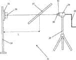
图10是用于自动数据收集的二次图像测量系统的示意图。系统49包括安装在由台架52支撑的目标51上的LED阵列50。玻璃窗53安装在台架54上,该台架允许其位置在X和Y方向变化,并在以倾角
图11是支持台架56的前视图。该支持台架包括外部框架58和支持构件59。照相机55借助于球窝枢轴(ball and socket pivot)60安装到支持构件上。枢轴60使得照相机可以倾斜以便确保照相机55、玻璃窗53和LED阵列50之间精确的对准。附在照相机55上的是两个激光指示器61、62。激光指示器61、62用来识别测量点,并且也用于辅助照相机55的对准。支持构件59的形式是垂直滑板(slide),从而使照相机55可以移动到构件59的任何位置并就地固定。支持构件59在支撑框架58中的导轨上是能够从一边移动另一边的,以便允许在玻璃窗的全部区域上进行光栅扫描测量。测量点相距大约100mm的玻璃窗的2-D图像需要小于30分钟来执行。计算机运行算法并允许操作者定位计算机。这种定位可以作为手工输入命令或由计算机运行的程序的结果。FIG. 11 is a front view of the
尽管在上述系统中,使用包括三个LED的目标,该系统还是能够与具有两个LED的目标工作,并且对不同处理的算法能够进行适当的调整。在上述例子中,CMOS照相机已经被用作了图像捕获装置。但是,使用CCD(电荷耦合装置)照相机作为图像捕获装置也是可能的。Although in the system described above a target comprising three LEDs was used, the system can work with targets having two LEDs and the algorithms for different treatments can be properly adjusted. In the above examples, a CMOS camera has been used as the image capturing means. However, it is also possible to use a CCD (Charge Coupled Device) camera as the image capture device.
该二次图像测量系统比现有技术的目标和准直测试提供更多的优点。可以得到对偏离角的精确的、定量的测量,以及对被检测的玻璃窗的整个的概貌。该测量过程可以是自动的。另外,对玻璃窗的定位可以是自动的,例如,使用机器人将玻璃窗放置到要进行测试的支持台架上。这使得系统能够被包含在生产线中。This secondary image measurement system offers several advantages over prior art target and alignment tests. Accurate, quantitative measurements of the deflection angle can be obtained, as well as an overall overview of the inspected glazing. This measurement process can be automated. Additionally, the positioning of the glazing may be automated, for example using a robot to place the glazing on a support stand to be tested. This enables the system to be included in production lines.
本发明的第二方面提供对偏离角定量问题的另一解决方案,特别地,如图12和图13所示,在玻璃窗的边缘区域。图12示出第二二次图像系统的示例性设置。整个设置与图2a中示出的相似。设置在距离目标64距离S的观察者63通过玻璃窗65观察目标64。目标64由例如绿LED的LED 66在中心处被照射。S优选地大于或等于7m。图13示出在第二二次图像测量系统中使用的目标。目标64包含以2弧分间隔放置的一系列同心环67。10弧分环68和20弧分环69以不同颜色示出。这可以通过对目标进行适当地着色或照射来实现。当通过其中存在变形的玻璃窗观察时,LED 66的二次图像70被看到,从目标64的中心偏离一定数量的环67。该偏离角由二次图像70落在上面或最靠近的环67来确定,导致±1弧分的精确度。该系统可以由操作者使用,例如,通过一副双筒望远镜或其它成像装置来进行手工测量。由于在不需要复杂的光学设置的情况下,该第二二次图像测量系统给出了对偏离角的简单的定量测量,因此其在目标测试和准直测试上都有优点。该系统可以用来替代上述第一二次图像测量系统或与上述第一二次图像测量系统一前一后使用,来拍摄(screen)玻璃窗以便进行进一步的测试。可以使用该系统检验单层玻璃和叠层玻璃窗,其中,单层玻璃例如为钢化玻璃,叠层玻璃窗通常包括其间层叠有中间层的两层退火玻璃。在叠层玻璃窗中,作为玻璃单层或玻璃叠层厚度不同的后果,可能出现偏离角。The second aspect of the invention provides another solution to the problem of off-angle quantification, in particular, as shown in Figures 12 and 13, in the edge region of the glazing. Fig. 12 shows an exemplary setup of a second secondary image system. The whole setup is similar to that shown in Figure 2a. An
优选地,使用一种或两种系统进行测试的玻璃窗是挡风玻璃。但是,这些系统可以用来测试导致在其它自动玻璃窗中产生二次图像的变形和缺陷,所述玻璃窗,例如,是后窗玻璃(backlight)、侧窗玻璃(sidelight)和顶窗玻璃(toplight),或者其它玻璃窗,例如建筑物上的玻璃窗。Preferably, the glazing tested using one or both systems is a windshield. However, these systems can be used to test for distortions and defects that cause secondary images in other automatic glazing, such as backlight, sidelight and roof glazing ( toplight), or other glass windows, such as those on buildings.
Claims (24)
Translated fromChineseApplications Claiming Priority (2)
| Application Number | Priority Date | Filing Date | Title |
|---|---|---|---|
| GBGB0610148.9AGB0610148D0 (en) | 2006-05-23 | 2006-05-23 | Glazing inspection method |
| GB0610148.9 | 2006-05-30 |
Publications (1)
| Publication Number | Publication Date |
|---|---|
| CN101479596Atrue CN101479596A (en) | 2009-07-08 |
Family
ID=36660624
Family Applications (1)
| Application Number | Title | Priority Date | Filing Date |
|---|---|---|---|
| CNA2007800238677APendingCN101479596A (en) | 2006-05-23 | 2007-05-22 | Glazing inspection method |
Country Status (7)
| Country | Link |
|---|---|
| US (1) | US8165382B2 (en) |
| EP (1) | EP2030005A2 (en) |
| JP (1) | JP2009544002A (en) |
| CN (1) | CN101479596A (en) |
| BR (1) | BRPI0711890A2 (en) |
| GB (1) | GB0610148D0 (en) |
| WO (1) | WO2007135465A2 (en) |
Cited By (6)
| Publication number | Priority date | Publication date | Assignee | Title |
|---|---|---|---|---|
| CN102706899A (en)* | 2012-06-05 | 2012-10-03 | 福耀玻璃工业集团股份有限公司 | System and method for detecting secondary image of automobile glass |
| CN107525656A (en)* | 2017-09-15 | 2017-12-29 | 上海汽车集团股份有限公司 | Imaging independent positioning method of the illuminator in glass for vehicle window |
| CN109716111A (en)* | 2016-08-04 | 2019-05-03 | 伊斯拉表面视觉有限公司 | For determining the device and method at ghost image angle and/or visual angle |
| CN110345861A (en)* | 2019-06-06 | 2019-10-18 | 中国建材检验认证集团股份有限公司 | It is telescope, secondary as deviation value test device and pair are as deviation value test macro |
| CN110895824A (en)* | 2018-09-12 | 2020-03-20 | 上海耕岩智能科技有限公司 | Method for automatically searching thickness parameter of display screen, storage medium and electronic equipment |
| CN112362308A (en)* | 2020-10-27 | 2021-02-12 | 中国建材检验认证集团股份有限公司 | Method and device for measuring secondary image deviation value, dial and target type light source instrument |
Families Citing this family (7)
| Publication number | Priority date | Publication date | Assignee | Title |
|---|---|---|---|---|
| GB0610148D0 (en) | 2006-05-23 | 2006-06-28 | Pilkington Automotive D Gmbh | Glazing inspection method |
| CN102879080B (en)* | 2012-09-11 | 2014-10-15 | 上海交通大学 | Sound field analysis method based on image recognition positioning and acoustic sensor array measurement |
| GB201309549D0 (en)* | 2013-05-29 | 2013-07-10 | Pilkington Group Ltd | Glazing |
| DE202013008910U1 (en)* | 2013-10-07 | 2015-01-09 | MÖLLER-WEDEL OPTICAL GmbH | Device for measuring windows, in particular windshields of vehicles |
| DE202013008909U1 (en)* | 2013-10-07 | 2015-01-09 | MÖLLER-WEDEL OPTICAL GmbH | Device for measuring windows, in particular windshields of vehicles |
| DE102016218663B4 (en) | 2016-09-28 | 2018-06-14 | Audi Ag | Method for the areal measurement of the wedge angle of a light-transparent pane |
| WO2020033967A1 (en)* | 2018-08-10 | 2020-02-13 | Buffalo Automation Group Inc. | Training a deep learning system for maritime applications |
Family Cites Families (16)
| Publication number | Priority date | Publication date | Assignee | Title |
|---|---|---|---|---|
| DE2310763C3 (en) | 1973-03-03 | 1980-04-24 | Vereinigte Flugtechnische Werkefokker Gmbh, 2800 Bremen | Method for testing the optical quality of transparent panes |
| US4249823A (en)* | 1979-10-16 | 1981-02-10 | The United States Of America As Represented By The Secretary Of The Air Force | Windscreen angular deviation measurement device |
| US4461570A (en) | 1982-06-09 | 1984-07-24 | The United States Of America As Represented By The Secretary Of The Air Force | Method for dynamically recording distortion in a transparency |
| GB8424074D0 (en) | 1984-09-24 | 1984-10-31 | British Aerospace | Testing light transmitting articles |
| US4837449A (en)* | 1988-05-16 | 1989-06-06 | Maltby Jr Robert E | Inspecting for matching of paired sheets of transparent material |
| FR2663744B1 (en)* | 1990-06-25 | 1993-05-28 | Saint Gobain Vitrage Int | METHOD AND DEVICE FOR MEASURING THE OPTICAL QUALITY OF A GLAZING. |
| CA2095303A1 (en)* | 1992-05-06 | 1993-11-07 | Atsushi Miyake | System of detecting optical distortion of a light-transmitting platelike member |
| US5343288A (en) | 1992-11-23 | 1994-08-30 | Libbey-Owens-Ford Co. | Optical evaluation of automotive glass |
| US5621520A (en)* | 1996-05-13 | 1997-04-15 | Northrop Grumman Corporation | Transparency inspection method for blurriness in vehicle windscreens with elastomeric liners |
| US5726749A (en)* | 1996-09-20 | 1998-03-10 | Libbey-Owens-Ford Co. | Method and apparatus for inspection and evaluation of angular deviation and distortion defects for transparent sheets |
| US20020154298A1 (en)* | 2001-04-24 | 2002-10-24 | International Business Machines Corporation | Method of inspecting an edge of a glass disk for anomalies in an edge surface |
| FR2846096B1 (en) | 2002-10-16 | 2005-02-11 | DEVICE FOR DETECTING, ANALYZING AND LOCATING DEFECTS PRESENTED ON TRANSPARENT AND / OR REFLECTIVE SURFACE | |
| GB0307345D0 (en) | 2003-03-29 | 2003-05-07 | Pilkington Plc | Glazing inspection |
| NZ545707A (en)* | 2003-09-16 | 2008-06-30 | Paper Australia Pty Ltd | Sheet-surface analyser and method of analysing a sheet-surface (such as paper) |
| JPWO2006095519A1 (en)* | 2005-03-07 | 2008-08-14 | 日本板硝子株式会社 | Perspective distortion inspection apparatus and inspection method for light transmissive panel |
| GB0610148D0 (en) | 2006-05-23 | 2006-06-28 | Pilkington Automotive D Gmbh | Glazing inspection method |
- 2006
- 2006-05-23GBGBGB0610148.9Apatent/GB0610148D0/ennot_activeCeased
- 2007
- 2007-05-22JPJP2009511586Apatent/JP2009544002A/enactivePending
- 2007-05-22USUS12/301,787patent/US8165382B2/enactiveActive
- 2007-05-22EPEP07733703Apatent/EP2030005A2/ennot_activeWithdrawn
- 2007-05-22CNCNA2007800238677Apatent/CN101479596A/enactivePending
- 2007-05-22WOPCT/GB2007/050282patent/WO2007135465A2/enactiveApplication Filing
- 2007-05-22BRBRPI0711890-2Apatent/BRPI0711890A2/ennot_activeIP Right Cessation
Cited By (10)
| Publication number | Priority date | Publication date | Assignee | Title |
|---|---|---|---|---|
| CN102706899A (en)* | 2012-06-05 | 2012-10-03 | 福耀玻璃工业集团股份有限公司 | System and method for detecting secondary image of automobile glass |
| CN102706899B (en)* | 2012-06-05 | 2014-03-26 | 福耀玻璃工业集团股份有限公司 | System and method for detecting secondary image of automobile glass |
| CN109716111A (en)* | 2016-08-04 | 2019-05-03 | 伊斯拉表面视觉有限公司 | For determining the device and method at ghost image angle and/or visual angle |
| CN109716111B (en)* | 2016-08-04 | 2022-01-07 | 伊斯拉表面视觉有限公司 | Device and method for determining ghost angles and/or viewing angles |
| CN107525656A (en)* | 2017-09-15 | 2017-12-29 | 上海汽车集团股份有限公司 | Imaging independent positioning method of the illuminator in glass for vehicle window |
| CN107525656B (en)* | 2017-09-15 | 2019-07-26 | 上海汽车集团股份有限公司 | Method for locating imaging point of illuminant on window glass |
| CN110895824A (en)* | 2018-09-12 | 2020-03-20 | 上海耕岩智能科技有限公司 | Method for automatically searching thickness parameter of display screen, storage medium and electronic equipment |
| CN110895824B (en)* | 2018-09-12 | 2023-03-28 | 上海耕岩智能科技有限公司 | Method for determining thickness parameter of display screen, storage medium and electronic equipment |
| CN110345861A (en)* | 2019-06-06 | 2019-10-18 | 中国建材检验认证集团股份有限公司 | It is telescope, secondary as deviation value test device and pair are as deviation value test macro |
| CN112362308A (en)* | 2020-10-27 | 2021-02-12 | 中国建材检验认证集团股份有限公司 | Method and device for measuring secondary image deviation value, dial and target type light source instrument |
Also Published As
| Publication number | Publication date |
|---|---|
| WO2007135465A2 (en) | 2007-11-29 |
| US8165382B2 (en) | 2012-04-24 |
| GB0610148D0 (en) | 2006-06-28 |
| EP2030005A2 (en) | 2009-03-04 |
| WO2007135465A3 (en) | 2008-01-17 |
| BRPI0711890A2 (en) | 2012-01-10 |
| JP2009544002A (en) | 2009-12-10 |
| US20100232677A1 (en) | 2010-09-16 |
Similar Documents
| Publication | Publication Date | Title |
|---|---|---|
| CN101479596A (en) | Glazing inspection method | |
| US20210341353A1 (en) | System and method for inspecting optical power and thickness of ophthalmic lenses immersed in a solution | |
| CN102023164B (en) | For detecting the apparatus and method of the local defect of transparent plate | |
| US8415648B2 (en) | Method of determination of glass surface shapes and optical distortion by reflected optical imaging | |
| US6392754B1 (en) | Method and apparatus for measuring the profile of reflective surfaces | |
| US5726749A (en) | Method and apparatus for inspection and evaluation of angular deviation and distortion defects for transparent sheets | |
| US11650126B2 (en) | Systems and methods for automatic visual inspection of defects in ophthalmic lenses | |
| CN111638226B (en) | Detection method, image processor and detection system | |
| US5128550A (en) | Method of and an apparatus for testing large area panes for optical quality | |
| JP2007501942A (en) | Optical test method and optical test apparatus for optically controlling the quality of an object preferably having a circular edge | |
| RU2769373C1 (en) | Method of measuring geometrical discrepancies between curved surfaces of a plurality of analyzed materials and a curved surface of a reference material | |
| US5146282A (en) | Process and device for measuring the optical quality of a glazing | |
| JPH09229819A (en) | Method and instrument for measuring lens parameter using optical section | |
| CN110208269A (en) | The method and system that a kind of glass surface foreign matter and internal foreign matter are distinguished | |
| CN109425619B (en) | Optical measurement system and method | |
| CN113686903A (en) | Optical element defect detection system and detection method | |
| KR20050035243A (en) | Optical measuring method and device therefor | |
| CN104180772A (en) | Visual inspection device | |
| KR102188568B1 (en) | Display panel inspection method based on artificial intelligence | |
| US20130162816A1 (en) | Device for measuring the shape of a mirror or of a specular surface | |
| CN111220621A (en) | Chip inclined surface detection method | |
| JPH08178855A (en) | Inspection method for translucent or specular objects | |
| JP2001124538A (en) | Method and device for detecting defect in surface of object | |
| CN113176076A (en) | Optical detection system and optical detection method | |
| JPH07306152A (en) | Optical distortion inspecting device |
Legal Events
| Date | Code | Title | Description |
|---|---|---|---|
| C06 | Publication | ||
| PB01 | Publication | ||
| C10 | Entry into substantive examination | ||
| SE01 | Entry into force of request for substantive examination | ||
| C02 | Deemed withdrawal of patent application after publication (patent law 2001) | ||
| WD01 | Invention patent application deemed withdrawn after publication | Open date:20090708 |