CN101477405B - Steady state visually evoked brain-computer interface method based on two frequency stimuli in the left and right visual fields - Google Patents
Steady state visually evoked brain-computer interface method based on two frequency stimuli in the left and right visual fieldsDownload PDFInfo
- Publication number
- CN101477405B CN101477405BCN2009100762095ACN200910076209ACN101477405BCN 101477405 BCN101477405 BCN 101477405BCN 2009100762095 ACN2009100762095 ACN 2009100762095ACN 200910076209 ACN200910076209 ACN 200910076209ACN 101477405 BCN101477405 BCN 101477405B
- Authority
- CN
- China
- Prior art keywords
- brain
- frequency
- target
- visual
- stimulation
- Prior art date
- Legal status (The legal status is an assumption and is not a legal conclusion. Google has not performed a legal analysis and makes no representation as to the accuracy of the status listed.)
- Expired - Fee Related
Links
Images


Landscapes
- Measurement And Recording Of Electrical Phenomena And Electrical Characteristics Of The Living Body (AREA)
Abstract
Description
Translated fromChinese技术领域technical field
本发明属于人机交互技术领域,可帮助残障人士操作计算机等外部设备,也可用于新型的脑机交互的电子娱乐。The invention belongs to the technical field of human-computer interaction, can help disabled people operate external devices such as computers, and can also be used for new electronic entertainment of brain-computer interaction.
背景技术Background technique
脑-机接口系统是一种不需要外周肌肉与神经参与的通讯系统,它旨在建立一个人脑与外周世界的直接交流通道,通过提取脑电信号中的特征,从而将识别出的大脑指令或者信息传递给被控制的外部设备,最终完成大脑对外部设备的直接控制。脑电信号通常采用非侵入式头皮脑电记录获得。The brain-computer interface system is a communication system that does not require the participation of peripheral muscles and nerves. It aims to establish a direct communication channel between the human brain and the peripheral world. Or the information is transmitted to the controlled external device, and finally the brain directly controls the external device. EEG signals are usually obtained using non-invasive scalp EEG recordings.
视觉稳态诱发电位是脑-机接口BCI经常使用的一种信号,它是大脑视觉皮层对于外界大于6Hz闪烁刺激的响应信号,通过提取枕区脑电信号可以获得。相对于基于其它信号的脑-机接口系统而言,基于稳态视觉诱发电位的脑-机接口通常具有更高的信息传输率,更兼有系统简便,仅需要较少训练的优点。为了使得脑-机接口系统更便携、实用,使用计算机屏幕作为刺激手段是一个不错的方法,但是在使用计算机屏幕作为目标呈现方式时,由于固有刷新率的问题,激发稳态视觉诱发电位的频率可选范围很小,使得目标呈现数量有限。在对于残疾人的使用上,较少的目标意味着选择层次的增加,这将增加使用者的疲劳程度,和系统菜单的复杂程度。Visual steady-state evoked potential is a signal often used in brain-computer interface BCI. It is the response signal of the visual cortex of the brain to external flickering stimuli greater than 6 Hz. It can be obtained by extracting the EEG signal in the occipital region. Compared with brain-computer interface systems based on other signals, brain-computer interfaces based on steady-state visual evoked potentials usually have a higher information transmission rate, and are more convenient and require less training. In order to make the brain-computer interface system more portable and practical, it is a good way to use a computer screen as a stimulus, but when using a computer screen as a target presentation method, due to the inherent refresh rate problem, the frequency of stimulating the steady-state visual evoked potential The range of options is small, resulting in a limited number of target presentations. For disabled users, fewer objects mean an increased level of choice, which increases user fatigue and system menu complexity.
中国专利“基于瞬态视觉诱发电位提取脑机接口信号的方法”(200310121033.3),以及“基于脑电稳态诱发响应的控制系统”(99122161.3)采用的是传统的稳态视觉诱发电位目标呈现方式,其中一个发光二极板形成一个目标,该发光二极板以固定的频率闪烁,使用者使注视该目标时,通过计算脑电信号的快速傅立叶变换可以得到对应频率的峰图。一个发光二极板使用一个频率,形成一个目标,因此采用n个频率可以形成n个目标。如果以普通的显示器为视觉刺激设备,由于受到屏幕刷新率的限制,只有较少的几个频率可用。Chinese patents "Method for Extracting Brain-Computer Interface Signals Based on Transient Visual Evoked Potentials" (200310121033.3) and "Control System Based on EEG Steady-state Evoked Responses" (99122161.3) use the traditional steady-state visual evoked potential target presentation method , wherein one light-emitting diode plate forms a target, and the light-emitting diode plate flickers at a fixed frequency. When the user looks at the target, the electropherogram of the corresponding frequency can be obtained by calculating the fast Fourier transform of the EEG signal. One light-emitting diode board uses one frequency to form one target, so n frequencies can be used to form n targets. If an ordinary display is used as a visual stimulation device, only a few frequencies are available due to the limitation of the screen refresh rate.
本发明提出采用左右视野双频刺激的目标呈现方式。利用神经生理学上早已证明的左右视野交叉原理,使用两个发光二极板用两个频率同时刺激,合成一个目标。在大脑枕区利用典型相关分析方法检测左右部分的频率成分。通过左右视野的频率组合,n个频率可以形成n的平方个目标数,比传统的目标呈现方式所能实现的目标数目提高了n倍。具有很大的理论研究和实际应用意义。The present invention proposes a target presentation mode using dual-frequency stimulation of the left and right visual fields. Using the long-proven neurophysiological crossover principle of the left and right visual fields, two light-emitting diodes are used to stimulate at the same time with two frequencies to synthesize a target. In the occipital region of the brain, the frequency components of the left and right parts were detected by canonical correlation analysis. Through the frequency combination of the left and right visual fields, n frequencies can form n square targets, which is n times higher than the number of targets that can be achieved by traditional target presentation methods. It has great theoretical research and practical application significance.
发明内容Contents of the invention
本发明在稳态视觉诱发电位的经典刺激模式的基础上提出了一种新的目标呈现方法,可以采用有限的频率资源实现更多的目标辨识。The present invention proposes a new target presentation method based on the classic stimulation mode of the steady-state visual evoked potential, which can realize more target recognition by using limited frequency resources.
本发明的特征在于,该方法依次含有以下步骤:The present invention is characterized in that the method contains the following steps in sequence:
步骤1,把脑电测试电极放在使用者头部枕区P1~P8、PO3~PO8、O1、O2位置,把参考电极放在该使用者的耳部,接地电极接地,所述测试电极得到的脑电信号经放大和模/数变换后送往计算机的USB接口;
步骤2,将两个大小适中的闪烁发光块放置于使用者前方下述位置:以双眼中心为焦点,左右摆设,间距为1cm左右,闪烁发光块的中间位置为使用者注视焦点,选定频率A和频率B,频段都为8~13Hz,所述左右闪烁发光块分别以所述频率A或B不断闪烁,以此,所述两个闪烁发光块组合成为一个目标,根据左右不同组合呈现4种目标,即:左右两个闪烁发光块的频率都为A或B,以及分别为频率A或频率B;
步骤3,根据步骤2,使用所述两个闪烁发光块按照组合,形成4种目标后,按以下步骤进行:Step 3, according to
步骤31,使用者注视所述4种目标中的任一个;Step 31, the user gazes at any one of the four targets;
步骤32,所述计算机在发出并口同步信号同时,通过所述测试电极记录脑电波,分别使用相关分析方法计算大脑枕区左右两半部分与刺激频率的相关系数,依次包含以下操作:首先对脑电波作滤波处理,以排除50Hz工频干扰;其次作基线处理,去除基线漂移使各脑电波都成为平稳的,均值接近为0的信号;再次,减少眼电伪迹,去掉包含眼动的刺激所对应的数据;然后,把每次脑电电位的刺激时刻对齐,分别选取枕区左右两半部分脑电信号作为两个集合;最后,所述计算机根据刺激频率和左右两半部分脑电信号做相关分析提取频率成分信息;Step 32, when the computer sends out the synchronous signal of the parallel port, record the brain waves through the test electrodes, respectively use the correlation analysis method to calculate the correlation coefficient between the left and right halves of the occipital area of the brain and the stimulation frequency, which includes the following operations in turn: The electric waves are filtered to eliminate 50Hz power frequency interference; secondly, baseline processing is performed to remove baseline drift so that each brain wave becomes a stable signal with an average value close to 0; thirdly, reduce electroocular artifacts and remove eye movement stimuli The corresponding data; then, the stimulation time of each EEG potential is aligned, and the left and right halves of the occipital region are respectively selected as two sets of EEG signals; finally, the computer according to the stimulation frequency and the left and right halves of the EEG signals Do correlation analysis to extract frequency component information;
步骤33,根据计算所得的所述相关系数的大小,判断出使用者所注视的目标;Step 33, according to the size of the calculated correlation coefficient, determine the target that the user is looking at;
步骤34:所述计算机根据检测出的目标进行相应的视觉反馈提示;Step 34: The computer provides corresponding visual feedback prompts according to the detected target;
步骤35:若顺利完成目标选择,则返回步骤32,重复步骤32-35,进行下一轮选择。Step 35: If the target selection is successfully completed, return to step 32, repeat steps 32-35, and proceed to the next round of selection.
经实验证明,本发明具有以下优点:Experiments have proved that the present invention has the following advantages:
(1)基于稳态视觉诱发电位,故具有稳态视觉诱发电位脑-机接口的优点,即:传输速率高,仅需较少的训练,设备简单。(1) Based on the steady-state visual evoked potential, it has the advantages of the steady-state visual evoked potential brain-computer interface, namely: high transmission rate, less training required, and simple equipment.
(2)同时在(1)基础上,使用左右视野两个频率的刺激模式来构造目标,则可以大幅提高目标数目。(2) On the basis of (1) at the same time, using stimulation patterns of two frequencies in the left and right visual fields to construct targets, the number of targets can be greatly increased.
(3)对于普遍人信噪比高的α频段,所能使用的频率非常有限,而使用该目标呈现方式,可以在信噪比高的α频段构造更多的目标。(3) For the α-frequency band with a high SNR of ordinary people, the frequencies that can be used are very limited, but using this target presentation method, more targets can be constructed in the α-frequency band with a high SNR.
(4)采用脑电记录方法,是无创无损的方法。(4) The EEG recording method is adopted, which is a non-invasive and non-destructive method.
附图说明Description of drawings
图1目标刺激模式图;Fig. 1 target stimulation mode diagram;
图2导联选择示意图;Figure 2 Schematic diagram of lead selection;
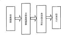
图3目标识别策略框图;Fig. 3 Target recognition strategy block diagram;
图4脑电波检测结果示例;Figure 4 Example of brain wave detection results;
图5典型相关分析系数比较图。Figure 5. Comparison chart of typical correlation analysis coefficients.
具体实施方式Detailed ways
本文发明的刺激模式见图1所示。十字叉左右两边的刺激块距离十字叉各为0.5cm,刺激块大小为3cm×6cm。A刺激块位于受试的左视野区,B刺激块位于右视野。两个刺激块组合成一个目标,受试注视十字叉位置,而常规的稳态视觉诱发脑机接口采用一个频率闪烁块呈现目标。根据神经科学的视野交叉原理,两个视野的频率成分将分别投影在大脑枕区左右两半部分,图中的字母‘A’、‘B’标识了投影的对应关系。The stimulation mode of the invention is shown in FIG. 1 . The distance between the stimulation blocks on the left and right sides of the cross is 0.5cm, and the size of the stimulation block is 3cm×6cm. The A stimulus block is located in the left visual field of the subject, and the B stimulus block is located in the right visual field. Two stimulus blocks are combined to form a target, and the subjects fixate on the position of the cross, while the conventional steady-state visually evoked BCI uses a frequency flicker block to present the target. According to the principle of visual field intersection in neuroscience, the frequency components of the two visual fields will be projected on the left and right halves of the occipital area of the brain respectively. The letters 'A' and 'B' in the figure indicate the corresponding relationship of projection.
这里以14、18Hz两个频率为例。两个频率按照左右视野组合,则可形成2种不同的目标,再加上左右视野使用相同频率形成的目标,最终共可呈现4种目标,如表1所示,其中目标1和目标2左右视野的刺激频率不相同,目标3和目标4左右视野分别采用了相同的刺激频率。Here we take the two frequencies of 14 and 18Hz as an example. Combining the two frequencies according to the left and right visual fields, two different targets can be formed. In addition to the targets formed by the same frequency in the left and right visual fields, a total of 4 types of targets can be presented, as shown in Table 1, among which
表1目标的频率组合及投影关系Table 1 Frequency combination and projection relationship of targets

常规的稳态视觉诱发脑机接口利用两个频率只能呈现两个目标,即,目标3和目标4两个目标。而采用左右视野两个频率同时刺激的的方法,系统可以多出两个目标,即,目标1和目标2的形式。Conventional steady-state visually evoked BCIs can only present two targets with two frequencies, namely, two targets, target 3 and target 4 . However, by using the method of simultaneously stimulating two frequencies of the left and right visual fields, the system can have two more targets, namely, the form of
使用者的脑电信号采用通用的脑电记录设备,采样频率为1000Hz。记录时采用64个导联,导联位置按照国际惯例10-20系统。参考电极位于左右乳突位置。The user's EEG signals are recorded using general-purpose EEG recording equipment with a sampling frequency of 1000 Hz. 64 leads were used for recording, and the lead position was in accordance with the international practice 10-20 system. Reference electrodes are located at the left and right mastoids.
使用者只要注视所有选择的目标的中心十字叉的位置,其脑后部视觉区域记录到的脑电信号就会包含使用者所注视目标的组合频率A和B的信息。通过以下方法可以检测出这些信息,并判断出使用者注视的目标。As long as the user gazes at the central cross positions of all selected objects, the EEG signal recorded in the visual area at the back of the brain will contain the combined frequency A and B information of the objects the user gazes at. This information can be detected by the following methods, and the target of the user's gaze can be determined.
典型相关分析(Canonical Correlation Analysis,CCA)是研究两组多维变量之间线性关系的一种统计方法,它将简单相关分析拓展到了两组变量的范畴。其最终目标是寻找两个线性组合,使得两组多维变量通过此线性组合后,其相关系数最大。这个相关系数描述了两组数据集合的关系。CCA在实际问题的研究中得到了广泛的应用,在脑电数据分析中同样也是适用的。对于脑电数据使用CCA方法,两组数据集合分别来自脑电信号和刺激信号。记试验采集的n导联脑电数据为Canonical Correlation Analysis (CCA) is a statistical method to study the linear relationship between two groups of multidimensional variables, which extends the simple correlation analysis to the category of two groups of variables. Its ultimate goal is to find two linear combinations, so that the correlation coefficient of two sets of multidimensional variables is the largest after this linear combination. This correlation coefficient describes the relationship between two sets of data. CCA has been widely used in the research of practical problems, and it is also applicable in the analysis of EEG data. For the EEG data, the CCA method is used, and the two sets of data sets come from the EEG signal and the stimulation signal respectively. Note that the n-lead EEG data collected by the test is
x=(x1 x2 x3...xn),x=(x1 x2 x3 ... xn ),
刺激信号为The stimulus signal is
y=(cos2πft sin2πft cos4πft sin4πft cos6πft sin6πft),y=(cos2πft sin2πft cos4πft sin4πft cos6πft sin6πft),
则CCA可以定义为如下问题:分别寻找向量Wx与Wy,使得x、y在向量Wx和Wy上的投影X=xTWx、Y=yTWy之间的相关值最大,即
本方法中脑电信号来自位于枕区附近的16个导联。考虑到本刺激呈现方法涉及到左右两个视野,故将16个导联的数据以Pz、POz、OZ为对称轴,按左右分为两组,每组8导,记作EEG-L8,EEG-R8(图2)。同理,由于左右视野同时存在两个频率(A=14、B=18Hz)的刺激信号,故刺激信号数据集合根据频率不同分为两组,记作stimA,stimB。对两组脑电信号与两次不同频率的数据集合作CCA分析,最后共得到4个相关系数,分别记作ρLA、ρLB、ρRA,ρRB。In this method, EEG signals come from 16 leads located near the occipital area. Considering that this stimulus presentation method involves the left and right visual fields, the data of the 16 leads are divided into two groups according to the symmetry axes of Pz, POz, and OZ, each group has 8 leads, and is recorded as EEG-L8, EEG -R8 (Figure 2). Similarly, since there are stimulation signals with two frequencies (A=14, B=18Hz) in the left and right visual fields at the same time, the stimulation signal data set is divided into two groups according to different frequencies, denoted as stimA and stimB. The two sets of EEG signals and the data sets of two different frequencies were analyzed by CCA, and finally a total of 4 correlation coefficients were obtained, which were denoted as ρLA, ρLB, ρRA, and ρRB.
得到这4个相关系数后,按照左右视野交叉的规律,可以通过下面的表格判断出使用者注视的是哪一个目标。After obtaining these 4 correlation coefficients, according to the law of intersection of the left and right visual fields, the following table can be used to determine which target the user is looking at.
表2目标识别方法Table 2 Target recognition method

用本方法对5名使用者进行了测试。与传统的目标呈现方式进行了比较。步骤如下(流程图参见图4):The method was tested with 5 users. A comparison is made with traditional object presentation methods. The steps are as follows (see Figure 4 for the flowchart):
(1)取8个闪烁发光板,两个闪烁频率两两组成4个目标(AB,BA,AA,BB);(1) Take 8 flashing luminous boards, and form 4 targets (AB, BA, AA, BB) with two flashing frequencies in pairs;
(2)使用者选择所要注视目标的中央;(2) The user selects the center of the target to watch;
(3)记录脑电波,使用典型相关分析方法,提取枕区左右部分的频率成分;(3) Record the brain waves, and use the canonical correlation analysis method to extract the frequency components of the left and right parts of the occipital region;
测试时同步记录脑电图,取标准脑电10-20导联系统中的P1~P8、PO3~PO8、O1、O2电极,耳部为参考电极,地电极在前额处。脑电信号的预处理主要包括滤波、去除基线漂移和减少眼电伪迹。滤波的目的是排除50Hz的工频干扰,以及其他噪声,通常采用带通滤波,高通一般为0.1-1Hz,低通一般为10-20Hz。下一步是对各次刺激响应做典型相关处理,以检测出频率成分。将多个实测信号以时间基准点(刺激开始时刻)对齐,再将与同一时间对应的各样本数据与刺激频率模板数据集做典型相关分析,即可得到4个相关系数。The EEG was recorded synchronously during the test, and the P1-P8, PO3-PO8, O1, and O2 electrodes in the standard EEG 10-20 lead system were taken, the ear was used as the reference electrode, and the ground electrode was placed on the forehead. The preprocessing of EEG signals mainly includes filtering, removing baseline drift and reducing oculograph artifacts. The purpose of filtering is to eliminate 50Hz power frequency interference and other noises. Band-pass filtering is usually used. The high-pass is generally 0.1-1Hz, and the low-pass is generally 10-20Hz. The next step is to perform canonical correlation processing on each stimulus response to detect frequency components. Align multiple measured signals with the time reference point (stimulus start time), and then perform canonical correlation analysis on the sample data corresponding to the same time and the stimulus frequency template data set to obtain 4 correlation coefficients.
(4)根据相关系数比较,根据表1判断受试者注视的目标。(4) According to the comparison of correlation coefficients, the target of the subject's gaze was judged according to Table 1.
为判断目标识别情况,需要比较最终的相关系数大小,图5显示了相关系数的比较结果。少量测试结果表明平均测试时间4秒(不包括电极安装时间),检测率和误检率均满意并达到使用要求。正确率比传统目标呈现方式略低,但是仍然符合使用要求,目标数成频率个数倍数增加,大幅提高了目标数目。In order to judge the target recognition situation, it is necessary to compare the final correlation coefficient. Figure 5 shows the comparison results of the correlation coefficient. A small number of test results show that the average test time is 4 seconds (excluding the electrode installation time), the detection rate and false detection rate are satisfactory and meet the use requirements. The correct rate is slightly lower than the traditional target presentation method, but it still meets the requirements of use. The number of targets increases by the multiple of the frequency, which greatly increases the number of targets.
Claims (1)
Priority Applications (1)
| Application Number | Priority Date | Filing Date | Title |
|---|---|---|---|
| CN2009100762095ACN101477405B (en) | 2009-01-05 | 2009-01-05 | Steady state visually evoked brain-computer interface method based on two frequency stimuli in the left and right visual fields |
Applications Claiming Priority (1)
| Application Number | Priority Date | Filing Date | Title |
|---|---|---|---|
| CN2009100762095ACN101477405B (en) | 2009-01-05 | 2009-01-05 | Steady state visually evoked brain-computer interface method based on two frequency stimuli in the left and right visual fields |
Publications (2)
| Publication Number | Publication Date |
|---|---|
| CN101477405A CN101477405A (en) | 2009-07-08 |
| CN101477405Btrue CN101477405B (en) | 2010-11-24 |
Family
ID=40838130
Family Applications (1)
| Application Number | Title | Priority Date | Filing Date |
|---|---|---|---|
| CN2009100762095AExpired - Fee RelatedCN101477405B (en) | 2009-01-05 | 2009-01-05 | Steady state visually evoked brain-computer interface method based on two frequency stimuli in the left and right visual fields |
Country Status (1)
| Country | Link |
|---|---|
| CN (1) | CN101477405B (en) |
Families Citing this family (26)
| Publication number | Priority date | Publication date | Assignee | Title |
|---|---|---|---|---|
| CN101887307B (en)* | 2010-06-03 | 2011-12-07 | 西安交通大学 | Multi-frequency time sequence combined steady-stage visual evoked potential brain-computer interface method |
| US8516568B2 (en) | 2011-06-17 | 2013-08-20 | Elliot D. Cohen | Neural network data filtering and monitoring systems and methods |
| CN102512164A (en)* | 2011-11-23 | 2012-06-27 | 电子科技大学 | Coding and identification method for multi-frequency arrangements of SSVEP-BCI (steady state visual evoked potential-brain computer interface) system |
| CN102609618B (en)* | 2012-02-07 | 2015-01-14 | 清华大学 | Method for calculating brain asymmetric index based on information flow gain |
| CN102722244B (en)* | 2012-05-25 | 2014-10-15 | 西安交通大学 | Steady-state evoked potential brain-computer interface method based on motion turning vision sensing |
| CN102799274B (en)* | 2012-07-17 | 2015-04-22 | 华南理工大学 | Method of asynchronous brain switch based on steady state visual evoked potentials |
| KR101354321B1 (en)* | 2012-11-27 | 2014-02-05 | 현대자동차주식회사 | Apparatus for inputting command using movement of pupil and method thereof |
| CN103268149B (en)* | 2013-04-19 | 2016-06-15 | 杭州电子科技大学 | A kind of real-time proactive system control method based on brain-computer interface |
| CN103405230B (en)* | 2013-08-07 | 2015-04-15 | 清华大学 | System and method for detecting color perception based on electroencephalogram evoked potential |
| US11083387B2 (en)* | 2013-11-07 | 2021-08-10 | Safeop Surgical, Inc. | Systems and methods for detecting nerve function |
| CN105242784B (en)* | 2015-10-12 | 2018-02-09 | 中国医学科学院生物医学工程研究所 | Steady State Visual Evoked Potential brain-machine interface method based on crossmodulation frequency |
| CN105868562A (en)* | 2016-03-31 | 2016-08-17 | 天津大学 | Nerve work efficiency enhancing method and device based on steady state visual evoked potential modulation |
| CN105942975B (en)* | 2016-04-20 | 2018-07-06 | 西安电子科技大学 | Brain-electrical signal processing method based on stable state vision inducting |
| CN106249895B (en)* | 2016-08-09 | 2019-03-05 | 清华大学 | Man-machine interaction method and system when a kind of robot environment-identification changes |
| CN106155329B (en)* | 2016-09-06 | 2019-01-08 | 西安交通大学 | Steady-state induced current potential brain-computer interface method based on reciprocally swinging visual perception |
| CN107296586A (en)* | 2017-06-20 | 2017-10-27 | 黄涌 | Collimation error detection device/method and writing system/method based on the equipment |
| CN108919947B (en)* | 2018-06-20 | 2021-01-29 | 北京航空航天大学 | Brain-computer interface system and method realized through visual evoked potential |
| CN109271020B (en)* | 2018-08-23 | 2020-09-01 | 西安交通大学 | Eye tracking-based steady-state vision-evoked brain-computer interface performance evaluation method |
| CN110393527B (en)* | 2019-08-12 | 2021-12-28 | 东南大学 | Steady-state visual evoked potential detection method based on beamforming and CCA |
| CN110811644B (en)* | 2019-10-15 | 2022-07-12 | 南方科技大学 | A visual fatigue measurement method and system, storage medium and electronic device thereof |
| CN111543986B (en)* | 2020-05-12 | 2021-03-02 | 清华大学 | Electroencephalogram event synchronization method without hardware connection |
| CN112631173B (en)* | 2020-12-11 | 2022-08-23 | 中国人民解放军国防科技大学 | Brain-controlled unmanned platform cooperative control system |
| CN114983442A (en)* | 2021-05-31 | 2022-09-02 | 中国科学院上海高等研究院 | EEG signal induction method, analysis method, medium and equipment based on optical illusion |
| CN114115547B (en)* | 2022-01-27 | 2022-05-13 | 中国医学科学院生物医学工程研究所 | Target presentation method and device of hybrid brain-computer interface |
| CN116107422A (en)* | 2022-07-15 | 2023-05-12 | 中国科学院上海高等研究院 | Method and device for detecting brain-computer interface stimulation paradigm based on SSVEP |
| CN115309272B (en)* | 2022-10-11 | 2023-03-24 | 季华实验室 | A multi-agent control method, device and electronic equipment |
- 2009
- 2009-01-05CNCN2009100762095Apatent/CN101477405B/ennot_activeExpired - Fee Related
Also Published As
| Publication number | Publication date |
|---|---|
| CN101477405A (en) | 2009-07-08 |
Similar Documents
| Publication | Publication Date | Title |
|---|---|---|
| CN101477405B (en) | Steady state visually evoked brain-computer interface method based on two frequency stimuli in the left and right visual fields | |
| CN104965584B (en) | Mixing brain-machine interface method based on SSVEP and OSP | |
| Liu et al. | Implementation of SSVEP based BCI with Emotiv EPOC | |
| CN100366215C (en) | Control method and system based on EEG homeostasis evoked response and sensory testing method and system | |
| CN109271020B (en) | Eye tracking-based steady-state vision-evoked brain-computer interface performance evaluation method | |
| CN108236464A (en) | Feature extracting method and its Detection and Extraction system based on EEG signals | |
| CN103019383B (en) | A kind of Steady State Visual Evoked Potential brain-machine interface signal recognition methods | |
| CN103092340B (en) | A kind of brain-computer interface method of visual activation and signal recognition method | |
| CN108294748A (en) | A kind of eeg signal acquisition and sorting technique based on stable state vision inducting | |
| CN108681391A (en) | A kind of EEG signals dummy keyboard design method based on multi-mode | |
| KR101389015B1 (en) | Brain wave analysis system using amplitude-modulated steady-state visual evoked potential visual stimulus | |
| Ge et al. | Training-free steady-state visual evoked potential brain–computer interface based on filter bank canonical correlation analysis and spatiotemporal beamforming decoding | |
| CN107037889A (en) | The natural written character input method and system of a kind of view-based access control model brain-computer interface | |
| Ko et al. | Enhancing the hybrid BCI performance with the common frequency pattern in dual-channel EEG | |
| Cao et al. | A high rate online SSVEP based brain-computer interface speller | |
| CN108334766A (en) | Electronic device, unlocking method and related product | |
| CN113608612A (en) | Visual-auditory combined mixed brain-computer interface method | |
| CN103076881A (en) | Multimedia on-demand method and system based on brain wave signals | |
| CN106484106A (en) | The non-attention event related potential brain-machine interface method of visual acuity automatic identification | |
| CN110367981B (en) | Objective quantitative detection device for amblyopia electroencephalogram | |
| CN101339413B (en) | Switching control method based on brain electric activity human face recognition specific wave | |
| CN113359991A (en) | Intelligent brain-controlled mechanical arm auxiliary feeding system and method for disabled people | |
| CN104793743B (en) | A kind of virtual social system and its control method | |
| Tello et al. | Comparison between wire and wireless EEG acquisition systems based on SSVEP in an Independent-BCI | |
| Wang et al. | Remote control of an electrical car with SSVEP-Based BCI |
Legal Events
| Date | Code | Title | Description |
|---|---|---|---|
| C06 | Publication | ||
| PB01 | Publication | ||
| C10 | Entry into substantive examination | ||
| SE01 | Entry into force of request for substantive examination | ||
| C14 | Grant of patent or utility model | ||
| GR01 | Patent grant | ||
| CF01 | Termination of patent right due to non-payment of annual fee | ||
| CF01 | Termination of patent right due to non-payment of annual fee | Granted publication date:20101124 Termination date:20130105 |