CN101472627B - Dual-pulsation bi-ventricular assist device - Google Patents
Dual-pulsation bi-ventricular assist deviceDownload PDFInfo
- Publication number
- CN101472627B CN101472627BCN2007800102465ACN200780010246ACN101472627BCN 101472627 BCN101472627 BCN 101472627BCN 2007800102465 ACN2007800102465 ACN 2007800102465ACN 200780010246 ACN200780010246 ACN 200780010246ACN 101472627 BCN101472627 BCN 101472627B
- Authority
- CN
- China
- Prior art keywords
- fluid
- compartment
- blood
- blood pump
- pumping
- Prior art date
- Legal status (The legal status is an assumption and is not a legal conclusion. Google has not performed a legal analysis and makes no representation as to the accuracy of the status listed.)
- Active
Links
Images


Classifications
- A—HUMAN NECESSITIES
- A61—MEDICAL OR VETERINARY SCIENCE; HYGIENE
- A61M—DEVICES FOR INTRODUCING MEDIA INTO, OR ONTO, THE BODY; DEVICES FOR TRANSDUCING BODY MEDIA OR FOR TAKING MEDIA FROM THE BODY; DEVICES FOR PRODUCING OR ENDING SLEEP OR STUPOR
- A61M60/00—Blood pumps; Devices for mechanical circulatory actuation; Balloon pumps for circulatory assistance
- A61M60/10—Location thereof with respect to the patient's body
- A61M60/122—Implantable pumps or pumping devices, i.e. the blood being pumped inside the patient's body
- A61M60/165—Implantable pumps or pumping devices, i.e. the blood being pumped inside the patient's body implantable in, on, or around the heart
- A61M60/191—Implantable pumps or pumping devices, i.e. the blood being pumped inside the patient's body implantable in, on, or around the heart mechanically acting upon the outside of the patient's native heart, e.g. compressive structures placed around the heart
- A—HUMAN NECESSITIES
- A61—MEDICAL OR VETERINARY SCIENCE; HYGIENE
- A61M—DEVICES FOR INTRODUCING MEDIA INTO, OR ONTO, THE BODY; DEVICES FOR TRANSDUCING BODY MEDIA OR FOR TAKING MEDIA FROM THE BODY; DEVICES FOR PRODUCING OR ENDING SLEEP OR STUPOR
- A61M60/00—Blood pumps; Devices for mechanical circulatory actuation; Balloon pumps for circulatory assistance
- A61M60/40—Details relating to driving
- A61M60/424—Details relating to driving for positive displacement blood pumps
- A61M60/427—Details relating to driving for positive displacement blood pumps the force acting on the blood contacting member being hydraulic or pneumatic
- A61M60/435—Details relating to driving for positive displacement blood pumps the force acting on the blood contacting member being hydraulic or pneumatic with diastole or systole switching by valve means located between the blood pump and the hydraulic or pneumatic energy source
- A—HUMAN NECESSITIES
- A61—MEDICAL OR VETERINARY SCIENCE; HYGIENE
- A61M—DEVICES FOR INTRODUCING MEDIA INTO, OR ONTO, THE BODY; DEVICES FOR TRANSDUCING BODY MEDIA OR FOR TAKING MEDIA FROM THE BODY; DEVICES FOR PRODUCING OR ENDING SLEEP OR STUPOR
- A61M60/00—Blood pumps; Devices for mechanical circulatory actuation; Balloon pumps for circulatory assistance
- A61M60/10—Location thereof with respect to the patient's body
- A61M60/122—Implantable pumps or pumping devices, i.e. the blood being pumped inside the patient's body
- A61M60/126—Implantable pumps or pumping devices, i.e. the blood being pumped inside the patient's body implantable via, into, inside, in line, branching on, or around a blood vessel
- A61M60/148—Implantable pumps or pumping devices, i.e. the blood being pumped inside the patient's body implantable via, into, inside, in line, branching on, or around a blood vessel in line with a blood vessel using resection or like techniques, e.g. permanent endovascular heart assist devices
- A—HUMAN NECESSITIES
- A61—MEDICAL OR VETERINARY SCIENCE; HYGIENE
- A61M—DEVICES FOR INTRODUCING MEDIA INTO, OR ONTO, THE BODY; DEVICES FOR TRANSDUCING BODY MEDIA OR FOR TAKING MEDIA FROM THE BODY; DEVICES FOR PRODUCING OR ENDING SLEEP OR STUPOR
- A61M60/00—Blood pumps; Devices for mechanical circulatory actuation; Balloon pumps for circulatory assistance
- A61M60/10—Location thereof with respect to the patient's body
- A61M60/122—Implantable pumps or pumping devices, i.e. the blood being pumped inside the patient's body
- A61M60/126—Implantable pumps or pumping devices, i.e. the blood being pumped inside the patient's body implantable via, into, inside, in line, branching on, or around a blood vessel
- A61M60/152—Implantable pumps or pumping devices, i.e. the blood being pumped inside the patient's body implantable via, into, inside, in line, branching on, or around a blood vessel branching on and drawing blood from a blood vessel
- A—HUMAN NECESSITIES
- A61—MEDICAL OR VETERINARY SCIENCE; HYGIENE
- A61M—DEVICES FOR INTRODUCING MEDIA INTO, OR ONTO, THE BODY; DEVICES FOR TRANSDUCING BODY MEDIA OR FOR TAKING MEDIA FROM THE BODY; DEVICES FOR PRODUCING OR ENDING SLEEP OR STUPOR
- A61M60/00—Blood pumps; Devices for mechanical circulatory actuation; Balloon pumps for circulatory assistance
- A61M60/20—Type thereof
- A61M60/247—Positive displacement blood pumps
- A61M60/253—Positive displacement blood pumps including a displacement member directly acting on the blood
- A61M60/268—Positive displacement blood pumps including a displacement member directly acting on the blood the displacement member being flexible, e.g. membranes, diaphragms or bladders
- A61M60/274—Positive displacement blood pumps including a displacement member directly acting on the blood the displacement member being flexible, e.g. membranes, diaphragms or bladders the inlet and outlet being the same, e.g. para-aortic counter-pulsation blood pumps
- A—HUMAN NECESSITIES
- A61—MEDICAL OR VETERINARY SCIENCE; HYGIENE
- A61M—DEVICES FOR INTRODUCING MEDIA INTO, OR ONTO, THE BODY; DEVICES FOR TRANSDUCING BODY MEDIA OR FOR TAKING MEDIA FROM THE BODY; DEVICES FOR PRODUCING OR ENDING SLEEP OR STUPOR
- A61M60/00—Blood pumps; Devices for mechanical circulatory actuation; Balloon pumps for circulatory assistance
- A61M60/20—Type thereof
- A61M60/289—Devices for mechanical circulatory actuation assisting the residual heart function by means mechanically acting upon the patient's native heart or blood vessel structure, e.g. direct cardiac compression [DCC] devices
- A—HUMAN NECESSITIES
- A61—MEDICAL OR VETERINARY SCIENCE; HYGIENE
- A61M—DEVICES FOR INTRODUCING MEDIA INTO, OR ONTO, THE BODY; DEVICES FOR TRANSDUCING BODY MEDIA OR FOR TAKING MEDIA FROM THE BODY; DEVICES FOR PRODUCING OR ENDING SLEEP OR STUPOR
- A61M60/00—Blood pumps; Devices for mechanical circulatory actuation; Balloon pumps for circulatory assistance
- A61M60/40—Details relating to driving
- A61M60/465—Details relating to driving for devices for mechanical circulatory actuation
- A61M60/468—Details relating to driving for devices for mechanical circulatory actuation the force acting on the actuation means being hydraulic or pneumatic
- A—HUMAN NECESSITIES
- A61—MEDICAL OR VETERINARY SCIENCE; HYGIENE
- A61M—DEVICES FOR INTRODUCING MEDIA INTO, OR ONTO, THE BODY; DEVICES FOR TRANSDUCING BODY MEDIA OR FOR TAKING MEDIA FROM THE BODY; DEVICES FOR PRODUCING OR ENDING SLEEP OR STUPOR
- A61M60/00—Blood pumps; Devices for mechanical circulatory actuation; Balloon pumps for circulatory assistance
- A61M60/80—Constructional details other than related to driving
- A61M60/855—Constructional details other than related to driving of implantable pumps or pumping devices
- A61M60/869—Compliance chambers containing a gas or liquid other than blood to compensate volume variations of a blood chamber
- A—HUMAN NECESSITIES
- A61—MEDICAL OR VETERINARY SCIENCE; HYGIENE
- A61M—DEVICES FOR INTRODUCING MEDIA INTO, OR ONTO, THE BODY; DEVICES FOR TRANSDUCING BODY MEDIA OR FOR TAKING MEDIA FROM THE BODY; DEVICES FOR PRODUCING OR ENDING SLEEP OR STUPOR
- A61M60/00—Blood pumps; Devices for mechanical circulatory actuation; Balloon pumps for circulatory assistance
- A61M60/80—Constructional details other than related to driving
- A61M60/855—Constructional details other than related to driving of implantable pumps or pumping devices
- A61M60/89—Valves
- A61M60/894—Passive valves, i.e. valves actuated by the blood
- A—HUMAN NECESSITIES
- A61—MEDICAL OR VETERINARY SCIENCE; HYGIENE
- A61M—DEVICES FOR INTRODUCING MEDIA INTO, OR ONTO, THE BODY; DEVICES FOR TRANSDUCING BODY MEDIA OR FOR TAKING MEDIA FROM THE BODY; DEVICES FOR PRODUCING OR ENDING SLEEP OR STUPOR
- A61M2230/00—Measuring parameters of the user
- A61M2230/04—Heartbeat characteristics, e.g. ECG, blood pressure modulation
- A—HUMAN NECESSITIES
- A61—MEDICAL OR VETERINARY SCIENCE; HYGIENE
- A61M—DEVICES FOR INTRODUCING MEDIA INTO, OR ONTO, THE BODY; DEVICES FOR TRANSDUCING BODY MEDIA OR FOR TAKING MEDIA FROM THE BODY; DEVICES FOR PRODUCING OR ENDING SLEEP OR STUPOR
- A61M60/00—Blood pumps; Devices for mechanical circulatory actuation; Balloon pumps for circulatory assistance
- A61M60/50—Details relating to control
- A61M60/508—Electronic control means, e.g. for feedback regulation
- A61M60/562—Electronic control means, e.g. for feedback regulation for making blood flow pulsatile in blood pumps that do not intrinsically create pulsatile flow
- A—HUMAN NECESSITIES
- A61—MEDICAL OR VETERINARY SCIENCE; HYGIENE
- A61M—DEVICES FOR INTRODUCING MEDIA INTO, OR ONTO, THE BODY; DEVICES FOR TRANSDUCING BODY MEDIA OR FOR TAKING MEDIA FROM THE BODY; DEVICES FOR PRODUCING OR ENDING SLEEP OR STUPOR
- A61M60/00—Blood pumps; Devices for mechanical circulatory actuation; Balloon pumps for circulatory assistance
- A61M60/80—Constructional details other than related to driving
- A61M60/855—Constructional details other than related to driving of implantable pumps or pumping devices
- A61M60/857—Implantable blood tubes
Landscapes
- Health & Medical Sciences (AREA)
- Heart & Thoracic Surgery (AREA)
- Engineering & Computer Science (AREA)
- Cardiology (AREA)
- Hematology (AREA)
- Mechanical Engineering (AREA)
- Anesthesiology (AREA)
- Biomedical Technology (AREA)
- Life Sciences & Earth Sciences (AREA)
- Animal Behavior & Ethology (AREA)
- General Health & Medical Sciences (AREA)
- Public Health (AREA)
- Veterinary Medicine (AREA)
- Vascular Medicine (AREA)
- External Artificial Organs (AREA)
- Prostheses (AREA)
Abstract
Translated fromChinese
Description
Translated fromChinese技术领域technical field
本发明涉及心室辅助装置(ventricular assist devices;VAD),且尤其涉及双元脉动双心室辅助装置(dual-pulsation bi-ventricular assist device;DPbi-VAD)。 The present invention relates to ventricular assist devices (VADs), and more particularly to dual-pulsation bi-ventricular assist devices (DPbi-VAD). the
背景技术Background technique
在美国,心脏衰竭是主要公众健康问题,对其的控制消耗掉国家健康护理资源的约1%。大约3到4百万美国人受心脏衰竭的折磨,每年确诊400,000例新病例。心脏移植与其他医学治疗相比已是最有效的疗法。然而,心脏移植仍受到长期免疫抑制疗法并发症、同种异体移植冠状动脉病且最关键地供体严重不足的限制。每年供体心脏的数目非常恒定地保持在约2,000个。然而,需要接受供体心脏的患者估计每年有16,500位。 In the United States, heart failure is a major public health problem and its control consumes about 1% of the nation's health care resources. Heart failure afflicts approximately 3 to 4 million Americans, with 400,000 new cases diagnosed each year. Heart transplantation has been the most effective therapy compared to other medical treatments. However, heart transplantation remains limited by complications of long-term immunosuppressive therapy, allograft coronary artery disease, and most critically, severe shortage of donors. The number of donor hearts remains very constant at about 2,000 per year. However, an estimated 16,500 patients need to receive a donor heart each year. the
已对机械循环支持(mechanical circulation support;MCS)系统,全人工心脏(total artificial heart;TAH)和心室辅助装置(VAD),进行了深入研究,希望用来取代心脏移植对心脏衰竭末期患者的作用。左心室辅助装置(left ventricular assist device;LVAD)在对心脏衰竭患者提供包括移植前过渡(bridge to transplantation)、恢复前过渡(bridge to recovery)和移植的替代的疗法方面有多种用途。涉及19家医疗中心和129位心脏衰竭末期患者的大规模REMATCH(对用于治疗充血性心脏衰竭的机械辅助的随机评估,Randomized Evaluation of Mechanical Assistance for the Treatment of Congestive Heart Failure)试验指出,对于通过LVAD或药理学疗法治疗的患者来说,LVAD组的一年存活率是药理学组的两倍。此外,LVAD组在支持期间享受好得多的生活品质。可全植入长期(3-5年)机械循环支持装置,尤其LVAD,将解决对于心脏衰竭患者来说供体不足的当前两难问题已成为心脏病学协会中公认的事实。 Mechanical circulation support (MCS) systems, total artificial hearts (TAH) and ventricular assist devices (VADs) have been intensively studied as a replacement for heart transplantation in patients with end-stage heart failure . Left ventricular assist devices (LVADs) have multiple uses in providing alternative therapies for heart failure patients, including bridge to transplantation, bridge to recovery, and transplantation. The large-scale REMATCH (Randomized Evaluation of Mechanical Assistance for the Treatment of Congestive Heart Failure) trial involving 19 medical centers and 129 patients with end-stage heart failure pointed out that for patients who passed Among patients treated with LVAD or pharmacological therapy, the one-year survival rate in the LVAD group was twice that of the pharmacological group. Furthermore, the LVAD group enjoyed a much better quality of life during the support period. It is a well-established fact in the cardiology community that fully implantable long-term (3-5 years) mechanical circulatory support devices, especially LVADs, will resolve the current dilemma of donor insufficiency for heart failure patients. the
近年来,LVAD已发展成为新的医疗方式,期待其作为短期移植前过渡支持或以长期方式取代成为心脏移植的替代选择。连续流动式LVAD较小,但会形成血栓,且非脉动式循环支持在长期使用时可能会诱发末梢器官的微循环中的许多并发症。脉动式LVAD更具生理学相容性,但体积大和较大能源消耗阻碍其被广泛采用。 In recent years, LVAD has developed into a new medical modality, which is expected to serve as a short-term transitional support before transplantation or replace it in a long-term way as an alternative to heart transplantation. Continuous-flow LVADs are smaller but thrombogenic, and non-pulsatile circulatory support may induce many complications in the microcirculation of peripheral organs when used for a long time. Pulsatile LVADs are more physiologically compatible, but their bulk and energy consumption hinder their widespread adoption. the
理想的机械循环支持(MCS)设计应具有(但不限于)下列特征:其1)根据各种生理情况或治疗要求提供足够和适合的心脏支持;2)避免血液损伤和装置诱发的并发症;3)要求简单的植入程序和手术后护理;和4)保证安全运转且允许包括必要的装置维护/修复或替换的紧急补救。迄今为止,最先进的LVAD产品中没有一种符合所有这些要求。 An ideal mechanical circulatory support (MCS) design should have (but is not limited to) the following characteristics: it 1) provides adequate and suitable cardiac support according to various physiological situations or treatment requirements; 2) avoids blood damage and device-induced complications; 3) require simple implantation procedures and post-operative care; and 4) ensure safe operation and allow emergency remediation including necessary device maintenance/repair or replacement. To date, none of the state-of-the-art LVAD products meet all of these requirements. the
发明内容Contents of the invention
实施例提供一种心室辅助装置(VAD),其避免与传统VAD相关的主要缺点。 Embodiments provide a ventricular assist device (VAD) that avoids the major disadvantages associated with conventional VADs. the
实施例还提供一种双元脉动双心室辅助装置(DPbi-VAD),其包含执行顺脉动和反脉动循环支持的双元脉动机构。 Embodiments also provide a bi-pulsation bi-ventricular assist device (DPbi-VAD) comprising a bi-pulsation mechanism that performs antegrade and anti-pulsation circulatory support. the
实施例还提供一种通过使用本发明的双元脉动双心室辅助装置来治疗患有心脏病的患者的方法。 Embodiments also provide a method of treating a patient with heart disease by using the dual-pulse biventricular assist device of the present invention. the
为了实现上述目的,根据本发明建构的心室辅助装置包含以下第1项中所述的特点,且本发明的心室辅助装置的优选实施例在以下项中描述: In order to achieve the above objects, the ventricular assist device constructed according to the present invention includes the features described in item 1 below, and preferred embodiments of the ventricular assist device of the present invention are described in the following items:
1.一种心室辅助装置,其包含 1. A ventricular assist device comprising
收缩支持囊,其具有可膨胀腔室; a contractile support sac with an expandable chamber;
血泵,其包含血液隔室、抽汲隔室和分隔所述血液隔室和所述抽汲隔室的抽汲膜血泵; a blood pump comprising a blood compartment, a pumping compartment, and a pumping membrane blood pump separating said blood compartment and said pumping compartment;
驱动器构件,其用第一流体填充所述抽汲隔室且将所述第一流体从所述抽汲隔室中抽出,并且用第二流体填充所述可膨胀腔室且将所述第二流体从所述可膨胀腔室中抽出;和 a driver member that fills the pumping compartment with a first fluid and draws the first fluid out of the pumping compartment, and fills the expandable chamber with a second fluid and draws the second fluid fluid is drawn from the expandable chamber; and
控制器构件,其控制所述驱动器构件交替地或间歇地重复下列步骤:a)用所述第一流体填充所述抽汲隔室,同时将所述第二流体从所述可膨胀腔室中抽出;和b)用所述第二流体填充所述可膨胀腔室,同时将所述第一流体从所述抽汲隔室中抽出。 a controller member which controls the driver member to alternately or intermittently repeat the steps of: a) filling the pumping compartment with the first fluid while withdrawing the second fluid from the expandable chamber withdrawing; and b) filling said expandable chamber with said second fluid while withdrawing said first fluid from said pumping compartment. the
2.根据第1项所述的装置,其中所述收缩支持囊包含刚性或半刚性外壳和具有类似于所述外壳的形状且密封地连接于所述外壳的轮缘的柔性内隔膜以在所述外壳与所述内隔膜之间形成所述可膨胀腔室。 2. The device of clause 1, wherein the systolic support bladder comprises a rigid or semi-rigid outer shell and a flexible inner membrane having a shape similar to the outer shell and sealingly attached to the rim of the outer shell to The expandable chamber is formed between the outer shell and the inner membrane. the
3.根据第2项所述的装置,其中所述收缩支持囊具有安装于所述外壳上以便于将气体从所述可膨胀腔室中移除或调整所述可膨胀腔室中所述第二流体的体积的排气口。 3. The device according to item 2, wherein the systolic support balloon has a function mounted on the housing to facilitate removal of gas from the inflatable chamber or adjustment of the second inflatable chamber. The vent port for the volume of the second fluid. the
4.根据第2项所述的装置,其中所述外壳具有实质上与处于舒张末期状态的心脏相同的尺寸;所述柔性内隔膜适合于以保形形状与所述心脏的心室接触。 4. The device of clause 2, wherein the outer shell has substantially the same dimensions as the heart in an end-diastolic state; the flexible inner septum is adapted to contact a ventricle of the heart in a conformal shape. the
5.根据第2项所述的装置,其中所述收缩支持囊还包含放置于所述轮缘上的ECG阴极作为用于ECG信号采集的传感器。 5. The device according to item 2, wherein the systolic support sac further comprises an ECG cathode placed on the rim as a sensor for ECG signal acquisition. the
6.根据第1项所述的装置,其中所述第一流体和所述第二流体是相同流体,且所述抽汲隔室和所述可膨胀腔室通过所述驱动器构件互相流体连通。 6. The device of clause 1, wherein the first fluid and the second fluid are the same fluid, and the pumping compartment and the expandable chamber are in fluid communication with each other through the driver member. the
7.根据第6项所述的装置,其中所述驱动器构件包含套管,其具有用于通过流入插管连接于所述收缩支持囊的所述可膨胀腔室的流入口,和用于通过流出插管连接于所述血泵的所述抽汲隔室的流出口;转换阀,其安置于所述套管中以形成在所述套管中从所述流入口到所述流出口的舒张流道或在所述套管中从所述流出口到所述流入口的收缩流道;步进电动机,其安装于所述套管中以驱动所述转换阀;转矩电动机,其安装于所述套管中;和叶轮,其安置于所述套管中且由所述转矩电动机驱动以对所述流体加压,其中所述流体交替地通过所述舒张流道从所述收缩支持囊流到所述血泵并且通过所述收缩流道从所述血泵流到所述收缩支持囊,其中所述叶轮由所述转矩电动机驱动来转动且所述转换阀由所述步进电动机驱动来转动。7. The device according to clause 6, wherein the driver member comprises a cannula having an inflow port for connection to the expandable chamber of the systolic support balloon through an inflow cannula, and for passing through an outflow cannula connected to the outflow port of the pumping compartment of the blood pump; a switching valve disposed in the cannula to form a flow path in the cannula from the inflow port to the outflow port a diastolic flow path or a constricted flow path in the cannula from the outflow port to the inflow port; a stepping motor installed in the cannula to drive the switching valve; a torque motor installed in the cannula in the sleeve; and an impeller disposed in the sleeve and driven by the torque motor to pressurize the fluid, wherein the fluid alternately passes through the diastolic flow path from the constricted The support bladder flows to the blood pump and from the blood pump to the systolic support bladder through the systolic flow channel, wherein the impeller is driven to rotate by the torque motor and the switching valve is controlled by the step Into the motor drive to rotate.
8.根据第7项所述的装置,其中所述叶轮是由所述转矩电动机驱动来单向转动且所述转换阀是由所述步进电动机驱动来单向转动。 8. The device according to item 7, wherein the impeller is driven to rotate in one direction by the torque motor and the switching valve is driven to rotate in one direction by the stepping motor. the
9.根据第6项所述的装置,其中当所述装置在运转中时,所述流体是液体。 9. The device according to clause 6, wherein the fluid is a liquid when the device is in operation. the
10.根据第1项所述的装置,其中所述第一流体和所述第二流体是分隔开的。 10. The device of clause 1, wherein the first fluid and the second fluid are separated. the
11.根据第10项所述的装置,其中当所述装置在运转中时,所述第一流体和所述第二流体是气体。 11. The device of
12.根据第11项所述的装置,其中所述驱动器构件包含两个驱动器,其中一个用第一流体填充所述抽汲隔室且将所述第一流体从所述抽汲隔室中抽出,其中另一个用第二流体填充所述可膨胀腔室且将所述第二流体从所述可膨胀腔室中抽出,并且所述两个驱动器都是受所述控制器构件控制以不同步运转。 12. The device of clause 11, wherein the driver member comprises two drivers, one of which fills the pumping compartment with a first fluid and draws the first fluid out of the pumping compartment , the other of which fills the expandable chamber with a second fluid and withdraws the second fluid from the expandable chamber, and both actuators are controlled by the controller member to be out of synch run. the
13.根据第11项所述的装置,其中所述驱动器构件包含两个储集器,每一储集器包含气体隔室和液体隔室,和分隔所述气体隔室和所述液体隔室的隔膜;和通过两个插管连接于所述两个储集器的所述两个液体隔室的驱动器,两个控制阀分别装备于所述两个插管上,其中所述两个储集器的所述气体隔室分别通过流入管线连接于所述收缩支持囊的所述可膨胀腔室和通过流出管线连接于所述血泵的所述抽汲隔室,其中液体是由所述驱动器加压以在所述控制器构件的控制下结合所述两个控制阀在所述两个储集器的所述两个液体隔室之间交替流动。 13. The device according to clause 11, wherein the driver member comprises two reservoirs, each reservoir comprising a gas compartment and a liquid compartment, and separating the gas compartment and the liquid compartment and the actuators of the two liquid compartments connected to the two reservoirs through two cannulae, two control valves are respectively equipped on the two cannulae, wherein the two reservoirs The gas compartment of the collector is connected to the inflatable chamber of the systolic support balloon by an inflow line and to the pumping compartment of the blood pump by an outflow line, respectively, wherein liquid is supplied from the A driver is pressurized to alternate flow between the two liquid compartments of the two reservoirs in conjunction with the two control valves under the control of the controller member. the
14.根据第1项所述的装置,其中所述控制器构件控制所述驱动器构件以根据来源于携带所述装置的患者的ECG波形的R波交替地或间歇地重复步骤a)和b)。 14. The device according to clause 1, wherein the controller means controls the driver means to repeat steps a) and b) alternately or intermittently according to the R-wave derived from the ECG waveform of the patient carrying the device . the
15.根据第14项所述的装置,其中所述控制器构件具有用于从所述ECG波形上的其他波特征中识别出R波的算法。 15. The device of clause 14, wherein the controller means has an algorithm for identifying R-waves from other wave features on the ECG waveform. the
16.根据第15项所述的装置,其中所述控制器构件根据下式决定步骤a)和b)的持续时间: 16. The device according to clause 15, wherein said controller means determines the duration of steps a) and b) according to the following formula:
Tfn=0.3*Tn-1Tfn =0.3*Tn-1
Ten=0.4*Tn-1Ten =0.4*Tn-1
Tf′n=Tn-Tfn-TenTf'n =Tn -Tfn -Ten
其中Tn-1是第(n-1)个R波与第n个R波之间的时间间隔;Tn是第n个R波与第(n+1)个R波之间的时间间隔;Ten是时间间隔为Tn的步骤a)的持续时间;且Tfn和Tfn的总和是时间间隔为Tn的步骤b)的持续时间;且n是按递增次序的正整数。 where Tn-1 is the time interval between the (n-1)th R wave and the nth R wave; Tn is the time interval between the nth R wave and the (n+1)th R wave ; Ten is the duration of step a) with a time interval of Tn ; and the sum of Tfn and Tfn is the duration of step b) with a time interval of Tn ; and n is a positive integer in increasing order.
17.根据第1项所述的装置,其还包含T形歧管,其垂直末端连接于提供于所述血泵的所述血液隔室的血液口且其水平部分适合于植入主动脉中,以便当所述T形歧管的所述水平部分植入主动脉中时,血液可通过所述T形歧管的所述水平部分的两个末端中的一或两个和所述垂直末端和所述血液口从所述主动脉流入所述血液隔室;且所述血液隔室中的血液可通过所述血泵的所述抽汲膜射出以通过所述血液口、所述垂直末端和所述T形歧管的所述水平部分的所述两个末端流入所述主动脉中。 17. The device according to item 1, further comprising a T-shaped manifold, the vertical end of which is connected to the blood port provided in the blood compartment of the blood pump and the horizontal portion of which is adapted for implantation in the aorta , so that when the horizontal portion of the T-shaped manifold is implanted in the aorta, blood can pass through one or both of the two ends of the horizontal portion of the T-shaped manifold and the vertical end and the blood port flows from the aorta into the blood compartment; and blood in the blood compartment can be ejected through the pumping membrane of the blood pump to pass through the blood port, the vertical end and the two ends of the horizontal portion of the T-shaped manifold flow into the aorta. the
18.根据第17项所述的装置,其中所述T形歧管的所述水平部分具有向其两个末端逐渐变薄的壁厚度以形成尖缘管道末端。 18. The device of item 17, wherein the horizontal portion of the T-shaped manifold has a wall thickness that tapers toward both ends thereof to form a sharp-edged conduit end. the
19.根据第18项所述的装置,其中所述T形歧管是由弹性聚合物制成。 19. The device according to item 18, wherein the T-shaped manifold is made of an elastic polymer. the
20.根据第18项所述的装置,其中在所述T形歧管的所述水平部分的所述两个末端的外表面或内表面上形成30-300μm的微孔或孔穴。 20. The device according to item 18, wherein micropores or cavities of 30-300 μm are formed on the outer surface or the inner surface of the two ends of the horizontal portion of the T-shaped manifold. the
21.根据第17项所述的装置,其中所述T形歧管的所述水平部分于其两个末端处具有穿孔壁。 21. The device according to item 17, wherein said horizontal portion of said T-shaped manifold has perforated walls at both ends thereof. the
22.根据第21项所述的装置,其中所述T形歧管是由生物相容性金属制成。 22. The device according to item 21, wherein said T-shaped manifold is made of biocompatible metal. the
23.根据第1项所述的装置,其中所述血泵具有呈圆形几何形状的刚性外壳。 23. The device of clause 1, wherein the blood pump has a rigid housing with a circular geometry. the
24.根据第1项所述的装置,其中所述血泵具有呈实质上平坦和弯曲椭圆形几何形状的适体外壳,且所述血泵的所述外壳是通过使其形状实质上符合内胸廓壁来配置。 24. The device according to clause 1, wherein said blood pump has a body-fitting housing having a substantially flat and curved oval geometry, and said housing of said blood pump is shaped by substantially conforming to an inner Thoracic wall to configure. the
25.根据第23项所述的装置,其中所述血泵的所述抽汲膜具有与所述血泵的所述外壳的一半实质上相同的形状,且所述抽汲膜连接且密封于所述外壳的中心内周边。 25. The device of clause 23, wherein the pumping membrane of the blood pump has substantially the same shape as one half of the housing of the blood pump, and the pumping membrane is connected and sealed to the central inner periphery of the housing. the
26.根据第24项所述的装置,其中所述血泵的所述抽汲膜具有与所述血泵的所述外壳实质上相同的形状,且所述抽汲膜切向连接于提供于所述血泵的所述血液隔室的血液口。 26. The device of clause 24, wherein the pumping membrane of the blood pump has substantially the same shape as the housing of the blood pump, and the pumping membrane is tangentially connected to a A blood port of the blood compartment of the blood pump. the
视所遇到的临床情况的特征而定,有可能制造出第1项中所述的心室辅助装置的修改形式,例如可能用体外和/或体内使用的可膨胀囊替换收缩支持囊。 Depending on the characteristics of the clinical situation encountered, it may be possible to manufacture modified versions of the ventricular assist device described in item 1, such as possibly replacing the systolic support balloon with an inflatable balloon used in vitro and/or in vivo. the
附图说明Description of drawings
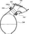
图1a是展示待植入升主动脉中的本发明的管道歧管和血泵组合件的示意性横截面图。 Figure Ia is a schematic cross-sectional view showing the tubing manifold and blood pump assembly of the present invention to be implanted in the ascending aorta. the
图1b是展示在泵运转期间在收缩期时植入升主动脉中的图1a中的管道歧管和血泵组合件的示意图。 Figure Ib is a schematic diagram showing the tubing manifold and blood pump assembly of Figure Ia implanted in the ascending aorta during pump operation at systole. the
图1c是展示在泵运转期间在舒张期时植入升主动脉中的图1a中的管道歧管和血泵 组合件的示意图。 Figure 1c is a schematic diagram showing the tubing manifold and blood pump assembly of Figure 1a implanted in the ascending aorta during pump operation during diastole. the
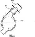
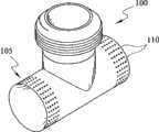
图2a是展示待植入降主动脉中的本发明的管道歧管和血泵组合件的示意性横截面图。 Figure 2a is a schematic cross-sectional view showing the tubing manifold and blood pump assembly of the present invention to be implanted in the descending aorta. the
图2b是展示在泵运转期间在收缩期时植入降主动脉中的图2a中的管道歧管和血泵组合件的示意性横截面图。 Figure 2b is a schematic cross-sectional view showing the tubing manifold and blood pump assembly of Figure 2a implanted in the descending aorta during pump operation at systole. the
图2c是展示在泵运转期间在舒张期时植入降主动脉中的图2a中的管道歧管和血泵组合件的示意性横截面图。 Figure 2c is a schematic cross-sectional view showing the tubing manifold and blood pump assembly of Figure 2a implanted in the descending aorta during pump operation during diastole. the
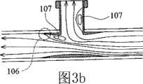
图3a是展示本发明的顺应性匹配管道歧管的示意性横截面图。 Figure 3a is a schematic cross-sectional view showing a compliant-matched conduit manifold of the present invention. the
图3b是展示在泵运转期间在收缩期时图3a中的顺应性匹配管道歧管的血液动力学特征的示意性横截面图。 Figure 3b is a schematic cross-sectional view showing the hemodynamic characteristics of the compliance-matched tubing manifold of Figure 3a during pump operation during systole. the
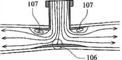
图3c是展示在泵运转期间在舒张期时图3a中的顺应性匹配管道歧管的血液动力学特征的示意性横截面图。 Figure 3c is a schematic cross-sectional view showing the hemodynamic characteristics of the compliance-matched tubing manifold of Figure 3a during pump operation during diastole. the
图4a是展示本发明的类支架管道歧管的示意性透视图。 Figure 4a is a schematic perspective view showing the stent-like conduit manifold of the present invention. the
图4b是展示图4a中的类支架管道歧管的示意性横截面图。 Fig. 4b is a schematic cross-sectional view showing the stent-like conduit manifold in Fig. 4a. the
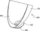
图5a是展示本发明的组织工程化管道歧管的示意性透视图。 Figure 5a is a schematic perspective view showing the tissue engineered tubing manifold of the present invention. the
图5b是展示图5a中的组织工程化管道歧管的示意性横截面图。 Figure 5b is a schematic cross-sectional view showing the tissue engineered tubing manifold in Figure 5a. the
图6是本发明的圆形血泵的示意性横截面图。 Fig. 6 is a schematic cross-sectional view of a circular blood pump of the present invention. the
图7a是本发明的适体血泵的示意图,其中假设外壳的一面是透明的。 Fig. 7a is a schematic diagram of the aptamer blood pump of the present invention, where one side of the housing is assumed to be transparent. the
图7b是不同角度的图7a中的适体血泵的示意图。 Fig. 7b is a schematic view of the aptamer blood pump in Fig. 7a from different angles. the
图8a是组装前的本发明中所用的混流式电动液压驱动器的透视图。 Figure 8a is a perspective view of the mixed flow electrohydraulic driver used in the present invention prior to assembly. the
图8b是组装后的图8a中的混流式电动液压驱动器的横截面图。 Fig. 8b is a cross-sectional view of the assembled mixed-flow electrohydraulic driver of Fig. 8a. the
图9a展示图8a和8b中的混流式电动液压驱动器中的流道,其中所述流道是从血泵到收缩支持囊。 Figure 9a shows the flow path in the mixed flow electrohydraulic driver of Figures 8a and 8b, where the flow path is from the blood pump to the systolic support sac. the
图9b展示图8a和8b中的混流式电动液压驱动器中的流道,其中所述流道是从收缩支持囊到血泵。 Figure 9b shows the flow path in the mixed flow electrohydraulic driver of Figures 8a and 8b, where the flow path is from the systolic support sac to the blood pump. the
图10a是组装前的本发明中所用的离心式电动液压驱动器的透视图。 Figure 10a is a perspective view of the centrifugal electrohydraulic driver used in the present invention prior to assembly. the
图10b是组装后的图10a中的离心式电动液压驱动器的部分横截面图。 Figure 10b is a partial cross-sectional view of the assembled centrifugal electrohydraulic driver of Figure 10a. the
图11a展示图10a和10b中的离心式电动液压驱动器中的流道,其中所述流道是从血泵到收缩支持囊。 Figure 11a shows the flow path in the centrifugal electrohydraulic driver of Figures 10a and 10b, where the flow path is from the blood pump to the systolic support sac. the
图11b展示图10a和10b中的离心式电动液压驱动器中的流道,其中所述流道是从收缩支持囊到血泵。 Figure 11b shows the flow path in the centrifugal electrohydraulic driver of Figures 10a and 10b, where the flow path is from the systolic support sac to the blood pump. the
图12是展示本发明的便携式DPbi-VAD系统布局的示意图。 Fig. 12 is a schematic diagram showing the layout of the portable DPbi-VAD system of the present invention. the
图13是展示图12中的便携式DPbi-VAD系统的细节的示意图。 FIG. 13 is a schematic diagram showing details of the portable DPbi-VAD system in FIG. 12 . the
图14是展示双元脉动控制时程的图,其中AoP:主动脉压,ECG:心电图,T0、T1、T2、T3:连续的时期,Tf、T′f:血泵填充持续时间,且Te:血泵喷射持续时间。 Figure 14 is a graph showing the time course of binary pulse control, where AoP: aortic pressure, ECG: electrocardiogram, T0 , T1 , T2 , T3 : consecutive periods, Tf , T′f : blood pump filling Duration, and Te : blood pump ejection duration.
图15是展示左心室(LV)压力-容积关系对比双元脉动抽汲运转的图。 Figure 15 is a graph showing the left ventricular (LV) pressure-volume relationship versus dual pulsatile pumping operation. the
图16a是展示本发明的收缩支持囊的示意性透视图。 Figure 16a is a schematic perspective view showing a systolic support balloon of the present invention. the
图16b是展示一部分被切除的图16a中的收缩支持囊的示意性透视图。 Figure 16b is a schematic perspective view showing the systolic support balloon of Figure 16a with a portion cut away. the
具体实施方式Detailed ways
包括随附在本说明书后且形成本说明书一部分的图式以描绘本发明的某些方面。本发明和本发明所提供的系统的组件和操作的较清楚概念将通过参考图式中所说明的示范性(且因此非限制性)实施例而变得更显而易见,其中类似参考数字(如果其在一张以上图中出现)表示相同元件。本发明可通过参考这些图式中的一张或一张以上结合本文提供的描述得到更好地理解。 The drawings accompanying and forming a part of this specification are included to depict certain aspects of the invention. A clearer concept of the components and operation of the invention and of the systems provided by the invention will become more apparent by reference to the exemplary (and thus non-limiting) embodiments illustrated in the drawings, in which like reference numerals (if any) appearing in more than one figure) represent the same element. The invention may be better understood by reference to one or more of these drawings in combination with the description provided herein. the
双元脉动设计概念 Dual Pulse Design Concept
整合的顺脉动和反脉动双心室辅助装置的设计提出下列若干新颖设计特点,其将改善同时代的LVAD设计中存在的上述不足。基本上,脉动式抽汲方法的采用是基于两个主要考虑因素,包括:1)与人体生理学相容的植入装置功能;和2)保证长期畅通,以确保患者的手术安全性和生活品质。脉动式循环辅助具有高生理学相容性,且为了不诱发长期并发症,尤其在末梢器官微循环和神经激素调节方面,考虑脉动式循环支持在逻辑上更明智。由于脉动式装置不是强制性的,因此对患者来说当出现意外泵故障时通过其自身自然心脏功能来存活更安全。另外,对于脉动式LVAD来说,较少装置诱发的血液损伤和因此对抗凝疗法的依赖降低或无依赖在显著程度上保证患者手术后的生活品质。 The design of an integrated antegrade and anti-pulse biventricular assist device presents the following several novel design features that would improve the aforementioned deficiencies in contemporary LVAD designs. Basically, the adoption of the pulsatile pumping method is based on two main considerations, including: 1) the function of the implanted device compatible with human physiology; and 2) ensuring long-term patency to ensure the surgical safety and quality of life of the patient . Pulsatile circulatory support is highly physiologically compatible, and it is logically more sensible to consider pulsatile circulatory support in order not to induce long-term complications, especially with regard to peripheral organ microcirculation and neurohormonal regulation. Since the pulsatile device is not mandatory, it is safer for the patient to survive by their own natural heart function in the event of unexpected pump failure. In addition, for pulsatile LVADs, less device-induced blood damage and thus reduced or no reliance on anticoagulant therapy ensures a significant degree of quality of life for patients after surgery. the
根据本发明者的观点,认为连续流动设计的同时转换是使机械挑战造成生理并发症的原因。通常,解决关于LVAD的机械设计困难的适当方法应试图寻找降低尺寸和能量消耗需求的解决方法,而不是将其与极可能诱发出现新的未知且难治的长期并发症的非生理学抽汲交换。 In the view of the present inventors, it is believed that the simultaneous switching of the continuous flow design is what makes the mechanical challenge a physiological complication. In general, an appropriate approach to addressing mechanical design difficulties with LVADs should attempt to find solutions that reduce size and energy expenditure requirements, rather than exchanging them with non-physiological pumping that is likely to induce new unknown and intractable long-term complications . the
已证明反脉动适用于降低患病心脏的收缩期后负荷和增加舒张期冠状动脉灌注。然而,顺脉动心脏压缩可通过右心室和左心室的直接、同步心外膜压缩来帮助心脏收缩。这两个抽汲特征仅可通过使用脉动式装置来实施。对于反脉动或顺脉动循环支持来说,将能量传给血液循环的机械致动的触发器要求相对于自然心律的精确相位控制。迄今为止,已分别提出和设计出利用单独反脉动或顺脉动原理的装置。在单个装置中协作使用反脉动和顺脉动循环支持形成本发明双VAD设计原理的基础。 Counterpulsation has been shown to be useful in reducing systolic afterload and increasing diastolic coronary perfusion in diseased hearts. However, down-pulse cardiac compression assists systole through direct, synchronized epicardial compression of the right and left ventricles. These two pumping features can only be implemented using pulsed devices. For counterpulsatile or propulsatile circulatory support, mechanically actuated triggers that deliver energy to blood circulation require precise phase control relative to natural heart rhythm. To date, devices utilizing the principle of separate anti-pulsation or forward pulsation have been proposed and designed, respectively. The coordinated use of counter-pulsation and forward-pulsation cycle support in a single device forms the basis of the dual VAD design principle of the present invention. the
设想可通过在心脏收缩期间协调顺脉动和反脉动来辅助血液循环的机械装置,其中上游心室收缩力增加,而下游血管后负荷降低,与仅通过上游或下游辅助支持循环的那些装置相比将大大提高所产生的心输出量增加的有效性。在舒张模式中,从主动脉内部执行的反脉动抽汲可类似于常规、良好证明的主动脉内球囊泵(intra-aortic balloon pump;IABP)装置那样辅助冠状动脉灌注。此外,在舒张期期间,所述装置的另一顺脉动功能提供防止患病心脏进一步异常扩张的机械围阻作用。这一在改善心脏血液动力学和心肌收缩和松弛中同时使用顺脉动和反脉动,在本文中称为且将表述为双元脉动心脏辅助,并且给与有助于这种特殊循环支持方式的硬件“双元脉动双心室辅助装置”的名称,缩写为DPbi-VAD。 Mechanistic devices envisaged that could assist circulation by coordinating forward and reverse pulsations during systole, with increased upstream ventricular contractility and decreased downstream vascular afterload, would be less effective than those devices that support circulation only by upstream or downstream assistance. Greatly enhances the effectiveness of the resulting increase in cardiac output. In diastolic mode, counterpulsation pumping performed from inside the aorta can assist coronary artery perfusion similarly to conventional, well-proven intra-aortic balloon pump (IABP) devices. In addition, during diastole, another antegrade function of the device provides a mechanical containment that prevents further abnormal dilation of the diseased heart. This simultaneous use of forward and reverse pulsations in improving cardiac hemodynamics and myocardial contraction and relaxation, is referred to herein and will be expressed as dual pulsation cardiac assist, and gives support to this particular mode of circulatory support The name of the hardware "dual pulsation biventricular assist device", abbreviated as DPbi-VAD. the
双元脉动心脏辅助对脉动式LVAD设计的意义和影响至少存在于三个方面。第一,其降低常规脉动式驱动器设计的能量需求。最初在将工作流体(空气或硅油)从抽汲单元提取回顺应性腔室中时所浪费的反流能量作为用于收缩压缩支持的能量被回收和转化。这种从自然心室的上游和下游末端施加的推拉型操作可大大减低驱动器能量消耗,从而产生任何同时代的脉动式装置无法享有的独特特点。第二,消除对用于容纳顺应性腔室的额外空间的需要。如本发明DPbi-VAD中重新设计的顺应性腔室将最初完全无用的容积储存袋变成功能性收缩压缩支持单元。因此,顺应性腔室不再是脉动式装置不可缺少的负担。省下用于自然心脏执行功能的胸腔现在与顺应性腔室(或收缩支持囊)动态地共用。第三,流入/流出移植物不再是LVAD起作用必须装备的旁路流道。应注意几乎所有过去和同时代的心室辅助装置都需要使用合成移植物,通常是由聚对苯二甲酸乙二酯(涤纶(Dacron))或膨胀聚四氟乙烯(ePTFE)制造的那些移植物,作为用于实施血液从心室/心房排出和用于帮助血液在机械加压后再进入脉管系统床中的管道。临床上,必须在心肺旁路(cardiopulmonary bypass;CPB)支持下进行的移植物套管插入术和吻合术占据大部分手术时间,并且伴有实质围手术期流血和血栓形成危险。统计上观察到,诸如血栓形成、移植物扭折、出血和血管翳增生的许多手术后并发症与这些流入/流出移植物相关。用于帮助反脉动循环支持的本发明单口流入/流出设计使传统移植物吻合术发生巨大变化。本发明DPbi-VAD几乎不需要常规合成移植物且吻合术可通过心脏不停跳手术来进行。引入特别设计的半刚性管道歧管以产生用于血流进入和离开DPbi-VAD的血泵的更短且更流线型的通道。这些上述新颖特征特点改变了脉动式LVAD植入由于需要在拥挤的胸部空间内植入较多且大体积组件而变得比较复杂和困难的总体印象。 The significance and influence of dual pulsatile cardiac assistance on the design of pulsatile LVAD exist in at least three aspects. First, it reduces the energy requirements of conventional pulsed drive designs. Backflow energy originally wasted in extracting the working fluid (air or silicone oil) from the pumping cell back into the compliance chamber is recovered and converted as energy for contracting the compression support. This push-pull operation, applied from the upstream and downstream ends of the native ventricle, greatly reduces driver energy consumption, resulting in unique characteristics not enjoyed by any contemporaneous pulse-based devices. Second, the need for additional space to accommodate the compliance chamber is eliminated. The redesigned compliance chamber as in the present invention DPbi-VAD turns an initially completely useless volume storage bag into a functional collapsible compression support unit. Thus, the compliance chamber is no longer an integral burden on the pulsatile device. The thorax spared for natural cardiac executive functions is now dynamically shared with the compliant chamber (or systolic support sac). Third, the inflow/outflow graft is no longer a bypass channel that must be equipped for the LVAD to function. It should be noted that virtually all past and contemporary ventricular assist devices require the use of synthetic grafts, typically those made from polyethylene terephthalate (Dacron) or expanded polytetrafluoroethylene (ePTFE) , as a conduit for effecting the drainage of blood from the ventricles/atria and for assisting re-entry of blood into the vasculature bed after mechanical pressurization. Clinically, graft cannulation and anastomosis, which must be performed with the support of cardiopulmonary bypass (CPB), occupy most of the operating time and are accompanied by the risk of parenchymal perioperative bleeding and thrombosis. It was statistically observed that many postoperative complications such as thrombosis, graft kink, hemorrhage and pannus hyperplasia were associated with these inflow/outflow grafts. The present invention's single port inflow/outflow design to aid counterpulsatile circulation support is a dramatic change from traditional graft anastomoses. The DPbi-VAD of the present invention requires little conventional synthetic grafts and anastomoses can be performed by beating heart surgery. A specially designed semi-rigid tubing manifold was introduced to create a shorter and more streamlined channel for blood flow into and out of the blood pump of the DPbi-VAD. These aforementioned novel features change the general impression that pulsatile LVAD implantation is complicated and difficult due to the need to implant many and bulky components in a crowded chest space. the
临床上发现几乎30%LVAD受体死于右心衰竭。迄今为止,所开发出可确定LVAD植入的适合性的手术前标记仍令人满意。LVAD受体常常需要植入其他右心室辅助装置 (right ventricular assist device;RVAD)来帮助诱发的右心衰竭。否则,肺部压力将升高且LVAD的填充和因此传递的心输出量提高将由于右心室收缩力不足而减弱。目前提出的DPbi-VAD通过利用对右心室和左心室的直接心脏压缩而完全解决这一问题。在收缩支持囊的顺脉动运转下,肺部和全身循环同时得到帮助。在这种双心室支持期间,在心脏游离壁周围执行的均匀加压防止隔膜移动,这种隔膜移动是长时期对于使用左心室尖端打孔用于血液旁路的所有LVAD植入所观察到的并发症。这种双心室循环支持形成本发明装置的另一重要和独特特点。当植入DPbi-VAD时,相信与传统LVAD植入相关的危险将由于平衡的双心室循环支持而显著降低。 Clinically, almost 30% of LVAD recipients died of right heart failure. To date, the development of preoperative markers to determine suitability for LVAD implantation has been satisfactory. LVAD recipients often require implantation of an additional right ventricular assist device (RVAD) to help with induced right heart failure. Otherwise, pulmonary pressure will rise and filling of the LVAD and thus delivered increase in cardiac output will be diminished due to insufficient right ventricular contractility. The presently proposed DPbi-VAD completely addresses this issue by exploiting direct cardiac compression of the right and left ventricles. Pulmonary and systemic circulation are simultaneously assisted by the pulsatile operation of the systolic support sac. During this biventricular support, the uniform pressurization performed around the free wall of the heart prevents the septal movement that has long been observed for all LVAD implants using left ventricular tip punching for blood bypass complication. This biventricular circulatory support forms another important and unique feature of the device of the present invention. When a DPbi-VAD is implanted, it is believed that the risks associated with conventional LVAD implantation will be significantly reduced due to balanced biventricular circulatory support. the
本发明的创新性DPbi-VAD设计也简化植入程序且大大降低手术危险。在本发明的DPbi-VAD植入程序中可使用心脏不停跳手术。对于DPbi-VAD植入来说,使左心室减负荷以及填充血泵不再需要尖端打孔。连续血流排出和再进入目前通过例如从降主动脉连通的单口管道歧管来促进,使得不需要CPB程序的无损伤心脏VAD植入成为可能。 The innovative DPbi-VAD design of the present invention also simplifies the implantation procedure and greatly reduces surgical risk. Beating heart surgery may be used in the DPbi-VAD implantation procedure of the present invention. For DPbi-VAD implantation, tip punching is no longer required to unload the left ventricle and fill the blood pump. Continuous blood flow egress and re-entry is currently facilitated by, for example, a single-port conduit manifold communicating from the descending aorta, enabling atraumatic cardiac VAD implantation that does not require CPB procedures. the
总之,DPbi-VAD允许实现成对的双元脉动协同作用以补救与脉动式装置相关的传统缺点。有益的IABP产生的反脉动得以保持;然而,由于采用闭塞性、血管内球囊引起的心输出量提高不足的传统IABP缺点通过使用与动脉血管端侧吻合的非闭塞性、主动脉旁血泵来改善。由收缩支持囊提供的直接心脏压缩另外增强心肌收缩力。传统顺应性腔室转化为双心室收缩支持囊不仅解决过度空间需求问题,而且还通过使用其它方面浪费的反流能量来主动加强心室收缩力。平衡的右心和左心支持也自然地实现以避免LVAD诱发的右心衰竭。这种囊还可在治疗上容纳处于舒张期模式的扩张心脏。移植物套管插入术也在本发明DPbi-VAD设计中发生巨大变化。血流的单口流入/流出通道简化手术程序且降低与移植物诱发的并发症相关的死亡率和发病率。在心脏支持中并入双元脉动辅助,预期最初高能量和过度手术空间需求以及脉动式装置的难以植入特征将得到显著改善。在治疗衰竭心脏时,所有治疗性血液动力学和机械功能,即收缩期减负荷、舒张期扩张、心输出量提高和被动机械围阻得以协同整合。最重要的是,DPbi-VAD能够提供所有这些机械治疗性补救,同时使患病心脏保持完整。那些临床和手术优点将启发用于在较低死亡率和发病率情况下用先进MCS衔接治疗心脏衰竭患者的新想法和方案开发。将设定恢复前过渡作为心脏衰竭治疗的主要目的,使移植前过渡和最终疗法作为下一优先考虑的因素。 In summary, DPbi-VAD allows for paired binary pulsatile synergy to remedy the traditional drawbacks associated with pulsatile devices. The beneficial IABP-generated counterpulsation is maintained; however, the disadvantage of traditional IABP due to insufficient enhancement of cardiac output with the use of an occlusive, intravascular balloon is achieved by using a non-occlusive, para-aortic blood pump that anastomoses end-to-side with the arterial vessel to improve. The direct cardiac compression provided by the systolic support sac additionally enhances myocardial contractility. Conversion of a conventionally compliant chamber to a biventricular systolic support sac not only addresses excessive space requirements, but also actively enhances ventricular contractility by using otherwise wasted regurgitant energy. Balanced right and left heart support is also achieved naturally to avoid LVAD-induced right heart failure. Such a balloon can also therapeutically accommodate a dilated heart in diastolic mode. Graft cannulation also undergoes a dramatic change in the present DPbi-VAD design. The single inflow/outflow channel for blood flow simplifies surgical procedures and reduces mortality and morbidity associated with graft-induced complications. The incorporation of dual pulsatile assist in cardiac support is expected to significantly improve the initially high energy and excessive surgical space requirements and difficult-to-implant features of pulsatile devices. When treating the failing heart, all therapeutic hemodynamic and mechanical functions, namely systolic unloading, diastolic dilation, enhancement of cardiac output, and passive mechanical containment are synergistically integrated. Most importantly, DPbi-VAD is able to provide all of these mechanotherapeutic remedies while leaving the diseased heart intact. Those clinical and procedural advantages will inspire the development of new ideas and protocols for treating heart failure patients with advanced MCS engagement with lower mortality and morbidity. Set the transition to recovery as the primary goal of heart failure treatment, making the transition to transplant and final therapy the next priority. the
DPbi-VAD系统描述 DPbi-VAD System Description
DPbi-VAD系统由可具有以下六个模块组成:1)管道歧管;2)血泵;3)体内和/或体外驱动器系统;4)生理学控制器;5)收缩支持囊;和6)能量/信息传送系统。每一模块分别在以下图中展示,阐明设计特点和功能特征的解释以说明其对整个系统所起 的作用和整个系统所需的规格。 The DPbi-VAD system consists of six modules that can have the following: 1) tubing manifold; 2) blood pump; 3) in vivo and/or extracorporeal driver system; 4) physiology controller; 5) systolic support sac; / Information delivery system. Each module is shown separately in the following figures, illustrating the design features and the explanation of functional characteristics to illustrate its contribution to the overall system and the required specifications of the overall system. the
a.管道歧管 a. Pipe manifold
管道歧管构成用于使DPbi-VAD连接于主动脉的合成一体的流入/流出口。这一主动脉旁管道歧管可以是有阀门或无阀门的双向管道。每一选择具有其自身需要实现的设计目标且选择何种类型的歧管更合适取决于临床病症、手术复杂性和医生在植入之前所考虑的判断。图1和2分别展示意欲植入升主动脉或降主动脉中的代表性歧管布置。基本上,通过将两个流向合并在一起来配置所述歧管。尽可能保持流道为流线型以减少动量损失以及减少在血泵的脉动式致动期间湍流的产生。 The tubing manifold constitutes an integrated inflow/outflow port for connecting the DPbi-VAD to the aorta. This para-aortic manifold can be bi-directional with or without valves. Each option has its own design goals that need to be achieved and choosing which type of manifold is more appropriate depends on the clinical condition, surgical complexity, and the physician's judgment considered prior to implantation. Figures 1 and 2 show representative manifold arrangements intended for implantation in the ascending or descending aorta, respectively. Basically, the manifold is configured by combining two flow directions together. The flow path is kept as streamlined as possible to reduce momentum loss and to reduce turbulent flow generation during pulsatile actuation of the blood pump. the
如图1a中所示,以快速连接器204连接于血泵200的上行歧管100A具有用于将血流射入主动脉10中的切向远端流出道101(图1c)和用于填充血泵的弯曲近端管道102(图1b)。这种设计的目的是当血液经过管道时,将常常出现在高速泵喷射期的总压力损失和湍流产生减到最少。远端可无阀门或安装有用来调节血流方向的人工瓣膜103。水母阀由于其成本低、血液动力学性能良好、阀门声音低和通过与管道壁无缝整合所提供的抗血栓性而在本文中得到使用。也可采用机械人工瓣膜或猪人工瓣膜,但其较昂贵。有阀门歧管具有较好泵填充功效且最重要的是其防止在泵填充期期间的大脑血液逆行。当然,除了由于由阀门阻塞引起的较高流动阻力的跨瓣能量损失以外,还有阀门诱发溶血和血栓栓塞的缺点。 As shown in Figure 1a, an ascending
然而,如图2a中所示,下行歧管100是以快速连接器204连接于血泵200的T形管道。在收缩期期间,通过收缩支持囊500在电动液压驱动器300的帮助下提供直接心脏压缩,同时经历通过下行歧管100从主动脉10到血泵200的血泵填充(图2b)。在舒张期期间(图2c),血泵200中的血液通过下行歧管100射入主动脉10中。可改变接点处的交叉角度以得到不同流动阻力,由此使灌注偏移到上游和下游血液循环。类似上行歧管,下行歧管也可有阀门或无阀门。人工瓣膜的安装有助于血泵200更有效提供收缩期减负荷,因为这一降主动脉流的单向流动调节可避免由股循环逆行引起的容积位移。因为管道歧管100和血泵200的降主动脉放置涉及从流入/流出口到主动脉根的较长内腔距离,所以反脉动致动应考虑由主动脉中给予的压力脉冲在其达到主动脉根之前所行进的有限距离引起的相位延迟。下行歧管放置将大脑中风的可能性减到最小,因为当血泵200喷射时,装置诱发的凝块或微栓由于所涉及的较大行进距离和较小对流波速而相对难以向上游对流传递到大脑。 However, as shown in FIG. 2 a , descending
下行无阀门歧管最有吸引力,因为其具有两个主要临床优点。第一,可在心脏不停跳手术之情况下执行下行吻合术。第二,可完全避免人工瓣膜诱发的并发症。因为T形接点流道不具生理性,因此,可能出现促使血栓形成、内膜增生和平滑肌细胞增生的血 管适应不良。为了优化流动和应力状态,提出用于应付这一端侧吻合术的特殊设计。这些提议包括(但不限于)随后的设计选择:1)顺应性匹配歧管、2)类支架歧管和3)组织工程化歧管,如下文所述。 The descending valveless manifold is the most attractive because it has two main clinical advantages. First, descending anastomosis can be performed in the context of beating heart surgery. Second, complications induced by prosthetic valves can be completely avoided. Because the T-junction flow path is not physiological, vascular maladaptation that promotes thrombus formation, intimal hyperplasia, and smooth muscle cell proliferation may occur. In order to optimize the flow and stress state, a special design is proposed to cope with this end-to-side anastomosis. These proposals include (but are not limited to) subsequent design choices: 1) compliance-matched manifolds, 2) stent-like manifolds, and 3) tissue-engineered manifolds, as described below. the
1.顺应性匹配歧管 1. Compliant Matching Manifold
已知顺应性失配是吻合接点处狭窄的主要原因。当经受血压脉动时,移植物末端处的顺应性的跳变导致几何不连续性。几何不连续性引起在移植物/血管接点处产生高壁剪切应力梯度且在紧接下游出现低速环流,从而导致吻合部位附近出现内皮细胞侵蚀和扩散诱发的细胞增殖。顺应性匹配移植物设计的目的是消除移植物/血管接点处的这种顺应性不连续性现象。图3a中展示顺应性匹配歧管设计原理。移植物可由诸如(但不限于)聚氨基甲酸酯的弹性聚合物制造。这种顺应性匹配歧管100具有用于连接于血泵的垂直末端第二路径104,和适合于植入主动脉中(或连通来自人类血管的血液)的水平部分第一路径105。在本文中,第一路径105和第二路径104以一定角度互相交叉。水平部分第一路径105具有向其两个末端逐渐变薄的壁厚度。因为壁顺应性与壁厚度和关于移植物/血管材料的杨氏模数(Young′s modulus)的乘积成反比,所以顺应性匹配移植物原则上应具有尖缘或零厚度的管道末端构型。可将移植物直径设计的比主动脉内腔的直径大一点(0~20%)。当应用插入型吻合术来放置包埋在主动脉内腔中的壁厚度变化的移植物时,可使用缝合方法实现被覆盖的移植物和主动脉的紧密配合以产生整个重叠移植物/血管区中的连续变化顺应性。 Compliance mismatch is known to be a major cause of stenosis at the anastomotic junction. Jumps in compliance at the graft tip cause geometric discontinuities when subjected to blood pressure pulsations. The geometric discontinuity induces high wall shear stress gradients at the graft/vessel junction and low-velocity circulation immediately downstream, resulting in endothelial cell erosion and diffusion-induced cell proliferation near the anastomotic site. The goal of compliance-matched graft design is to eliminate this compliance discontinuity at the graft/vascular junction. The principle of compliance-matched manifold design is shown in Figure 3a. Grafts can be fabricated from elastic polymers such as, but not limited to, polyurethane. This compliant matched manifold 100 has a vertical end
这种顺应性匹配歧管100具有许多血液动力学和生物学优点。平滑和顺应性匹配接面设计将在吻合部位周围出现狭窄和内膜增生的倾向减到最小。可通过平滑、连续变化的复合内腔构型尽可能维持流线型流动模式。所述低湍流管道设计是端侧吻合术可达到的最佳结果。一般来说,在泵填充和喷射期,分别如图3b和3c中所示,在靠近T形接点处出现分离流相关的高压停滞区106以及低速环流区107。这些非生理学流动特征是引起血细胞损伤和病理性血管适应性变化的主要因素。然而,对于本发明歧管设计和吻合术来说,内衬非生物学移植物阻止自然血管受这些异常和混合高剪切力和低速流动特征折磨。值得注意的是这一阻碍作用保护手术创口免受高压作用,由此大大降低围手术期和手术后出血并发症的可能性。除了低顺应性占优势的末端区域,中心管道歧管事实上是半刚性移植物。这种半刚性移植物更有利于帮助反脉动冠状动脉血液灌注。发现舒张期扩张对血管壁弹性敏感。事实上,插入型吻合术用半刚性移植物替代自然血管的一部分。当血泵喷射时,直接由中心半刚性歧管容纳和抵抗最高滞流区域。因此,总体壁顺应性被降低,这因促进舒张期扩张而被认为是受欢迎的。 This compliance matched manifold 100 has many hemodynamic and biological advantages. The smooth and conforming interface design minimizes the tendency for stenosis and intimal hyperplasia around the anastomotic site. Streamlined flow patterns are maintained as much as possible by a smooth, continuously changing composite lumen configuration. The low turbulence tubing design described is the best result achievable for end-to-side anastomosis. In general, during the pump fill and injection phases, as shown in Figures 3b and 3c, respectively, a high
2.类支架歧管 2. Class bracket manifold
管道歧管的另一实施例通过架设歧管移植物的方式来实现。图4a和4b展示这一设计概念的示意图。使用诸如不锈钢、钛或钛合金的生物相容性金属材料建构管道歧管100。在主动脉包埋的管道部分(水平部分第一路径105)上,可分布具有各种形状和孔隙比的洞或孔108以形成穿孔壁109,使得内皮细胞以与带支架血管内观察到的相同的方式迁移。支架孔隙率可变化,其中较高孔隙率(较低模数)区域位于移植物/血管接面周围。尽管目前顺应性匹配与上述顺应性匹配聚合物移植物设计相比相对难以实现,但在植入后某一时期,内皮化将夹在中间且包埋主动脉内腔内的类支架歧管,从而在中心区域产生具有较高刚性的新生内膜复合血管且在末端附近产生较软和较平滑几何/顺应性过渡。对于较大直径(>6~9mm)的动脉来说,由于较高流速作用,再狭窄在临床上极为罕见。通过由移植物结构的支架特征产生的新生内膜层保证抗血栓性。带支架动脉部分的较低顺应性有可能如顺应性匹配歧管般良好增强舒张期扩张。 Another embodiment of the duct manifold is achieved by erecting a manifold graft. Figures 4a and 4b show schematics of this design concept. The
3.组织工程化歧管 3. Tissue Engineering Manifold
组织工程化歧管是顺应性匹配移植物设计的另一变化形式。所用的移植材料可以是先前所提及的那些弹性聚合物。可制造小尺寸(30~300微米)的极小微孔或孔穴110且分布在歧管的水平部分第一路径105上的某些所需内壁或外壁表面区周围(参见图5a和5b)。这些纹理化聚合物表面用作血流中的细胞粘附和生长的托架。锚定的致密血栓块将进一步促使出现血细胞相互作用。含有血小板、单核细胞、巨噬细胞、异物巨细胞、淋巴细胞等的不均质表面将在植入装置后沉积下来。随着时间的过去,由内皮细胞增生的新生内膜将在歧管的纹理化区域中增殖。这些组织工程化新生内膜优选地位于移植物/血管接面处。这可能在较好顺应性匹配、较平滑几何过渡和较强移植物粘附于动脉方面进一步增强接点性能。 Tissue-engineered manifolds are another variation in compliance-matched graft design. The graft materials used may be those elastic polymers mentioned previously. Very small micropores or
b.血泵 b. blood pump
血泵交替地用作接受血液容量的储集器和将储存的血液容量推回动脉的喷射器。如图6中所说明,这一血泵200包含单口设计,其中隔膜弹性膜205分隔血液第一隔室201中的血液和抽汲第二隔室202中的硅工作流体。使用生物相容性材料(例如聚氨基甲酸酯)建构这种血泵。基本形式或圆形几何形状帮助流动冲去作用完全在泵室内完成。然而,流入/流出流出口203可以相对于泵中线的偏心率切向放置以帮助产生旋流。泵的心搏量可在30c.c.到100c.c.或更大的范围内,这取决于所允许的胸部空间和设计驱动器传递的推动力。 The blood pump acts alternately as a reservoir that receives blood volume and as an ejector that pushes the stored blood volume back into the artery. As illustrated in FIG. 6 , this
图7a和7b展示类似于图6中所示的血泵设计的另一变化形式,其中类似部分由相同数字表示。这一血泵200的形状看来像是平坦、弯曲的椭球体。避免凸角以产生流线型外形。通过使其形状轮廓符合内胸廓壁来配置外壳。这种适体设计使得最大限度使用 胸部空间,使得对肺的干扰最小。泵的心搏量可在30c.c.到100c.c.或更大范围内。 Figures 7a and 7b show another variation of a blood pump design similar to that shown in Figure 6, wherein like parts are indicated by the same numerals. The shape of this
在圆形和适体泵设计中,血液和工作流体由弹性膜分隔开。对于图6中所示的圆形血泵来说,弹性膜205具有零应力形状,其几乎与泵壳构型一致。弹性膜205在泵壳的中心内周边周围连接且密封。然而,对于图7a和7b中所示的适体血泵来说,具有与外壳类似但形状较小的弹性膜205,弹性膜205包围形成袋切向连接于流入/流出口203。在两种设计中,硬外壳限制袋的伸展,且因此通过使弹性膜张力较好地限制在疲劳相关阈值以下来延长弹性膜的使用寿命。当圆形泵喷射时,弹性膜205向上移动且刚刚接触壳内表面,使得少量血液储量残留在泵中。在下一泵填充期中,这一残余血液容量将冲走且与新补充的血液混合。至于全容量喷射状态的适体泵,袋完全压缩直至其相对弹性膜可互相接触,在袋中残留第一隔室201的最小残余容量;且当泵填充时,袋恢复其最初零应力、无褶皱完全形状,袋和血泵200的外壳之间形成的第二隔室202的容量减小。然而,对于部分容量喷射来说,储存的血液仍可以完全从泵中射出,尽管需要更多几次搏动。本发明泵设计的无壅滞特征是归因于由壳和弹性膜轮廓提供的涡旋冲洗作用结合不稳定脉动式流动。 In circular and body pump designs, blood and working fluid are separated by an elastic membrane. For the circular blood pump shown in Figure 6, the
排气口开口位于血泵壁中以用于除气。所述位置选择在通过左胸廓切开术植入血泵时收集气泡处的最上区域周围。对于图6中所示的圆形泵来说,排气口开口206位于隔膜弹性膜附接轮缘的附近。然而,对于适体泵来说,如图7a和7b中所示,排气口开口206位于容纳袋附接和固定短柱的袋的底部。 A vent opening is located in the blood pump wall for degassing. The location was chosen around the uppermost area where air bubbles were collected when the blood pump was implanted through a left thoracotomy. For the round pump shown in Figure 6, the
如图6、7a和7b中所示,血泵的上端具有安装在喉部周围的快速连接器204以使得泵200与管道歧管方便的快速组装或脱离。使用硅垫圈能够紧密整合血泵与歧管。然而,在底部端,泵壳汇集成圆管208以使得连接于驱动器。对于有效泵/驱动器安装采用类似管道歧管/血泵整合所用的类似快速连接器设计。可通过使用体内或体外驱动器系统实现使硅油流入血泵和从血泵中流出往复移动。另一排气口开口207建在泵外壳上以在组装血泵以及驱动器时辅助除气。 As shown in Figures 6, 7a and 7b, the upper end of the blood pump has a
c.体内和体外驱动器系统 c. In vivo and in vitro driver systems
1.体内驱动器系统 1. Internal driver system
本发明的体内驱动器设计采用液压抽汲原理。除叶轮和转换阀外,所设计的电动液压(electro-hydraulic;EH)驱动器由两个电驱动直流电(direct current;DC)无刷电动机组成,一个用于产生转矩且另一个用于调节流动方向。使用加压的液压流体或硅油使得能够在几乎不对致动机构的位置和定向进行限制的情况下布署动力。本发明EH驱动器通过参考心电图(electrocardiogram;ECG)波形不同步致动血泵和收缩支持囊。使用加压液压工作流体流经的插管进行动力传输。快速连接器使得能够在EH驱动器主体连接 于血泵和/或收缩支持囊时对其进行快速且方便的组装/脱离和调整定向。 The in vivo actuator design of the present invention uses the hydraulic pumping principle. In addition to the impeller and switching valve, the designed electro-hydraulic (EH) actuator consists of two electrically driven direct current (DC) brushless motors, one for generating torque and the other for regulating flow direction. The use of pressurized hydraulic fluid or silicone oil enables power to be deployed with few constraints on the position and orientation of the actuation mechanism. The EH driver of the present invention actuates the blood pump and the systolic support sac asynchronously by reference to the electrocardiogram (ECG) waveform. Power transmission is performed using a cannula through which pressurized hydraulic working fluid flows. The quick connector enables quick and easy assembly/disassembly and reorientation of the EH driver body when it is attached to the blood pump and/or systolic support balloon. the
对于脉动式流动抽汲来说,单独寻找叶轮的最佳设计点既不关键,也不实际,因为在泵运转期间,在泵性能图上展示环,而不是固定点。常常应寻找跨越某一运转环范围的总高效率平台期。为了使植入简易,从事微型LVAD设计多半需要更优先考虑的设计标准解剖学或空间考虑因素,使得高运转液压效率成为需要实现的下一目的。 Finding the optimum design point for the impeller alone is neither critical nor practical for pulsating flow pumping, since loops are shown on the pump performance graph during pump operation, rather than fixed points. Always look for an overall high efficiency plateau across a range of operating cycles. Engaging in miniaturized LVAD design likely requires more prioritizing design criteria anatomical or space considerations for ease of implantation, making high operating hydraulic efficiency the next goal to be achieved. the
在本发明DPbi-VAD驱动器设计中,使两个DC无刷电动机浸没于EH驱动器中所含的硅油浴中。所产生的热量主要来自运转不良的卷杆和电子控制器。油流的晃动可用作将散失热对流传递和再分布到包括外壳、插管和与循环血流接触的隔膜弹性膜的整个DPbi-VAD的表面的有效冷却机制。因此,热量可通过传导到VAD植入物周围的组织来局部转移或通过在整个人类循环系统中对流传递到整个身体来全面转移。在本发明电动液压设计中几乎不产生发热点,这是增加电子仪器的可靠性和由此延长DPbi-VAD在运转中的使用寿命的重要因素。 In the present DPbi-VAD driver design, two DC brushless motors are submerged in a silicone oil bath contained in the EH driver. The heat generated is mainly from the poorly functioning reel rods and electronic controls. The sloshing of the oil flow can be used as an effective cooling mechanism to convectively transfer and redistribute lost heat to the surface of the entire DPbi-VAD including the housing, cannula, and diaphragm elastic membrane in contact with circulating blood flow. Thus, heat can be transferred locally by conduction to the tissues surrounding the VAD implant or globally by convection throughout the body throughout the human circulatory system. Few hot spots are created in the electrohydraulic design of the present invention, which is an important factor in increasing the reliability of the electronics and thus prolonging the service life of the DPbi-VAD in operation. the
存在两种电动液压驱动器设计,其在下文中呈示。一种使用混流式且另一种使用离心式叶轮设计,分别取决于所强调的效率或扬程(head-rise)的着重点。 There are two electrohydraulic driver designs, which are presented below. One uses a mixed-flow and the other uses a centrifugal impeller design, depending on the emphasis on efficiency or head-rise, respectively. the
1.1混流式驱动器 1.1 mixed flow driver
根据本发明的一个优选实施例建构的混流式电动液压驱动器在图8a和8b中展示,其组装有流动元件/部件: A mixed flow electrohydraulic driver constructed in accordance with a preferred embodiment of the present invention is shown in Figures 8a and 8b, assembled with flow elements/components:
301 驱动器外壳, 301 drive housing,
302 基底帽, 302 base cap,
303 轴承, 303 bearings,
304 锁环, 304 lock ring,
305 转矩电动机外壳, 305 torque motor housing,
306 转矩电动机定子, 306 torque motor stator,
307 转矩电动机转子, 307 torque motor rotor,
308 轴承, 308 bearings,
309 锁环, 309 lock ring,
310 转换阀主体, 310 diverter valve body,
311 轴承, 311 bearings,
312 转换阀头部, 312 diverter valve head,
313 转换阀流出管道, 313 changeover valve outflow piping,
314 步进电动机转子, 314 stepper motor rotor,
315 步进电动机定子, 315 stepper motor stator,
316 转换阀流入管道, 316 changeover valve inflow pipeline,
317 轴承,和 317 bearings, and
318 混流式叶轮。 318 Mixed flow impeller. the
叶轮318容纳于由互相不可旋转地啮合的转换阀流出管道313和转换阀流入管道316形成的内转换阀中,且所述内转换阀可旋转地安置于由转换阀主体310和转换阀头部312形成的固定外壳中。由电动机外壳305、电动机定子306和电动机转子307形成的DC无刷转矩电动机以5,000-12,000转/分钟(rounds per minute;RPM)的典型速度范围驱动这一混流式叶轮318。应抵抗主动脉部位处的120mmHg压力升高来传递约11,000RPM、至少20公升/分钟(liter/min;LPM)流流率。通过使用计算流体动力学(computational fluid dynamics;CFD)分析来设计和优化叶轮。由电动机转子314和电动机定子315形成的步进电动机安装在转换阀(313、316)的腰部周围。这一步进电动机(314、315)可使分别钻于固定外壳(310、312)和内旋转转换阀(313、316)的两侧壁上的流入/流出孔对一起对准。通过控制器,使用ECG波形作为进行反脉动抽汲的参考来调节步进运动。两种电动机都单向转动以便将由逆转方向引起的能量消耗减到最少。如通过转换阀运动所确定的两种流道路径将引导加压油通过驱动器外壳301上形成的流入/流出口320和流出/流入口319在血泵与收缩支持囊之间来回流动。如图2b和2c中所示,血泵200通过插管321连接于驱动器300,且收缩支持囊500通过另一插管322连接于驱动器300。这种整合的驱动器和流道系统在图9a和图9b中展示。应注意所有电组件和机械组件都浸没于油室中。可实现优良冷却和润滑以维持这一EH驱动器的长期畅通。 The
离心式驱动器 centrifugal drive
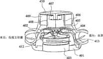
根据本发明的一个优选实施例建构的使用离心式叶轮抽汲硅油的电动液压驱动器在图10a和10b中展示,其组装有流动元件/部件: An electrohydraulic driver using a centrifugal impeller to pump silicone oil constructed in accordance with a preferred embodiment of the present invention is shown in Figures 10a and 10b, assembled with flow elements/parts:
401 驱动器外壳, 401 drive housing,
402 圆顶阀, 402 dome valve,
403 转矩电动机, 403 torque motor,
404 离心式叶轮, 404 centrifugal impeller,
405 圆顶阀头部, 405 dome valve head,
406 转换连接器, 406 conversion connector,
407 轴承, 407 bearings,
408 步进电动机转子, 408 stepper motor rotor,
409 步进电动机定子,和 409 stepper motor stator, and
410 驱动器头部。 410 drive head. the
通过这种离心式驱动器使油在收缩支持囊与血泵之间往复移动的流道在图11a和11b中说明。叶轮404也使用由机构内部设计优化程序辅助的先进CFD套件来设计。适当地选择径向叶轮的入口和出口直径和流入和流出平面处的叶片高度以达到跨越宽运转速度范围的高泵效率。本发明的离心式EH驱动器的设计目标设定为抵抗200mmHg的压力梯度以约4000到8000RPM的转速传递容量流流率(>20LPM)。可使用金属或陶瓷滚珠轴承来支撑也是DC无刷转矩电动机403的转子轴的动力传输轴。可使用内旋转和外旋转转子设计。因为硅油可净化轴承内所产生的热量和碎屑,因此可保证本发明EH驱动器的较长使用寿命。 The flow path through which this centrifugal drive reciprocates oil between the systolic support sac and the blood pump is illustrated in Figures 11a and 11b. The
由圆顶阀402和圆顶阀头部405形成的钟形转换阀调节流动和液压动力传输方向。这种钟形转换阀由容纳步进电动机转子408和步进电动机定子409的DC无刷步进电动机来驱动。在圆顶阀402的上端周围和在圆顶阀头部405与转换连接器406之间形成圆周形窗口。在钟形转换阀与EH驱动器的驱动器外壳401之间形成的间隙和凹槽形成用于硅油流进入叶轮入口的环形通道。来自收缩囊或离开血泵的入流在环形间隙周围流通,向上爬且通过圆顶的开口窗进入并且最后进入叶轮入孔中。 A bell-shaped switching valve formed by
然而,通过外壁是圆顶阀402的螺旋形小室412收集叶轮加压油。孔413开口于螺旋形小室壁上,其在旋转且与两个分别连接于血泵或收缩囊的侧插管交替地对准时完成动力布署任务。一对分别从EH驱动器外壳401的左侧和右侧突出的“V型”臂414和415形成用于使工作流体在血泵与收缩支持囊之间来回往复移动的流入/流出道。EH驱动器可视作交替地晃动其两个末端之间的油流的加压单元,一个末端为低压心室侧(~0mmHg)且另一个末端为高压(80-120mmHg)主动脉侧。在抽汲血泵时,对螺旋形小室指定优选高效流出道角度。由于在螺旋形小室出口处流出道的急转弯,在油流从血泵退回期间,产生额外损失。然而,这一损失将通过使油从血泵穿梭回来以压缩心室时主动脉的较高前负荷状态来补偿。 However, impeller pressurized oil is collected through a
2.体外驱动器系统 2. In vitro drive system
体外驱动器系统可以是床边或便携式单元。在医院的重病监护室(intensive care unit;ICU)中主要使用床边模式。然而,便携式模式设计用于植入DPbi-VAD后出院且离开手术后护理期时的门诊病人。 An extracorporeal driver system can be a bedside or portable unit. The bedside mode is mainly used in the intensive care unit (ICU) of the hospital. However, the portable model is designed for outpatient use after implantation of the DPbi-VAD and upon discharge from the postoperative care period. the
如下文所述,体外驱动器系统可通过气压或混合气压/电动液压动力源来推动。为了将由经皮驱动管线引起的感染可能性减到最小,采用类似IABP所使用的那些薄气动管线。基本上,对于所有下文所述的体外系统来说,分别与植入物(即血泵和收缩支持囊)连接的胸内流体动力致动管线是薄气压管,其中流动诸如氦的惰性、低分子量气体。在 每一胸内气压驱动管线的出口处,将皮肤钮状物植入皮肤下,使得内气压驱动管线与外部动力源系统可方便的快速连接/断开。 As described below, the extracorporeal driver system can be propelled by pneumatic or hybrid pneumatic/electrohydraulic power sources. To minimize the possibility of infection from percutaneous drive lines, thin pneumatic lines like those used by the IABP are employed. Basically, for all extracorporeal systems described below, the intrathoracic hydrodynamic actuation lines connected to the implants (i.e. blood pump and systolic support balloon) respectively are thin gas tubes through which flow an inert, low molecular weight gas. At the outlet of each intrathoracic air pressure driving line, a skin button is implanted under the skin, so that the internal air pressure driving line can be quickly connected/disconnected with the external power source system. the
对于所有体外驱动器来说,胸内动力传输设计是相同的。通过插上/拔下连接于床边控制台或便携式DPbi-VAD驱动单元的外部驱动线,植入本发明胸内装置的患者可以卧床或走动,这取决于患者具有的医学治疗和生活方式。 The intrathoracic power transmission design is the same for all extracorporeal drivers. By plugging/unplugging the external drive wire connected to the bedside console or the portable DPbi-VAD drive unit, the patient implanted with the intrathoracic device of the present invention can be bedridden or ambulatory, depending on the medical treatment and lifestyle the patient has. the
2.1床边驱动器系统 2.1 Bedside driver system
因为本发明DPbi-VAD使用与IABP相同的操作原理,所以IABP驱动器控制台可用作抽汲DPbi-VAD的驱动器系统。可设计转接器来连接DPbi-VAD与IABP控制台,根据DPbi-VAD操作要求调整气压容量和抽汲压力。一般来说,需要不同步致动血泵和收缩支持囊的两个IABP驱动器来驱动DPbi-VAD系统。也可以为在某些临床状态下仅需要一个循环支持方式的患者选择反脉动和顺脉动的分开应用。 Since the DPbi-VAD of the present invention uses the same operating principle as the IABP, the IABP driver console can be used as a driver system for pumping the DPbi-VAD. An adapter can be designed to connect DPbi-VAD and IABP console, and adjust the air volume and pumping pressure according to the operation requirements of DPbi-VAD. In general, two IABP drivers that asynchronously actuate the blood pump and the systolic support sac are required to drive the DPbi-VAD system. Separate application of counterpulsation and antegrade pulsation may also be selected for patients who require only one modality of circulatory support in certain clinical situations. the
使用指定驱动器系统实现床边DPbi-VAD的另一实施例。这种床边驱动器几乎与来源于下文所说明的便携式DPbi-VAD驱动器的设备相同。仅有的差别在于:第一,除电池供应的直流电外,电力供应模块允许从插座接受交流电;和第二,为医务人员准备更精密的监测/显示/调整系统以用于参考和控制。 Another embodiment of the bedside DPbi-VAD is implemented using a designated driver system. This bedside drive is nearly identical to the device derived from the portable DPbi-VAD drive described below. The only differences are: first, the power supply module allows receiving AC power from the socket in addition to the DC power supplied by the battery; and second, a more sophisticated monitoring/display/adjustment system is prepared for the medical staff for reference and control. the
2.2便携式驱动器系统 2.2 Portable drive system
便携式驱动器是为离开ICU阶段的患者设计的。本发明便的携式系统是先前所述的体内驱动器的变化形式。图12和13说明如何建构这种混合气压/电动液压驱动器系统的想法。事实上,这种系统是通过放宽空间/解剖学限制而从体内EH驱动器衍生出。可改良叶轮尺寸和转矩电动机的转速以解决与体外系统相关的较长流体路径中所产生的损失。螺旋形小室流入/流出道切向对准于螺旋形小室主体,所以消除流体路径中的急转弯以实现较好液压效率。现在两个储集器323和324连接于流入/流出插管321和322以替代设计用于体内系统的原来的血泵200和收缩支持囊500。每一储集器由隔膜弹性膜325和326的层分成两个分别由硅油和氦气填充的分区。在每一储集器的近氦分区侧,气压管线327(328)离开且通过特别设计的抗感染皮肤钮状物329(330)连接于胸内单元。当运转时,叶轮驱动的往复移动硅油将在两个相邻储集器323和324上形成压缩和真空动力,由此驱动氦气且使得植入患者胸腔中的血泵200和收缩支持囊500同时致动。 The portable drive is designed for patients leaving the ICU stage. The portable system of the present invention is a variation of the previously described internal drive. Figures 12 and 13 illustrate the idea of how to build this hybrid pneumatic/electrohydraulic drive system. Indeed, such a system is derived from in vivo EH drives by relaxing the spatial/anatomical constraints. The impeller size and rotational speed of the torque motor can be modified to account for losses incurred in the longer fluid paths associated with extracorporeal systems. The helical chamber inflow/outflow channels are tangentially aligned with the helical chamber body, so sharp turns in the fluid path are eliminated for better hydraulic efficiency. Two reservoirs 323 and 324 are now connected to the inflow/
可使用多种混合驱动器执行多重冗余。使用平行排列的两个驱动单元EDH1和EDH2的双重冗余在图13中举例说明。当检测出泵故障时,电子控制器600将立即发送指令信号以启动备用驱动器且由此可保证不停止、连续驱动。控制阀601、602安装在流体路径的接头处以调节致动流体方向。也可使用控制器中程式化的控制逻辑设计两个EH驱动器的交替性、间歇性运转。通过对每一EH驱动器交替提供适当闲置时间, 可实现便携式驱动器系统的总体延长的使用寿命。 Multiple redundancy can be implemented using a variety of hybrid drives. Double redundancy using two drive units EDH1 and EDH2 arranged in parallel is illustrated in FIG. 13 . When a pump failure is detected, the electronic controller 600 will immediately send a command signal to start the backup drive and thus ensure non-stop, continuous drive. Control valves 601, 602 are installed at the joints of the fluid paths to regulate the direction of the actuation fluid. Alternate, intermittent operation of the two EH drives can also be designed using the programmed control logic in the controller. By alternately providing appropriate idle times for each EH drive, an overall extended useful life of the portable drive system can be achieved. the
每一储集器323(324)具有连接于氦补充系统700的气压管线。可选择适当氦容量来治疗临床上遇到的不同心脏衰竭综合症。补充程序类似于用IABP系统所实施的那些程序。重新连接体外气压管线327和328与体内气压管线331和332后,首先必须完全排出氦容量且接着补充至所需容量。 Each reservoir 323 ( 324 ) has an air pressure line connected to the helium replenishment system 700 . Appropriate helium volumes can be selected to treat different heart failure syndromes encountered clinically. Supplementary procedures are similar to those implemented with the IABP system. After reconnecting the extracorporeal air pressure lines 327 and 328 and the intracorporeal air pressure lines 331 and 332, the helium volume must first be fully vented and then replenished to the required volume. the
与使用大体积和重往复式发动机和贮罐的同时代的气压驱动器系统相比,本发明的涡轮机械系统重量更轻且更安静。将诸如电池组603、电子控制器600和混合气压/电动液压单元800的子系统整合到箱形罐中,其可容易地由患者使用可穿戴外套来携带,如图12中所描绘。具有必须植入人体内的最小模块的VAD系统始终受到欢迎。对于本发明便携式DPbi-VAD来说,复杂电动机械和动力供应/控制模块全部都放置于体外。不仅可允许对驱动器和控制器进行定期检查和维修,在运转期间由驱动器所产生的热量也可容易地排放到大气中。万一出现紧急机器故障,也可进行故障单元的快速替换。因此通过这种便携式驱动器系统保证了良好移动性和安全性运转。因为血泵和收缩支持囊的脉动式运转不具强制性,所以可允许DPbi-VAD停止一定时间(本质上是几分钟到零点几小时)。这将进一步为患者因日常事件穿上/脱下DPbi-VAD外套提供方便和自由,诸如在实际生活中常常发生的换衣服和/或洗澡。 The turbomechanical system of the present invention is lighter weight and quieter than contemporary pneumatic drive systems using large and heavy reciprocating motors and storage tanks. Subsystems such as battery pack 603, electronic controller 600, and hybrid pneumatic/
d.生理学控制器 d. Physiological controller
本发明控制器设计的目的在于形成用于EH驱动器的预定时间选择和施压水平控制。收缩期减负荷、舒张期扩张和心外膜压缩的成功执行需要与心脏律动有关的精确阶段性操作。收缩期减负荷和心外膜压缩以单一致动对形式执行且起动最好设在心室正准备收缩的时候。然而,舒张期扩张在心脏舒张期期间在主动脉瓣正关闭(从主动脉压迹线的重搏切迹开始)且冠状动脉壁开始放松时起动。所有这些致动控制需要使用ECG或主动脉压波形作为参考基准。假如对于抽汲控制采用ECG信号,那么必须发展从ECG信号迹线上的其他波特征中识别出R波的算法。如果选择主动脉压作为传感器信号,那么可容易地发展类似波形识别方法。 The purpose of the controller design of the present invention is to create a predetermined timing and pressure level control for the EH drive. Successful execution of systolic unloading, diastolic expansion, and epicardial compression requires precise phasic manipulation in relation to cardiac rhythm. Systolic unloading and epicardial compression are performed as a single actuation pair and initiation is best when the ventricle is preparing to contract. However, diastolic dilation is initiated during diastole when the aortic valve is closing (starting from the dicrotic notch of the aortic pressure trace) and the coronary artery walls begin to relax. All of these actuation controls require the use of the ECG or aortic pressure waveform as a reference. If an ECG signal is used for pumping control, an algorithm must be developed to identify the R-wave from other wave features on the ECG signal trace. If aortic pressure is chosen as the sensor signal, a similar waveform recognition method can be easily developed. the
心输出量可视为心搏量乘以心率的乘积。生理学心脏调节是通过由神经和激素控制自主地调整心搏量和心率来实现的。通常较高的心率对应于较大心肌收缩力且因此对应于高心搏量。因此,模拟自然心脏调节的生理学控制器可单独基于心率来构造,使得ECG信号成为唯一所需的控制输入。因为R波有迹线,所以可确定EH驱动器的抽汲频率,其可与所检测到的心率一致或成比例。这一特征使得本发明装置可回应生理学循环需要来运转。应注意当通过更快转换阀孔交叉完成许多频繁电动液压抽汲喷射时,孔的交叉流动阻力将相应增加。因此,应提高叶轮传递的液压以克服孔损失和所需的较高喷 射惯性。因此,应使用适当控制逻辑协调步进电动机和转矩电动机的速度控制,从而产生在生理学上执行循环辅助以符合心输出量要求以及治疗性目的的情况。在心律不整的情况下,则将不管无节律的ECG信号而规定固定抽汲频率的默认抽汲情景设置。 Cardiac output can be thought of as the product of stroke volume times heart rate. Physiological cardiac regulation is achieved through the automatic adjustment of stroke volume and heart rate by neural and hormonal control. Generally a higher heart rate corresponds to greater myocardial contractility and thus a high stroke volume. Thus, a physiological controller that mimics natural cardiac regulation can be constructed based solely on heart rate, making the ECG signal the only required control input. Because the R-wave has a trace, the pumping frequency of the EH driver can be determined, which can be coincident or proportional to the detected heart rate. This feature allows the device of the present invention to operate in response to physiological cyclic demands. It should be noted that as many frequent electro-hydraulic swab injections are done with faster switching valve orifice crossings, the orifice crossing flow resistance will increase accordingly. Therefore, the hydraulic pressure delivered by the impeller should be increased to overcome the orifice losses and the required higher jet inertia. Therefore, appropriate control logic should be used to coordinate the speed control of the stepper and torque motors to create a situation where circulatory assistance is performed physiologically to meet cardiac output requirements as well as therapeutic purposes. In the case of arrhythmia, then the default pumping scenario setting will dictate a fixed pumping frequency regardless of the arrhythmic ECG signal. the
本发明控制器的致动器系统由两个电动机组成,其分别驱动用于控制频率或心率的转换(或圆顶)阀和用于调节机械动力传递的叶轮。因为混流式和离心式EH驱动器在控制器发展的意义上相似,所以我们在下文仅说明离心泵的控制设计。可通过所涉及参数的小调整来实现混流泵的等效控制设计。 The actuator system of the controller of the present invention consists of two electric motors which respectively drive a switching (or dome) valve for controlling frequency or heart rate and an impeller for regulating mechanical power transmission. Because mixed-flow and centrifugal EH drives are similar in the sense of controller development, we only illustrate the control design for centrifugal pumps below. An equivalent control design for a mixed flow pump can be achieved with small adjustments of the parameters involved. the
对于离心式EH驱动器来说,步进电动机安装于圆顶阀头部上以用于控制位置和移动。在控制油流方向时,步进电动机连续地或间歇地并且单向地转动。在每次心跳时,抽汲控制可分为两个阶段。第一是主动脉侧的收缩期减负荷控制和自发地心室侧的心外膜压缩。第二是舒张期扩张控制,同时收缩支持囊起类似从动油袋的作用。对于收缩期和舒张期致动来说,每一抽汲控制基本上由三个步骤组成,开始是起动控制且接着是位置和持续时间控制。起动控制决定何时开始控制动作。位置控制驱动圆顶孔与流入/流出口对准。然而,持续时间控制确定完成孔对准后泵喷射应持续多长时间。使用先前检测到的时间作为确定控制算法的基础,所有这些六个控制步骤都在一个心跳循环中完成。图14结合连续心脏循环中的血液动力学、阀运动和心动图说明控制时程。如图15中所示,将这些控制致动的时间选择和时段进一步转换成左心室的压力-容积关系。 For centrifugal EH drives, stepper motors are mounted on the dome valve head for position and movement control. The stepper motor rotates continuously or intermittently and unidirectionally while controlling the direction of oil flow. At each heartbeat, the pumping control can be divided into two phases. The first is controlled systolic unloading on the aortic side and spontaneous epicardial compression on the ventricular side. The second is diastolic dilation control, while the systolic support sac acts like a slave oil bag. For systolic and diastolic actuation, each pumping control essentially consists of three steps, starting with an actuation control followed by a position and duration control. Start control determines when the control action starts. The position control drives the alignment of the dome hole with the inflow/outflow port. However, the duration control determines how long the pump spray should last after hole alignment is complete. Using the previously detected time as the basis for determining the control algorithm, all these six control steps are done in one heartbeat cycle. Figure 14 illustrates the control time course in conjunction with hemodynamics, valve motion, and cardiograms in continuous cardiac cycles. As shown in Figure 15, the timing and period of these control actuations are further translated into pressure-volume relationships of the left ventricle. the
在图14上存在展示说明本发明控制算法的四个连续心脏循环。默认位置是叶轮螺旋形小室孔与导向收缩支持囊的流入口/插管对准的位置。这也是确定参考零度角度和每次转动后重置的位置。在0循环时,尽管起动控制但转换阀位于默认零度位置。驱动器仍迎合定向用于收缩期减负荷的抽汲方向。当检测到两个连续R波时,计算出循环周期T0且相应确定与T0成比例的两个时间间隔Tf和Te。最初在控制逻辑中预置确定Tf和Te相对于可得到的循环周期T0的比例的一对参数。舒张期扩张在第一消逝时间间隔Tf结束时开始。此时,位置控制将快速移动且使圆顶阀孔与血泵的流出口/插管对准。接着执行舒张期扩张直至Te间隔结束。完成舒张期扩张后,致动步进电动机以继续旋转和使阀孔重新定位为与收缩支持囊的流入口/插管对准。完成孔对准后立即激活收缩期减负荷。大概说来,残余持续时间将占据下一R波开始之前的剩余抽汲循环。这意味着在心脏收缩之前主动脉压已下降。当检测到新的R波时,可得到更新的循环周期T1且重新计算以下两个时间间隔Tf和Te。这种循环控制指令顺序将循环地产生且在连续地检测到新R波的情况下执行。 On Figure 14 there are four consecutive heart cycles shown illustrating the control algorithm of the present invention. The default position is where the impeller helical chamber hole is aligned with the inflow port/cannula leading to the systolic support sac. This is also where the reference zero degree angle is determined and reset after each turn. At 0 cycles, the diverter valve is at the default zero degree position despite the control being activated. The driver still caters to the direction of the swab directed for systolic unloading. When two consecutive R-waves are detected, the cycle period T0 is calculated and the two time intervals Tf and Te proportional to T0 are determined accordingly. A pair of parameters determining the ratio of Tf andTe relative to the available cycle period T0 is initially preset in the control logic. Diastolic expansion begins at the end of the first elapsed time intervalTf . At this point, the position control will snap and align the dome valve aperture with the outflow port/cannula of the blood pump. Diastolic expansion is then performed until the end of theTe interval. After diastolic expansion is complete, the stepper motor is actuated to continue rotation and reposition the valve orifice into alignment with the inflow port/cannula of the systolic support balloon. Systolic unloading is activated immediately after hole alignment is complete. Roughly speaking, the residual duration will account for the remaining pump cycle before the next R-wave begins. This means that the pressure in the aorta has dropped before the heart contracts. When a new R-wave is detected, an updated cycle period T1 is available and the following two time intervals Tf andTe are recalculated. This sequence of cyclic control instructions will be generated cyclically and executed if new R-waves are continuously detected.
光电检测器传感器对安装于圆顶阀和驱动器外壳上以在循环中完成一个360度转动时帮助重定位圆顶阀的默认位置。在每一循环中零度参考位置重新确定为光电检测器对 对准到一起。在本发明设计中,零角度位置设定在对准孔以执行收缩期减负荷的位置。这种重定位控制可防止角度偏移积累且确保每一跳动时螺旋形小室孔将正确地与流出道对准。 A photodetector sensor pair is mounted on the dome valve and actuator housing to help reposition the dome valve to its default position as it completes one 360 degree turn in the cycle. The zero degree reference position is re-established on each cycle as the photodetector pairs are aligned together. In the present design, the zero angle position is set at the position where the bore is aligned to perform systolic unloading. This repositioning control prevents angular offset build-up and ensures that the helical cell holes will be properly aligned with the outflow tract with every beat. the
由于较大通流孔对应于较低喷射损失,所以控制逻辑应在步进电动机的动力限度下选择,以尽可能快地使旋转加速度达到最大以使圆顶阀孔定位为与右流出道或左流出道对准。可调整收缩期/舒张期比率以得到最优舒张期扩张以及对系统循环的辅助。在心律不整或心率大于某一限度(即每分钟100跳)的情况下,控制器将忽略心动图且产生固定速率或降低1到2或1到3跳的脉动指令以得到与由IABP控制逻辑提供的那些相同的最优心脏支持。 Since larger orifices correspond to lower injection losses, the control logic should be selected within the power limits of the stepper motor to maximize rotational acceleration as quickly as possible to position the dome valve orifice with either the right or left orifice. Outflow tract alignment. The systolic/diastolic ratio can be adjusted for optimal diastolic expansion and assistance to systemic circulation. In case of arrhythmia or heart rate greater than a certain limit (i.e. 100 beats per minute), the controller will ignore the cardiogram and generate a pulsatile command at a fixed rate or decrease by 1 to 2 or 1 to 3 beats to obtain the same as controlled by the IABP logic Offers the same optimal cardiac support as those offered. the
DC无刷转矩电动机对叶轮提供主要驱动力。动力由电池组供应且由速度控制器调节。预期这一转矩电动机传递在20到30瓦特范围内的动力输出。当心率增加时,孔阻力和动脉压都升高,从而需要更大抽汲力来实现所需心输出量要求。可采用被动或主动转矩电动机控制以应付这种生理学需要。举例来说,可关于心跳范围设定预定分段RPM目标时程以进行被动控制,在电动机驱动时实施自主RPM跟踪控制。也可考虑精密主动生理学控制,其需要提供更多传感器或资讯以反映身体的需求或心脏功能应该具有的调节规律。 A DC brushless torque motor provides the primary drive for the impeller. Power is supplied by a battery pack and regulated by a speed controller. This torque motor is expected to deliver a power output in the range of 20 to 30 watts. As heart rate increases, both orifice resistance and arterial pressure increase, requiring greater pumping force to achieve the desired cardiac output requirement. Passive or active torque motor control can be employed to address this physiological need. For example, a predetermined segmented RPM target schedule can be set with respect to heartbeat range for passive control, while autonomous RPM tracking control is implemented when the motor is driven. Sophisticated active physiological control can also be considered, which needs to provide more sensors or information to reflect the needs of the body or the regulation rules that the heart function should have. the
e.收缩支持囊 e. Shrink support capsule
双心室收缩期压缩与反脉动循环辅助的整合是本发明的独特特点。最初,对于脉动式LVAD装置来说,顺应性腔室的需要已是必然倾向,因为脉动需要额外容量来经受心搏量的来回位移。因此,加倍植入装置所需的空间。收缩支持囊的实施将这一缺点变成优点。当囊膨胀时,心室收缩,且反之囊缩小。因此,容纳这一囊的空间并不占据过多额外空间,因为其与自然心室动态地共用所述空间。 The integration of biventricular systolic compression and reverse pulsatile circulation assistance is a unique feature of the present invention. Initially, the need for a compliant chamber was inevitable for pulsatile LVAD devices, since the pulsation required additional volume to withstand stroke volume back and forth. Thus, the space required to implant the device is doubled. The implementation of the systolic support capsule turns this disadvantage into an advantage. When the sac expands, the ventricles contract, and vice versa the sac contracts. Therefore, the space to house this sac does not take up much extra space, since it dynamically shares that space with the native ventricle. the
根据优选实施例,本发明收缩支持囊由两片聚氨基甲酸酯(PU)箔组成。举例来说,一片,半刚性但不可扩张或实质上刚性的外壳是用织物网包埋以限制其伸展变形。另一片,用于辅助心脏收缩的弹性隔膜是通过溶液浸渍方法制造的薄挠曲膜。原则上这两个PU箔的尺寸和形态经选择以与舒张末期状态的心脏几乎相同。对于扩张的衰竭心脏来说,适当确定囊的尺寸可用于进一步限制病理学扩张。临床上观察到具有病理学扩张的心脏可具有极不规则的形状。为实现有效心外膜压缩,囊对于患病心脏形状的适合性极为重要。可使用在植入之前获得的CT扫描图像来制造定制囊。 According to a preferred embodiment, the systolic support balloon of the invention consists of two pieces of polyurethane (PU) foil. For example, a one-piece, semi-rigid but non-expandable or substantially rigid shell is embedded with a fabric mesh to limit its stretching deformation. The other piece, the elastic diaphragm used to assist the heart contraction is a thin flexible membrane fabricated by a solution dipping method. In principle the size and morphology of the two PU foils were chosen to be nearly identical to the heart in the end-diastolic state. For dilated failing hearts, proper balloon sizing can be used to further limit pathological dilatation. Clinically observed hearts with pathological dilatation can have very irregular shapes. To achieve effective epicardial compression, the fit of the capsule to the shape of the diseased heart is extremely important. A custom balloon can be fabricated using CT scan images obtained prior to implantation. the
图16a和16b中描绘本发明收缩支持囊500的示意图。外壳501和内隔膜弹性隔膜502通过PU溶剂或其他方法在囊轮缘周围融合在一起以产生密封容量闭合。换句话说,弹性隔膜502密封地附接于外壳501的内表面。此外,外壳501和弹性隔膜502的组合 形成一个或一个以上可膨胀腔室。(多腔室设计并没有显示于图中)管道503提供于非挠曲外壳501上,其允许硅油注入和/或离开囊500。用于排气口的开口504安装于外壳上以帮助促进在认为必要的时候除气。一般来说,每一可膨胀腔室具有一个用于排气的开口。应注意内隔膜弹性隔膜502除周边轮缘外与外壳无附接点。隔膜弹性隔膜的这种自由移动特征为囊提供更高的形状适应能力。此外,本发明隔膜弹性隔膜设计在将隔膜弹性隔膜与心脏外皮之间出现的相对移动减到最少方面尤其有意义。因此可在很大程度上避免心肌挫伤或瘢痕组织形成。此外,每一可膨胀腔室以可控方式连接于驱动器,其中可膨胀腔室的膨胀可个别调整。 A schematic representation of a
在安装囊时,首先剖开心包膜且排出流体以允许插入囊。接着通过心包开口插入收缩支持囊以允许囊贴合的包在心脏周围。应注意囊应仅包在右心室和左心室周围。这一尺寸控制可防止所传递的液压压缩心房。这一考虑因素对于维持合理且低的舒张末期压力必不可少,从而避免对心室的后续填充的下降。有时,在心室收缩期间压缩心房可能引起房室瓣的过早打开,此对于具有不完全瓣膜的患者来说尤其不合需要。总之,在囊构型造型方面必须加以小心,使得心房不被囊包裹。必需使心房与收缩期压缩支持分离;否则,静脉回流和肺静脉压力将由于施加的压缩力而升高。 When installing the balloon, the pericardium is first dissected and fluid is drained to allow insertion of the balloon. A systolic support balloon is then inserted through the pericardial opening to allow the balloon to fit snugly around the heart. It should be noted that the sac should only wrap around the right and left ventricle. This size control prevents the delivered hydraulic pressure from compressing the atrium. This consideration is essential to maintain a reasonable and low end-diastolic pressure, thereby avoiding a decrease in the subsequent filling of the ventricle. Sometimes, compression of the atria during ventricular systole can cause premature opening of the atrioventricular valve, which is especially undesirable in patients with incomplete valves. In conclusion, care must be taken in shaping the capsule configuration so that the atrium is not encapsulated by the capsule. Isolation of the atria from systolic compressive support is necessary; otherwise, venous return and pulmonary venous pressure will increase due to the applied compressive force. the
与心室接触的薄PU隔膜片极顺应且形状保形。心脏外皮上的其余心肌流体用作液体膜以帮助赶出在初始将囊安装于心室上时截获的空气。在活体内实验中发现通常数次抽汲搏动将压出最初截获的气泡,使得囊的内膜稳固地附着于心室外皮上。冠状动脉灌注将不会显著受损,因为囊与心脏同步工作。在舒张期,心脏和囊都放松,此促使冠状动脉灌注。因为囊膜稳固地附着于心脏外皮上,所以在舒张期扩张搏动期间,囊中形成的真空可在心室游离壁上产生抽吸作用,此有益于增加舒张末期容量且因此增加心搏量。另外,这一抽吸作用也帮助冠状动脉内腔膨胀,形成对增强冠状动脉流的另一有益作用。 The thin PU diaphragm sheet in contact with the ventricle is extremely compliant and conformal in shape. The remaining myocardial fluid on the heart cortex acts as a liquid film to help expel air trapped during initial installation of the balloon on the ventricle. It was found in in vivo experiments that usually several pumping strokes will dislodge the initially trapped gas bubbles, allowing the inner membrane of the sac to firmly attach to the ventricle. Coronary perfusion will not be significantly impaired because the sac works in sync with the heart. During diastole, both the heart and the sac relax, which promotes perfusion of the coronary arteries. Because the capsule is firmly attached to the cardiac cortex, the vacuum created in the capsule during diastolic dilation beats creates a suction effect on the ventricular free wall, which is beneficial in increasing end-diastolic volume and thus stroke volume. In addition, this pumping action also helps dilate the lumen of the coronary arteries, which has another beneficial effect on enhancing coronary flow. the
囊的固定具有对维护直接心脏压缩的性能的重要作用。当心室收缩时,对囊施加的所得反应力大约在尖端方向上指向隔膜平面。这一反应力主要由油管支柱抗衡,所述支柱转而由植入的EH驱动器支撑。在位于囊500底部的管道503周围制造套环505。这一底部套环505可紧密地缝合于心外膜上以帮助控制囊的定向和固定。必要时,可通过将其他囊套(图中未图示)缝合或锚定于周围胸膜组织和/或骨结构上进行额外固定。 Fixation of the balloon has an important role in maintaining the performance of direct cardiac compression. When the ventricle contracts, the resulting reaction force exerted on the sac is directed approximately in the direction of the tip towards the plane of the septum. This reactive force is primarily countered by the tubing struts, which in turn are supported by the implanted EH driver. A
双心室循环支持由囊提供,因为左心室和右心室都包在囊中。在收缩期减负荷模式中,不大于心脏心搏量的硅油容量将晃动到收缩支持囊中。这一通常为30~90c.c.的往复移动容量将重新分布于通过收缩左心室和右心室所形成的向内容量凹槽中。应注意这一往复移动容量仅占据通过左心室和右心室收缩所提供的总心搏量的一部分。因此,有 效心外膜压缩动作仅在初始压缩阶段发生。换句话说,心室在从等容收缩开始或在等容收缩之前到射血的初期的最初部分中得到推动。对于其余收缩时期来说,囊隔膜将被动地由收缩心肌携带且与收缩心肌一起向内移动。囊的这一有限向内动力搏动可防止右心被明显压缩。然而,心肌与囊隔膜直接接触仍有效帮助初始肌肉缩短,已知此对于降低心肌氧气消耗至关紧要。 Biventricular circulatory support is provided by the sac because both the left and right ventricles are enclosed in the sac. In systolic unloading mode, a volume of silicone oil no greater than the cardiac stroke volume will be sloshed into the systolic support sac. This reciprocating volume, typically 30-90 c.c., will be redistributed in the inward volume grooves formed by contraction of the left and right ventricles. It should be noted that this reciprocating volume accounts for only a fraction of the total stroke volume provided by left and right ventricle contraction. Thus, effective epicardial compression occurs only during the initial compression phase. In other words, the ventricle is propelled in the initial part from the onset of isovolumic contraction or before isovolumic contraction to the beginning of ejection. For the remainder of systole, the capsular septum will be passively carried by the contracting myocardium and move inwardly with it. This limited inward dynamic pulsation of the sac prevents significant compression of the right heart. However, direct contact of the myocardium with the capsular septum is still effective in assisting initial muscle shortening, which is known to be critical for reducing myocardial oxygen consumption. the
总之,收缩支持囊的功能众多。第一,其用作保护心脏免受挫伤且缓冲从外部施加的振动或碰撞动量的人造心包袋。第二,在舒张期,其具有限制心脏进一步异常扩张的作用。第三,并且是最重要的,其辅助右心和左心收缩以产生平衡的循环支持,从而避免经常观察到的由左心支持引起的右心衰竭的LVAD诱发并发症。直接囊压缩可增加患病心室的收缩力且当结合反脉动循环辅助时,不仅帮助填充血泵,而且也防止过度减负荷,其已知对于冠状动脉灌注扩张有害。 In conclusion, the systolic support sac has many functions. First, it serves as an artificial pericardial bag that protects the heart from contusions and cushions externally applied vibration or impact momentum. Second, during diastole, it has the effect of limiting further abnormal dilation of the heart. Third, and most importantly, it assists right and left heart contraction to produce balanced circulatory support, thereby avoiding the often observed LVAD-induced complications of right heart failure caused by left heart support. Direct capsule compression can increase the contractility of the diseased ventricle and when combined with reverse pulsatile circulatory assistance, not only helps fill the blood pump, but also prevents excessive unloading, which is known to be detrimental to coronary perfusion dilation. the
f.能量/信息传送系统 f. Energy/information transmission system
可考虑经皮和透皮能量/信息传送系统。对于经皮系统来说,植入的组件较小,其使外科手术简易,但代价是增加手术后感染的可能性。当使用硬质电线时,电能和传感器/指令信号传送更可靠和有效。可将由无线能量/数据传输引起的干扰减到最小。此外,胸内热释放也将降低,因为诸如电动机控制器、电池和数据采集和处理单元的许多产热电子设备不植入体内。 Transdermal and transdermal energy/information delivery systems may be considered. With percutaneous systems, the implanted components are smaller, which eases the surgical procedure, but at the expense of increasing the likelihood of postoperative infection. Power and sensor/command signal transmission is more reliable and efficient when rigid wires are used. Interference caused by wireless energy/data transmission can be minimized. In addition, intrathoracic heat release will also be reduced because many heat-generating electronics such as motor controllers, batteries, and data acquisition and processing units are not implanted in the body. the
透皮传送系统受到欢迎,因为其对患者提供最高生活品质。因为必须植入诸如内部充电电池组和电子控制器的额外组件,所以可植入VAD系统的体积增加。为了将内部产生的热量从植入物中传送出,产热组件最好包装在EH驱动器中,其将相应扩大EH驱动器体积尺寸。 Transdermal delivery systems are gaining popularity because they provide the highest quality of life for patients. The bulk of an implantable VAD system increases because additional components such as an internal rechargeable battery pack and electronic controller must be implanted. In order to transfer the internally generated heat away from the implant, the heat producing components are preferably packaged in the EH actuator, which will correspondingly enlarge the EH actuator volume size. the
未在待决权利要求书中主张的如上文所述的特点将在本申请案的分案申请中主张。 Features as described above which are not claimed in the pending claims will be claimed in divisional applications of the present application. the
Claims (24)
Applications Claiming Priority (3)
| Application Number | Priority Date | Filing Date | Title |
|---|---|---|---|
| US76314306P | 2006-01-30 | 2006-01-30 | |
| US60/763,143 | 2006-01-30 | ||
| PCT/US2007/001906WO2007089500A2 (en) | 2006-01-30 | 2007-01-25 | Dual-pulsation bi-ventricular assist device |
Publications (2)
| Publication Number | Publication Date |
|---|---|
| CN101472627A CN101472627A (en) | 2009-07-01 |
| CN101472627Btrue CN101472627B (en) | 2013-05-08 |
Family
ID=38327879
Family Applications (1)
| Application Number | Title | Priority Date | Filing Date |
|---|---|---|---|
| CN2007800102465AActiveCN101472627B (en) | 2006-01-30 | 2007-01-25 | Dual-pulsation bi-ventricular assist device |
Country Status (5)
| Country | Link |
|---|---|
| US (2) | US8500620B2 (en) |
| EP (1) | EP1979021B1 (en) |
| JP (2) | JP5182946B2 (en) |
| CN (1) | CN101472627B (en) |
| WO (1) | WO2007089500A2 (en) |
Families Citing this family (64)
| Publication number | Priority date | Publication date | Assignee | Title |
|---|---|---|---|---|
| CN101472627B (en) | 2006-01-30 | 2013-05-08 | 国立成功大学 | Dual-pulsation bi-ventricular assist device |
| WO2009118499A1 (en)* | 2008-03-26 | 2009-10-01 | Cardio Assist Limited | Heart assist device |
| DE102008038243B4 (en)* | 2008-04-19 | 2013-05-08 | Lutz Habbel | LVAD pump assembly, and method of operating such |
| US8226712B1 (en)* | 2008-06-13 | 2012-07-24 | Newheart Medical Devices Llc | Total artificial heart system for auto-regulating flow and pressure |
| WO2010042018A1 (en)* | 2008-10-10 | 2010-04-15 | Milux Holding S.A. | Heart help device, system and method |
| JP4996578B2 (en)* | 2008-10-28 | 2012-08-08 | 株式会社サンメディカル技術研究所 | Medical device or instrument comprising a porous structure |
| US8523756B2 (en) | 2008-12-31 | 2013-09-03 | National Cheng Kung University | Cardiac compression system |
| CA2768567C (en)* | 2009-09-14 | 2017-03-21 | Circulite, Inc. | Endovascular anastomotic connector device, delivery system, and methods of delivery and use |
| US8333727B2 (en)* | 2009-10-08 | 2012-12-18 | Circulite, Inc. | Two piece endovascular anastomotic connector |
| CA2791908C (en)* | 2010-03-05 | 2015-01-27 | Minnetronix Inc. | Portable controller with integral power source for mechanical circulation support systems |
| SE535690C2 (en)* | 2010-03-25 | 2012-11-13 | Jan Otto Solem | An implantable device and cardiac support kit, comprising means for generating longitudinal movement of the mitral valve |
| CN101856520B (en)* | 2010-04-28 | 2012-03-28 | 湖南人文科技学院 | total artificial heart device |
| WO2012071065A1 (en) | 2010-11-23 | 2012-05-31 | Minnetronix Inc. | Portable controller with integral power source for mechanical circulation support systems |
| CN102294058B (en)* | 2011-08-31 | 2014-04-09 | 苏州同心医疗器械有限公司 | Cardiac blood circulation auxiliary mechanical device |
| CN102294057B (en)* | 2011-08-31 | 2015-01-14 | 苏州同心医疗器械有限公司 | Left ventricle auxiliary blood pump |
| DK2782618T3 (en) | 2011-11-23 | 2020-09-07 | Abiomed Inc | TRANSPLANT FOR USE WITH MODPULSATION DEVICE |
| DE102012207042B4 (en) | 2012-04-27 | 2017-09-07 | Abiomed Europe Gmbh | PULSATIONSBLUTPUMPE |
| US10857274B2 (en)* | 2012-11-06 | 2020-12-08 | Queen Mary University Of London | Mechanical circulatory support device with centrifugal impeller designed for implantation in the descending aorta |
| US12151092B2 (en) | 2012-11-06 | 2024-11-26 | Procardia Llc | Mechanical circulatory support device with centrifugal impeller designed for implantation in the descending aorta |
| EP2865397A1 (en) | 2013-10-22 | 2015-04-29 | Berlin Heart GmbH | Method for operating a pump device and pump device |
| US9968720B2 (en) | 2016-04-11 | 2018-05-15 | CorWave SA | Implantable pump system having an undulating membrane |
| US10166319B2 (en) | 2016-04-11 | 2019-01-01 | CorWave SA | Implantable pump system having a coaxial ventricular cannula |
| EP3451978A4 (en) | 2016-05-06 | 2020-04-29 | University of Virginia Patent Foundation | VENTRICULAR SUPPORT DEVICE STENT, VENTRICULAR SUPPORT DEVICE, AND ASSOCIATED METHODS |
| JP6674585B2 (en)* | 2016-07-12 | 2020-04-01 | 3アール ライフ サイエンシズ タイワン リミテッド | Extracorporeal life support system |
| US11524153B2 (en) | 2016-10-03 | 2022-12-13 | Queen Mary University Of London | Mechanical circulatory support device with axial flow turbomachine optimized for heart failure and cardio-renal syndrome by implantation in the descending aorta |
| US12090310B2 (en) | 2016-10-03 | 2024-09-17 | Procardia Llc | Mechanical circulatory support device with axial flow turbomachine optimized for heart failure and cardio-renal syndrome by implantation in the descending aorta |
| US10780209B2 (en) | 2017-03-29 | 2020-09-22 | Tc1 Llc | Adjusting pump protocol based on irregular heart rhythm |
| WO2018183568A1 (en)* | 2017-03-29 | 2018-10-04 | Tc1 Llc | Pressure sensing ventricular assist devices and methods of use |
| US11065436B2 (en) | 2017-03-29 | 2021-07-20 | Tc1 Llc | Communication methods and architecture for heart treatment systems |
| EP3600479B1 (en)* | 2017-03-31 | 2024-11-06 | CorWave SA | Implantable pump system having a rectangular membrane |
| CA3066361A1 (en) | 2017-06-07 | 2018-12-13 | Shifamed Holdings, Llc | Intravascular fluid movement devices, systems, and methods of use |
| FR3073578B1 (en) | 2017-11-10 | 2019-12-13 | Corwave | FLUID CIRCULATOR WITH RINGING MEMBRANE |
| WO2019094963A1 (en) | 2017-11-13 | 2019-05-16 | Shifamed Holdings, Llc | Intravascular fluid movement devices, systems, and methods of use |
| US10188779B1 (en) | 2017-11-29 | 2019-01-29 | CorWave SA | Implantable pump system having an undulating membrane with improved hydraulic performance |
| CN112004563B (en) | 2018-02-01 | 2024-08-06 | 施菲姆德控股有限责任公司 | Intravascular blood pump and methods of use and manufacture |
| EP4461341A3 (en) | 2018-03-15 | 2025-01-15 | Tc1 Llc | Systems for preventing right heart failure |
| US11167123B2 (en) | 2018-03-19 | 2021-11-09 | Tc1 Llc | Coordinated ventricular assist and cardiac rhythm management devices and methods |
| US11389641B2 (en) | 2018-03-21 | 2022-07-19 | Tc1 Llc | Modular flying lead cable and methods for use with heart pump controllers |
| JP7566724B2 (en) | 2018-04-04 | 2024-10-15 | セオドシオス・アレクサンダー | Removable mechanical circulatory support units for short-term use |
| US11241570B2 (en) | 2018-07-17 | 2022-02-08 | Tc1 Llc | Systems and methods for inertial sensing for VAD diagnostics and closed loop control |
| NL2021401B1 (en)* | 2018-07-27 | 2020-01-31 | Stichting Katholieke Univ | Heart support device with directional flow assist |
| US12161857B2 (en) | 2018-07-31 | 2024-12-10 | Shifamed Holdings, Llc | Intravascular blood pumps and methods of use |
| WO2020073047A1 (en) | 2018-10-05 | 2020-04-09 | Shifamed Holdings, Llc | Intravascular blood pumps and methods of use |
| JP7684904B2 (en)* | 2019-02-01 | 2025-05-28 | カルディアテック エスエー | Pressure unloading left ventricular assist device and method for assisting the human heart - Patents.com |
| EP3990095A4 (en) | 2019-06-28 | 2023-07-12 | Theodosios Alexander | DETACHABLE MECHANICAL CIRCULATION SUPPORT FOR SHORT-TERM USE |
| WO2021011473A1 (en) | 2019-07-12 | 2021-01-21 | Shifamed Holdings, Llc | Intravascular blood pumps and methods of manufacture and use |
| US11654275B2 (en) | 2019-07-22 | 2023-05-23 | Shifamed Holdings, Llc | Intravascular blood pumps with struts and methods of use and manufacture |
| CN114173859A (en)* | 2019-08-05 | 2022-03-11 | 爱德华兹生命科学公司 | Fluid Vascular Pump |
| US12121713B2 (en) | 2019-09-25 | 2024-10-22 | Shifamed Holdings, Llc | Catheter blood pumps and collapsible blood conduits |
| WO2021062265A1 (en) | 2019-09-25 | 2021-04-01 | Shifamed Holdings, Llc | Intravascular blood pump systems and methods of use and control thereof |
| EP4501393A3 (en) | 2019-09-25 | 2025-04-09 | Shifamed Holdings, LLC | Catheter blood pumps and collapsible pump housings |
| EP4072650A4 (en) | 2019-12-11 | 2024-01-10 | Shifamed Holdings, LLC | Descending aorta and vena cava blood pumps |
| US11261987B2 (en) | 2020-02-19 | 2022-03-01 | Medical Instrument Development Laboratories, Inc. | Rotary valve |
| AU2022239445B2 (en)* | 2021-03-17 | 2024-08-29 | 3R Life Sciences Corporation | Sutureless inflow cannula assembly for connecting ventricular assist devices to human circulation |
| NL2028130B1 (en) | 2021-05-03 | 2022-11-10 | Cardiacbooster B V | Cardiac assist device with high frequency operation |
| CN114283150B (en)* | 2021-12-31 | 2025-09-26 | 上海联影智能医疗科技有限公司 | Bypass reconstruction method and computer device |
| AU2022430006B2 (en)* | 2022-03-15 | 2024-09-26 | 3R Life Sciences Corporation | Ventricular assist device having pressure sensor embedded durable displacement blood pump |
| GB2620846A (en)* | 2022-03-15 | 2024-01-24 | 3R Life Sciences Corp | Endo-leak free aortic adapter assembly and method of device delivery |
| EP4514442A1 (en) | 2022-04-26 | 2025-03-05 | CorWave SA | Blood pumps having an encapsulated actuator |
| CN115068807B (en)* | 2022-05-31 | 2024-05-28 | 绍兴梅奥心磁医疗科技有限公司 | Pulse type external pulmonary membrane power pump and external pulmonary oxygenation device |
| CN115154890B (en)* | 2022-06-24 | 2023-11-03 | 上海心恒睿医疗科技有限公司 | Percutaneous ventricular assist system |
| US12257427B2 (en) | 2022-11-15 | 2025-03-25 | CorWave SA | Implantable heart pump systems including an improved apical connector and/or graft connector |
| WO2024105583A1 (en) | 2022-11-15 | 2024-05-23 | CorWave SA | Implantable heart pump system including an improved apical connector and/or graft connector |
| CN120094093B (en)* | 2025-04-28 | 2025-07-22 | 脉柯斯医疗科技(绍兴)有限公司 | Diaphragm pump, ventricular assist device and ventricular assist equipment |
Citations (6)
| Publication number | Priority date | Publication date | Assignee | Title |
|---|---|---|---|---|
| US4573997A (en)* | 1984-03-19 | 1986-03-04 | Research Corporation | Right ventricular assist device |
| US4731073A (en)* | 1981-02-13 | 1988-03-15 | Thoratec Laboratories Corporation | Arterial graft prosthesis |
| US4888011A (en)* | 1988-07-07 | 1989-12-19 | Abiomed, Inc. | Artificial heart |
| US5332403A (en)* | 1992-08-17 | 1994-07-26 | Jack Kolff | LVAD with t-shape and unidirectional valve |
| US5910124A (en)* | 1994-01-10 | 1999-06-08 | Cardiassist Incorporated | Ventricular assist device and method |
| CN1528472A (en)* | 2003-09-30 | 2004-09-15 | 韩国纽哈特生物有限公司 | External heart-lung life-supporting system with two beating pump |
Family Cites Families (29)
| Publication number | Priority date | Publication date | Assignee | Title |
|---|---|---|---|---|
| US4503568A (en)* | 1981-11-25 | 1985-03-12 | New England Deaconess Hospital | Small diameter vascular bypass and method |
| US4690134A (en) | 1985-07-01 | 1987-09-01 | Snyders Robert V | Ventricular assist device |
| WO1992008500A1 (en)* | 1990-11-09 | 1992-05-29 | Mcgill University | Cardiac assist method and apparatus |
| US5273518A (en)* | 1992-01-31 | 1993-12-28 | Medtronic, Inc. | Cardiac assist apparatus |
| JPH07194694A (en)* | 1993-11-30 | 1995-08-01 | Tulane Educational Fund | Heart blood vessel flow enhancer |
| US5647380A (en)* | 1995-06-07 | 1997-07-15 | W. L. Gore & Associates, Inc. | Method of making a left ventricular assist device |
| US5800514A (en)* | 1996-05-24 | 1998-09-01 | Meadox Medicals, Inc. | Shaped woven tubular soft-tissue prostheses and methods of manufacturing |
| JPH10174713A (en)* | 1996-12-17 | 1998-06-30 | Buaayu:Kk | Heart assisting device |
| JPH10248923A (en) | 1997-03-13 | 1998-09-22 | San Medical Gijutsu Kenkyusho:Kk | Antithrombotic treatment of artificial heart |
| US5928132A (en) | 1998-03-31 | 1999-07-27 | Datascope Investment Corp. | Closed chest intra-aortic balloon based ventricular assist device |
| DE19839646A1 (en)* | 1998-08-31 | 2000-03-09 | Jomed Implantate Gmbh | Stent |
| US6146325A (en) | 1999-06-03 | 2000-11-14 | Arrow International, Inc. | Ventricular assist device |
| US6605053B1 (en)* | 1999-09-10 | 2003-08-12 | Percardia, Inc. | Conduit designs and related methods for optimal flow control |
| US6582463B1 (en)* | 2000-10-11 | 2003-06-24 | Heartstent Corporation | Autoanastomosis |
| TW458771B (en)* | 2000-12-13 | 2001-10-11 | Jiang R Chung | Structure of blood-propelling cavity of artificial left ventricle |
| US6540666B1 (en) | 2002-01-08 | 2003-04-01 | Heart Care Associates, Llc | Adaptive device for supporting cardiac function during diastolic dysfunction and method therefor |
| US7258679B2 (en) | 2002-08-09 | 2007-08-21 | Vascor, Inc. | Inflow conduit for ventricular assist device |
| US7269460B2 (en) | 2003-02-28 | 2007-09-11 | Medtronic, Inc. | Method and apparatus for evaluating and optimizing ventricular synchronization |
| US7217236B2 (en) | 2003-05-30 | 2007-05-15 | Innovamedica S.A. De C.V. | Universal pneumatic ventricular assist device |
| US7445593B2 (en)* | 2003-06-18 | 2008-11-04 | The Texas A&M University System | Device for proactive modulation of cardiac strain patterns |
| WO2005007032A2 (en) | 2003-07-10 | 2005-01-27 | Paracor Medical, Inc. | Self-anchoring cardiac harness |
| US7066874B2 (en) | 2004-01-06 | 2006-06-27 | Bay Innovation Group, Llc | Devices and methods for blood flow assistance |
| EP1871461B1 (en) | 2005-04-06 | 2020-05-20 | The Texas A&M University System | Device for proactive modulation of cardiac strain patterns |
| US20070005127A1 (en) | 2005-06-17 | 2007-01-04 | Peter Boekstegers | Hinged tissue implant and related methods and devices for delivering such an implant |
| ITMI20051420A1 (en) | 2005-07-22 | 2007-01-23 | A N B Technology S R L | CARDIOCIRCULATORY ASSISTANCE DEVICE |
| CN101472627B (en) | 2006-01-30 | 2013-05-08 | 国立成功大学 | Dual-pulsation bi-ventricular assist device |
| GB0607761D0 (en)* | 2006-04-20 | 2006-05-31 | Site Specific Therapies Ltd | Variable density stent |
| SE531374C2 (en) | 2007-05-14 | 2009-03-17 | Graftcraft I Goeteborg Ab | New vascular prosthesis |
| CN101939050B (en) | 2008-01-08 | 2013-07-03 | 国立成功大学 | Cardiac compression system |
- 2007
- 2007-01-25CNCN2007800102465Apatent/CN101472627B/enactiveActive
- 2007-01-25EPEP07762692.7Apatent/EP1979021B1/enactiveActive
- 2007-01-25JPJP2008553260Apatent/JP5182946B2/enactiveActive
- 2007-01-25WOPCT/US2007/001906patent/WO2007089500A2/ennot_activeCeased
- 2008
- 2008-07-28USUS12/181,128patent/US8500620B2/enactiveActive
- 2008-07-28USUS12/181,141patent/US8444545B2/enactiveActive
- 2011
- 2011-02-10JPJP2011026804Apatent/JP5339161B2/enactiveActive
Patent Citations (6)
| Publication number | Priority date | Publication date | Assignee | Title |
|---|---|---|---|---|
| US4731073A (en)* | 1981-02-13 | 1988-03-15 | Thoratec Laboratories Corporation | Arterial graft prosthesis |
| US4573997A (en)* | 1984-03-19 | 1986-03-04 | Research Corporation | Right ventricular assist device |
| US4888011A (en)* | 1988-07-07 | 1989-12-19 | Abiomed, Inc. | Artificial heart |
| US5332403A (en)* | 1992-08-17 | 1994-07-26 | Jack Kolff | LVAD with t-shape and unidirectional valve |
| US5910124A (en)* | 1994-01-10 | 1999-06-08 | Cardiassist Incorporated | Ventricular assist device and method |
| CN1528472A (en)* | 2003-09-30 | 2004-09-15 | 韩国纽哈特生物有限公司 | External heart-lung life-supporting system with two beating pump |
Also Published As
| Publication number | Publication date |
|---|---|
| EP1979021A4 (en) | 2013-12-25 |
| JP2011120944A (en) | 2011-06-23 |
| CN101472627A (en) | 2009-07-01 |
| JP2009525128A (en) | 2009-07-09 |
| US20080300447A1 (en) | 2008-12-04 |
| JP5182946B2 (en) | 2013-04-17 |
| JP5339161B2 (en) | 2013-11-13 |
| US8500620B2 (en) | 2013-08-06 |
| WO2007089500A3 (en) | 2008-01-24 |
| EP1979021A2 (en) | 2008-10-15 |
| US8444545B2 (en) | 2013-05-21 |
| EP1979021B1 (en) | 2019-07-24 |
| WO2007089500A2 (en) | 2007-08-09 |
| US20080306329A1 (en) | 2008-12-11 |
Similar Documents
| Publication | Publication Date | Title |
|---|---|---|
| CN101472627B (en) | Dual-pulsation bi-ventricular assist device | |
| JP7623741B2 (en) | Paraaortic Blood Pump Device | |
| JP4115666B2 (en) | Implantable cardiac assist device | |
| US4195623A (en) | Parallel aorta balloon pump and method of using same | |
| US20090177028A1 (en) | Non-blood contact cardiac compression device, for augmentation of cardiac function by timed cyclic tensioning of elastic cords in an epicardial location | |
| JP2005517502A (en) | Implantable cardiac assist system | |
| CN106714863A (en) | Blood pumping device | |
| WO2012123366A1 (en) | A therapeutic and surgical treatment method for providing circulatory assistance | |
| CN102107030A (en) | Cardiac impulse assist device, cardiac impulse assist system and method for treating cardiac failure | |
| WO2005067577A2 (en) | Devices and methods for blood flow assistance | |
| Mihaylov et al. | Mechanical Circulatory Support Systems–A review | |
| CN201572358U (en) | Cardiac impulse assisting device and cardiac impulse assisting system | |
| JP7650542B2 (en) | Ventricular assist device with built-in pressure sensor | |
| JP7714254B2 (en) | Blood pump apparatus having a leak-free aortic adapter assembly | |
| Watt et al. | Artificial mechanical hearts and ventricular assist devices | |
| CN119424897A (en) | A catheter device for circulatory assistance and a circulatory assistance system | |
| Franco | New devices for chronic ventricular support | |
| KR101105818B1 (en) | First aid device using blood pump and method of using | |
| Westaby et al. | Mechanical circulatory support | |
| WO2021158141A1 (en) | Controlling blood flow in rotary pumps in mechanical circulatory support systems | |
| Daliri et al. | Cardiac Compression Devices: Alternative Technology and Innovative Concept | |
| Jett | Left Ventricular Assist Devices: A Bridge to the Future | |
| MXPA00003173A (en) | Implantable heart assist system |
Legal Events
| Date | Code | Title | Description |
|---|---|---|---|
| C06 | Publication | ||
| PB01 | Publication | ||
| C10 | Entry into substantive examination | ||
| SE01 | Entry into force of request for substantive examination | ||
| C14 | Grant of patent or utility model | ||
| GR01 | Patent grant | ||
| ASS | Succession or assignment of patent right | Owner name:YIZHONG TECHNOLOGY CO., LTD. Free format text:FORMER OWNER: NATIONAL CHENG KUNG UNIVERSITY Effective date:20150612 | |
| C41 | Transfer of patent application or patent right or utility model | ||
| TR01 | Transfer of patent right | Effective date of registration:20150612 Address after:China Taiwan East District of Tainan city road two No. 90 Sen 10 Floor 3 Patentee after:Yi Chung Polytron Technologies Inc Address before:Taiwan, China Tainan University Road, No. 1 Patentee before:National Cheng Kung University | |
| C41 | Transfer of patent application or patent right or utility model | ||
| TR01 | Transfer of patent right | Effective date of registration:20160803 Address after:The British West India Cayman Islands KY1-1208 Glenn Paweilian commercial center of Orient Road West Bay Road 802 Patentee after:Loyal loyalty International Limited Address before:China Taiwan East District of Tainan city road two No. 90 Sen 10 Floor 3 Patentee before:Yi Chung Polytron Technologies Inc | |
| TR01 | Transfer of patent right | Effective date of registration:20191213 Address after:1500 211-A, Milton street, East Han, bell, California, USA Patentee after:Yizhong Life Science Co., Ltd Address before:802 West Bay Road, Olympiad Road, business center, parvelam, ky1-1208, Cayman Islands, British West India Patentee before:Loyal loyalty International Limited | |
| TR01 | Transfer of patent right |