CN101471144A - Regulating mechanism for display equipment - Google Patents
Regulating mechanism for display equipmentDownload PDFInfo
- Publication number
- CN101471144A CN101471144ACNA2007102035414ACN200710203541ACN101471144ACN 101471144 ACN101471144 ACN 101471144ACN A2007102035414 ACNA2007102035414 ACN A2007102035414ACN 200710203541 ACN200710203541 ACN 200710203541ACN 101471144 ACN101471144 ACN 101471144A
- Authority
- CN
- China
- Prior art keywords
- regulating mechanism
- display equipment
- bar linkage
- linkage structure
- display device
- Prior art date
- Legal status (The legal status is an assumption and is not a legal conclusion. Google has not performed a legal analysis and makes no representation as to the accuracy of the status listed.)
- Granted
Links
Images


Classifications
- F—MECHANICAL ENGINEERING; LIGHTING; HEATING; WEAPONS; BLASTING
- F16—ENGINEERING ELEMENTS AND UNITS; GENERAL MEASURES FOR PRODUCING AND MAINTAINING EFFECTIVE FUNCTIONING OF MACHINES OR INSTALLATIONS; THERMAL INSULATION IN GENERAL
- F16M—FRAMES, CASINGS OR BEDS OF ENGINES, MACHINES OR APPARATUS, NOT SPECIFIC TO ENGINES, MACHINES OR APPARATUS PROVIDED FOR ELSEWHERE; STANDS; SUPPORTS
- F16M11/00—Stands or trestles as supports for apparatus or articles placed thereon ; Stands for scientific apparatus such as gravitational force meters
- F16M11/20—Undercarriages with or without wheels
- F16M11/24—Undercarriages with or without wheels changeable in height or length of legs, also for transport only, e.g. by means of tubes screwed into each other
- F—MECHANICAL ENGINEERING; LIGHTING; HEATING; WEAPONS; BLASTING
- F16—ENGINEERING ELEMENTS AND UNITS; GENERAL MEASURES FOR PRODUCING AND MAINTAINING EFFECTIVE FUNCTIONING OF MACHINES OR INSTALLATIONS; THERMAL INSULATION IN GENERAL
- F16M—FRAMES, CASINGS OR BEDS OF ENGINES, MACHINES OR APPARATUS, NOT SPECIFIC TO ENGINES, MACHINES OR APPARATUS PROVIDED FOR ELSEWHERE; STANDS; SUPPORTS
- F16M11/00—Stands or trestles as supports for apparatus or articles placed thereon ; Stands for scientific apparatus such as gravitational force meters
- F16M11/02—Heads
- F16M11/04—Means for attachment of apparatus; Means allowing adjustment of the apparatus relatively to the stand
- F16M11/06—Means for attachment of apparatus; Means allowing adjustment of the apparatus relatively to the stand allowing pivoting
- F16M11/10—Means for attachment of apparatus; Means allowing adjustment of the apparatus relatively to the stand allowing pivoting around a horizontal axis
- F—MECHANICAL ENGINEERING; LIGHTING; HEATING; WEAPONS; BLASTING
- F16—ENGINEERING ELEMENTS AND UNITS; GENERAL MEASURES FOR PRODUCING AND MAINTAINING EFFECTIVE FUNCTIONING OF MACHINES OR INSTALLATIONS; THERMAL INSULATION IN GENERAL
- F16M—FRAMES, CASINGS OR BEDS OF ENGINES, MACHINES OR APPARATUS, NOT SPECIFIC TO ENGINES, MACHINES OR APPARATUS PROVIDED FOR ELSEWHERE; STANDS; SUPPORTS
- F16M11/00—Stands or trestles as supports for apparatus or articles placed thereon ; Stands for scientific apparatus such as gravitational force meters
- F16M11/20—Undercarriages with or without wheels
- F16M11/2092—Undercarriages with or without wheels comprising means allowing depth adjustment, i.e. forward-backward translation of the head relatively to the undercarriage
- F—MECHANICAL ENGINEERING; LIGHTING; HEATING; WEAPONS; BLASTING
- F16—ENGINEERING ELEMENTS AND UNITS; GENERAL MEASURES FOR PRODUCING AND MAINTAINING EFFECTIVE FUNCTIONING OF MACHINES OR INSTALLATIONS; THERMAL INSULATION IN GENERAL
- F16M—FRAMES, CASINGS OR BEDS OF ENGINES, MACHINES OR APPARATUS, NOT SPECIFIC TO ENGINES, MACHINES OR APPARATUS PROVIDED FOR ELSEWHERE; STANDS; SUPPORTS
- F16M2200/00—Details of stands or supports
- F16M2200/04—Balancing means
- F16M2200/044—Balancing means for balancing rotational movement of the undercarriage
- F—MECHANICAL ENGINEERING; LIGHTING; HEATING; WEAPONS; BLASTING
- F16—ENGINEERING ELEMENTS AND UNITS; GENERAL MEASURES FOR PRODUCING AND MAINTAINING EFFECTIVE FUNCTIONING OF MACHINES OR INSTALLATIONS; THERMAL INSULATION IN GENERAL
- F16M—FRAMES, CASINGS OR BEDS OF ENGINES, MACHINES OR APPARATUS, NOT SPECIFIC TO ENGINES, MACHINES OR APPARATUS PROVIDED FOR ELSEWHERE; STANDS; SUPPORTS
- F16M2200/00—Details of stands or supports
- F16M2200/06—Arms
- F16M2200/063—Parallelogram arms
- Y—GENERAL TAGGING OF NEW TECHNOLOGICAL DEVELOPMENTS; GENERAL TAGGING OF CROSS-SECTIONAL TECHNOLOGIES SPANNING OVER SEVERAL SECTIONS OF THE IPC; TECHNICAL SUBJECTS COVERED BY FORMER USPC CROSS-REFERENCE ART COLLECTIONS [XRACs] AND DIGESTS
- Y10—TECHNICAL SUBJECTS COVERED BY FORMER USPC
- Y10S—TECHNICAL SUBJECTS COVERED BY FORMER USPC CROSS-REFERENCE ART COLLECTIONS [XRACs] AND DIGESTS
- Y10S248/00—Supports
- Y10S248/917—Video display screen support
- Y10S248/919—Adjustably orientable video screen support
- Y10S248/92—Angular and linear video display screen support adjustment
Landscapes
- Engineering & Computer Science (AREA)
- General Engineering & Computer Science (AREA)
- Mechanical Engineering (AREA)
- Devices For Indicating Variable Information By Combining Individual Elements (AREA)
Abstract
Description
Translated fromChinese技术领域technical field
本发明涉及一种显示装置调整机构,尤其涉及一种用于调节显示装置高度的显示装置调整机构。The invention relates to a display device adjustment mechanism, in particular to a display device adjustment mechanism for adjusting the height of the display device.
背景技术Background technique
目前,液晶显示器因体积小、重量轻、清晰度高且辐射低等优点而被市场所广泛接受。液晶显示器的设计也越来越多样化、人性化,例如设计出可调节视角及高度的液晶显示器,以适应用户的不同需求。Currently, liquid crystal displays are widely accepted by the market due to their small size, light weight, high definition and low radiation. The designs of liquid crystal displays are also becoming more and more diverse and humanized. For example, liquid crystal displays with adjustable viewing angles and heights are designed to meet different needs of users.
一种现有液晶显示器可调节视角及高度的功能是通过一升降调整机构实现的,其包括一个显示屏、一个底座及一个用来调整该显示装置相对该底座的高度的调整机构。该调整机构与显示装置及底座间设有一个四连杆式转轴机构,其中,该转轴结构两侧设有平行排列的两个连杆,且各连杆两端均设有一个枢轴。然而,当将显示屏调整至一个预定高度时,该调整机构的定位仅是通过转轴结构的摩擦片及转轴上各部件的摩擦力来实现的。然而,随着使用时间的延长,该摩擦片与转轴各部件之间容易发生松动,使得各元件之间的摩擦力减小,难以稳定固持较重的显示装置,导致显示装置容易向下坠落。因此,该升降机构在调节显示装置高度的过程中,定位效果及稳定性较差。An existing liquid crystal display that can adjust the viewing angle and height is realized by a lifting adjustment mechanism, which includes a display screen, a base and an adjustment mechanism for adjusting the height of the display device relative to the base. A four-link rotating shaft mechanism is arranged between the adjusting mechanism, the display device and the base, wherein two connecting rods arranged in parallel are arranged on both sides of the rotating shaft structure, and a pivot is arranged at both ends of each connecting rod. However, when the display screen is adjusted to a predetermined height, the positioning of the adjustment mechanism is only realized by the friction plate of the rotating shaft structure and the friction force of the components on the rotating shaft. However, as the use time prolongs, loosening between the friction plate and the parts of the rotating shaft is likely to occur, so that the friction force between the components is reduced, making it difficult to stably hold the heavy display device, resulting in the display device falling down easily. Therefore, in the process of adjusting the height of the display device, the lifting mechanism has poor positioning effect and poor stability.
发明内容Contents of the invention
鉴于上述状况,有必要提供一种定位效果好、稳定性强的显示装置调整机构。In view of the above situation, it is necessary to provide a display device adjustment mechanism with good positioning effect and strong stability.
一种显示装置调整机构,包括至少一个四连杆结构,该显示装置调整机构还包括一个弹性件,该弹性件的弹力直接或间接的作用于四连杆结构的至少两连杆,使该四连杆结构的相对两连杆之间的距离具有减小的趋势;该显示装置调整机构还包括一个调节机构,用以调节该弹性件的弹力范围。A display device adjustment mechanism includes at least one four-bar linkage structure, and the display device adjustment mechanism also includes an elastic member, the elastic force of the elastic member directly or indirectly acts on at least two links of the four-bar linkage structure, so that the four-bar linkage structure The distance between the two opposite connecting rods of the connecting rod structure tends to decrease; the adjusting mechanism of the display device also includes an adjusting mechanism for adjusting the elastic force range of the elastic member.
相对现有技术,所述显示装置调整机构的四连杆结构内部设置一个被压缩的弹性件。通过弹性件的弹性回复力使得四连杆结构的两相对连杆之间的距离具有减小的趋势,即使得该四连杆结构始终具有升高的趋势,从而用以平衡显示装置的重力。即使四连杆结构的各连接元件仅靠较小的摩擦力即可实现显示装置于特定高度的定位。因此,本发明的显示装置调整机构具有良好的定位效果及稳定性。Compared with the prior art, a compressed elastic member is arranged inside the four-link structure of the adjustment mechanism of the display device. The elastic recovery force of the elastic member makes the distance between the two opposite links of the four-link structure tend to decrease, that is, the four-link structure always has a tendency to rise, so as to balance the gravity of the display device. Even the connecting elements of the four-link structure can realize the positioning of the display device at a specific height only by a small frictional force. Therefore, the adjustment mechanism of the display device of the present invention has good positioning effect and stability.
附图说明Description of drawings
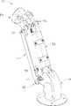
图1是本发明显示装置调整机构的立体组装图。FIG. 1 is a three-dimensional assembly view of the adjustment mechanism of the display device of the present invention.
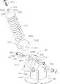
图2是本发明显示装置调整机构的立体分解图。Fig. 2 is a three-dimensional exploded view of the adjustment mechanism of the display device of the present invention.
图3是本发明显示装置调整机构另一视角的部分立体分解图。3 is a partially exploded perspective view of another viewing angle of the adjustment mechanism of the display device of the present invention.
图4是本发明显示装置调整机构俯仰组件的立体分解图。Fig. 4 is a three-dimensional exploded view of the pitch assembly of the adjustment mechanism of the display device of the present invention.
图5至图7是本发明显示装置调整机构运动过程立体图。5 to 7 are perspective views of the movement process of the adjustment mechanism of the display device of the present invention.
具体实施方式Detailed ways
本发明的较佳实施例公开一种显示装置调整机构,其适用于带有显示器的电子装置。The preferred embodiment of the present invention discloses a display device adjustment mechanism, which is suitable for an electronic device with a display.
请参见图1,本较佳实施例所述的显示装置调整机构50包括一个底座51、一个支撑组件52、两个连杆53、一个俯仰组件54、四个第一连接组件55、两个第二连接组件56、一个第三连接组件57及两个第四连接组件58。Please refer to Fig. 1, the display
请参见图2及图3,所述底座51包括一个底板511、一个主体512及由该主体512端部凸设的凸起部514。底板511为平板状,其用于将液晶显示器支撑于桌面上,主体512设于底板511上。该凸起部514包括一个凸轮面5142,主体512上开设有一个贯穿主体512两侧的贯穿孔516,且主体512侧部还设有左右对称的两个凸起518,该凸起518上开设有通孔5182。Referring to FIG. 2 and FIG. 3 , the
所述支撑组件52包括套壳521、压簧522、弹力调整螺钉523、卡环524、抵持部525、抵挡件526、滚轮527及轴528。The
该套壳521包括两个对称的横截面为匚形的主支架5211及四个连接板5212,每个主支架5211中间侧壁的两端分别凸伸一个板架5214,该板架5214上开设一个轴孔5215,以供底座51及俯仰组件54插接。四个连接板5212将两个对称的匚形主支架5211固定连接在一起。该套壳521顶部设有一个顶板(图未标),顶板上开设有一个通孔5217,以供弹力调整螺钉523及卡环524伸入。该套壳521为中空壳体,其包括一个空腔,以容纳所述压簧522、卡环524、抵持部525、抵挡件526、滚轮527及轴528。该板架5214根部还开设有一个滑槽5218。The
所述卡环524包括一个主体5241及由该主体5241两端分别向外延伸的径向宽度大于主体5241的圆盘部5242,该主体5241内设有内螺纹5243。套壳521的顶板在升降机构50组装前平行于主支架5211而延伸,组装时,先将卡环524的一个圆盘部5242及主体5241伸入套壳521的空腔内,然后将顶板弯折使卡环524的另一个圆盘部5242无法进入套壳521的空腔而露出于套壳521外。所述弹力调整螺钉523及卡环524共同构成一个调节机构(图未标)。The
所述抵挡件526包括一个基板5261及由该基板5261两侧向外垂直延伸的侧挡板5262,该两侧挡板5262上分别设有通孔5263。The resisting
所述压簧522设于抵持部525及抵挡件526之间,该压簧522两端分别抵于抵持部525及抵挡件526的基板5261。该弹力调整螺钉523与卡环524配合并抵持于抵挡件526上。该滚轮527通过轴528装配于抵挡件526的两个侧挡板5262之间。The
所述每个连杆53包括杆体部530及设于杆体部530两端的第一弯曲端531及第二弯曲端532,该第一弯曲端531及第二弯曲端532上分别开设一个螺孔5311、5321。两个连杆53分别设在支撑组件52的两相对侧。Each connecting
请同时参见图4,所述俯仰组件54包括一个第一连接件541、一个第二连接件542、一个固定轴543、一个套筒544、两个扭簧545、两个摩擦片546及两个垫片547。该第一连接件541用于与显示装置连接,该第二连接件542用于与支撑组件52连接。Please also refer to FIG. 4, the
所述第一连接件541包括一个基板5412及由该基板5412两端垂直延伸的两侧挡板5413。该两侧挡板5413上下侧边分别设有一个朝两个侧挡板5413之间延伸的挡片5414、5415,该挡片5415端部设有一弯曲部5416。该两侧挡板5413上分别设有一通孔5417,用以供固定轴543穿过。The first connecting
所述第二连接件542包括一个连接部5421、由连接部5421连接的两个对称的侧壁5422及从该侧壁5422向外延伸的凸块5423。该侧壁5422上下分别设有一个凸起5428,该侧壁5422顶部开设有通孔5424,底部开设有枢接孔5425。该凸块5423的厚度小于侧壁5422,从而形成一个阶梯面,该阶梯面为曲面5426。该凸块5423上开设有一通孔5427。The second connecting
所述固定轴543包含一个主体5431及由该主体5431两端向外延伸形成的径向宽度大于主体5431的圆盘部5432、5433。该圆盘部5432为组装时铆合形成。所述套筒544为中空圆柱状,所述扭簧545包括两端延伸的卡脚5451、5452。所述每一个摩擦片546中央开设一通孔5462。所述每一个垫片547中央开设一通孔5472。The fixed shaft 543 includes a main body 5431 and disc portions 5432 , 5433 extending outward from both ends of the main body 5431 and having a radial width greater than that of the main body 5431 . The disc portion 5432 is formed by riveting during assembly. The sleeve 544 is a hollow cylinder, and the torsion spring 545 includes clamp feet 5451 and 5452 extending from both ends. A through hole 5462 is defined in the center of each friction plate 546 . A through hole 5472 is defined in the center of each gasket 547 .
所述第一连接组件55包括一个螺钉551及两个摩擦片552。The
所述第二连接组件56包括一个螺钉561、一个弹片562、两个摩擦片563及一个螺帽564。The
所述第三连接组件57包括一个螺钉571、两个弹片572、两个摩擦片573及螺帽574。The third connecting
所述第四连接组件58包括一个垫块581、一个摩擦片582及一个紧固块583。The
请参见图1、图2及图4,组装时,可先将俯仰组件54组装起来。先将两个扭簧545套设于套筒544上,然后将固定轴543的圆盘部5433的相对端依次穿过一个摩擦片546、第一连接件541一个侧挡板5413上的通孔5417、一个垫片547、第二连接件542一个侧壁5422顶端的通孔5424、套筒544、第二连接件542另一侧壁5422顶端的通孔5424、另一垫片547及第一连接件541另一侧挡板5413上的通孔5417及另一个摩擦片546,最后将固定轴543圆盘部5433的相对端铆合从而形成圆盘部5432。该扭簧545的一个卡脚5451抵靠于第二连接件542的连接轴5421,另一卡脚5452抵靠于第一连接件541的挡片5415的弯曲部5416。第一连接件541上的挡片5414、5415与第二连接件542的侧壁5422上的凸起5428配合限制第一连接件541相对第二连接件542的转动范围。Please refer to FIG. 1 , FIG. 2 and FIG. 4 , when assembling, the
接着组装支撑组件52,先用四个连接板5212将两个主支架5211组装在一起形成套壳521,接着将卡环524的一个圆盘部5242及主体5241伸入套壳521的空腔内,然后将套壳521顶部的顶板弯折使卡环524的另一个圆盘部5242无法进入套壳521的空腔而露出套壳521外。接着将抵持部525、压簧522、抵挡件526、滚轮527、两个垫块581及两个摩擦片582依次设置于套壳521的空腔内。然后将轴528依次穿过套壳521的一个板架5214上的滑槽5218、一个摩擦片582、抵挡件526的一个侧挡板5262的通孔5263、一个垫块581、滚轮527、另一个垫块581、抵挡件526的另一个侧挡板5262的通孔5263、另一个摩擦片582及套壳521的另一个板架5214上的滑槽5218,再用两个紧固块583分别与轴528两端锁合。然后,将弹力调整螺钉523旋入卡环524,至此,支撑组件52组装完毕。此时,弹力调整螺钉523端部抵持抵持部525,调整弹力调整螺钉523与卡环524的配合程度可调整压簧522的预定压缩量,压簧522两端分别抵持抵持部525及抵挡件526。Then the
接着将第三连接组件57的螺钉571依次穿过一个弹片572、套壳521的一个板架5214上的螺孔5215、一个摩擦片573、底座51上的贯穿孔516、另一个摩擦片573、板架5214上的螺孔5215及弹片572,再通过螺钉571与螺帽574的螺合使支撑组件52与底座51固定在一起。此时,使得滚轮527与底座51的凸起部514的凸轮面5142配合。Then the
接着将第二连接组件56的螺钉561依次穿过弹片562、套壳521的一个板架5214上的螺孔5215、一个摩擦片563、第二连接件542的凸块5423上的螺孔5427、另一个摩擦片563,再通过螺钉56与螺帽567螺合从而将支撑组件52与第二连接件542固定在一起。Then the
接着将第一连接组件55的螺钉551依次穿过一个摩擦片552、连杆53的第一弯曲部531上的螺孔5311、第二连接件542的侧壁5422底部的细孔5425及另一摩擦片552将两个连杆53与第二连接件542固定在一起。同样的,螺钉551依次穿过摩擦片552、连杆53的第二弯曲部532上的螺孔5321、另一摩擦片552及底座51的凸起518上的通孔5182,从而将两个连杆53与底座51连接在一起。其中,该连杆53、主支架5211的侧壁(图未标)及该主支架5211上下两个板架5214、第二连接件542及底座51的主体512形成两组四连杆结构。Then the
请再参见图5至图7,所示为使用显示装置调整机构50调节显示装置高度的过程。如图5所示,显示装置调整机构50处于一个高度较低的起始状态,滚轮527处于凸起部514的凸轮面5142的底部。如图6、图7所示,调整所述四连杆结构,即使第二连接件542相对第一连接件541转动,套壳521相对底座51转动,从而实现对显示装置高度的调整,随着显示装置高度的不断改变,滚轮527沿凸起部514的凸轮面5142向另一端滑动。在此过程中,第四连接组件58的紧固块583在套壳521的滑槽5218内滑动。当显示装置调整机构50被推到预定位置时,停止对支撑组件52施加作用力,显示装置调整机构50在支撑组件52的套壳521与底座51之间的摩擦力、第一连接组件55、第二连接组件56及第三连接组件57的摩擦片于其他部件的摩擦力作用下使显示装置停留在任意位置。Please refer to FIG. 5 to FIG. 7 again, which show the process of adjusting the height of the display device using the display
在本实施例中,随着显示装置调整机构50高度改变,该显示装置调整机构50与水平面夹角保持在0度到65度之间。可以理解,当改变滚轮527的直径大小及底座51的凸起部514的凸轮面5142的形状时,可以随之改变显示装置调整机构50与水平面的夹角范围。在此高度调整过程中,由于滚轮527为沿光滑、连续的凸轮面5142滚动,运动较为顺畅,使用者调整时易于操作。In this embodiment, as the height of the display
进一步地,当使用显示装置调整机构50调节显示装置的倾角时,可保持该支撑组件52及连杆53与该底座51的相对位置关系,而旋转显示装置,此时,该显示装置将相对该俯仰组件54产生一个重力矩。由于该第一连接件541固定在该显示装置上,因此,该第一连接件541将随该显示装置转动。在该显示装置和该第一连接件541一起相对该支撑组件52及连杆53与该底座51转动过程中,由于该扭簧545的一个卡脚5452抵靠到第一连接件541的挡片5415端部的弯曲部5416,另一卡脚5451抵靠到第二连接件542的连接轴5421,因此,该扭簧545在此过程中受到扭力作用而产生弹性变形,并由此产生一个与重力矩方向相反的扭力矩。二者相对转动到任意倾角后,通过该扭力矩与该重力矩的平衡可以使该显示装置保持该倾角位置,从而实现调整该显示装置倾角的目的。Further, when using the display
相对现有技术,在四连杆结构运动的过程中,压簧522抵持于四连杆结构的抵持部525及抵挡件526之间,抵挡件526受到的抵持力通过轴528作用于滚轮527,并通过滚轮527与凸轮面5142之间的滚动配合作用于底座51。通过压簧522的弹性回复力使得四连杆结构的支撑组件52与连杆53之间的距离趋向于最小,即使得四连杆结构始终具有升高的趋势,可在一定程度上平衡显示装置的重力。即使两个连杆53与第一连接组件55及套壳521的板架5214与第二连接组件56的各个连接元件仅靠较小的摩擦力即可实现显示装置于特定高度的定位。因此,显示装置调整机构50具有良好的定位效果及稳定性。Compared with the prior art, during the movement of the four-bar linkage structure, the
可以理解,只要是该弹性件的弹力直接或间接的作用于四连杆结构的至少两连杆,使四连杆结构的相对两连杆之间的距离具有减小的趋势,从而使四连杆结构始终具有升高的趋势,即可实现本发明的技术效果。It can be understood that as long as the elastic force of the elastic member directly or indirectly acts on at least two links of the four-link structure, the distance between the opposite two links of the four-link structure tends to decrease, so that the four-link The rod structure always has a rising tendency, and the technical effect of the present invention can be realized.
例如,在该四连杆结构的相邻两连杆之间设置一个扭簧,该扭簧的两端分别固定于该相邻两连杆上,在该四连杆结构运动过程中,该扭簧的两端趋向于张开,其弹力直接作用于该相邻两连杆上,并使得该四连杆结构的相对两连杆之间的距离具有减小的趋势。For example, a torsion spring is arranged between two adjacent connecting rods of the four-bar linkage structure, and the two ends of the torsion spring are respectively fixed on the adjacent two connecting rods. During the movement of the four-bar linkage structure, the torsion spring The two ends of the spring tend to open, and its elastic force directly acts on the two adjacent connecting rods, and makes the distance between the two opposite connecting rods of the four-link structure tend to decrease.
又如,在该四连杆结构的相邻两连杆之间设置一个拉簧,该拉簧的两端分别钩设于该相邻两连杆上,在该四连杆结构运动过程中,该拉簧趋向于压缩,其弹力直接作用于该相邻两连杆上,并使得该四连杆结构的相对两连杆之间的距离具有减小的趋势。As another example, a tension spring is arranged between two adjacent links of the four-link structure, and the two ends of the tension spring are respectively hooked on the two adjacent links. During the movement of the four-link structure, The tension spring tends to be compressed, and its elastic force directly acts on the two adjacent connecting rods, and makes the distance between the two opposite connecting rods of the four-link structure tend to decrease.
可以理解,也可于该四连杆结构的相对两连杆之间设置一与相邻两连杆不平行的压簧或拉簧,通过压簧的推抵作用或拉簧的拉拢作用使四连杆结构的相对两连杆之间的距离具有减小的趋势。It can be understood that a compression spring or a tension spring that is not parallel to the adjacent two linkages can also be set between the opposite two linkages of the four-bar linkage structure, and the four can be made The distance between two opposing connecting rods of the connecting rod structure tends to decrease.
进一步,通过改变显示装置调整机构50的底座51及调整弹力调整螺钉523旋入卡环524的程度,可以改变压簧522的压缩量,从而调整其弹力的大小,进而使显示装置调整机构50可以承受不同重量的显示装置,即可随意改变显示装置的大小而无需随之改变显示装置调整机构50的结构及强度等其他设计参数。Further, by changing the
可以理解,本实施例中只要一个四连杆结构也可实现本发明的技术效果。It can be understood that only one four-bar linkage structure in this embodiment can also achieve the technical effect of the present invention.
可以理解,本实施例中该四连杆结构中的卡环524可以省略,该调整机构可由一个螺钉523及与该套壳521一体成形的具有内螺纹的螺合部代替。It can be understood that in this embodiment, the
可以理解,上述卡环524也可通过焊接等连接方式设于套壳521上。It can be understood that the above-mentioned
此外,该支撑组件52中的压簧522也可由其他弹性件代替。In addition, the
另外,本领域技术人员还可在本发明精神内做其它变化,当然,这些依据本发明精神所做的变化,都应包含在本发明所要求保护的范围内。In addition, those skilled in the art can also make other changes within the spirit of the present invention. Of course, these changes made according to the spirit of the present invention should be included in the scope of protection claimed by the present invention.
Claims (10)
- [claim 1] a kind of regulating mechanism for display equipment, comprise at least one four-bar linkage structure, it is characterized in that: this regulating mechanism for display equipment also comprises an elastic component, at least two connecting rods that act on four-bar linkage structure that the elastic force of this elastic component is direct or indirect make the distance between relative two connecting rods of this four-bar linkage structure have the trend that reduces; This regulating mechanism for display equipment also comprises a governor motion, in order to regulate the elastic force scope of this elastic component.
- [claim 2] regulating mechanism for display equipment as claimed in claim 1, it is characterized in that: this regulating mechanism for display equipment also comprises base, one end of this four-bar linkage structure is connected rotationally with this base, also be provided with a support division in this four-bar linkage structure, this elastic component is arranged between the support division of four-bar linkage structure and the base so that resist force to be provided, and makes the distance between relative two connecting rods of this four-bar linkage structure have the trend that reduces; This display device body adjusting mechanism also comprises a governor motion, thereby this governor motion is regulated the size that the elastic force size of elastic component changes the display device of this regulating mechanism for display equipment institute load-bearing.
- [claim 3] regulating mechanism for display equipment as claimed in claim 2, it is characterized in that: this display device is adjusted structure and is also comprised roller, is arranged at the abutment in the four-bar linkage structure and is arranged at lug boss on the base, this roller is by being located in this abutment, this elastic component one end supports the support division of this four-bar linkage structure, the other end supports this abutment, makes to roll on the lug boss on roller and the base.
- [claim 4] regulating mechanism for display equipment as claimed in claim 3 is characterized in that: offer two relative chutes on this four-bar linkage structure, this roller is located between these two chutes, and the two ends of this axle slidably are arranged in these two chutes.
- [claim 5] regulating mechanism for display equipment as claimed in claim 1 is characterized in that: this elastic component is a stage clip.
- [claim 6] regulating mechanism for display equipment as claimed in claim 2 is characterized in that: this adjusting mechanism comprises screw and is located at snap ring on this supporting component.
- [claim 7] regulating mechanism for display equipment as claimed in claim 5 is characterized in that: this adjusting mechanism comprises that a screw reaches and the screw part of the tool internal thread that this supporting component is integrally formed.
- [claim 8] regulating mechanism for display equipment as claimed in claim 2 is characterized in that: this regulating mechanism for display equipment also comprises a pitching assembly, and an end of this four-bar linkage structure is connected rotationally with the pitching assembly.
- [claim 9] regulating mechanism for display equipment as claimed in claim 8, it is characterized in that: this pitching assembly comprises first web member and second web member, this first web member comprises a catch, this second web member comprises a projection, and this catch matches with this projection and limits the angular range that first web member rotates relative to second web member.
- [claim 10] regulating mechanism for display equipment as claimed in claim 9 is characterized in that: this pitching assembly also comprises two torsion springs, and this torsion spring comprises two card bases; This catch comprises a bend, and this second web member comprises a coupling shaft; Two card bases of this torsion spring are arranged in respectively on this bend and this coupling shaft.
Priority Applications (2)
| Application Number | Priority Date | Filing Date | Title |
|---|---|---|---|
| CN2007102035414ACN101471144B (en) | 2007-12-28 | 2007-12-28 | Regulating mechanism for display equipment |
| US12/200,434US8011632B2 (en) | 2007-12-28 | 2008-08-28 | Support stand for flat-panel display monitor |
Applications Claiming Priority (1)
| Application Number | Priority Date | Filing Date | Title |
|---|---|---|---|
| CN2007102035414ACN101471144B (en) | 2007-12-28 | 2007-12-28 | Regulating mechanism for display equipment |
Publications (2)
| Publication Number | Publication Date |
|---|---|
| CN101471144Atrue CN101471144A (en) | 2009-07-01 |
| CN101471144B CN101471144B (en) | 2013-06-05 |
Family
ID=40796944
Family Applications (1)
| Application Number | Title | Priority Date | Filing Date |
|---|---|---|---|
| CN2007102035414AExpired - Fee RelatedCN101471144B (en) | 2007-12-28 | 2007-12-28 | Regulating mechanism for display equipment |
Country Status (2)
| Country | Link |
|---|---|
| US (1) | US8011632B2 (en) |
| CN (1) | CN101471144B (en) |
Cited By (12)
| Publication number | Priority date | Publication date | Assignee | Title |
|---|---|---|---|---|
| US20120138754A1 (en)* | 2009-05-12 | 2012-06-07 | Seong Wong Lim | Universal Frame For Flat Panel Displays |
| CN103108778A (en)* | 2010-09-17 | 2013-05-15 | 约翰逊控股公司 | Assembly for moving projection screens for head-up displays |
| CN104217648A (en)* | 2014-07-31 | 2014-12-17 | 苏州佳世达电通有限公司 | Display device |
| TWI469639B (en)* | 2011-12-19 | 2015-01-11 | Top Victory Invest Ltd | Detachable connection |
| CN103486414B (en)* | 2012-06-11 | 2016-01-20 | 兆利科技工业股份有限公司 | Support structure |
| CN106090558A (en)* | 2016-06-28 | 2016-11-09 | 泰州市创新电子有限公司 | Slender upright post type lifting support frame |
| CN108015778A (en)* | 2017-12-04 | 2018-05-11 | 深圳市优必选科技有限公司 | Shoulder armor structure and robot |
| CN108758241A (en)* | 2018-08-08 | 2018-11-06 | 苏州胜利精密制造科技股份有限公司 | A kind of rotating base of double-feet support |
| CN109074130A (en)* | 2016-04-14 | 2018-12-21 | 微软技术许可有限责任公司 | Equipment with rotatable display |
| CN110043779A (en)* | 2019-04-25 | 2019-07-23 | 江苏汉和唐智能科技有限公司 | A kind of display bracket |
| CN114321635A (en)* | 2021-12-31 | 2022-04-12 | 联想(北京)有限公司 | Supporting device and electronic equipment |
| CN115111499A (en)* | 2022-06-24 | 2022-09-27 | 东莞耀生光电科技有限公司 | Display device rotating seat |
Families Citing this family (57)
| Publication number | Priority date | Publication date | Assignee | Title |
|---|---|---|---|---|
| USD645868S1 (en) | 2010-06-09 | 2011-09-27 | Colebrook Bosson Saunders (Products) Limited | Display support |
| USD688674S1 (en) | 1920-12-09 | 2013-08-27 | Colebrook Bosson Saunders (Products) Limited | Display support |
| CN101471145A (en)* | 2007-12-27 | 2009-07-01 | 鸿富锦精密工业(深圳)有限公司 | Lifting mechanism |
| CN201267069Y (en)* | 2008-06-27 | 2009-07-01 | 比亚迪股份有限公司 | Portable electronic apparatus |
| CN101737602B (en)* | 2008-11-17 | 2012-08-29 | 鸿富锦精密工业(深圳)有限公司 | Supporting mechanism and lifting mechanism adopting same |
| US8523131B2 (en)* | 2009-10-08 | 2013-09-03 | Innovative Office Products, Inc. | Tilter for positioning an electronic device |
| US8363391B2 (en)* | 2010-01-26 | 2013-01-29 | Samsung Electronics Co., Ltd. | Portable terminal |
| JP4923121B2 (en)* | 2010-02-25 | 2012-04-25 | 東芝テック株式会社 | Display device and display device system |
| US20110260017A1 (en)* | 2010-04-23 | 2011-10-27 | Humanscale Corporation | Adjustable Support Arm |
| US10281080B1 (en) | 2010-06-04 | 2019-05-07 | Kurt William Massey | Adjustable mounting systems for televisions |
| US8724037B1 (en) | 2010-06-04 | 2014-05-13 | Kurt William Massey | Mounting system |
| US9074721B2 (en) | 2010-06-09 | 2015-07-07 | Alex Lau | Support system |
| US9316346B2 (en) | 2010-06-09 | 2016-04-19 | Colebrook Bosson Saunders (Products) Limited | Support system |
| USD684982S1 (en) | 2010-08-11 | 2013-06-25 | Colebrook Bosson Saunders (Products) Limited | Display support with indicator window |
| CN102374370B (en)* | 2010-08-12 | 2016-03-02 | 深圳市莫孚康技术有限公司 | A kind of spring arm device |
| US8226054B2 (en)* | 2010-10-18 | 2012-07-24 | Syncmold Enterprise Corp. | Display frame and support unit thereof |
| USD701569S1 (en)* | 2011-03-22 | 2014-03-25 | Matthew Fagan | Pantograph arm set |
| GB2512998B (en)* | 2011-08-31 | 2018-07-04 | Hewlett Packard Development Co | Display stand with latching mechanism |
| US20130119039A1 (en)* | 2011-11-11 | 2013-05-16 | Lincoln Global, Inc. | Educational welding cell unit |
| GB201201903D0 (en)* | 2012-02-03 | 2012-03-21 | Amsafe Bridport Ltd | Mounting assembly |
| CN102620125A (en)* | 2012-03-20 | 2012-08-01 | 李宇 | Display support and spiral arm thereof |
| TWM438098U (en)* | 2012-04-30 | 2012-09-21 | ming-xian Huang | Supporting apparatus |
| TWI515385B (en)* | 2012-06-05 | 2016-01-01 | 緯創資通股份有限公司 | Adjustable supporting device |
| WO2014070141A1 (en) | 2012-10-30 | 2014-05-08 | Hewlett-Packard Development Company, L.P. | Support assembly for a device |
| US9657889B1 (en) | 2013-03-15 | 2017-05-23 | Humanscale Corporation | Adjustable support arm |
| JP5686846B2 (en)* | 2013-05-27 | 2015-03-18 | シャープ株式会社 | Display device holding mechanism |
| US9033292B2 (en)* | 2013-08-21 | 2015-05-19 | Continew Inc. | Load supporting apparatus |
| US9371955B2 (en)* | 2013-10-07 | 2016-06-21 | Ergotron, Inc. | Bi-directional tilt mechanisms and methods |
| WO2015143009A1 (en)* | 2014-03-19 | 2015-09-24 | Ergotron, Inc. | Lift stand with arms |
| TWM494601U (en)* | 2014-08-21 | 2015-02-01 | Melten Corp | Supporting bracket and medical cart |
| US9802307B2 (en)* | 2015-09-02 | 2017-10-31 | Lockheed Martin Corporation | Locking intermediate link for a tool arm assembly |
| US9936593B2 (en) | 2016-04-14 | 2018-04-03 | Microsoft Technology Licensing, Llc | Device with a rotatable display |
| US10159158B2 (en) | 2016-04-14 | 2018-12-18 | Microsoft Technology Licensing, Llc | Device with a rotatable display |
| US10345851B2 (en)* | 2016-04-14 | 2019-07-09 | Microsoft Technology Licensing, Llc | Device with a rotatable display |
| US10172248B1 (en) | 2016-04-14 | 2019-01-01 | Microsoft Technology Licensing, Llc | Device with a rotatable display |
| US10999944B2 (en) | 2016-04-26 | 2021-05-04 | Microsoft Technology Licensing, Llc | Structural device cover |
| US9946309B2 (en) | 2016-06-10 | 2018-04-17 | Microsoft Technology Licensing, Llc | Device wiring |
| US12152720B1 (en) | 2017-04-17 | 2024-11-26 | Manehu Product Alliance, Llc | Adjustable mounting systems for televisions |
| US11118729B2 (en)* | 2017-06-09 | 2021-09-14 | Teknion Limited | Adjustable counterbalancing display support |
| CN108170219B (en)* | 2018-02-11 | 2024-04-30 | 鞍山佳创博科技有限公司 | Integrated computer display screen hovering mechanism and integrated computer comprising same |
| KR102615049B1 (en)* | 2018-03-07 | 2023-12-19 | 삼성메디슨 주식회사 | Ultrasonic Diagnostic Apparatus |
| US10851938B2 (en) | 2018-04-02 | 2020-12-01 | Humanscale Corporation | Adjustable support arm |
| US11415201B2 (en)* | 2019-05-31 | 2022-08-16 | Apple Inc. | Display lift arm |
| WO2021127552A1 (en)* | 2019-12-19 | 2021-06-24 | Manehu Product Alliance, Llc, D/B/A | Adjustable display mounting system |
| WO2021159112A1 (en) | 2020-02-08 | 2021-08-12 | MANEHU PRODUCT ALLIANCE, LLC, d/b/a MANTELMOUNT | Display mounting system with adjustable weight counterbalance |
| US11287080B2 (en) | 2020-02-10 | 2022-03-29 | Manehu Product Alliance, Llc | Multidirectional display mount |
| TWM609479U (en)* | 2020-04-01 | 2021-03-21 | 信錦企業股份有限公司 | Grinding device |
| CN114636075B (en)* | 2020-12-16 | 2023-10-13 | 纬创资通(中山)有限公司 | Biaxial pivoting assembly and angle adjusting device |
| CN112578159B (en)* | 2020-12-25 | 2024-08-06 | 国网安徽省电力有限公司芜湖供电公司 | Fixing equipment for terminal device |
| US12024094B2 (en) | 2021-06-08 | 2024-07-02 | Adrian Steel Company | Tool mounting device |
| US11892122B2 (en)* | 2021-09-27 | 2024-02-06 | Sunbeom HWANG | Vibration-proof hanger |
| CN114046030A (en)* | 2021-11-12 | 2022-02-15 | 广州工程总承包集团有限公司 | Connection construction method of cantilever outer frame |
| CN114636079A (en)* | 2022-03-18 | 2022-06-17 | 东莞市擎易五金科技有限公司 | A smoothly adjustable display stand |
| CN115363377A (en)* | 2022-07-08 | 2022-11-22 | 浙江安吉万诺智能家居有限公司 | Self-adaptation growth mechanism of chasing after one's back and seat |
| CN116255548A (en)* | 2022-12-29 | 2023-06-13 | 深圳市倍思奇创新科技有限公司 | Spring Balanced Vertical Tilt Mechanism for Monitor Arms |
| CN116255527A (en)* | 2022-12-29 | 2023-06-13 | 深圳市倍思奇创新科技有限公司 | Display support vertical tilting mechanism with eccentric gear |
| US12309952B1 (en)* | 2023-03-29 | 2025-05-20 | Oxti Pte Ltd | Electronic device holder |
Family Cites Families (15)
| Publication number | Priority date | Publication date | Assignee | Title |
|---|---|---|---|---|
| US6478275B1 (en)* | 2001-08-31 | 2002-11-12 | Min Hwa Huang | Support device for monitor, displayer or other object |
| US20030075653A1 (en)* | 2001-10-19 | 2003-04-24 | Chin-Chu Li | Liquid crystal display support |
| KR100512718B1 (en) | 2002-07-16 | 2005-09-07 | 삼성전자주식회사 | Monitor |
| TW537479U (en)* | 2002-08-01 | 2003-06-11 | Bo-Sen Chiou | Rod connecting type ascending and descending device |
| CN2566418Y (en)* | 2002-08-08 | 2003-08-13 | 邱柏森 | Link type lifting device |
| CN2618261Y (en)* | 2003-05-03 | 2004-05-26 | 乐清市宝泰电子有限公司 | Four-bar linkage spindle of liquid-crystal displaying devices |
| CN2651895Y (en)* | 2003-09-24 | 2004-10-27 | 黄明华 | Improved monitor support arm |
| US7770856B2 (en)* | 2004-08-13 | 2010-08-10 | Hewlett-Packard Development Company, L.P. | Thin computer monitor support apparatus |
| KR100880123B1 (en)* | 2005-07-29 | 2009-01-23 | 주식회사 메디슨 | 4-joint monitor support assembly for supporting monitor of ultrasonic diagnostic device |
| TWM281089U (en)* | 2005-08-04 | 2005-11-21 | Shin Zu Shing Co Ltd | Bi-sectional pivot |
| TWM318090U (en) | 2007-02-26 | 2007-09-01 | Toptronics Inc | Supporting frame |
| TWM323553U (en) | 2007-06-12 | 2007-12-11 | Shian-Nung Huang | Single-spring supporting device |
| US7510155B2 (en)* | 2007-07-02 | 2009-03-31 | Shian-Nung Huang | Single spring supporting device |
| US7810773B2 (en)* | 2008-07-22 | 2010-10-12 | Ching-Chih Chi | Support arm structure with elastic force adjustment arrangement |
| CN101684882B (en)* | 2008-09-25 | 2012-07-18 | 鸿富锦精密工业(深圳)有限公司 | Elevator mechanism |
- 2007
- 2007-12-28CNCN2007102035414Apatent/CN101471144B/ennot_activeExpired - Fee Related
- 2008
- 2008-08-28USUS12/200,434patent/US8011632B2/ennot_activeExpired - Fee Related
Cited By (15)
| Publication number | Priority date | Publication date | Assignee | Title |
|---|---|---|---|---|
| US20120138754A1 (en)* | 2009-05-12 | 2012-06-07 | Seong Wong Lim | Universal Frame For Flat Panel Displays |
| CN103108778A (en)* | 2010-09-17 | 2013-05-15 | 约翰逊控股公司 | Assembly for moving projection screens for head-up displays |
| TWI469639B (en)* | 2011-12-19 | 2015-01-11 | Top Victory Invest Ltd | Detachable connection |
| CN103486414B (en)* | 2012-06-11 | 2016-01-20 | 兆利科技工业股份有限公司 | Support structure |
| CN104217648A (en)* | 2014-07-31 | 2014-12-17 | 苏州佳世达电通有限公司 | Display device |
| CN104217648B (en)* | 2014-07-31 | 2016-09-07 | 苏州佳世达电通有限公司 | A kind of display |
| CN109074130A (en)* | 2016-04-14 | 2018-12-21 | 微软技术许可有限责任公司 | Equipment with rotatable display |
| CN109074130B (en)* | 2016-04-14 | 2022-06-28 | 微软技术许可有限责任公司 | Device with rotatable display |
| CN106090558A (en)* | 2016-06-28 | 2016-11-09 | 泰州市创新电子有限公司 | Slender upright post type lifting support frame |
| CN108015778A (en)* | 2017-12-04 | 2018-05-11 | 深圳市优必选科技有限公司 | Shoulder armor structure and robot |
| CN108015778B (en)* | 2017-12-04 | 2023-08-04 | 深圳市优必选科技有限公司 | Shoulder armor structure and robot |
| CN108758241A (en)* | 2018-08-08 | 2018-11-06 | 苏州胜利精密制造科技股份有限公司 | A kind of rotating base of double-feet support |
| CN110043779A (en)* | 2019-04-25 | 2019-07-23 | 江苏汉和唐智能科技有限公司 | A kind of display bracket |
| CN114321635A (en)* | 2021-12-31 | 2022-04-12 | 联想(北京)有限公司 | Supporting device and electronic equipment |
| CN115111499A (en)* | 2022-06-24 | 2022-09-27 | 东莞耀生光电科技有限公司 | Display device rotating seat |
Also Published As
| Publication number | Publication date |
|---|---|
| US8011632B2 (en) | 2011-09-06 |
| US20090166501A1 (en) | 2009-07-02 |
| CN101471144B (en) | 2013-06-05 |
Similar Documents
| Publication | Publication Date | Title |
|---|---|---|
| CN101471144A (en) | Regulating mechanism for display equipment | |
| CN101471145A (en) | Lifting mechanism | |
| CN101713487B (en) | Lifting mechanism | |
| JP5732551B2 (en) | Reclining stand system and method | |
| US10309582B2 (en) | Supporting module | |
| KR100710314B1 (en) | Monitor stand | |
| CN101676975B (en) | Display apparatus | |
| CN110630867B (en) | Electronic equipment and supporting structure thereof | |
| CN101737417B (en) | Hinge structure | |
| CN101453852A (en) | Lifting mechanism | |
| CN101625069A (en) | Elevator mechanism | |
| CN210890841U (en) | Liftable supporting device | |
| CN101619800A (en) | Elevation mechanism | |
| JP3221114U (en) | Support frame | |
| CN101661689A (en) | Display device | |
| EP4112991B1 (en) | Display stand holder with slide rail structure and display apparatus thereof | |
| CN113365531B (en) | Display rack and display rack system | |
| CN212617250U (en) | pivot seat | |
| TWI333038B (en) | Adjusting machanism of display devices | |
| JP3096746U (en) | LCD television | |
| TWI426198B (en) | Supporting mechanism | |
| CN101660649B (en) | Adjustable translation structure and display device with same | |
| US20060174457A1 (en) | Stepless height adjusting apparatus | |
| JP7272129B2 (en) | Display stands and display systems | |
| CN203823369U (en) | Supporting device |
Legal Events
| Date | Code | Title | Description |
|---|---|---|---|
| C06 | Publication | ||
| PB01 | Publication | ||
| C10 | Entry into substantive examination | ||
| SE01 | Entry into force of request for substantive examination | ||
| C14 | Grant of patent or utility model | ||
| GR01 | Patent grant | ||
| C17 | Cessation of patent right | ||
| CF01 | Termination of patent right due to non-payment of annual fee | Granted publication date:20130605 Termination date:20131228 |