CN101470125B - Automatic analysis device and sample processing system - Google Patents
Automatic analysis device and sample processing systemDownload PDFInfo
- Publication number
- CN101470125B CN101470125BCN2008101844562ACN200810184456ACN101470125BCN 101470125 BCN101470125 BCN 101470125BCN 2008101844562 ACN2008101844562 ACN 2008101844562ACN 200810184456 ACN200810184456 ACN 200810184456ACN 101470125 BCN101470125 BCN 101470125B
- Authority
- CN
- China
- Prior art keywords
- rack
- sample
- unit
- input
- specimen
- Prior art date
- Legal status (The legal status is an assumption and is not a legal conclusion. Google has not performed a legal analysis and makes no representation as to the accuracy of the status listed.)
- Active
Links
Images


Classifications
- G—PHYSICS
- G01—MEASURING; TESTING
- G01N—INVESTIGATING OR ANALYSING MATERIALS BY DETERMINING THEIR CHEMICAL OR PHYSICAL PROPERTIES
- G01N35/00—Automatic analysis not limited to methods or materials provided for in any single one of groups G01N1/00 - G01N33/00; Handling materials therefor
- G01N35/02—Automatic analysis not limited to methods or materials provided for in any single one of groups G01N1/00 - G01N33/00; Handling materials therefor using a plurality of sample containers moved by a conveyor system past one or more treatment or analysis stations
- G01N35/04—Details of the conveyor system
- G—PHYSICS
- G01—MEASURING; TESTING
- G01N—INVESTIGATING OR ANALYSING MATERIALS BY DETERMINING THEIR CHEMICAL OR PHYSICAL PROPERTIES
- G01N35/00—Automatic analysis not limited to methods or materials provided for in any single one of groups G01N1/00 - G01N33/00; Handling materials therefor
- G01N35/02—Automatic analysis not limited to methods or materials provided for in any single one of groups G01N1/00 - G01N33/00; Handling materials therefor using a plurality of sample containers moved by a conveyor system past one or more treatment or analysis stations
- G01N35/026—Automatic analysis not limited to methods or materials provided for in any single one of groups G01N1/00 - G01N33/00; Handling materials therefor using a plurality of sample containers moved by a conveyor system past one or more treatment or analysis stations having blocks or racks of reaction cells or cuvettes
- G—PHYSICS
- G01—MEASURING; TESTING
- G01N—INVESTIGATING OR ANALYSING MATERIALS BY DETERMINING THEIR CHEMICAL OR PHYSICAL PROPERTIES
- G01N35/00—Automatic analysis not limited to methods or materials provided for in any single one of groups G01N1/00 - G01N33/00; Handling materials therefor
- G01N35/10—Devices for transferring samples or any liquids to, in, or from, the analysis apparatus, e.g. suction devices, injection devices
- G—PHYSICS
- G01—MEASURING; TESTING
- G01N—INVESTIGATING OR ANALYSING MATERIALS BY DETERMINING THEIR CHEMICAL OR PHYSICAL PROPERTIES
- G01N35/00—Automatic analysis not limited to methods or materials provided for in any single one of groups G01N1/00 - G01N33/00; Handling materials therefor
- G01N2035/00178—Special arrangements of analysers
- G01N2035/00326—Analysers with modular structure
- G—PHYSICS
- G01—MEASURING; TESTING
- G01N—INVESTIGATING OR ANALYSING MATERIALS BY DETERMINING THEIR CHEMICAL OR PHYSICAL PROPERTIES
- G01N35/00—Automatic analysis not limited to methods or materials provided for in any single one of groups G01N1/00 - G01N33/00; Handling materials therefor
- G01N35/02—Automatic analysis not limited to methods or materials provided for in any single one of groups G01N1/00 - G01N33/00; Handling materials therefor using a plurality of sample containers moved by a conveyor system past one or more treatment or analysis stations
- G01N35/04—Details of the conveyor system
- G01N2035/046—General conveyor features
- G01N2035/0462—Buffers [FIFO] or stacks [LIFO] for holding carriers between operations
- G—PHYSICS
- G01—MEASURING; TESTING
- G01N—INVESTIGATING OR ANALYSING MATERIALS BY DETERMINING THEIR CHEMICAL OR PHYSICAL PROPERTIES
- G01N35/00—Automatic analysis not limited to methods or materials provided for in any single one of groups G01N1/00 - G01N33/00; Handling materials therefor
- G01N35/02—Automatic analysis not limited to methods or materials provided for in any single one of groups G01N1/00 - G01N33/00; Handling materials therefor using a plurality of sample containers moved by a conveyor system past one or more treatment or analysis stations
- G01N35/04—Details of the conveyor system
- G01N2035/046—General conveyor features
- G01N2035/0465—Loading or unloading the conveyor
- G—PHYSICS
- G01—MEASURING; TESTING
- G01N—INVESTIGATING OR ANALYSING MATERIALS BY DETERMINING THEIR CHEMICAL OR PHYSICAL PROPERTIES
- G01N35/00—Automatic analysis not limited to methods or materials provided for in any single one of groups G01N1/00 - G01N33/00; Handling materials therefor
- G01N35/02—Automatic analysis not limited to methods or materials provided for in any single one of groups G01N1/00 - G01N33/00; Handling materials therefor using a plurality of sample containers moved by a conveyor system past one or more treatment or analysis stations
- G01N35/04—Details of the conveyor system
- G01N2035/046—General conveyor features
- G01N2035/0467—Switching points ("aiguillages")
- Y—GENERAL TAGGING OF NEW TECHNOLOGICAL DEVELOPMENTS; GENERAL TAGGING OF CROSS-SECTIONAL TECHNOLOGIES SPANNING OVER SEVERAL SECTIONS OF THE IPC; TECHNICAL SUBJECTS COVERED BY FORMER USPC CROSS-REFERENCE ART COLLECTIONS [XRACs] AND DIGESTS
- Y10—TECHNICAL SUBJECTS COVERED BY FORMER USPC
- Y10T—TECHNICAL SUBJECTS COVERED BY FORMER US CLASSIFICATION
- Y10T436/00—Chemistry: analytical and immunological testing
- Y10T436/11—Automated chemical analysis
- Y10T436/113332—Automated chemical analysis with conveyance of sample along a test line in a container or rack
- Y—GENERAL TAGGING OF NEW TECHNOLOGICAL DEVELOPMENTS; GENERAL TAGGING OF CROSS-SECTIONAL TECHNOLOGIES SPANNING OVER SEVERAL SECTIONS OF THE IPC; TECHNICAL SUBJECTS COVERED BY FORMER USPC CROSS-REFERENCE ART COLLECTIONS [XRACs] AND DIGESTS
- Y10—TECHNICAL SUBJECTS COVERED BY FORMER USPC
- Y10T—TECHNICAL SUBJECTS COVERED BY FORMER US CLASSIFICATION
- Y10T436/00—Chemistry: analytical and immunological testing
- Y10T436/11—Automated chemical analysis
- Y10T436/115831—Condition or time responsive
Landscapes
- Chemical & Material Sciences (AREA)
- Biochemistry (AREA)
- Physics & Mathematics (AREA)
- Health & Medical Sciences (AREA)
- Life Sciences & Earth Sciences (AREA)
- Analytical Chemistry (AREA)
- General Health & Medical Sciences (AREA)
- General Physics & Mathematics (AREA)
- Immunology (AREA)
- Pathology (AREA)
- Chemical Kinetics & Catalysis (AREA)
- Automatic Analysis And Handling Materials Therefor (AREA)
- Sampling And Sample Adjustment (AREA)
Abstract
Description
Translated fromChinese技术领域technical field
本发明涉及检体处理系统,涉及利用输送检体齿条的输送线来连接功能和处理能力相异的多个装置,且适于有效运用的检体处理系统。The present invention relates to a sample processing system, and relates to a sample processing system suitable for effective use by connecting a plurality of devices with different functions and processing capabilities by using a transport line for transporting a sample rack.
背景技术Background technique
血浆、血清、尿液等生物体试样的分析结果在诊断病情方面带来很多信息,在自动处理那种生物体试样的装置方面有很多现有技术。Analytical results of biological samples such as plasma, serum, and urine provide a lot of information in diagnosing diseases, and there are many prior art devices for automatically processing such biological samples.
例如,在专利文献1中公开了分析单元将齿条装入分析单元内,另外分别设置向分析单元外送出的移送元件,在分析单元的上游设置用于识别检体的委托项目的识别元件,判断应该用哪个分析单元进行作业,并向相应的分析模块发出齿条的装入指示的技术。For example, in Patent Document 1, it is disclosed that the analysis unit incorporates a rack into the analysis unit, in addition, transfer elements sent out of the analysis unit are respectively provided, and an identification element for identifying the entrusted item of the specimen is provided upstream of the analysis unit, It is a technology to judge which analysis unit should be used for the work, and issue a rack loading instruction to the corresponding analysis module.
另外,在专利文献2中沿着由带式传送器构成的输送线配置多个分析单元,在该输送线的一端侧配置齿条供给部并在另一端侧配置齿条回收部。另外,在齿条回收部的前方配置有待机部以便自动进行再次检查。In addition, in Patent Document 2, a plurality of analysis units are arranged along a conveying line constituted by a belt conveyor, a rack supply unit is arranged on one end side of the conveying line, and a rack recovering unit is arranged on the other end side of the conveying line. In addition, a standby unit is arranged in front of the rack recovery unit for automatic re-inspection.
再有,在专利文献3中,在齿条供给部和分析单元之间的齿条输送路径上设置用于使齿条待机的圆盘,用来避免齿条输送道的拥堵以及自动进行再次检查。Furthermore, in
专利文献1:特开平10-19899号公报Patent Document 1: Japanese Unexamined Patent Publication No. H10-19899
专利文献2:特开平10-213586号公报Patent Document 2: Japanese Unexamined Patent Application Publication No. H10-213586
专利文献3:特开2004-279357号公报Patent Document 3: JP-A-2004-279357
在上述的专利文献1中所记载的自动分析装置中,齿条的输送路径在齿条向分析单元输送之前既已确定,因此,在需要用多个分析单元进行分析的场合,从上游侧顺序输送,且在上游侧必须进行分析的检体有多个的场合,齿条输送路拥堵,即便有要仅在下游侧进行分析的检体也无法赶过。In the automatic analysis device described in the above-mentioned Patent Document 1, the transport path of the rack is determined before the rack is transported to the analysis unit. When there are many samples that must be analyzed on the upstream side during transportation, the rack conveyance path is congested, and even if there are samples that need to be analyzed only on the downstream side, it cannot be overtaken.
另外,在上述的专利文献2中所记载的自动分析装置中,虽然设有从下游侧向上游侧输送齿条的回程道,但在将齿条先向下游侧的分析单元输送的场合,在使齿条暂且返回到位于最上游的齿条供给单元之后必须输送到上游侧的分析单元,因而不仅浪费时间而且妨碍从供给部供给的齿条的处理。In addition, in the automatic analysis device described in the above-mentioned Patent Document 2, although a return path is provided to transport the rack from the downstream side to the upstream side, when the rack is transported to the analysis unit on the downstream side first, the The rack must be transported to the analysis unit on the upstream side after being returned to the rack supply unit most upstream, which not only wastes time but also hinders the processing of the rack supplied from the supply unit.
再有,由于需要进行自动重检的检体集结在容纳单元之前的待机部,因而在为由处理速度不同的多个分析单元构成的系统的场合,即便结果输出且有要进行重检的齿条,也无法赶过先前进入待机部的齿条,从而产生徒劳的等待时间。另外,在进行重检时因返回到供给部而浪费时间与妨碍所供给的齿条的进路其结果是相同的。In addition, since the samples that need to be automatically re-examined are gathered in the standby unit before the storage unit, in the case of a system composed of a plurality of analysis units with different processing speeds, even if the results are output and there are gears for re-examination Racks cannot overtake the racks that have previously entered the standby section, resulting in a waste of waiting time. In addition, the result of wasting time by returning to the supply unit during the re-inspection and obstructing the route of the supplied rack is the same.
在上述的专利文献3所记载的自动分析装置中,将齿条待机部用圆形的盘构成,对齿条的随机存取性优良,但由于齿条形状一般为近似长方形的形状,因此,在盘上产生死域。另外,由圆形盘引起的死域在系统整体上也较大。In the automatic analysis device described in the above-mentioned
再有,在以多台分析单元构成系统的场合,由于经由待机盘输送到下游侧的分析单元,因此,齿条的方向成为反向,有必要在下一个分析单元前将行进方向复原。Furthermore, when a system is constituted by a plurality of analysis units, the direction of the rack is reversed because it is transported to the analysis unit on the downstream side via the standby tray, and it is necessary to return the traveling direction before the next analysis unit.
发明内容Contents of the invention
本发明的目的是提供通过使齿条供给部、输送部、回收部仅具有作为原来目的的齿条输送的作用,其它处理单元所固有且需要的功能使各处理单元具有,从而使整体的处理最适合化的检体处理系统。The purpose of the present invention is to provide a rack supply unit, a transport unit, and a recovery unit that only have the function of rack transport as the original purpose, and each processing unit has the inherent and necessary functions of other processing units, so that the overall processing The most suitable sample processing system.
现有技术中的问题是使齿条输送部具有待机部等分析单元所需的功能部。A problem in the prior art is to provide the rack transport unit with functional units required for analysis units such as a standby unit.
在本发明中,通过使多个齿条待机,使各处理单元具有一对如对各个齿条可随机地进行存取的缓冲单元,并构成为用缓冲单元进行与齿条输送部的齿条输入输出,将未处理的齿条输入到缓冲单元,连自动重检也包括在内的处理结束后使齿条从缓冲单元输出,从而消除处理单元和输送单元的功能上的依存。In the present invention, by making a plurality of racks stand by, each processing unit has a pair of buffer units that can randomly access each rack, and it is configured that the buffer unit is used to carry out the rack transmission with the rack. Input and output, unprocessed racks are input to the buffer unit, and the racks are output from the buffer unit after processing including automatic re-inspection, thereby eliminating the functional dependence of the processing unit and the conveying unit.
另外,通过使在缓冲单元进行与齿条输送部的齿条转装的齿条转装部对于齿条输送单元的前往道和回程道均可存取,使得处理单元间的输送距离最短,即便是对于检体的处理内容横跨多个处理单元的场合,可从最快能够进行的处理开始进行而不会意识到多个处理单元的配置顺序。进而,由此不需要在系统上游确定齿条输送全部,确认在一个处理单元的处理结束时的其它处理单元的负载,可将齿条输送到负载最低的处理单元上,从而可缩短系统整体上的处理时间。In addition, by making the rack transfer unit that performs rack transfer with the rack transfer unit in the buffer unit accessible to both the forward and return lanes of the rack transfer unit, the transfer distance between processing units is minimized, even When the processing content of a sample spans multiple processing units, the processing can be performed from the fastest possible processing without being aware of the arrangement order of the multiple processing units. Furthermore, this eliminates the need to confirm all the rack feeds in the upstream of the system, and confirms the loads of other processing units when the processing of one processing unit is completed, so that the rack can be sent to the processing unit with the lowest load, thereby shortening the entire system. processing time.
附图说明Description of drawings
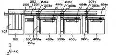
图1是本发明的一个实施例中的检体处理系统的构成图。FIG. 1 is a block diagram of a sample processing system in one embodiment of the present invention.
图2是图1的系统构成中的功能块构成图。FIG. 2 is a functional block configuration diagram in the system configuration of FIG. 1 .
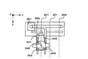
图3是本发明的一个实施例中的取样单元的构成图。Fig. 3 is a structural diagram of a sampling unit in an embodiment of the present invention.
图4取样单元的投入齿条移动机构构成图。Figure 4 is a diagram of the configuration of the input rack moving mechanism of the sampling unit.
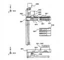
图5是本发明的一个实施例中的缓冲单元的构成图。Fig. 5 is a structural diagram of a buffer unit in an embodiment of the present invention.
图6是缓冲单元齿条转装机构构成及动作说明图。Fig. 6 is an explanatory view of the structure and operation of the rack transfer mechanism of the buffer unit.
图7是缓冲单元齿条转装机构构成及动作说明图。Fig. 7 is an explanatory view of the structure and operation of the rack transfer mechanism of the buffer unit.
图8是缓冲单元齿条转装机构构成及动作说明图。Fig. 8 is an explanatory view of the structure and operation of the rack transfer mechanism of the buffer unit.
图9是缓冲单元齿条转装机构构成及动作说明图。Fig. 9 is an explanatory diagram of the structure and operation of the rack transfer mechanism of the buffer unit.
图10是缓冲单元齿条转装机构构成及动作说明图。Fig. 10 is an explanatory view of the structure and operation of the rack transfer mechanism of the buffer unit.
图11是缓冲单元齿条转装机构构成及动作说明图。Fig. 11 is an explanatory diagram of the structure and operation of the rack transfer mechanism of the buffer unit.
图12是缓冲单元齿条转装机构构成及动作说明图。Fig. 12 is an explanatory view of the structure and operation of the rack transfer mechanism of the buffer unit.
图13是缓冲单元齿条转装机构构成及动作说明图。Fig. 13 is an explanatory view of the structure and operation of the rack transfer mechanism of the buffer unit.
图14是缓冲单元齿条转装机构构成及动作说明图。Fig. 14 is an explanatory diagram of the structure and operation of the rack transfer mechanism of the buffer unit.
图15是缓冲单元和功能模块之间的齿条输送说明图。Fig. 15 is an explanatory view of rack conveyance between the buffer unit and the functional module.
图16是缓冲单元和附属模块之间的齿条输送说明图。Fig. 16 is an explanatory diagram of rack conveyance between the buffer unit and the accessory module.
图17是齿条输送路径确定的流程图。Fig. 17 is a flow chart of rack conveyance path determination.
图18是本发明的一个实施例中的齿条流动的说明图。Fig. 18 is an explanatory view of rack flow in one embodiment of the present invention.
图19是本发明的一个实施例中的齿条流动的说明图。Fig. 19 is an explanatory view of rack flow in one embodiment of the present invention.
图20是紧急检体投入时的齿条流程的说明图。Fig. 20 is an explanatory diagram of the rack flow when emergency specimens are put in.
符号说明Symbol Description
1、2-功能块,3-输送块,4、5-接点,100-取样单元,101-投入部,102-容纳部,103-投入齿条移动单元,104-齿条ID识别单元,105-检体容器高度检测单元,106-检体ID识别单元,107-检体容器旋转单元,108-容纳齿条移动单元,109-紧急检体投入部,110-齿条输出单元,121-投入盘架设部,122-投入缓冲部,123-投入杆,124-投入机构,125-投入杆旋转用马达,126-投入杆移动用马达,131-容纳盘架设部,132-容纳缓冲部,133-容纳杆,200-齿条输送单元,201-进给通道,202-返回通道,203-进给通道齿条输入输出位置,204-返回通道齿条输入输出位置,210-带机构,211-传送带驱动马达,212-传送带张力机构,220-止动机构,230-闸门机构,231-闸门,300-缓冲单元,301-齿条输入输出待机部,302-缓冲部,303-保冷部,304-模块输入输出待机位置,310-齿条输送部,320-一个齿条投入取出部,321-ID读取部,330-齿条转装机构,340-夹紧机构部,341、351-马达,342-带,343-带轮,344-带轮旋转轴,345-凸轮从动件,346-夹紧板,347-拉簧,348-轴承,349-凸轮,350-Y移动机构部,360-齿条移动机构,361-存储桶,362-X机构,363-滑架,364-Y驱动马达,365-X驱动马达,366-Z驱动马达,367-切口,370、371-齿条输出机构,372-ID识别单元,373-检体容器有无检测器,400-功能模块,401-模块齿条输入位置,402-处理位置,403-模块内缓冲位置,404-模块齿条输出位置,500-附属模块,501-附属模块齿条输入位置,502-附属模块处理位置,503-附属模块齿条输出位置,504-附属模块齿条输出机构,550~552-一般检体齿条,553-紧急检体齿条。1, 2-function block, 3-conveying block, 4, 5-contact, 100-sampling unit, 101-input part, 102-accommodation part, 103-input rack moving unit, 104-rack ID identification unit, 105 -Sample container height detection unit, 106-sample ID identification unit, 107-sample container rotation unit, 108-accommodating rack moving unit, 109-emergency sample input unit, 110-rack output unit, 121-input Disc installation part, 122-input buffer part, 123-injection rod, 124-injection mechanism, 125-injection rod rotation motor, 126-injection rod movement motor, 131-accommodation disc erection part, 132-accommodation buffer part, 133 -accommodating rod, 200-rack conveying unit, 201-feed channel, 202-return channel, 203-feed channel rack input and output position, 204-return channel rack input and output position, 210-belt mechanism, 211- Conveyor belt driving motor, 212-conveyor belt tension mechanism, 220-stop mechanism, 230-gate mechanism, 231-gate, 300-buffer unit, 301-rack input and output standby part, 302-buffer part, 303-cooling part, 304 -Module input and output standby position, 310-rack conveying part, 320-one rack input and take-out part, 321-ID reading part, 330-rack transfer mechanism, 340-clamping mechanism part, 341, 351-motor , 342-belt, 343-pulley, 344-pulley rotating shaft, 345-cam follower, 346-clamping plate, 347-extension spring, 348-bearing, 349-cam, 350-Y moving mechanism, 360-rack moving mechanism, 361-storage bucket, 362-X mechanism, 363-carriage, 364-Y driving motor, 365-X driving motor, 366-Z driving motor, 367-notch, 370, 371-rack Output mechanism, 372-ID identification unit, 373-specimen container presence or absence detector, 400-function module, 401-module rack input position, 402-processing position, 403-module internal buffer position, 404-module rack output Position, 500-Auxiliary module, 501-Auxiliary module rack input position, 502-Auxiliary module processing position, 503-Auxiliary module rack output position, 504-Auxiliary module rack output mechanism, 550~552-General specimen rack , 553-emergency specimen rack.
具体实施方式Detailed ways
下面说明本发明的一个实施例。An embodiment of the present invention is described below.
图1是本发明的一个实施例中的检体处理系统的俯视图。在图1中,例示了如下系统,该系统包括:进行检体齿条的投入和容纳的取样单元100;在取样单元和各功能模块之间输送检体齿条的齿条输送单元200;沿齿条输送单元200配置且在与齿条输送单元200之间进行检体齿条的转装,而且使检体齿条临时待机的缓冲单元300a、300b;与各个缓冲单元300a、300b成对并在缓冲单元的右侧配置的功能模块400a、400b;以及在缓冲单元300a的右侧配置的附属模块500。Fig. 1 is a plan view of a sample processing system in one embodiment of the present invention. In FIG. 1 , the following system is illustrated, which includes: a
图2是将图1的系统按功能分类表示的图。该场合的系统可分成:由缓冲单元300a、功能模块400a、附属模块500构成并进行检体的分析和前处理等的功能块1;由缓冲单元300b、功能模块400b构成的功能块2;以及由取样单元100、齿条输送单元200构成的进行检体齿条的输送的输送块3。功能块1、功能块2、输送块3各自在接点4、接点5进行交接。FIG. 2 is a diagram showing the system of FIG. 1 by function. The system in this case can be divided into: a functional block 1 composed of a
另外,在本实施例中,虽然功能块由缓冲单元和功能模块这两个单元构成,但内部包含缓冲单元的功能模块也包括在本发明中。In addition, in this embodiment, although the functional block is constituted by two units of a buffer unit and a functional module, a functional module including a buffer unit inside is also included in the present invention.
另外,功能块1、功能块2、输送块3以各自所需的输入输出独立地与设施的设备侧连接的方式构成电源供给和纯水供给、废液排水等,并构成为除了关于各自之间的检体齿条的交接的处理即检体齿条的物理上的移动和关于检体的处理委托、结果传送等的信息交接等之外,可完全独立进行动作。In addition, the functional block 1, the functional block 2, and the conveying
以下进行对于各个系统构成单元的说明和对于系统整体的动作的说明。The description of each system constituent unit and the operation of the system as a whole will be described below.
图3表示取样单元100的构成。FIG. 3 shows the configuration of the
取样单元100具备:用于将检体齿条向系统投入的投入部101;用于将检体齿条从系统取出的容纳部102;将来自投入部的检体齿条向齿条输送单元200输送的投入齿条移动单元103;用于识别检体齿条的ID的齿条ID识别单元104;用于确认在检体齿条上是否架设有检体容器和检测检体容器的高度的检体容器高度检测单元105;用于识别架设在检体齿条上的检体容器上所粘贴的检体ID的检体ID识别单元106;在进行检体ID识别时使检体容器旋转的检体容器旋转单元107;将来自齿条输送单元200的齿条移动到容纳部102的容纳齿条移动单元108;用于将紧急检体齿条或者来自比本系统还靠上游一侧连接的检体输送系统的检体齿条向本系统投入的紧急检体投入部109;以及将检体齿条向比本系统还靠上游一侧连接的检体输送系统输出的齿条输出单元110。The
投入部101由架设能够将检体齿条架设多个并搬运的检体齿条盘的投入盘架设部121以及盘架设部和投入齿条移动单元103之间的投入缓冲部122构成。另外,作为驱动机构具备用于在Y方向上输送检体齿条的投入杆123和可使投入杆相对于Y方向轴旋转的投入机构124(图4)。The
若在投入盘架设部121架设检体齿条盘,则投入机构部124以利用投入杆旋转用马达125使投入杆123旋转,并驱动投入杆移动用马达126使得检体齿条在Y方向上移动的方式动作,从而检体齿条经由投入缓冲部122输送到投入齿条移动单元103。当投入缓冲部122的所有齿条全无之后,投入机构部124使投入杆123旋转并返回到检体齿条盘位置,直到架设下一个检体齿条盘为止待机。If the sample rack disk is erected on the input
就检体齿条盘而言,在所架设的检体齿条全部移动到投入缓冲部122的时刻可拆下,并可架设另外的新的检体齿条盘。在这种场合,通常投入机构部124的投入杆123在将位于投入缓冲部122的全部的齿条送出直到全无后,进行新架设的检体齿条盘上的齿条进给处理,但通过来自未图示的取样单元100上的开关或者操作部画面上的操作员指示而中断投入缓冲部上的检体齿条进给处理,使投入杆123返回到投入盘架设部121位置,从而可重新开始检体齿条盘上的齿条进给动作。The specimen rack can be removed when all the mounted specimen racks have moved to the
另外,在本实施例中投入部有两个,在一方检体齿条进给处理结束因而齿条全无时进行另一方的检体齿条进给处理。此外,虽然在本实施例中投入部有两个,但在两个以上的场合也同样地顺序进行处理。In addition, in this embodiment, there are two input units, and when the specimen rack feeding process of one is completed and there is no rack, the specimen rack feeding process of the other is performed. In addition, although there are two input parts in this Example, when there are more than two, it processes sequentially similarly.
投入齿条移动单元103在将从投入部移动的齿条移动到齿条ID识别单元104而进行齿条ID读取后,向检体容器高度检测单元105移动。The input
在检体容器高度检测单元进行在检体齿条的各位置是否架设有检体容器的确认和检体容器的高度的检测。The specimen container height detection unit checks whether or not a specimen container is mounted on each position of the specimen rack and detects the height of the specimen container.
此后,检体齿条移动到检体ID读取位置,进行通过检体ID识别单元106的检体ID的读取。在该检体ID读取位置备有检体容器旋转单元107。Thereafter, the specimen rack moves to the specimen ID reading position, and the specimen ID is read by the specimen
在检体ID上一般利用条形码,作为检体容器利用杯子、试管、在试管之上装放了杯子等的各种容器。作为检体ID的条形码,从具备必要的信息量所需尺寸出发,通常仅对试管粘贴,通过上述齿条ID识别信息和检体容器高度信息来进行检体ID的读取,并且判断检体容器旋转的必要性而进行处理。Barcodes are generally used for sample IDs, and various containers such as cups, test tubes, and cups placed on top of test tubes are used as sample containers. The barcode of the sample ID is usually only pasted on the test tube in view of the size required to have the necessary amount of information, and the sample ID is read based on the above-mentioned rack ID identification information and the height information of the sample container, and the sample is judged. The necessity of container rotation is handled.
基于以上的齿条ID、以及检体ID的信息,对检体齿条确定必要的处理,并确定作为输送目的地的功能模块。Based on the above rack ID and sample ID information, necessary processing is specified for the sample rack, and a functional module to be transported is specified.
投入齿条移动单元103在检体齿条的输送目的地确定后,使检体齿条向齿条输送单元200移动。The input
紧急检体齿条或者连接在取样单元的上游侧的检体输送系统从紧急检体投入部109投入到取样单元100。从紧急检体投入部109投入的齿条在进行了与来自上述的检体投入部101的齿条相同的处理后,向齿条输送单元200移动。The emergency sample rack or the sample conveying system connected to the upstream side of the sampling unit is loaded into the
另外,结束了在各功能模块的必要的处理的检体齿条,利用容纳齿条移动单元108移动到容纳部102。In addition, the specimen rack that has completed the necessary processing in each functional block is moved to the
容纳部102与投入部101同样地由架设能够将检体齿条架设多个并搬运的检体齿条盘的容纳盘架设部131以及容纳盘架设部和投入齿条移动单元103之间的容纳缓冲部132构成。作为驱动机构具备用于在Y方向上输送检体齿条的容纳杆133。Like the
利用容纳齿条移动单元108输送到容纳部102之前的检体齿条,利用容纳杆133跨越投入齿条移动通道,向容纳缓冲部132移动,当在容纳缓冲部132停留有与在检体齿条盘上所能架设的检体齿条数量相同的数量的检体齿条时,使齿条向检体齿条盘移动。The sample rack before being transported to the
另外,通过未图示的取样单元100上的开关或者来自操作部画面上的操作员指示也可以使容纳缓冲部132的检体齿条向容纳盘架设部131的检体齿条盘移动。In addition, the sample rack of the
另外,具备用于将检体齿条向连接在本系统的上游侧的检体输送系统输出的齿条输出单元110。齿条输出单元110为能够保持一个齿条的尺寸,另外做成可在Y方向上滑动以便能够变更向检体输送系统侧的Y方向的齿条输出位置。In addition, a
图1的齿条输送单元200具备两个齿条输送通道即从取样单元100向各功能模块400a、400b输送检体齿条的进给通道201和从各功能模块400a、400b向取样单元100输送检体齿条的返回通道202,作为机构,由带机构210、止动机构220、闸门机构230(图5)构成。The
带机构210在进给通道201和返回通道202中,利用传送带在取样单元100和各功能模块400a、400b之间进行检体齿条的输送。在本实施例中,传送带在进给通道、返回通道各由一条构成,在齿条输送单元200的终端具备传送带驱动马达211和带张力机构212,本方式可进行检体齿条的高速输送。另外,本方式适合检体齿条对于多个功能模块随机存取且在配置于系统上游侧和下游侧的功能模块之间双向输送的系统。此外,虽然在本实施例中未叙述,但在如检体前处理系统那样同一检体齿条一边靠近多个功能模块一边进行处理即从系统的上游侧朝向下游侧一边顺序靠近一边进行诸如离心分离、开栓、分注之类的处理的系统中,也有串行配置多个如与各功能模块相同宽度的长度的传送带,并在相邻的传送带之间一边进行检体齿条的交接一边进行处理更为适合的场合。因此,理想的是,根据系统的构成和必要的处理能力可选择带机构构成。The
停止机构220用于在各功能模块的检体齿条输入位置使检体齿条停止在规定的位置,备有用于进给通道201的停止机构220a、用于返回通道202的停止机构220b。The stop mechanism 220 is used to stop the sample rack at a predetermined position at the sample rack input position of each functional module, and includes a
另外,闸门机构230作为进给通道201的齿条引导用而具有2枚,作为返回通道202的齿条导向用而具有1枚共具备3枚上下移动的齿条引导板,仅在向各功能模块输出检体齿条或者输入来自各功能模块的检体齿条时进行下降动作。In addition, the shutter mechanism 230 has two pieces for the rack guide of the
图5表示缓冲单元300的构成。FIG. 5 shows the configuration of the
缓冲单元300由齿条输入输出待机部301、缓冲部302、保冷部303、模块输入输出待机位置304、齿条输送部310、一个齿条投入取出部320、以及ID读取部321构成,利用齿条转装机构330、齿条移动机构360、齿条输出机构370、371作为驱动机构来进行检体齿条的移动。The
齿条输入输出待机部301具有使一个齿条待机的空间,是将来自齿条输送单元200的检体齿条向缓冲单元300转装的位置,而且是使从缓冲单元300向齿条输送单元200输出的检体齿条待机的位置。The rack input/
缓冲部302由能够使检体齿条临时待机的独立的多个槽构成。The
保冷部303可使精度管理检体等需要定期用功能模块进行处理的检体所架设的检体齿条多个待机,具备用于防止检体蒸发的保冷功能。The
模块输入输出待机位置304具有使一个齿条待机的空间,是将来自缓冲单元300的检体齿条向功能模块400输出的位置,而且是将在功能模块的处理结束的检体齿条向缓冲单元300输入的位置。The module input and
齿条输送部310是在模块输入输出待机位置304和功能模块400之间进行检体齿条的输送的部分。The
一个齿条投入取出部320成为用于进行通过功能模块的检体齿条处理而不借助于齿条输送单元200的检体投入取出部。One rack input/
齿条转装机构330用于在齿条输入输出待机部301与上述齿条输送单元200的进给通道201之间、以及与返回通道202之间在Y方向上进行检体齿条的双向转装。通常在将齿条单向转装的场合,通过将移动后的检体齿条输送面高度设定成稍微比输送前的齿条输送面高度低,可使检体齿条沿水平移动,而由于在本系统中有必要双向移动,而且在使检体齿条在与返回通道202之间移动时,有必要跨越进给通道201,因此,需要齿条转装机构330具有在Z方向上抬起齿条的功能。The
利用图6~图10,以将齿条从齿条输送单元200的进给通道201转装到齿条输入输出待机部301的动作为例详细说明齿条转装机构330。Using FIGS. 6 to 10 , the
齿条转装机构330由具有使用来夹持齿条的2枚夹紧板在Y方向上开闭,且将齿条夹持后在Z方向上抬起的功能的夹紧机构部340和使夹紧机构部在Y方向上移动的Y移动机构部350构成。The
夹紧机构部340由利用马达341和带342传递驱动力的带轮343、带轮旋转轴344、附有凸轮从动件345且能够在Z方向上上下移动的2枚夹紧板346、以及在牵拉夹紧板346的方向上起作用的弹簧347构成。另外,在带轮343上安装有两个轴承348,在带轮旋转轴344上安装有阶梯式凸轮349。The
缓冲单元300为了输入检体齿条而驱动齿条转装机构330的Y移动机构部350的马达351,并使夹紧机构部340在齿条输送单元200的进给通道201上移动。此时,夹紧机构部340处于打开的状态、即处于安装在带轮343上的两个轴承348挤开两个夹紧板346的状态,处于凸轮从动件345和凸轮349互不接触的状态。The
齿条输送单元200在使配置于缓冲单元300的齿条转装位置的停止机构220a驱动而使停止器突出在进给通道201上后,使带机构210的马达211a驱动使得检体齿条移动。The
夹紧机构部340由于夹持停止在转装位置的检体齿条,因此,驱动马达341而使带轮343旋转。由此,轴承348的位置移动,且2枚夹紧板346由弹簧347的拉力而在Y方向上闭合,从而夹持检体齿条(图7)。若进一步使马达341旋转,则轴承348处于与夹紧板346不接触的状态,凸轮从动件345登上阶梯的较高的部分(图8),使得2枚夹紧板346上升,从而可在Z方向上抬起齿条(图9)。The
在夹紧机构部340将检体齿条夹持并在Z方向上抬起后,齿条输送单元200使闸门机构230的马达驱动,使闸门231下降。After the
齿条转装机构330在闸门231下降后,驱动Y移动机构的马达351,将检体齿条在Y方向上向齿条输入输出待机部301转装。After the gate 231 is lowered, the
齿条输送单元200在检体齿条的转装结束后使停止器220a从进给通道上返回,并使闸门230上升从而可进行下一个检体齿条的输送处理。The
夹紧机构部340在移动到齿条输入输出待机部301之后开放检体齿条的夹持。该场合的动作通过使马达341向与夹持齿条的场合相反的方向旋转来进行,并与夹持动作相反的顺序进行。The
此外,在实施例中,夹紧机构虽然构成为由一个马达驱动,并与夹紧板开闭动作联动而将检体齿条抬起,但构成为独立地具有夹紧板开闭动作和抬起齿条的马达也可得到相同的效果。In addition, in the embodiment, although the clamping mechanism is configured to be driven by one motor and to lift the sample rack in conjunction with the opening and closing action of the clamping plate, it is configured to independently have the opening and closing action of the clamping plate and the lifting action. A rack-mounted motor can also achieve the same effect.
齿条移动机构360由可将一个齿条保持并在Y方向上移动的存储桶361、与存储桶一起在Y方向上移动并用于使存储桶内的齿条在X方向上移动的X机构362、以及安装在X机构上的上下移动的滑架363构成。The
这里,以使齿条输入输出待机部301的检体齿条向缓冲部302移动的动作为例,利用图11~图14说明齿条移动机构的详细情况。Here, the operation of moving the specimen rack of the rack input/
首先,齿条移动机构360驱动Y驱动马达364使存储桶361向齿条输入输出待机部301的位置移动(图11)。另外,同时驱动X驱动马达365,使安装在X机构362上的滑架363移动到齿条输入输出待机部301的检体齿条,当移动到滑架363进入检体齿条底部的槽中时驱动Z驱动马达366,使得滑架363上升(图12)。First, the
在存储桶361、齿条输入输出待机部301的检体齿条输送面上设有切口367以便使滑架363在依旧保持上升的状态的情况下可在X方向上移动。此外,切口也同样地设置在缓冲部302、保冷部303等利用齿条移动机构360移动检体齿条的部位。
接着,通过驱动X驱动马达365来使滑架363移动到存储桶361下面,从而使检体齿条在存储桶上移动(图13)。Next, by driving the
在使检体齿条在存储桶361上移动后,驱动Y驱动马达364,使存储桶361移动到移动目的地的缓冲部302槽位置。此时,存储桶上的齿条在X方向上移动,由于防止从存储桶飞出,因此,滑架363依旧保持上升的状态。After the specimen rack is moved on the
在移动到缓冲部302的槽位置之后,通过驱动X驱动马达365,使滑架363向槽下面移动,从而使检体齿条向缓冲部302的槽位置移动(图14)。After moving to the slot position of the
在实施例中,虽然说明了齿条从齿条输入输出待机部301向存储桶361上的移动,但在从缓冲部302、保冷部303等向存储桶361上移动检体齿条的场合也相同。另外,虽然说明了齿条从存储桶361上向缓冲部302的移动,但使检体齿条向保冷部303、模块输入输出待机位置304等移动的场合也相同,通过独立地设置如缓冲部302等那样使检体齿条待机的槽,可对任意检体齿条随机存取。In the embodiment, although the movement of the rack from the rack input/
下面,利用图15说明从缓冲单元300向功能模块400的检体齿条输送动作。Next, the sample rack transport operation from the
输送到功能模块400的检体齿条,利用齿条移动机构360向模块输入输出待机位置304移动,利用齿条输出机构370向齿条输送部310移动。The specimen rack transported to the
齿条输送部310成为适合各功能模块的机构构成。在本实施例中,以功能模块400将来自齿条输送部的检体齿条引入功能模块内并在分注等处理结束后使检体齿条返回齿条输送部的类型的场合为例进行说明。另外,本实施例中的功能模块在内部具有能够串行保持多个齿条的缓冲器。The
通过齿条输出机构370移动到齿条输送部310的检体齿条,通过齿条移动机构移动到功能模块的检体齿条输入位置401。这里,齿条移动机构可以是如前面所述的齿条输送单元200那样的带机构,也可以是如滑架那样的机构。The sample rack that is moved to the
利用功能模块400的未图示的齿条输入机构引入到功能模块内的检体齿条,移动到进行分注等处理的处理位置402,进行必要的处理。在此期间,若有接着应该在功能模块400进行处理的检体齿条则缓冲单元300以相同的步骤借助于齿条输送部使检体齿条移动到功能模块,功能模块使检体齿条在模块内缓冲位置403待机。The specimen rack introduced into the functional module by the not-shown rack input mechanism of the
在功能模块400结束了处理的检体齿条,利用未图示的齿条输出机构再次返回齿条输送部310的齿条输出位置404。齿条移动机构在将检体齿条输送到了功能模块400上时使检体齿条向相反的方向移动,并将检体齿条输出到缓冲单元300的模块输入输出待机位置304。The specimen rack that has been processed in the
在本实施例中,检体齿条在缓冲单元300和齿条输送部310之间双向移动,并根据以功能模块400的缓冲器所能保持的齿条数来限制齿条在缓冲单元300的输入输出。即、功能模块400的缓冲器装满为止继续进行来自缓冲单元300的检体齿条的输出,而缓冲器装满之后,从功能模块400返回的检体齿条输入到缓冲单元300,因此,预先使模块输入输出待机位置304处于空出状态,在将从功能模块400返回的检体齿条在缓冲单元300内移动后,使下一个检体齿条移动到模块输入输出待机位置304,并借助于齿条输送部310进行向功能模块400输送的处理。In this embodiment, the sample rack moves bidirectionally between the
此外,在本实施例中,虽然以功能模块具有在内部对于处理位置能够串行保持多个齿条的缓冲功能的场合为例进行了说明,但即便是向例如功能模块的检体齿条输入和齿条输出位置为一处的功能模块或不进行齿条输如输出而在输送线上进行分注等处理的功能模块,通过变更齿条输送部310的输送机构构成,也可应对而不用变更缓冲单元300和齿条输送理论。In addition, in this embodiment, the case where the functional module has the buffer function that can hold a plurality of racks in series for the processing position has been described as an example. The functional module with the output position of the rack or the functional module that performs processing such as dispensing on the conveying line without performing rack conveying and output can also be handled by changing the conveying mechanism configuration of the
下面,利用图16说明从缓冲单元300向附属模块500的齿条输送动作。本实施例中的附属模块500配置在缓冲单元300的左侧,具有独立的检体齿条的输入位置和输出位置。Next, the rack transport operation from the
向附属模块500输出的检体齿条移动到齿条移动机构360的存储桶361上,驱动齿条移动机构360的Y驱动马达364而移动到附属模块500的齿条输入位置501。此后,齿条输出机构371将存储桶361上的检体齿条推出到附属模块的输入线上而输出。The specimen rack output to the
输入到附属模块的检体齿条在处理位置502进行了分注等处理后,向输出线的齿条输出待机位置503移动。The specimen rack input to the accessory module is processed at the
根据来自齿条输出待机位置503的检体齿条输出要求,缓冲单元300的齿条移动机构360驱动Y驱动马达364,向附属模块的齿条输出位置503移动存储桶361。此后,检体齿条利用附属模块的齿条输出机构504在存储桶361移动。According to the sample rack output request from the rack
下面说明从一个齿条投入取出部320投入的检体齿条的输送动作。Next, the transport operation of the specimen rack loaded from one rack loading/
若通过操作员在一个齿条投入取出部320架设检体齿条,则齿条移动机构360驱动Y驱动马达364,使存储桶361向一个齿条投入取出部320移动,并驱动X驱动马达365,使滑架363移动到检体齿条位置并上升。此后,使检体齿条移动到ID识别单元372位置而进行齿条ID读取,接着移动检体齿条而进行通过检体容器有无检测器373的检体容器架设有无的确认和检体ID的读取。依据进行了读取的齿条ID和检体ID的信息确定在功能模块的处理内容。结束了检体ID的读取的检体齿条,移动到存储桶361上,按照前面所述的输送动作进行向功能模块和附属模块的输送并进行处理。结束了处理的检体齿条同样地借助于存储桶361向一个齿条投入取出部320输出并结束处理。If the operator installs a specimen rack on one rack input/
由于缓冲单元具备如本实施例所示的一个齿条投入取出部320那样的检体齿条投入取出部,另外,如前面所述那样,电源、纯水的供给等做成独立供给的结构,因此,即便在因故障等使得前面所述的取样单元100或齿条输送单元200不能动作的场合,也可进行在功能模块的处理,另外,在缓冲单元300内的缓冲部302等中待机的检体齿条,通过操作员从未图示的开关或操作部输入输出指示,也可从一个齿条投入取出部320输出。Since the buffer unit is equipped with a specimen rack input/extraction unit like the one rack input/
下面说明使精度管理检体待机的保冷部303。Next, the
精度管理检体由于确认分析装置中的测定结果的正当性,因而是测定值已确定的检体,用于通过确认分析装置上的测定结果来确认装置的稳定性。精度管理检体以各种分析项目定期地即以所设定的时间间隔进行测定。The quality control sample is a sample whose measurement value has been determined for confirming the legitimacy of the measurement result in the analysis device, and is used to confirm the stability of the device by confirming the measurement result on the analysis device. The precision control sample is measured periodically, that is, at set time intervals, for various analysis items.
架设有精度管理检体的检体齿条从取样单元100投入,至于从缓冲单元300的齿条转装机构330向缓冲单元内输入的流程,与前面所述内容相同。The specimen rack on which the quality control specimen is erected is input from the
在需要立即进行输入到缓冲单元300中的精度管理检体齿条的分析的场合,输送到功能模块400并进行分析。在不需要立即进行分析的场合,或者是在功能模块400的分析已进行的精度管理检体,在保冷部303内待机。When it is necessary to immediately analyze the precision control sample rack input to the
如前面所述,由于精度管理检体其测定值是确定的,因此,测定植因在装置内长时间待机所引起的蒸发而变动。因此,保冷部303具有用于抑制精度管理检体的蒸发的保冷功能。As described above, since the measurement value of the accuracy control sample is fixed, the measurement plant fluctuates due to evaporation caused by long-time standby in the device. Therefore, the
若一般检体的分析进行了某一定时间,到达为了对某项目测定精度管理检体而设定的时间,则在保冷部303待机的精度管理检体齿条从保冷部303向功能模块400输送,并进行分析。进行了分析之后,再次输送到保冷部303,并直到有下一个精度管理检体测定要求为止待机。When the analysis of general specimens has been performed for a certain period of time and the time set for measuring the precision control specimens for a certain item is reached, the precision control specimen racks that are on standby in the
在保冷部303待机的精度管理检体齿条根据来自操作部的操作员指示从保冷部303输出,并经由齿条输送单元200的返回通道202容纳在取样单元100的容纳部102。The quality control specimen racks waiting in the
下面说明系统整体的动作。The operation of the overall system will be described below.
图17是表示检体齿条输送路径的确定方法的流程图。FIG. 17 is a flowchart showing a method of determining a sample rack conveyance route.
检体齿条的输送路经在下列时刻确定,即:在取样单元100的齿条ID识别单元104、以及检体ID识别单元106进行了ID识别时刻;结束在功能模块的处理,且检体齿条输出到缓冲单元300的模块齿条输出位置404的时刻;在从一个齿条投入取出部320投入的检体齿条的ID读取部321进行了ID识别的时刻。The transport path of the sample rack is determined at the following time: when the rack
未图示的系统控制部进行构成系统的功能模块的负载信息即在各功能模块必须进行处理的检体数量和分析项目数量的管理,进行在上述时机中负载最低的功能模块的检索和在该功能模块所能处理的项目的检索。这里所说的负载,不仅包括各功能模块必须处理的项目数量还包括各功能模块的处理能力,例如为各功能模块完成所分配的任务为止的时间即在处理项目数量上乘以各处理所需时间而算出的时间等。The system control unit (not shown) manages the load information of the functional modules constituting the system, that is, the number of samples and the number of analysis items that must be processed by each functional module, searches for the functional module with the lowest load at the above-mentioned timing, and performs analysis on the functional module. Retrieval of items that the function module can handle. The load mentioned here includes not only the number of items to be processed by each functional module but also the processing capacity of each functional module. For example, the time until each functional module completes the assigned task is the number of processing items multiplied by the time required for each processing. And calculate the time etc.
控制部进行对于该齿条必要的处理能否在所挑选的功能模块进行的判定。这里,在需要在所挑选的功能模块进行处理的场合,作为移动目的地来确定并进行齿条的输送。The control unit judges whether the processing necessary for the rack can be performed by the selected functional module. Here, when it is necessary to perform processing in the selected functional module, the rack is determined as the destination and transported by the rack.
进行检索结果,在负载相同的功能模块存在多个,而且无论在哪一个功能模块均需要对该齿条进行处理的场合,移动距离最短的功能模块作为该齿条的移动目的地而确定。As a result of the search, if there are multiple functional modules with the same load, and any one of the functional modules needs to process the rack, the functional module with the shortest travel distance is determined as the destination of the rack.
另外,在不需要进行认为负载较低而挑选的功能模块中的处理的场合,接着进行负载较低的功能模块的检索和在该功能模块所能处理的项目的检索,并再次进行对于该齿条能否进行必要的处理的判定。通过重复上述步骤来进行对于全部功能模块能否成为该齿条的移动目的地的判定。In addition, when there is no need to perform processing in the function module selected because the load is considered to be low, the search for the function module with a low load and the items that can be processed by the function module are performed next, and the processing for the tooth is performed again. Judgment on whether necessary processing can be carried out. By repeating the above steps, it is determined whether or not all the functional modules can be the moving destination of the rack.
在最终无论是哪一个也不适合作为该齿条的移动目的地的场合,接着进行对于该齿条是否需要进行自动重检的判定。这里,在需要进行自动重检的场合,该齿条移动到缓冲单元的缓冲部,并直到输出分析结果为止待机。分析结果输出后,在需要进行重检的场合,该齿条再次从缓冲部输送到功能模块的处理位置,进行处理之后从缓冲单元输出,并经由齿条输送部的返回通道容纳到取样单元的容纳部中。另外,不需要进行自动重检的场合、以及虽然被判定为需要进行自动重检而使之在缓冲部待机,但从输出结果被判定为不必进行重检的场合的检体齿条也同样地从缓冲单元容纳到容纳部。In the end, when none of them is suitable as the moving destination of the rack, next, it is determined whether or not automatic re-inspection is necessary for the rack. Here, when automatic re-examination is required, the rack moves to the buffer section of the buffer unit, and waits until the analysis result is output. After the output of the analysis results, if re-examination is required, the rack is transported from the buffer part to the processing position of the functional module again, and after processing, it is output from the buffer unit and stored in the sampling unit through the return channel of the rack transport part. in the accommodating part. The same applies to the sample rack when automatic re-examination is unnecessary, and when it is determined that automatic re-examination is necessary and is held in the buffer section, but it is judged from the output result that re-inspection is not necessary. Accommodates from the buffer unit to the accommodating section.
此外,各功能模块的负载信息在负载变化的时刻、即作为检体齿条的新的移动目的地而确定的时刻、或者检体齿条结束在功能模块的处理并输出到缓冲单元的模块齿条输出位置的时刻更新。In addition, the load information of each functional module is determined at the time when the load changes, that is, as the new moving destination of the sample rack, or when the sample rack finishes processing in the functional modules and is output to the module rack of the buffer unit. Time update of bar output position.
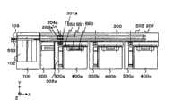
以下说明实际的检体齿条流程的一个实施例。图18、图19是由取样单元100、齿条输送单元200、三台缓冲单元300a、300b、300c、功能模块400a、400b、400c、以及附属模块500构成的系统的简图。An example of an actual specimen rack flow will be described below. 18 and 19 are schematic diagrams of a system composed of a
作为一例,利用图18说明检体齿条需要进行在功能模块400a和附属模块500的处理,而且各功能模块和附属模块的负载中400a最小且不需要进行自动重检的场合。As an example, the sample rack needs to be processed by the
在该场合,就投入到取样单元100的检体齿条而言,如前面所述那样依据齿条ID、检体ID的信息确定应该处理的项目。此时,控制部进行负载较小的功能模块的检索和在该功能模块可处理的项目的检索。基于负载信息最初挑选功能模块400a,由于该齿条需要在功能模块400a进行处理从而确定400a为输送目的地。按照该确定,检体齿条经由齿条输送单元200的进给通道201,并利用缓冲单元300a的转装机构从齿条输入位置203a向缓冲单元内移动。In this case, regarding the sample rack loaded into the
此时,若功能模块400a处于能够立即进行所转装的检体齿条的处理的状态、即功能模块400a内的缓冲器403a为未装满的状态,则检体齿条输送到功能模块400a。另外,在功能模块400a处于不能对所转装的检体齿条立即进行处理的状态的场合,检体齿条输送到缓冲部302a待机。At this time, if the
上述检体齿条移动到缓冲单元300a之后,从取样单元开始对于下一个检体齿条同样地进行输送路径的确定。在下一个检体齿条也将功能模块400a作为输送目的地而确定的场合,在该时刻若缓冲单元300a和功能模块400a、附属模块500、以及在其间的输送路上的检体齿条数的总和不足缓冲单元300a的缓冲部302a的槽数,则继续进行向缓冲单元300a的检体齿条输入,检体齿条在缓冲部302a的空槽中待机。另外,在上述检体齿条数的总和达到了缓冲部槽数的场合,检体齿条在取样单元待机直到进行从缓冲单元300a向齿条输送单元200的检体齿条的输出为止。After the sample rack moves to the
使之在缓冲部302a待机的检体齿条在功能模块400a的缓冲器403a中出现空位的时刻输送到功能模块,依次进行处理,并输出到缓冲单元300a的模块齿条输出位置404a。在该时刻对于该齿条确定下一个输送路径。若将此时的各功能模块以及附属模块的负载状态设为按400b、500、400c的顺序变小,则控制部挑选功能模块400b,但由于该齿条不需要在功能模块400b的处理,因此,控制部再次挑选负载较小的附属模块500。该齿条由于需要进行在附属模块500的处理,因此,确定附属模块500为下一个输送目的地。The sample rack waiting in the
此时,齿条在附属模块500能够立即处理该齿条的场合直接输送到附属模块500,若为不能立即进行处理的状态则暂时在缓冲部302a待机并在处于能够进行处理的状态后输送到附属模块500。At this time, the rack is directly transported to the sub-module 500 if the sub-module 500 can process the rack immediately.
结束了在附属模块500的处理的该齿条输出到附属模块齿条输出位置503。这里,再次进行下一个输送路经的确定,而对于该齿条来讲所需处理已全部结束,因此,确定取样单元100的容纳部102为输送目的地。基于该确定,缓冲单元300a利用转装机构使齿条移动到齿条输送单元200的返回通道202的齿条输入输出位置204a,齿条输送单元200将该齿条容纳到容纳部。The rack that has finished processing in the
作为另一例,利用图19说明检体齿条需要进行在功能模块400a、400b、400c的处理,而且各功能模块和附属模块的负载中400c最小且在功能模块400b需要进行自动重检的场合。As another example, use FIG. 19 to describe the case where the sample rack needs to be processed by the
投入到取样单元100的检体齿条,执行图17的流程,最初将负载较低的功能模块400c确定为输送目的地。该检体齿条由齿条输送单元200的进给通道201移动到齿条输入输出位置203c,并借助于缓冲单元300c进行在功能模块400c的处理,结束后,在模块齿条输出位置404c确定下一个输送路径。The sample rack loaded into the
若此刻的各功能模块的负载在400a和400b相同,则检体齿条的输送目的地确定为距功能模块400c的移动距离较小的功能模块400b。因此,该齿条借助于缓冲单元300c输出到齿条输送单元200的返回通道202的齿条输入输出位置204c,并经由返回通道202向缓冲单元300b的齿条输入输出位置204b移动,借助于缓冲单元300b在功能模块400b确定下一个输送路经。处理结束后,在模块齿条输出位置404b确定下一个输送路径。If the loads of the functional modules at this moment are the same at 400a and 400b, the transport destination of the sample rack is determined to be the
若此刻的各功能模块的负载中400a较低,输送目的地同样确定为400a,该检体齿条借助于缓冲单元300b输出到齿条输送单元200的返回通道202的齿条输入输出位置204b,并经由返回通道202向缓冲单元300a的齿条输入输出位置204a移动,借助于缓冲单元300a在功能模块400a进行处理。处理结束后,在模块齿条输出位置404a确定下一个输送路径。If the
此刻同样地执行图17的流程,进行输送目的地的挑选。此时,在功能模块400b的初次测定结果已出且判明为有必要进行重检的场合,功能模块400b作为输送目的地确定。另外,在初次测定结果未出且要否进行重检不明确的场合,在缓冲单元300a的缓冲部302a待机。At this time, the flow in FIG. 17 is similarly executed to select a delivery destination. At this time, when the first measurement result of the
在进行重检的场合,该齿条借助于缓冲单元300a输出到齿条输送单元200的进给通道201的齿条输入输出位置203a,并经由进给通道201移动到缓冲单元300b的齿条输入输出位置203b后,在功能模块400b进行重检处理。处理结束后,在模块齿条输出位置404b确定下一个输送路径。In the case of re-inspection, the rack is output to the rack input and
虽然这里也同样地执行图17的流程,进行输送目的地的挑选,但对于该齿条的处理已全部结束,因而确定取样单元100的容纳部102为输送目的地。于是,该齿条借助于缓冲单元300b输出到齿条输送单元200的返回通道202的齿条输入输出位置204b,并经由返回通道202容纳到取样单元100的容纳部102。Here, too, the flow in FIG. 17 is executed to select the delivery destination, but all processing for the rack has been completed, so the
另外,在不进行重检的场合,在缓冲单元300a的缓冲部302a待机的该齿条的输送目的地确定为取样单元100的容纳部102,同样地输出到齿条输送单元200的返回通道202的齿条输入输出位置204b,并经由返回通道202容纳到取样单元100的容纳部102。In addition, when re-inspection is not performed, the transport destination of the rack waiting in the
下面利用图20说明投入了紧急检体的场合的处理,这里,简便起见,对于紧急检体仅在功能模块400a需要进行处理的场合进行说明。Next, using FIG. 20 , the processing when emergency samples are put in will be described. Here, for the sake of brevity, the emergency samples will be described only when the
投入到取样单元100的紧急检体投入部109的紧急检体齿条553在读取了ID后,确定功能模块400a为输送目的地,从缓冲单元300a的齿条输入输出位置203a输入到缓冲单元300a的齿条输入输出待机位置301a。在缓冲单元300a以及功能模块400a中,在已知紧急检体将输送过来时,开始进行将处在输送路径中的一般检体齿条550、551、552向缓冲部302a移动的动作。紧急检体齿条553一旦到功能模块400a为止的输送路径可使用就立即输送到功能模块400a并进行处理。另一方面,暂时退避到缓冲部302a的一般检体齿条550、551、552一旦紧急检体齿条553向功能模块400a输送就立即再次向功能模块400a输送,重新开始进行处理。处理结束的紧急检体齿条553按照前面所述的流程容纳到容纳部102。After the
Claims (8)
Translated fromChineseApplications Claiming Priority (3)
| Application Number | Priority Date | Filing Date | Title |
|---|---|---|---|
| JP2007-331312 | 2007-12-25 | ||
| JP2007331312AJP5049769B2 (en) | 2007-12-25 | 2007-12-25 | Automatic analyzer and sample processing system |
| JP2007331312 | 2007-12-25 |
Related Child Applications (1)
| Application Number | Title | Priority Date | Filing Date |
|---|---|---|---|
| CN201210457573.8ADivisionCN102981006B (en) | 2007-12-25 | 2008-12-24 | Automatic analzyer and sample-processing system |
Publications (2)
| Publication Number | Publication Date |
|---|---|
| CN101470125A CN101470125A (en) | 2009-07-01 |
| CN101470125Btrue CN101470125B (en) | 2012-12-12 |
Family
ID=40513939
Family Applications (2)
| Application Number | Title | Priority Date | Filing Date |
|---|---|---|---|
| CN2008101844562AActiveCN101470125B (en) | 2007-12-25 | 2008-12-24 | Automatic analysis device and sample processing system |
| CN201210457573.8AActiveCN102981006B (en) | 2007-12-25 | 2008-12-24 | Automatic analzyer and sample-processing system |
Family Applications After (1)
| Application Number | Title | Priority Date | Filing Date |
|---|---|---|---|
| CN201210457573.8AActiveCN102981006B (en) | 2007-12-25 | 2008-12-24 | Automatic analzyer and sample-processing system |
Country Status (4)
| Country | Link |
|---|---|
| US (4) | US8252233B2 (en) |
| EP (1) | EP2075583B1 (en) |
| JP (1) | JP5049769B2 (en) |
| CN (2) | CN101470125B (en) |
Families Citing this family (75)
| Publication number | Priority date | Publication date | Assignee | Title |
|---|---|---|---|---|
| JP3133890U (en)* | 2007-05-16 | 2007-07-26 | 株式会社日立ハイテクノロジーズ | Sample processing system |
| JP5049769B2 (en)* | 2007-12-25 | 2012-10-17 | 株式会社日立ハイテクノロジーズ | Automatic analyzer and sample processing system |
| JP5213481B2 (en)* | 2008-02-29 | 2013-06-19 | アークレイ株式会社 | Analysis device and analysis system |
| EP2148206B1 (en)* | 2008-07-25 | 2015-11-18 | F.Hoffmann-La Roche Ag | A laboratory system for handling sample tube racks, an alignmemt element for sample tube racks and a rack tray receiver assembly |
| EP2330425B1 (en)* | 2008-09-16 | 2020-04-08 | Hitachi High-Technologies Corporation | Sample processing system |
| JP5142976B2 (en) | 2008-12-25 | 2013-02-13 | 株式会社日立ハイテクノロジーズ | Automatic analyzer |
| EP2299282B1 (en)* | 2009-09-16 | 2020-08-26 | Sysmex Corporation | Sample processing apparatus, sample transporting device, and sample rack transporting method |
| JP5439107B2 (en)* | 2009-09-30 | 2014-03-12 | シスメックス株式会社 | Rack collection unit |
| JP5342389B2 (en)* | 2009-09-25 | 2013-11-13 | シスメックス株式会社 | Specimen processing apparatus and specimen transport apparatus |
| JP2011064537A (en)* | 2009-09-16 | 2011-03-31 | Sysmex Corp | Specimen processing device |
| EP2485058B1 (en)* | 2009-09-30 | 2019-07-03 | Hitachi High-Technologies Corporation | Automated specimen testing system |
| US9291633B2 (en)* | 2009-09-30 | 2016-03-22 | Hitachi High-Technologies Corporation | Automated sample processing system |
| JP5372734B2 (en)* | 2009-12-28 | 2013-12-18 | シスメックス株式会社 | Sample processing system and sample transport unit |
| WO2011093442A1 (en) | 2010-01-28 | 2011-08-04 | 株式会社日立ハイテクノロジーズ | Automatic analyzing system |
| JP5372821B2 (en)* | 2010-03-25 | 2013-12-18 | モレックス インコーポレイテド | BOD automatic measuring device |
| CN102221624B (en)* | 2010-04-14 | 2014-02-12 | 深圳迈瑞生物医疗电子股份有限公司 | Sample rack delivery system and biochemical analyzer |
| JP5513259B2 (en)* | 2010-05-27 | 2014-06-04 | シスメックス株式会社 | Sample processing apparatus and rack transport method |
| EP2478962A1 (en)* | 2011-01-24 | 2012-07-25 | Miltenyi Biotec GmbH | Heating device for cylindrical laboratory vessels |
| CN103748472B (en)* | 2011-09-05 | 2016-08-17 | 株式会社日立高新技术 | Automatic analysis device |
| JP5815362B2 (en) | 2011-10-17 | 2015-11-17 | シスメックス株式会社 | Glucose tolerance analyzer, glucose tolerance analysis system and computer program |
| CN104105969B (en)* | 2011-11-07 | 2016-10-12 | 贝克曼考尔特公司 | Centrifuge system and workflow |
| BR112014010955A2 (en) | 2011-11-07 | 2017-06-06 | Beckman Coulter Inc | system and method for processing samples |
| JP6042130B2 (en)* | 2012-07-31 | 2016-12-14 | シスメックス株式会社 | Specimen transfer device, specimen processing system, and specimen transfer method |
| JP6169337B2 (en)* | 2012-09-03 | 2017-07-26 | 株式会社日立ハイテクノロジーズ | Sample test automation system and sample transport method |
| AU2013202805B2 (en)* | 2013-03-14 | 2015-07-16 | Gen-Probe Incorporated | System and method for extending the capabilities of a diagnostic analyzer |
| CN107831324B (en)* | 2013-03-15 | 2021-11-19 | 雅培制药有限公司 | Automated diagnostic analyzer with rear accessible track system and related methods |
| US9632103B2 (en) | 2013-03-15 | 2017-04-25 | Abbott Laboraties | Linear track diagnostic analyzer |
| US9513303B2 (en) | 2013-03-15 | 2016-12-06 | Abbott Laboratories | Light-blocking system for a diagnostic analyzer |
| US9993820B2 (en) | 2013-03-15 | 2018-06-12 | Abbott Laboratories | Automated reagent manager of a diagnostic analyzer system |
| CN105229473B (en)* | 2013-06-17 | 2017-08-18 | 株式会社日立高新技术 | Automatic analysis device |
| CN104569461B (en)* | 2013-10-15 | 2016-08-10 | 深圳迈瑞生物医疗电子股份有限公司 | Sample rack vehicle and streamline and Transfer method |
| US10150620B2 (en) | 2013-11-01 | 2018-12-11 | Hitachi High-Technologies Corporation | Sample transfer device and sample processing system |
| ES2882303T3 (en) | 2013-12-10 | 2021-12-01 | Hoffmann La Roche | Tube rack transfer device and diagnostic instrument |
| CN103884854B (en)* | 2014-04-01 | 2016-01-20 | 重庆科斯迈生物科技有限公司 | Sample system of chemiluminescence immunity analyzer |
| CN103884857B (en)* | 2014-04-01 | 2015-09-30 | 重庆科斯迈生物科技有限公司 | Chemical illumination immunity analysis instrument sample system |
| EP3163309B1 (en)* | 2014-06-26 | 2021-07-28 | Hitachi High-Tech Corporation | Automatic analytical apparatus |
| EP3176587B1 (en)* | 2014-07-31 | 2020-11-04 | Hitachi High-Tech Corporation | Automated analyzer |
| WO2016130964A1 (en) | 2015-02-13 | 2016-08-18 | Abbott Laboratories | Decapping and capping apparatus, systems and methods for use in diagnostic analyzers |
| US10551398B2 (en)* | 2015-04-27 | 2020-02-04 | Hitachi High-Technologies Corporation | Specimen container inclination correction mechanism, and method for controlling same |
| EP3314269A4 (en) | 2015-06-26 | 2019-01-23 | Abbott Laboratories | Reaction vessel exchanger device for a diagnostic analyzer |
| JP6465775B2 (en)* | 2015-08-25 | 2019-02-06 | 株式会社日立ハイテクノロジーズ | Sample processing system |
| WO2017043196A1 (en)* | 2015-09-11 | 2017-03-16 | 株式会社 日立ハイテクノロジーズ | Automated analyzer |
| CN105235961A (en)* | 2015-09-16 | 2016-01-13 | 上海创司杰医疗科技有限公司 | Blood collection tube storage and grabbing device with buffering function |
| JP6573547B2 (en)* | 2015-12-25 | 2019-09-11 | 日本電子株式会社 | Sample rack transport apparatus, automatic analysis system, and sample rack recovery method for sample rack transport apparatus |
| FR3047082B1 (en)* | 2016-01-25 | 2018-02-16 | Arteion | SUPPLY CONVEYING SYSTEM FOR CONTAINERS OF BIOLOGICAL LIQUID SAMPLES, AND AUTOMATIC ANALYSIS SYSTEM COMPRISING SUCH A CONVEYING SYSTEM |
| EP3214451A1 (en) | 2016-03-03 | 2017-09-06 | Roche Diagnostics GmbH | Sample carrier handling device |
| KR102650702B1 (en)* | 2016-03-04 | 2024-03-25 | (주)테크윙 | Cart of supplying tray for supplying electronic components and handler of processing electronic components |
| CN113917168B (en)* | 2016-04-15 | 2025-10-03 | 深圳迈瑞生物医疗电子股份有限公司 | Sample rack transport device, sample analysis equipment and sample analysis system |
| CN105929187B (en)* | 2016-04-15 | 2018-01-02 | 迈克医疗电子有限公司 | Specimen conveying system, pattern detection instrument, sample conveyance control method and device |
| CN106771283B (en)* | 2016-12-19 | 2018-08-10 | 宁波美康盛德生物科技有限公司 | Biochemical Analyzer transport system |
| US11486887B2 (en) | 2016-12-19 | 2022-11-01 | Hitachi High-Tech Corporation | Automated analyzer |
| IT201600130628A1 (en)* | 2016-12-23 | 2018-06-23 | Inpeco Holding Ltd | Liquid handling equipment |
| FR3061959B1 (en)* | 2017-01-19 | 2019-05-31 | Horiba Abx Sas | BIOLOGICAL ANALYSIS SYSTEM |
| FR3061960B1 (en)* | 2017-01-19 | 2019-05-31 | Horiba Abx Sas | SYSTEM OF BIOLOGICAL ANALYZES WITH TREATMENT OF SPECIFIC PORTALS |
| KR102205942B1 (en)* | 2017-01-25 | 2021-01-21 | (주)자비스 | An X-ray Investigating Apparatus Having Buffer Area and a Method by the Same |
| JP6166002B2 (en)* | 2017-01-31 | 2017-07-19 | 株式会社日立ハイテクノロジーズ | Sample processing system |
| CN110325865A (en)* | 2017-03-07 | 2019-10-11 | 株式会社日立高新技术 | Automatic analysing apparatus |
| WO2018221220A1 (en)* | 2017-06-02 | 2018-12-06 | 株式会社日立ハイテクノロジーズ | Automatic analysis device |
| CN109580970B (en)* | 2017-09-29 | 2022-07-15 | 深圳市新产业生物医学工程股份有限公司 | Sample rack loading system, loading method and chemiluminescence detector |
| CN111542742B (en) | 2017-11-27 | 2022-01-11 | 徕卡生物系统成像股份有限公司 | Slide rack determination system |
| CN109975277B (en)* | 2017-12-28 | 2024-08-13 | 深圳市新产业生物医学工程股份有限公司 | Chemiluminescent detector and detection method thereof |
| EP3674714B1 (en)* | 2018-02-02 | 2025-10-08 | Hitachi High-Tech Corporation | Specimen inspection automation system for managing empty specimen carrier |
| CN110398601A (en)* | 2018-04-25 | 2019-11-01 | 深圳迈瑞生物医疗电子股份有限公司 | A kind of sample analysis system and a kind of sample analysis system control method |
| CN109212242B (en)* | 2018-08-23 | 2022-02-18 | 迪瑞医疗科技股份有限公司 | Sample rack carrying and transporting device and sample rack transporting method |
| CN109911540A (en)* | 2019-01-29 | 2019-06-21 | 迈克医疗电子有限公司 | A kind of dispatching method and device of pipelining equipment |
| CN110146717A (en)* | 2019-06-05 | 2019-08-20 | 深圳市亚辉龙生物科技股份有限公司 | Analyzer automatic docking method, apparatus, computer equipment and storage medium |
| CN114846333A (en)* | 2020-01-30 | 2022-08-02 | 株式会社日立高新技术 | automatic analysis system |
| CN113879828B (en)* | 2020-07-01 | 2025-04-04 | 前海瑞智捷自动化科技(深圳)有限公司 | Carrier tray buffer |
| CN111904438B (en)* | 2020-09-04 | 2021-06-04 | 山东省血液中心 | Automatic blood sampling and blood detection integrated machine and blood sampling method |
| JP7348408B2 (en) | 2020-09-29 | 2023-09-20 | 株式会社日立ハイテク | automatic analyzer |
| CN114487451A (en)* | 2020-11-13 | 2022-05-13 | 深圳市帝迈生物技术有限公司 | Sample introduction mechanism, sample introduction method and sample analyzer |
| CN113804904A (en)* | 2021-09-13 | 2021-12-17 | 广州蓝勃生物科技有限公司 | Sample reinspection control method and device, computer equipment and storage medium |
| CN114264829A (en)* | 2021-11-09 | 2022-04-01 | 北京胡曼智造科技有限责任公司 | A sample rack connecting rail conveying device |
| JP2023075993A (en)* | 2021-11-22 | 2023-06-01 | 株式会社日立製作所 | Rack gripping device |
| CN114291563B (en)* | 2021-12-31 | 2023-07-25 | 南京国科精准医学科技有限公司 | A sample buffer device |
Citations (3)
| Publication number | Priority date | Publication date | Assignee | Title |
|---|---|---|---|---|
| US6080364A (en)* | 1997-04-10 | 2000-06-27 | Hitachi, Ltd. | Automatic analyzer and support system therefor |
| CN1673742A (en)* | 2004-03-24 | 2005-09-28 | 株式会社Ids | Blood sample conveyor-analyzer system |
| CN1683221A (en)* | 2004-04-12 | 2005-10-19 | 株式会社Ids | Sample transport system with mobile equipment |
Family Cites Families (31)
| Publication number | Priority date | Publication date | Assignee | Title |
|---|---|---|---|---|
| DE3246274C2 (en)* | 1981-12-14 | 1985-05-30 | Olympus Optical Co., Ltd., Tokio/Tokyo | Analyzer working with immunological agglutination reaction |
| GB9020352D0 (en)* | 1990-09-18 | 1990-10-31 | Anagen Ltd | Assay or reaction apparatus |
| JP2947917B2 (en)* | 1990-11-05 | 1999-09-13 | 株式会社日立製作所 | Laboratory test system |
| JPH06207943A (en) | 1993-01-11 | 1994-07-26 | Toshiba Corp | Automatic analyzer |
| US5623415A (en) | 1995-02-16 | 1997-04-22 | Smithkline Beecham Corporation | Automated sampling and testing of biological materials |
| CN1099084C (en)* | 1995-02-16 | 2003-01-15 | 史密丝克莱恩比彻姆公司 | Appts. and process |
| JP2939162B2 (en)* | 1995-08-16 | 1999-08-25 | 株式会社エイアンドティー | Processing equipment in sample transport system |
| JPH09211005A (en) | 1996-01-30 | 1997-08-15 | Olympus Optical Co Ltd | Specimen automatic feed apparatus for examination |
| JP2988362B2 (en) | 1996-03-11 | 1999-12-13 | 株式会社日立製作所 | Multi-sample analysis system |
| JP3031237B2 (en)* | 1996-04-10 | 2000-04-10 | 株式会社日立製作所 | Method of transporting sample rack and automatic analyzer for transporting sample rack |
| JP3317851B2 (en)* | 1996-07-05 | 2002-08-26 | 株式会社日立製作所 | Multi-item automatic analyzer |
| WO1998018009A1 (en)* | 1996-10-23 | 1998-04-30 | Hitachi, Ltd. | Biochemical analyzer |
| JP3336894B2 (en)* | 1997-01-29 | 2002-10-21 | 株式会社日立製作所 | Automatic analyzer |
| DE69840189D1 (en)* | 1997-09-11 | 2008-12-18 | Hitachi Ltd | Sample handling system for automatic analyzers |
| JP3589020B2 (en) | 1998-04-17 | 2004-11-17 | 株式会社日立製作所 | Sample processing system |
| JP3609945B2 (en) | 1998-08-28 | 2005-01-12 | 株式会社日立製作所 | Automatic analysis method and apparatus |
| DE69942220D1 (en)* | 1998-07-27 | 2010-05-20 | Hitachi Ltd | Method for handling body fluid samples and analyzer. which uses these |
| JP2000088856A (en)* | 1998-09-11 | 2000-03-31 | Aloka Co Ltd | Specimen conveying system |
| JP3284196B2 (en) | 1999-01-14 | 2002-05-20 | 理学電機工業株式会社 | Sample attachment / detachment apparatus and X-ray fluorescence analyzer having the same |
| JP2001242179A (en) | 2000-02-28 | 2001-09-07 | Hitachi Ltd | Sample transport system |
| CA2417541A1 (en)* | 2002-01-25 | 2003-07-25 | Hansjoerg Werner Haas | Modular robotic system for sample processing |
| JP3931150B2 (en)* | 2003-03-19 | 2007-06-13 | 株式会社日立ハイテクノロジーズ | Automatic analyzer |
| JP2004317269A (en)* | 2003-04-16 | 2004-11-11 | Hitachi High-Technologies Corp | Automatic analyzer |
| US7850914B2 (en)* | 2004-03-05 | 2010-12-14 | Beckman Coulter, Inc. | Specimen-transport module for a multi-instrument clinical workcell |
| US7448487B2 (en)* | 2005-03-28 | 2008-11-11 | Sysmex Corporation | Transporting apparatus |
| JP2008058123A (en)* | 2006-08-31 | 2008-03-13 | Hitachi High-Technologies Corp | Automatic analyzer |
| JP4336360B2 (en)* | 2006-09-20 | 2009-09-30 | 株式会社アイディエス | Sample pretreatment transport device |
| JP2008281453A (en)* | 2007-05-11 | 2008-11-20 | Hitachi High-Technologies Corp | Automatic analysis system |
| JP3133890U (en)* | 2007-05-16 | 2007-07-26 | 株式会社日立ハイテクノロジーズ | Sample processing system |
| JP5049769B2 (en)* | 2007-12-25 | 2012-10-17 | 株式会社日立ハイテクノロジーズ | Automatic analyzer and sample processing system |
| EP2330425B1 (en)* | 2008-09-16 | 2020-04-08 | Hitachi High-Technologies Corporation | Sample processing system |
- 2007
- 2007-12-25JPJP2007331312Apatent/JP5049769B2/enactiveActive
- 2008
- 2008-12-23EPEP08022420.7Apatent/EP2075583B1/enactiveActive
- 2008-12-23USUS12/342,162patent/US8252233B2/enactiveActive
- 2008-12-24CNCN2008101844562Apatent/CN101470125B/enactiveActive
- 2008-12-24CNCN201210457573.8Apatent/CN102981006B/enactiveActive
- 2012
- 2012-07-27USUS13/560,114patent/US9229019B2/enactiveActive
- 2015
- 2015-12-02USUS14/956,663patent/US10094846B2/enactiveActive
- 2018
- 2018-07-06USUS16/028,538patent/US11391750B2/enactiveActive
Patent Citations (3)
| Publication number | Priority date | Publication date | Assignee | Title |
|---|---|---|---|---|
| US6080364A (en)* | 1997-04-10 | 2000-06-27 | Hitachi, Ltd. | Automatic analyzer and support system therefor |
| CN1673742A (en)* | 2004-03-24 | 2005-09-28 | 株式会社Ids | Blood sample conveyor-analyzer system |
| CN1683221A (en)* | 2004-04-12 | 2005-10-19 | 株式会社Ids | Sample transport system with mobile equipment |
Also Published As
| Publication number | Publication date |
|---|---|
| JP2009150859A (en) | 2009-07-09 |
| US9229019B2 (en) | 2016-01-05 |
| EP2075583A2 (en) | 2009-07-01 |
| US10094846B2 (en) | 2018-10-09 |
| CN102981006B (en) | 2014-06-18 |
| EP2075583B1 (en) | 2021-03-31 |
| US11391750B2 (en) | 2022-07-19 |
| US8252233B2 (en) | 2012-08-28 |
| EP2075583A3 (en) | 2014-05-14 |
| CN101470125A (en) | 2009-07-01 |
| US20090162247A1 (en) | 2009-06-25 |
| US20160084864A1 (en) | 2016-03-24 |
| JP5049769B2 (en) | 2012-10-17 |
| US20120294764A1 (en) | 2012-11-22 |
| CN102981006A (en) | 2013-03-20 |
| US20180313862A1 (en) | 2018-11-01 |
Similar Documents
| Publication | Publication Date | Title |
|---|---|---|
| CN101470125B (en) | Automatic analysis device and sample processing system | |
| JP6230915B2 (en) | Sample transfer device and system | |
| EP2330425B1 (en) | Sample processing system | |
| EP2142907B1 (en) | Programmable random access sample handler for use within an automated laboratory system | |
| JP6871742B2 (en) | Methods and devices for transferring sample tubes between laboratory automation systems and sample storage systems | |
| JP5648116B2 (en) | Sample processing system | |
| JP2001074754A (en) | Automatic analyzer | |
| JP4469963B2 (en) | Sample transport device | |
| JP6165958B2 (en) | Sample processing system | |
| JP2001153875A (en) | Autoanalyzer | |
| JP6069459B2 (en) | Sample processing system, functional module, and method for transporting sample rack of sample processing system | |
| JP6166001B2 (en) | Sample processing system | |
| JP5836468B2 (en) | Sample processing system | |
| JP6166002B2 (en) | Sample processing system | |
| JP5417498B2 (en) | Sample processing system | |
| JP6374058B2 (en) | Sample processing system | |
| JP6638029B2 (en) | Sample processing system | |
| US20230228781A1 (en) | Container transfer method and container transfer apparatus | |
| CN119716098A (en) | Sample analysis system |
Legal Events
| Date | Code | Title | Description |
|---|---|---|---|
| C06 | Publication | ||
| PB01 | Publication | ||
| C10 | Entry into substantive examination | ||
| SE01 | Entry into force of request for substantive examination | ||
| C14 | Grant of patent or utility model | ||
| GR01 | Patent grant |