CN101470083B - New folding arm mechanism for vehicle-mounted radiation imaging system - Google Patents
New folding arm mechanism for vehicle-mounted radiation imaging systemDownload PDFInfo
- Publication number
- CN101470083B CN101470083BCN2007103043757ACN200710304375ACN101470083BCN 101470083 BCN101470083 BCN 101470083BCN 2007103043757 ACN2007103043757 ACN 2007103043757ACN 200710304375 ACN200710304375 ACN 200710304375ACN 101470083 BCN101470083 BCN 101470083B
- Authority
- CN
- China
- Prior art keywords
- arm
- vehicle
- frame
- arm mechanism
- folding arm
- Prior art date
- Legal status (The legal status is an assumption and is not a legal conclusion. Google has not performed a legal analysis and makes no representation as to the accuracy of the status listed.)
- Active
Links
Images


Classifications
- E—FIXED CONSTRUCTIONS
- E05—LOCKS; KEYS; WINDOW OR DOOR FITTINGS; SAFES
- E05D—HINGES OR SUSPENSION DEVICES FOR DOORS, WINDOWS OR WINGS
- E05D5/00—Construction of single parts, e.g. the parts for attachment
- E05D5/02—Parts for attachment, e.g. flaps
Landscapes
- Engineering & Computer Science (AREA)
- Mechanical Engineering (AREA)
- Body Structure For Vehicles (AREA)
- Fittings On The Vehicle Exterior For Carrying Loads, And Devices For Holding Or Mounting Articles (AREA)
- Aiming, Guidance, Guns With A Light Source, Armor, Camouflage, And Targets (AREA)
Abstract
Translated fromChinese
Description
Translated fromChinese技术领域technical field
本发明涉及辐射检测技术领域,特别是涉及一种用于车载式辐射成像系统的折臂机构。The invention relates to the technical field of radiation detection, in particular to a folding arm mechanism for a vehicle-mounted radiation imaging system.
背景技术Background technique
安全检查在反对恐怖主义、打击贩毒走私等领域具有十分重要的意义。2001年美国911事件之后,人们对民用航空的安全检查越来越重视。同时随着打击贩毒走私的深入展开,对航空集装箱、铁路行李箱等的检查要求也越来越高。Security inspection is of great significance in the fields of anti-terrorism and combating drug trafficking and smuggling. After the September 11 incident in the United States in 2001, people paid more and more attention to the safety inspection of civil aviation. At the same time, with the deepening of the fight against drug trafficking and smuggling, the inspection requirements for air containers and railway luggage are getting higher and higher.
与本发明最接近的现有技术的车载式成像系统是由本申请人正在使用的车载式成像系统。参照附图8,9,10,11A,11B和11C,该车载式成像系统一般包括承载成像系统的车辆和折臂机构44,该车辆包括车身、驾驶室42,该车身沿车辆行驶方向分成发电机舱41和检查系统控制舱40,所述折臂机构44在折叠状态时被紧凑地置于该车身顶部上以便于由车辆携带和运输到需要使用的地方,其中折臂机构的竖探测臂位于该设备室上面,所述设备室一般没有空间的要求因此可以做得较低从而可以在其顶部上放置折叠后的竖探测臂。折叠后的竖探测臂一般位于所述折臂机构44的主臂架的侧面上而且竖探测臂的最低点低于主臂架的最低点。在现有技术中,主臂架的回转轴承部位位于发电机舱上,该回转轴承部位从主臂架向下倾斜延伸而低于发电机舱的顶部最高点所在的平面,因此该发电机舱的顶部不得不做成阶梯形形状,即有两个平行的处于不同高度的平面。因此在现有技术的这样的车载式成像系统中,原折臂机构中的回转点造成了压舱,而且相对较大的副臂架更加增大了占用舱体的空间。这样的发电机舱的生产加工较复杂因而增加了生产成本。The closest prior art vehicular imaging system to the present invention is the vehicular imaging system being used by the applicant. Referring to accompanying
在现有技术中,发电机舱靠近驾驶室42。加速器位于竖探测臂展开后与主臂架形成的通道位置以便进行辐射成像检测,因此控制舱在现有技术中距离该加速器靶点相对较近,如果将发电机舱与控制舱位置对调则可以降低辐射所带来的影响。因而希望将人员所在的控制舱移到此位置上以增加对人员的保护。在现有技术中,因发电机舱并不是人员操作的区域,因此发电机舱塌下一块的结构除了生产较复杂外并无任何其他问题。但是现有技术的这种设计为达到一定的辐射防护水平,必然导致控制舱在检测状态时距离加速器靶点较近因而该控制舱壁和顶部需要较多的辐射防护材料。因而增加了该车载系统的载重,降低了该车载系统对各国车辆限重法规的适应性,同时也增加了生产成本。In the prior art, the generator compartment is located close to the
现有技术的折臂机构在需要使用时,首先需要将折叠的折臂机构平行于地面向车身一侧旋转大致90度使得该折臂机构大致垂直于车辆的行进方向,然后将竖探测臂向下旋转大约90度从而该竖探测臂与主臂架大致垂直并且大致垂直于地面,如图8所示,此时,折臂机构展开,竖探测臂在车身的一侧,通过一铰接机构悬置在主臂架上从而形成了用于待检测的物体通过的检测通道区域。设备舱旋转移向车身的另一侧,在控制舱中工作人员进行相应的控制操作。When the folding arm mechanism of the prior art needs to be used, it is first necessary to rotate the folded arm mechanism parallel to the ground to the side of the vehicle body by approximately 90 degrees so that the folding arm mechanism is approximately perpendicular to the direction of travel of the vehicle, and then the vertical detection arm is Rotate down about 90 degrees so that the vertical detection arm is approximately perpendicular to the main boom frame and the ground, as shown in Figure 8. It is placed on the main boom to form a detection channel area for the object to be detected to pass through. The equipment cabin rotates and moves to the other side of the vehicle body, and the staff in the control cabin performs corresponding control operations.
发明内容Contents of the invention
本发明给出一种用于车载式辐射成像系统的折臂机构,其可以应用于这样的车载式辐射成像系统:发电机舱和控制舱对调,以便减少辐射防护材料的使用,同时保护工作人员不受辐射的危害。同时该折臂机构还带来了下述的优点:避免因上述的压舱导致的人员活动空间受限制,使得人员在控制舱中可以舒适的工作。The invention provides a folding arm mechanism for a vehicle-mounted radiation imaging system, which can be applied to such a vehicle-mounted radiation imaging system: the generator cabin and the control cabin are reversed, so as to reduce the use of radiation protection materials and protect workers from Hazards from radiation. Simultaneously, the folding arm mechanism also brings the following advantages: avoiding the limitation of the personnel activity space caused by the above-mentioned ballast cabin, so that the personnel can work comfortably in the control cabin.
另外,本领域技术人员已知:车载式检查系统的重量一直是制约其发展的重要指标,其相对较轻的车重轴荷将能适应更多国家的法规要求。通过车载式检查系统控制舱的前移,与发电机舱调换位置,从而使得控制舱上防护材料的用量大大降低,进而减轻重量。但是因为存在主臂架压舱的问题,因此控制舱前移后其顶部的一部分将必须要向下塌陷,导致了人员活动的空间被减小并且增大了舱体加工的难度。这个缺点也被本发明的折臂机构克服了。In addition, those skilled in the art know that the weight of the vehicle-mounted inspection system has always been an important indicator restricting its development, and its relatively light vehicle weight and axle load will be able to meet the legal requirements of more countries. Through the forward movement of the control cabin of the vehicle-mounted inspection system and the exchange of positions with the generator cabin, the amount of protective materials on the control cabin is greatly reduced, thereby reducing the weight. However, because of the main boom ballast problem, a part of the top of the control cabin must collapse downward after the control cabin moves forward, which reduces the space for personnel activities and increases the difficulty of cabin processing. This shortcoming is also overcome by the folding arm mechanism of the present invention.
本发明的折臂机构在保证控制舱空间尺寸不变的条件下实现控制舱前置,而且不用使舱顶的一部分下陷,降低了原设备舱体加工的难度。The folding arm mechanism of the present invention realizes the front control of the control cabin under the condition that the space size of the control cabin remains unchanged, and does not need to sink a part of the cabin roof, which reduces the difficulty of processing the original equipment cabin.
综上所述本发明的目的在于针对上述现有技术中存在的不足,提供一种应用于车载式成像系统的改进的折臂机构,该折臂机构使得主臂架的铰接部分位于控制舱顶部的较高平面之上,从而增大了人员活动空间,为工作人员提供较为舒适的环境,减小了舱体的加工成本和难度,因为该折臂机构允许控制舱在不减少空间尺寸的条件下实现与发电机舱的位置对调从而实现了控制舱体上的辐射防护材料大大降低,进而减轻了车载重量。To sum up, the purpose of the present invention is to address the shortcomings in the above-mentioned prior art and provide an improved folding arm mechanism applied to the vehicle-mounted imaging system, which makes the hinged part of the main arm frame located on the top of the control cabin On the higher plane, the space for personnel activities is increased, a more comfortable environment is provided for the staff, and the processing cost and difficulty of the cabin are reduced, because the folding arm mechanism allows the control cabin to operate without reducing the size of the space. Under the realization of position exchange with the generator cabin, the radiation protection material on the control cabin is greatly reduced, thereby reducing the weight of the vehicle.
本发明的另一目的是提供一种减小了原折臂机构自身重量的新型折臂机构。Another object of the present invention is to provide a new folding arm mechanism which reduces the weight of the original folding arm mechanism.
本发明的另一个目的是提供一种用于车载式成像系统的改进的折臂机构,以一种新的方式实现竖臂的收放,并确保竖探测臂在检测状态时的姿态。Another object of the present invention is to provide an improved folding arm mechanism for a vehicle-mounted imaging system, which realizes the retraction and retraction of the vertical arm in a new way, and ensures the attitude of the vertical detection arm in the detection state.
本发明的另一目的是提供一种车载式成像系统,其具有本发明的折臂机构,其中,从车辆的前进方向看,发电机舱在控制舱后面,控制舱靠近驾驶室,控制舱的顶部和发电机舱的顶部可以是单一的平面结构。Another object of the present invention is to provide a vehicle-mounted imaging system with the folding arm mechanism of the present invention, wherein, viewed from the forward direction of the vehicle, the generator compartment is behind the control compartment, the control compartment is close to the driver's cab, and the top of the control compartment is And the top of the generator compartment can be a single plane structure.
为实现上述目的,本发明采用下述技术方案:To achieve the above object, the present invention adopts the following technical solutions:
一种应用于车载式辐射成像系统的折臂机构,该车包括在驾驶室后面的车身,车身包括发电机舱和控制舱,该折臂机构包括竖探测臂,主臂架和将竖探测臂与主臂架铰接连接的铰接机构,所述铰接机构包括:具有自由端部和与主臂架固定连接或者连成一体的固定端部的第一连接装置;与竖探测臂固定连接的第二连接装置;和将第一连接装置和第二连接装置连接使得竖探测臂可以相对主臂架旋转的中间装置,其特征在于,所述第一连接装置的底部与该主臂架的底部持平或者在该主臂架的底部之上。A folding arm mechanism applied to a vehicle-mounted radiation imaging system, the vehicle includes a body behind the driver's cab, the body includes a generator compartment and a control cabin, the folding arm mechanism includes a vertical detection arm, a main arm frame and a vertical detection arm and The hinge mechanism of the hinged connection of the main boom, the hinge mechanism includes: a first connection device having a free end and a fixed end fixedly connected or integrated with the main boom; a second connection fixedly connected with the vertical detection arm device; and an intermediate device that connects the first connection device and the second connection device so that the vertical detection arm can rotate relative to the main boom frame, it is characterized in that the bottom of the first connection device is flat with the bottom of the main boom frame or at above the bottom of the main boom.
优选地,从工作位置看,所述第一连接装置靠近该主臂架的前侧面。Preferably, viewed from the working position, the first connecting device is close to the front side of the main boom.
优选地,该中间装置包括彼此固定连接的副臂架和回转轴。Preferably, the intermediate device includes a jib frame and a rotary shaft fixedly connected to each other.
优选地,该副臂架包括连接所述竖探测臂的固定法兰和与回转轴固定连接的轴套。Preferably, the jib frame includes a fixed flange connected to the vertical detection arm and a shaft sleeve fixedly connected to the rotary shaft.
优选地,该副臂架的回转轴与固定法兰对齐的一端具有用于固定竖探测臂的凸缘和嵌入这一端的孔中的承载竖探测臂的承载轴。Preferably, one end of the sub-jib frame whose rotary shaft is aligned with the fixing flange has a flange for fixing the vertical detection arm and a bearing shaft for carrying the vertical detection arm embedded in a hole at this end.
优选地,所述轴套可分为可拆卸连接的上和下半轴套,上半轴套与副臂架主体连接或者连成一体,同时在回转轴外径上沿轴向设置与轴套的轴向长度相同的槽,使得上和下半轴套可通过紧固装置嵌在所述槽中。Preferably, the bushing can be divided into an upper half bushing and a lower half bushing that can be detachably connected, and the upper half bushing is connected or integrated with the main body of the sub-arm frame, and at the same time, it is arranged axially on the outer diameter of the rotary shaft to connect with the bushing Grooves of the same axial length, so that the upper and lower bushings can be embedded in said grooves by fastening means.
优选地,从工作状态看,所述第二连接装置为从竖探测臂上向主臂架延伸超出该竖探测臂的宽度的伸出结构使得保证检测通道尺寸。Preferably, from a working state, the second connecting device is a protruding structure extending from the vertical detection arm to the main arm frame beyond the width of the vertical detection arm so as to ensure the size of the detection channel.
一种车载式辐射成像系统,其使用了本发明的折臂机构.A vehicle-mounted radiation imaging system, which uses the folding arm mechanism of the present invention.
优选地,控制舱紧邻驾驶室,发电机舱在控制舱的后面。Preferably, the control cabin is immediately adjacent to the cockpit and the generator compartment is behind the control cabin.
优选地,控制舱的顶部为平顶结构,控制舱的空间适合工作人员操作。Preferably, the top of the control cabin is a flat top structure, and the space of the control cabin is suitable for staff to operate.
本发明具有如下有益效果:The present invention has following beneficial effect:
1、该方案使得控制舱可以在不减少空间尺寸的条件下,实现与发电机舱的位置对调,进而实现了控制舱体上的辐射防护材料的用量大大降低,从而减轻了车载重量。1. This solution enables the position of the control cabin to be swapped with the generator cabin without reducing the size of the space, thereby greatly reducing the amount of radiation protection materials on the control cabin, thereby reducing the weight of the vehicle.
2、本发明的一种优选的折臂机构自身的重量还可以较现有的折臂机构大幅降低。由图11A,11B和11C,尤其是图11C可知,现有技术的折臂机构体积较大,通过两法兰51和52连接于竖臂上,通过一个回转轴53与主臂架相连。2. The weight of a preferred folding arm mechanism of the present invention can be greatly reduced compared with the existing folding arm mechanism. From Figures 11A, 11B and 11C, especially Figure 11C, it can be seen that the folding arm mechanism in the prior art is relatively bulky, connected to the vertical arm through two
3、本发明的方案不再需要使舱顶向下塌陷,使得现有的系统的舱体施工被简化。3. The solution of the present invention no longer needs to collapse the roof of the cabin downward, so that the construction of the cabin body of the existing system is simplified.
附图说明Description of drawings
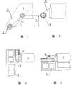
图1A和1B示出了现有技术折臂机构的铰接机构中的在主臂架上的第一连接装置;1A and 1B show the first connection device on the main boom in the hinge mechanism of the folding arm mechanism of the prior art;
图2为针对图1的第一连接装置的改进示意图;Fig. 2 is an improved schematic diagram for the first connection device of Fig. 1;
图3示出了本发明的折臂机构的工作状态;Fig. 3 shows the working state of the folding arm mechanism of the present invention;
图4示出了图3的折臂机构折起状态;Fig. 4 shows the folding state of the folding arm mechanism of Fig. 3;
图5和图6分别示出了本发明的折臂机构的铰接机构中的在竖探测臂上的第二连接装置的主视图和侧视图;Fig. 5 and Fig. 6 show respectively the front view and the side view of the second connecting device on the vertical detection arm in the hinge mechanism of the folding arm mechanism of the present invention;
图7A和7B分别示出了本发明的车载式系统处于存放运输状态的主视图和侧视图;7A and 7B respectively show a front view and a side view of the vehicle-mounted system of the present invention in a storage and transportation state;
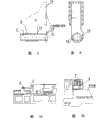
图8,图9和图10示出了现有折臂机构的工作、收起和存放运输状态的立体视图;和Fig. 8, Fig. 9 and Fig. 10 have shown the three-dimensional view of the working, stowed and stored transportation state of existing folding arm mechanism; And
图11A,11B和11C为现有折臂机构的铰接机构的主视图、侧视图和俯视图。11A, 11B and 11C are the front view, side view and top view of the hinge mechanism of the conventional folding arm mechanism.
具体实施方式Detailed ways
为使本发明提供的技术方案更加清楚和明白,以下结合具体实施例并参照附图,对本发明进行详细说明。In order to make the technical solution provided by the present invention more clear and understandable, the present invention will be described in detail below in conjunction with specific embodiments and with reference to the accompanying drawings.
首先需要明确的是,在下面提到的“前面”和“后面”都是相对于汽车的前进方向而言的。“上面”和“下面”是指在车的高度方向的相对位置。First of all, it needs to be clear that the "front" and "rear" mentioned below are relative to the forward direction of the car. "Above" and "below" refer to relative positions in the height direction of the vehicle.
另外在本说明书中,“车身左侧”和“车身右侧”是指当车辆静止时,观察者站在车头向后看时观察者的左侧和右侧。In addition, in this specification, "the left side of the vehicle body" and "the right side of the vehicle body" refer to the left and right sides of the observer when the vehicle is stationary and the observer stands at the front of the vehicle and looks backward.
如图3所示,示出了处于展开状态或者使用状态中的本发明的折臂机构,包括竖探测臂5,主臂架1以及将竖探测臂5和主臂架1铰接连接的铰接结构,所述铰接结构包括与主臂架1相连的第一连接装置和与竖探测臂5相连的第二连接装置以及将第一连接装置和第二连接装置相对转动地连接在一起的中间装置。其中第一连接装置的本体部分2平行于主臂架1的底部水平面21并且与该底部水平面21持平或者高于该底部水平面。As shown in Figure 3, the folding arm mechanism of the present invention in the expanded state or in use state is shown, including the
由图1和图2可以更清晰地看到该第一连接装置的改进,在现有技术中,第一连接装置与主臂架连成一体地向下倾斜延伸,因而导致了压舱的技术缺陷,该第一连接装置包括本体部分2和回转轴承部分3,当然也可以用其他铰接方式。The improvement of the first connection device can be seen more clearly from Fig. 1 and Fig. 2. In the prior art, the first connection device is integrally connected with the main boom frame and extends downward obliquely, thus leading to the ballast tank technology Defect, the first connecting device includes the
在图2中,本发明的第一连接装置的本体部分2平行于主臂架1,最好第一连接装置的底部在主臂架1的底部之上,本体部分2如图2所示优选为三角形板状件,或者为其他可以减少材料用量并且降低车载重量的其他形状。在图7A和7B中可以更清楚地看到该本体部分。本领域技术人员已知,主臂架1的一端可以旋转地连接到固定在汽车上的主控轴上,其另一端用于连接竖探测臂。在该另一端上,所述本体部分2尽量靠近主臂架1的底部并且靠近该主臂架1的一个侧面(所述侧面在本实施例中为展开状态下面向前面的主臂架的侧面)连接到主臂架上,回转轴承部分3设置在本体2的铰接端上(如图2所示)。由图3和图4可知,第二连接装置优选为从竖探测臂5顶部(工作状态时)伸出的竖探测臂伸出结构6,因为在回转铰轴位置上移后该竖探测臂伸出结构6可以保证检测通道的尺寸。所述竖探测臂伸出结构6可以与竖探测臂通过本领域已知的方式连接,为了降低该第二连接装置的重量和材料用量,如图3所示,该第二连接装置可以为中间镂空的形状。In Fig. 2, the
如图5和图6所示中间装置,包括副臂架4和回转轴7,所述竖探测臂伸出结构6可以通过任何已知的方式与副臂架4和竖探测臂5连成一体,只要使该伸出结构、竖探测臂和副臂架可以整体转动即可。图中所示副臂架4可分为一个带有多个螺纹孔的固定法兰13,一个过渡部分和一个轴孔部分,这3个部分成一整体。其中为了安装方便所述轴孔部分被分为与过渡部分连成一体的上半轴套,和可以与上半轴套分开的下半轴套。回转轴7优选在外径上沿轴线开一个长度等于副臂架4的轴套12的轴向长度的槽8使得所述轴套12可嵌入该槽8中。通过例如螺栓装置10的紧固装置可以把副臂架4固定到回转轴7上,从而防止副臂架4在回转轴7上的窜动。如图5所示,所述回转轴在大致与法兰13对齐的位置具有凸缘13’,以加强与竖探测臂的连接。另外该回转轴7可以为空心的,在其中在具有凸缘13’的一端插入承载轴,以进一步加强对竖探测臂的承载。中空的回转轴7与第一连接装置中的回转轴承3相连从而实现竖探测臂与主臂架1的旋转连接。从而实现为了便于运输,将竖探测臂绕该轴承3向上旋转直到置于与主臂架平行叠置并且尽可能靠近该主臂架的位置。The intermediate device shown in Figure 5 and Figure 6 includes a
由图4可知,竖探测臂受到液压油缸的控制,从而实现自动展开和保持工作状态。It can be seen from Figure 4 that the vertical detection arm is controlled by the hydraulic cylinder, so as to realize automatic deployment and maintain the working state.
使用这种折臂机构的车载式辐射成像系统优选向前面移该控制舱,紧邻驾驶室。The vehicle-mounted radiation imaging system using this folding arm mechanism preferably moves the control cabin forward, next to the driver's cab.
下面,参照图7A和7B,对所述折臂机构的折叠状态进行说明:Next, with reference to Figures 7A and 7B, the folding state of the folding arm mechanism will be described:
竖探测臂5通过自动控制而折起位于主臂架后面和下面,然后使主臂架与竖探测臂一起向汽车车身旋转直到位于车身顶部上并且与行进方向大致平行。从而如图7B所示,在控制舱顶部上的包括主臂架和第一连接装置的部分的最低位置在所述控制舱顶部上并且与其平行,竖探测臂所在的位置设置了设备室,因而没有对空间和舒适性的特别的要求。The vertical detecting
以上仅为本发明的实施例而已,并不用于限制本发明,依据本发明公开的内容,本领域的普通技术人员能够显而易见地想到的一些雷同、替代方案,均应包含在本发明的保护范围之内。The above is only an embodiment of the present invention, and is not intended to limit the present invention. According to the disclosed content of the present invention, some similarities and alternatives that those of ordinary skill in the art can obviously think of should be included in the protection scope of the present invention. within.
Claims (10)
Priority Applications (4)
| Application Number | Priority Date | Filing Date | Title |
|---|---|---|---|
| CN2007103043757ACN101470083B (en) | 2007-12-27 | 2007-12-27 | New folding arm mechanism for vehicle-mounted radiation imaging system |
| DE102008064524.9ADE102008064524B4 (en) | 2007-12-27 | 2008-12-18 | Novel arm flip mechanism for use in a vehicle-mounted beam-based imaging system |
| US12/317,622US7984940B2 (en) | 2007-12-27 | 2008-12-24 | Arm folding mechanism for use in a vehicle-mounted radiation imaging system |
| US13/114,367US8104815B2 (en) | 2007-12-27 | 2011-05-24 | Arm folding mechanism for use in a vehicle-mounted radiation imaging system |
Applications Claiming Priority (1)
| Application Number | Priority Date | Filing Date | Title |
|---|---|---|---|
| CN2007103043757ACN101470083B (en) | 2007-12-27 | 2007-12-27 | New folding arm mechanism for vehicle-mounted radiation imaging system |
Publications (2)
| Publication Number | Publication Date |
|---|---|
| CN101470083A CN101470083A (en) | 2009-07-01 |
| CN101470083Btrue CN101470083B (en) | 2011-08-03 |
Family
ID=40797260
Family Applications (1)
| Application Number | Title | Priority Date | Filing Date |
|---|---|---|---|
| CN2007103043757AActiveCN101470083B (en) | 2007-12-27 | 2007-12-27 | New folding arm mechanism for vehicle-mounted radiation imaging system |
Country Status (3)
| Country | Link |
|---|---|
| US (2) | US7984940B2 (en) |
| CN (1) | CN101470083B (en) |
| DE (1) | DE102008064524B4 (en) |
Families Citing this family (13)
| Publication number | Priority date | Publication date | Assignee | Title |
|---|---|---|---|---|
| BR112012021513A2 (en) | 2010-02-26 | 2016-07-05 | Rapiscan Systems Inc | integrated portable inspection point system |
| CN101975787B (en)* | 2010-10-21 | 2012-07-25 | 丹东奥龙射线仪器有限公司 | Arm device for spiral welded pipe X-ray detector |
| US11280898B2 (en) | 2014-03-07 | 2022-03-22 | Rapiscan Systems, Inc. | Radar-based baggage and parcel inspection systems |
| EP3114464A4 (en) | 2014-03-07 | 2017-11-29 | Rapiscan Systems, Inc. | Ultra wide band detectors |
| EP3224797A4 (en) | 2014-11-25 | 2018-07-18 | Rapiscan Systems, Inc. | Intelligent security management system |
| CN106461153B (en)* | 2014-12-31 | 2019-04-09 | 深圳迈瑞生物医疗电子股份有限公司 | Medical Devices and its fixed device |
| US10345479B2 (en) | 2015-09-16 | 2019-07-09 | Rapiscan Systems, Inc. | Portable X-ray scanner |
| CN106226335B (en)* | 2016-08-30 | 2023-11-21 | 北京华力兴科技发展有限责任公司 | Detector cabin structure for self-walking vehicle and container/vehicle inspection equipment |
| CN106371146A (en) | 2016-11-25 | 2017-02-01 | 同方威视技术股份有限公司 | Inspection system |
| CN107861166B (en)* | 2017-11-21 | 2024-06-07 | 同方威视技术股份有限公司 | Scanning device and vehicle-mounted radiation inspection system |
| CN109521480A (en)* | 2019-01-04 | 2019-03-26 | 同方威视科技(北京)有限公司 | Radiation examination device and radiation testing method |
| GB202012182D0 (en)* | 2020-08-05 | 2020-09-16 | 2Xsystems Ltd | Boom apparatus and an article scanning system |
| CN114229711B (en)* | 2021-12-20 | 2025-02-11 | 重庆零壹空间航天科技有限公司 | A self-locking mechanism for double-cantilever operating levers on a foldable rocket launcher |
Citations (5)
| Publication number | Priority date | Publication date | Assignee | Title |
|---|---|---|---|---|
| CN2403020Y (en)* | 1999-12-17 | 2000-10-25 | 清华同方股份有限公司 | Radiation source-collimator-detector integrated structure of container scanning device |
| CN1311144A (en)* | 2000-03-01 | 2001-09-05 | 清华同方核技术股份有限公司 | Rigid folding structure for container detection scanning arm |
| CN2567570Y (en)* | 2002-09-23 | 2003-08-20 | 清华大学 | Cantilever crane device of detection device for vehicle container detection system |
| CN1490616A (en)* | 2002-10-16 | 2004-04-21 | �廪��ѧ | A vehicle-mounted mobile container inspection system |
| CN201207040Y (en)* | 2007-12-27 | 2009-03-11 | 同方威视技术股份有限公司 | Novel arm-folding mechanism for vehicle-mounted radiating imaging system |
Family Cites Families (53)
| Publication number | Priority date | Publication date | Assignee | Title |
|---|---|---|---|---|
| US3554245A (en)* | 1968-07-16 | 1971-01-12 | Abitibi Paper Co Ltd | Feller-limber-buncher logging machine |
| US3674162A (en)* | 1970-12-21 | 1972-07-04 | Hy Dynamic Co | Rough terrain vehicle |
| FR2417433A1 (en)* | 1978-02-20 | 1979-09-14 | France Etat | MECHANICAL DEVICE FOR DETECTION OF HARD LANDINGS |
| SE428992B (en)* | 1979-10-08 | 1983-08-08 | Ostbergs Fabriks Ab | TRED SORTING DEVICE |
| US4938526A (en)* | 1986-12-04 | 1990-07-03 | Mazda Motor Corporation | Wiper mounting structure |
| JPH076217B2 (en)* | 1987-10-09 | 1995-01-30 | 日立建機株式会社 | Full swing work machine |
| US5195865A (en)* | 1988-05-30 | 1993-03-23 | Jean Koehl | Rapid interchangeability device for earth-moving devices carrying vibrators |
| US4983092A (en)* | 1988-08-18 | 1991-01-08 | Jayrich Engineering Pty Ltd. | Retractable arm/loader assembly |
| CN2063956U (en)* | 1990-04-04 | 1990-10-17 | 广西玉林柴油机厂 | Universal miniature hydraulic excavator |
| US5200674A (en)* | 1990-11-16 | 1993-04-06 | Aichi Sharyo Co., Ltd. | Electric power supply device for mobile vehicular apparatus with aerial cabin having force-feedback manipulator |
| IT1259415B (en)* | 1991-03-29 | 1996-03-18 | Lodovico Armando | AUTOMATIC DEVICE FOR LOADING CONTAINERS USED FOR WASTE COLLECTION |
| DE4124461A1 (en)* | 1991-07-24 | 1993-01-28 | Schaeff Karl Gmbh & Co | EXCAVATOR LOADER |
| JPH08500403A (en)* | 1992-08-19 | 1996-01-16 | プッツマイスター・ヴェルク マシーネンファブリーク ゲゼルシャフト ミット ベシュレンクテル ハフツング | Runable concrete driving device |
| US7310072B2 (en)* | 1993-10-22 | 2007-12-18 | Kopin Corporation | Portable communication display device |
| US5400447A (en)* | 1993-12-20 | 1995-03-28 | Louis Pokorny Company, Inc. | Folding bed assembly for use within an article of furniture |
| GB9401919D0 (en)* | 1994-02-01 | 1994-03-30 | Bridport Aviat Prod | Luggage bins for the cabins of passenger aircraft |
| DE4423834C1 (en)* | 1994-07-07 | 1995-11-09 | Daimler Benz Ag | Drive arrangement for a retractable folding roof |
| DE19532965C2 (en)* | 1995-09-07 | 1998-07-16 | Heimann Systems Gmbh & Co | X-ray inspection system for large-volume goods |
| DE19613917C2 (en)* | 1996-04-06 | 1998-01-15 | Daimler Benz Ag | Cover arrangement for a convertible top compartment arranged in the rear area of a vehicle |
| US5886673A (en)* | 1996-06-04 | 1999-03-23 | Thomas; Pat | Apparatus and method for improving portability of satellite antennas |
| US5838759A (en)* | 1996-07-03 | 1998-11-17 | Advanced Research And Applications Corporation | Single beam photoneutron probe and X-ray imaging system for contraband detection and identification |
| JP3608900B2 (en)* | 1997-03-10 | 2005-01-12 | 新キャタピラー三菱株式会社 | Method and apparatus for controlling construction machine |
| US6058158A (en)* | 1997-07-04 | 2000-05-02 | Eiler; Peter | X-ray device for checking the contents of closed cargo carriers |
| WO1999028171A1 (en)* | 1997-12-02 | 1999-06-10 | Robert Bosch Gmbh | Nozzle system and windscreen wiper arm for receiving said nozzle system |
| DE19855213C2 (en)* | 1998-11-30 | 2001-03-15 | Siemens Ag | X-ray device |
| US6086312A (en)* | 1999-03-17 | 2000-07-11 | Ziaylek; Michael P. | Tank handling apparatus |
| US7975944B2 (en)* | 1999-10-15 | 2011-07-12 | John R. Ramun | Modular system for connecting attachments to a construction machine |
| CN1112869C (en)* | 1999-11-15 | 2003-07-02 | 宁波海晔旅游用品有限公司 | Installation process for umbrella lamp-decoration and umbrella with lamp-decoration |
| US6763635B1 (en)* | 1999-11-30 | 2004-07-20 | Shook Mobile Technology, Lp | Boom with mast assembly |
| FR2802392B1 (en)* | 1999-12-21 | 2002-10-18 | Serge Pierre Clement Cassagne | UMBRELLA AND SIMILAR OBJECTS WITH A REVERSE, NON-RETURNABLE HANDLING SYSTEM, WITH REMOVABLE COVER, FOLDABLE OR NOT |
| JP3747733B2 (en)* | 2000-03-28 | 2006-02-22 | 日立建機株式会社 | Construction machine cab |
| ITTO20010577A1 (en)* | 2001-06-15 | 2002-12-15 | Pro Cord Spa | FOLDING TABLE |
| AUPR576501A0 (en)* | 2001-06-18 | 2001-07-12 | Russell Mineral Equipment Pty Ltd | Rock bolting apparatus and method |
| US6636581B2 (en)* | 2001-08-31 | 2003-10-21 | Michael R. Sorenson | Inspection system and method |
| CN1160557C (en)* | 2001-09-03 | 2004-08-04 | 北京埃索特核电子机械有限公司 | Equipment of cobalt 60 gamma ray source-cesium iodide or cadmium tungstate detector for checking container |
| US6666152B2 (en)* | 2002-03-29 | 2003-12-23 | Frank Tsai | Foldable banquet table |
| WO2003091697A2 (en)* | 2002-04-26 | 2003-11-06 | Bartlett Support Services, Inc. | Crane mounted cargo container inspection apparatus and method |
| US6938454B2 (en)* | 2002-05-13 | 2005-09-06 | Trumpf Maschinen Austria Gmbh & Co. Kg. | Production device, especially a bending press, and method for operating said production device |
| US7963695B2 (en)* | 2002-07-23 | 2011-06-21 | Rapiscan Systems, Inc. | Rotatable boom cargo scanning system |
| US7369643B2 (en)* | 2002-07-23 | 2008-05-06 | Rapiscan Security Products, Inc. | Single boom cargo scanning system |
| US8275091B2 (en)* | 2002-07-23 | 2012-09-25 | Rapiscan Systems, Inc. | Compact mobile cargo scanning system |
| US7783004B2 (en)* | 2002-07-23 | 2010-08-24 | Rapiscan Systems, Inc. | Cargo scanning system |
| US7165650B2 (en)* | 2002-07-26 | 2007-01-23 | Korchagin Pavel V | High-rise, fire-fighting, rescue and construction equipment |
| US6634705B1 (en)* | 2002-08-12 | 2003-10-21 | Edward Zheng | Armrest arrangement for foldable chair |
| US6785357B2 (en)* | 2003-01-16 | 2004-08-31 | Bio-Imaging Research, Inc. | High energy X-ray mobile cargo inspection system with penumbra collimator |
| CN100437096C (en)* | 2003-10-16 | 2008-11-26 | 清华大学 | Double radiation source frame structure used for container detecting system |
| CN1627061A (en)* | 2003-12-10 | 2005-06-15 | 清华同方威视技术股份有限公司 | Composite movable type system for inspecting container in low target point |
| CN101162206B (en)* | 2006-10-13 | 2011-01-05 | 同方威视技术股份有限公司 | Mobile vehicle inspection system |
| CN101210893A (en)* | 2006-12-28 | 2008-07-02 | 同方威视技术股份有限公司 | Vehicle-mounted Radiation Inspection System |
| CN101801835A (en)* | 2007-07-24 | 2010-08-11 | 埃斯科·拉帕纳 | Vehicle and lift arm assembly |
| CN101470084B (en)* | 2007-12-28 | 2011-12-28 | 同方威视技术股份有限公司 | Jib structure of double-view angle scanning device |
| CN101571497B (en)* | 2008-04-29 | 2012-02-22 | 同方威视技术股份有限公司 | a testing device |
| MY154268A (en)* | 2009-07-29 | 2015-05-29 | American Science & Eng Inc | Top-down x-ray inspection trailer |
- 2007
- 2007-12-27CNCN2007103043757Apatent/CN101470083B/enactiveActive
- 2008
- 2008-12-18DEDE102008064524.9Apatent/DE102008064524B4/ennot_activeExpired - Fee Related
- 2008-12-24USUS12/317,622patent/US7984940B2/enactiveActive
- 2011
- 2011-05-24USUS13/114,367patent/US8104815B2/enactiveActive
Patent Citations (5)
| Publication number | Priority date | Publication date | Assignee | Title |
|---|---|---|---|---|
| CN2403020Y (en)* | 1999-12-17 | 2000-10-25 | 清华同方股份有限公司 | Radiation source-collimator-detector integrated structure of container scanning device |
| CN1311144A (en)* | 2000-03-01 | 2001-09-05 | 清华同方核技术股份有限公司 | Rigid folding structure for container detection scanning arm |
| CN2567570Y (en)* | 2002-09-23 | 2003-08-20 | 清华大学 | Cantilever crane device of detection device for vehicle container detection system |
| CN1490616A (en)* | 2002-10-16 | 2004-04-21 | �廪��ѧ | A vehicle-mounted mobile container inspection system |
| CN201207040Y (en)* | 2007-12-27 | 2009-03-11 | 同方威视技术股份有限公司 | Novel arm-folding mechanism for vehicle-mounted radiating imaging system |
Also Published As
| Publication number | Publication date |
|---|---|
| CN101470083A (en) | 2009-07-01 |
| US20110220801A1 (en) | 2011-09-15 |
| DE102008064524A1 (en) | 2009-08-27 |
| US7984940B2 (en) | 2011-07-26 |
| DE102008064524B4 (en) | 2020-10-22 |
| US20090167042A1 (en) | 2009-07-02 |
| US8104815B2 (en) | 2012-01-31 |
Similar Documents
| Publication | Publication Date | Title |
|---|---|---|
| CN101470083B (en) | New folding arm mechanism for vehicle-mounted radiation imaging system | |
| US11975223B2 (en) | Quint configuration fire apparatus | |
| US9580962B2 (en) | Outrigger assembly for a fire apparatus | |
| US9492695B2 (en) | Pedestal and torque box assembly for a fire apparatus | |
| US9579530B2 (en) | Ladder assembly for a fire apparatus | |
| US8038096B2 (en) | Aircraft landing gear assembly | |
| CN105579332B (en) | Damping device | |
| US10442668B1 (en) | Mid-mount fire apparatus | |
| CN201207040Y (en) | Novel arm-folding mechanism for vehicle-mounted radiating imaging system | |
| CN207449906U (en) | A kind of roof folds railing | |
| CN203601150U (en) | Bus roof foldable luggage carrier | |
| CN103625372A (en) | Foldable luggage rack on roof of passenger vehicle | |
| CN109678090A (en) | A kind of high-altitude operation vehicle that turntable can be vertically moved up or down | |
| EP2789566B1 (en) | Foldable crane | |
| CN208897070U (en) | A kind of emergency evacuation ladder and track train of track train | |
| CN105416482B (en) | Folding electric-tricycle | |
| CN206437189U (en) | Anchor car on integrated chassis | |
| CN206690941U (en) | A kind of vehicle-mounted folding desk | |
| CN208792369U (en) | A kind of inspection shaft | |
| CN206437188U (en) | The car horizontal mounting arm system that anchors and anchoring car | |
| JP6037377B2 (en) | Folding crane | |
| CN207191371U (en) | One kind anchoring car | |
| JP3241327U (en) | Anti-scattering device and dump truck | |
| CN220682491U (en) | Pickup box components and pickup trucks | |
| CN212516141U (en) | Novel traffic signal indicator lamp |
Legal Events
| Date | Code | Title | Description |
|---|---|---|---|
| C06 | Publication | ||
| PB01 | Publication | ||
| C10 | Entry into substantive examination | ||
| SE01 | Entry into force of request for substantive examination | ||
| C14 | Grant of patent or utility model | ||
| GR01 | Patent grant |