CN101469987B - Moving object detection device and method - Google Patents
Moving object detection device and methodDownload PDFInfo
- Publication number
- CN101469987B CN101469987BCN2007103081246ACN200710308124ACN101469987BCN 101469987 BCN101469987 BCN 101469987BCN 2007103081246 ACN2007103081246 ACN 2007103081246ACN 200710308124 ACN200710308124 ACN 200710308124ACN 101469987 BCN101469987 BCN 101469987B
- Authority
- CN
- China
- Prior art keywords
- image
- module
- difference
- moving object
- alignment
- Prior art date
- Legal status (The legal status is an assumption and is not a legal conclusion. Google has not performed a legal analysis and makes no representation as to the accuracy of the status listed.)
- Expired - Fee Related
Links
Images


Landscapes
- Image Analysis (AREA)
- Image Processing (AREA)
Abstract
Translated fromChinese
Description
Translated fromChinese技术领域technical field
本发明是关于一种移动物体侦测装置与方法(Moving Object Detection Apparatus And Method)。The present invention relates to a moving object detection apparatus and method (Moving Object Detection Apparatus And Method).
背景技术Background technique
移动物体侦测在自动化监控系统(surveillancesystem)中扮演相当重要的角色,监控系统由分析监控画面内移动物体轨迹与行为,得以侦测异常保全事件的发生,并有效通知安全人员进行处理。服务型保全(security)机器人的发展趋势,正朝向提供机器人智能型保全异常事件侦测能力,以支持动态部署,协助监控系统执行长时间、重复性且无间断的监控任务,以取代只能消极的录像存证,无法主动监控与侦测异常保全事件的监控保全系统。Moving object detection plays a very important role in the automated monitoring system (surveillance system). By analyzing the trajectory and behavior of moving objects in the monitoring screen, the monitoring system can detect the occurrence of abnormal security events and effectively notify security personnel to deal with them. The development trend of service-oriented security (security) robots is towards providing robots with intelligent security abnormal event detection capabilities to support dynamic deployment and assist monitoring systems to perform long-term, repetitive, and uninterrupted monitoring tasks to replace passive A monitoring and security system that cannot actively monitor and detect abnormal security events.
例如,美国专利号6867799的文献揭露里,于移动式摄影机的对象侦测系统中,建立一个可持续保持特定的移动对象在摄影机监控画面区域内的监控机制。可根据使用者所指定的移动对象区域,持续移动摄影机,使移动的对象保持在可视画面内。美国专利号7123745的文献中,揭露一个侦测移动人物或者其它感兴趣的物体的影像处理系统。从固定式摄影机的连续影像中,使用找出差异影像(differenceimage)找出移动人物,并侦测其头部位置与头部大小。For example, in the disclosure of US Patent No. 6867799, in the object detection system of a mobile camera, a monitoring mechanism is established to continuously keep a specific moving object in the monitoring area of the camera. According to the moving object area specified by the user, the camera can be continuously moved to keep the moving object within the visible screen. US Patent No. 7123745 discloses an image processing system for detecting moving people or other objects of interest. From the continuous images of fixed cameras, use the difference image to find moving people, and detect their head position and head size.
例如,美国专利号5991428的文献是揭露一种于移动摄影机画面内,侦测前景移动物体的技术,将画面分割、比对(template matching)与综合评分(evaluation and voting),并估计相邻画面对应区块的位移向量,根据整张画面的多数(dominant)移动向量,决定相邻画面间的对齐(align)向量,据此移动(shift)其中一张画面进行对齐及对齐画面差异比对,分析出移动物体区域。而美国专利号5473364的文献是揭露一种移动平台上的移动物体侦测系统,假设前后时间的前后摄影机所撷取的影像的撷取位置只有些许差异,将前摄影机的影像做对齐后与后摄影机的影像相减,利用高斯金字塔建构法(Gaussian pyramid construction)计算区域能量而侦测出移动物体,可得到较稳定的移动物体轮廓。For example, the document of US Patent No. 5991428 discloses a technology for detecting moving objects in the foreground in a moving camera picture, and divides the picture, compares (template matching) and comprehensive scoring (evaluation and voting), and estimates adjacent pictures The displacement vector corresponding to the block, according to the majority movement vector of the entire picture, determines the alignment vector between adjacent pictures, and shifts one of the pictures accordingly to perform alignment and align picture difference comparison, Analyze the moving object area. The document of U.S. Patent No. 5,473,364 discloses a moving object detection system on a mobile platform. Assuming that there is only a slight difference in the capture positions of the images captured by the front and rear cameras at the front and rear times, the images of the front camera are aligned with the rear The camera images are subtracted, and the Gaussian pyramid construction method is used to calculate the area energy to detect moving objects, and a more stable moving object outline can be obtained.
然而,建置在固接式摄影机架构下的影像式移动物体侦测技术无法提供动态保安支持,在监控区域被局限的情况下,监控效果往往事倍功半。若采用如架设于机器人平台的移动式摄影机(movable camera)监控架构,摄影机的移动会造成整体画面变换,其补偿因摄影机移动所造成的画面移动所产生的误差无法使用单一影像式侦测技术有效地将移动物体侦测出,来进行对象侦测。However, the image-based moving object detection technology based on the fixed camera structure cannot provide dynamic security support. When the monitoring area is limited, the monitoring effect is often half the effort. If a mobile camera (movable camera) monitoring structure installed on a robot platform is used, the movement of the camera will cause the overall picture to change, and the compensation for the error caused by the movement of the picture caused by the movement of the camera cannot be effectively used by a single image detection technology Detect moving objects accurately for object detection.
如图1与图2所示,Desa等人及Spagnolo等人分别于2004年及2006提出了结合背景相减(background subtraction)与连续画面差异两种方法来侦测移动物体。背景相减方法是在前景侦测里,考虑一个区域的背景点来侦测前景,而连续画面差异方法是指在连续几张影像上,找其差异处,以侦测画面中移动部分。惟,图1与图2的技术中,背景相减结果与连续画面差异结果仅单纯做运算整合,如此,仅可将移动物体的外框侦测出,却无法侦测出整个移动物体的内部区域。As shown in Fig. 1 and Fig. 2, Desa et al. and Spagnolo et al. proposed in 2004 and 2006 respectively two methods combining background subtraction and continuous frame difference to detect moving objects. The background subtraction method is to detect the foreground by considering the background points of an area in the foreground detection, and the continuous picture difference method is to find the difference between several consecutive images to detect the moving part in the picture. However, in the techniques shown in Figure 1 and Figure 2, the subtraction result of the background and the difference result of the consecutive frames are only calculated and integrated. In this way, only the outer frame of the moving object can be detected, but the interior of the entire moving object cannot be detected. area.
发明内容Contents of the invention
本揭露的实施范例可提供一种移动物体侦测装置与方法。侦测出的移动物体的信息至少包括移动物体在画面内的发生区域。The embodiments of the present disclosure can provide a mobile object detection device and method. The detected information of the moving object at least includes the occurrence area of the moving object in the frame.
在一实施范例中,本揭露是关于一种移动物体侦测装置,包含影像撷取模组(image fetch module)、影像对齐模组(image alignment module)、连续画面差异模组(temporal differencing module)、距离转换模组(distance transform module)、以及背景相减模组(background subtraction module)。影像撷取模组撷取一移动物体在不同时间点的影像;影像对齐模组若于一移动平台的状态下,则将此不同时间点的影像对齐。连续画面差异模组在此不同时间点的影像或是此对齐后的影像,进行连续画面差异技术,求出一差异影像。距离转换模组将此差异影像转换成一距离地图(distance map)。背景相减模组将距离地图应用至一背景相减技术,并与目前撷取的影像比对而得到此移动物体的信息。In an example implementation, the present disclosure relates to a moving object detection device, including an image fetch module, an image alignment module, and a temporal differencing module , distance transform module, and background subtraction module. The image capture module captures images of a moving object at different time points; the image alignment module aligns the images at different time points if it is on a mobile platform. The continuous frame difference module performs continuous frame difference technology on the images at different time points or the aligned images to obtain a difference image. The distance conversion module converts the difference image into a distance map. The background subtraction module applies the distance map to a background subtraction technique, and compares it with the currently captured image to obtain the information of the moving object.
在另一实施范例中,本揭露是关于一种移动物体侦测方法,包含撷取一移动物体在不同时间点的影像;若是移动平台的状态下,则将此不同时间点的影像对齐;在此不同时间点的影像或是此对齐后的影像,进行连续画面差异技术,求出一差异影像;经由距离转换,将此差异影像转换成一距离地图;以及将此距离地图应用至一种背景相减技术,并与目前撷取影像比对而得到此移动物体的信息。In another embodiment, the present disclosure relates to a method for detecting a moving object, which includes capturing images of a moving object at different time points; if it is a mobile platform, aligning the images at different time points; The images at different time points or the aligned images are subjected to continuous frame difference technology to obtain a difference image; through distance conversion, the difference image is converted into a distance map; and the distance map is applied to a background image Subtraction technology, and compared with the currently captured image to obtain the information of the moving object.
本揭露的实施范例于摄影机移动式平台上,可实时地侦测出移动物体。利用连续画面差异的距离地图来加强背景相减技术,也可应用于摄影机固定式平台上,如此也可增加移动物体侦测的可靠度。The implementation examples of the present disclosure can detect moving objects in real time on a mobile camera platform. The background subtraction technology can be enhanced by using the distance map of the continuous frame difference, which can also be applied to the camera fixed platform, which can also increase the reliability of the moving object detection.
附图说明Description of drawings
以下配合下列附图、实施范例的详细说明,将上述及本发明的其它目的与优点详述于后,其中:The above and other objectives and advantages of the present invention are described in detail below in conjunction with the following drawings and detailed descriptions of implementation examples, wherein:
图1是一种结合背景相减与连续画面差异来侦测移动物体的范例示意图。FIG. 1 is a schematic diagram of an example of detecting moving objects by combining background subtraction and continuous frame difference.
图2是另一种结合背景相减与连续画面差异来侦测移动物体的范例示意图。FIG. 2 is a schematic diagram of another example of detecting moving objects by combining background subtraction and continuous frame difference.
图3是一个移动物体侦测装置的范例示意图,与本揭露的某些实施范例一致。FIG. 3 is a schematic diagram of an example of a mobile object detection device, which is consistent with certain embodiments of the present disclosure.
图4是一范例示意图,说明移动物体侦测方法的运作流程,与本揭露的某些实施范例一致。FIG. 4 is an example schematic diagram illustrating the operation flow of the method for detecting a moving object, which is consistent with certain embodiments of the present disclosure.
图5是进行影像对齐的一个范例示意图,与本揭露的某些实施范例一致。FIG. 5 is a schematic diagram of an example of image alignment, which is consistent with some embodiments of the present disclosure.
图6是进行连续画面差异的一个范例示意图,与本揭露的某些实施范例一致。FIG. 6 is a schematic diagram of an example of sequential frame difference, which is consistent with some embodiments of the present disclosure.
图7是进行距离转换的一个范例示意图,与本揭露的某些实施范例一致。FIG. 7 is a schematic diagram of an example of performing distance conversion, which is consistent with some implementation examples of the present disclosure.
图8是一范例示意图,进一步说明背景相减模组的运作,与本揭露的某些实施范例一致。FIG. 8 is an exemplary schematic diagram further illustrating the operation of the background subtraction module, which is consistent with certain embodiments of the present disclosure.
图9是整合前述图5至图8的一个示意图,与本揭露的某些实施范例一致。FIG. 9 is a schematic diagram integrating the aforementioned FIGS. 5 to 8 , which is consistent with some embodiments of the present disclosure.
具体实施方式Detailed ways
本揭露的实施范例中,分析移动摄影机所拍摄的动态画面,先使用影像分析技术补偿因摄影机移动所造成的背景画面变化,并结合连续画面差异、距离转换、背景相减等技术稳固地侦测出前景的移动物体区域。In the implementation example of this disclosure, the dynamic picture captured by the moving camera is analyzed, and the image analysis technology is firstly used to compensate the background picture change caused by the camera movement, and combined with continuous picture difference, distance conversion, background subtraction and other technologies to stably detect out of the foreground moving object area.
图3是一个移动物体侦测装置的范例示意图,与本揭露的某些实施范例一致。参考图3,移动物体侦测装置300可包含影像撷取模组301、影像对齐模组303、连续画面差异模组305、距离转换模组307、以及背景相减模组309。FIG. 3 is a schematic diagram of an example of a mobile object detection device, which is consistent with certain embodiments of the present disclosure. Referring to FIG. 3 , the moving
影像撷取模组301撷取一移动物体310在不同时间点的影像。影像对齐模组303若于移动平台的状态下,则将此不同时间点的影像对齐,对齐后的影像如标号303a所示。连续画面差异模组305在此不同时间点的影像或是其对齐后的影像,进行连续画面差异技术,求出一差异影像305a。距离转换模组307将此差异影像305a转换成一距离地图307a。背景相减模组309将距离地图307a应用至一背景相减技术,并与目前撷取的影像比对而得到最后的移动物体侦测结果,也就是移动物体的信息309a。The
在移动平台的状态下,影像对齐模组303提供对齐后的影像303a给连续画面差异模组305参考,并且提供所使用的对齐参数给背景相减模组309参考。在静态平台的状态下,可以不需要将相邻影像对齐,所以,在静态平台的状态下,移动物体侦测装置300可以不包括影像对齐模组303,而背景相减模组也不需要对齐参数的输入。In the state of the moving platform, the
搭配图3的移动物体侦测装置的架构,图4以一范例流程图,说明其移动物体侦测如何运作,与本揭露的某些实施范例一致。参考图4,在步骤410中,撷取一移动物体在不同时间点的影像。若是移动平台的状态下,在步骤420中,将此不同时间点的影像301a对齐,并产生对齐后的影像303a。然后,连续画面差异技术会使用对齐后的影像303a,来求出差异影像305a。若非移动平台的状态下,连续画面差异技术会使用不同时间点的影像来求出差异影像305a。所以,如步骤430所示,在此不同时间点的影像301a或是对齐后的影像303a,进行连续画面差异技术,来求出差异影像305a。Combined with the architecture of the moving object detection device in FIG. 3 , FIG. 4 uses an example flowchart to illustrate how the moving object detection works, which is consistent with some embodiments of the present disclosure. Referring to FIG. 4 , in
在步骤440中,经由距离转换,将差异影像305a转换成距离地图307a。在步骤450中,将距离地图307a应用至背景相减技术,并与目前撷取影像比对而得到此移动物体的信息。移动物体的信息可包括如标示出的此移动物体在画而内的发生区域(如前景像素)等。在步骤450中,也会一并参考所使用的对齐参数将背景模型对齐至目前撷取影像,来求得移动物体的信息。In
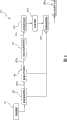
图3的范例中,影像撷取模组301例如可通过一场景中物体移动,来撷取多个不同时间点在摄影机移动平台或是静态平台的状态下所拍摄的连续影像301a。影像对齐模组303可根据不同时间点于移动平台的状态下所拍摄的连续影像的背景移动求得对齐参数,并可将不同时间点于移动平台的状态下所拍摄的连续影像的背景对齐。例如图5所示,可从三个连续时间点t-1、t、t+1,的三张相邻影像Ft-1、Ft、Ft+1中,求出两张影像的对齐参数,将影像Ft-1对齐至影像Ft,Ft+1对齐至影像Ft,如此可消除因为摄影机移动所造成的画面变换。In the example shown in FIG. 3 , the
本揭露的实施范例中,可以有多种实施背景移动校正补偿的范例,例如,利用多阶层移动模组估算技术(multi-resolution estimation of parametricmotion models),此技术先利用高斯低通滤波器建立多阶层影像金字塔,再于每阶层影像上由相邻画面差值平方最小化,估算出相邻画面间运动参数。In the implementation example of the present disclosure, there can be many examples of implementing background motion correction and compensation, for example, using multi-resolution estimation of parametric motion models (multi-resolution estimation of parametric motion models), this technology first uses a Gaussian low-pass filter to establish a multi-resolution Hierarchical image pyramid, and then minimize the square of the difference between adjacent frames on each layer of images to estimate the motion parameters between adjacent frames.
图6是进行连续画面差异的一个范例示意图,与本揭露的某些实施范例一致。参考图6,影像Ft+1、Ft-1对齐后,由与影像Ft的差异,可得到两个影像差异(frame difference)610与620,亦即影像Ft+1与Ft的差异以及影像Ft-1与Ft的差异。再利用影像差异610与620以及一交集(AND)运算630,求出差异影像305a,侦测出可能的前景位置。也就是说,连续画面差异模组305可将三连续影像分析应用在补偿校正后的影像,来侦测移动物体可能的前景位置。FIG. 6 is a schematic diagram of an example of sequential frame difference, which is consistent with some embodiments of the present disclosure. Referring to Fig. 6, after the images Ft+1 and Ft-1 are aligned, two frame differences (frame difference) 610 and 620 can be obtained from the difference with the image Ft , that is, the frame difference between the images Ft+1 and Ft difference and the difference between image Ft-1 and Ft . Then use
以下是从三张相邻影像Ft-1、Ft、Ft+1求出此差异影像的一个范例。假设Xi代表影像的画面位置,C(Xi)是影像画面位置的一种表示矩阵而能与运动参数矩阵进行相乘运算,则影像Ft-1校正至影像Ft,影像Ft+1校正至影像Ft后,可得到两个运动参数At-1及At+1,经由以下公式,可得到两个影像差异FDt-1及FDt+1:The following is an example of calculating the difference image from three adjacent images Ft-1 , Ft , Ft+1 . Assuming that Xi represents the frame position of the image, C(Xi ) is a representation matrix of the image frame position and can be multiplied with the motion parameter matrix, then the image Ft-1 is corrected to the image Ft , and the image Ft+ 1 After correcting to the image Ft , two motion parameters At-1 and At+1 can be obtained, and two image differences FDt-1 and FDt+1 can be obtained through the following formula:

其中k=t-1,t+1,δ1为临界值。使用“AND”逻辑表达式处理影像差异FDt-1及FDt+1,即可得到差异影像FAt,亦即FAt(Xi)=FDt-1(Xi)∧FDt+1(Xi)。Among them k=t-1, t+1, δ1 is the critical value. Use the "AND" logical expression to process the image differences FDt-1 and FDt+1 to obtain the difference image FAt , that is, FAt (Xi )=FDt-1 (Xi )∧FDt+1 (Xi ).
如果是静态平台的状态下所拍摄的连续影像301a,则不需要将相邻影像对齐,可直接将不同时间点撷取的影像,进行连续画面差异,求出此差异影像305a,以侦测移动物体可能的前景位置。If it is the
距离转换模组307可利用一距离转换技术,将差异影像305a转成距离地图307a。此距离转换技术,例如下列公式,可将差异影像FAt转成距离地图Dt:The
其中Xk为距离Xi最近的前景点,δ2为最大容许距离。换句话说,距离地图Dt的每一点的值是最近的前景点的距离除以最大容许距离的一个比例,距离前景点越近,其值越小,表示愈有可能属于移动物体;反之亦然。图7是进行距离转换的一个范例示意图,与本揭露的某些实施范例一致。图7中,差异影像的范例705进行距离转换后,产生的距离地图的范例如标号707所示。距离地图对移动物体所在的位置提供了一个机率分布,因此,从距离地图可以看出整个移动物体在画面内的发生区域,增强移动物体侦测的稳定性。Among them, Xk is the foreground point closest toXi , and δ2 is the maximum allowable distance. In other words, the value of each point of the distance map Dt is a ratio of the distance of the nearest foreground point divided by the maximum allowable distance, the closer the distance to the foreground point, the smaller the value, indicating that it is more likely to belong to a moving object; and vice versa Of course. FIG. 7 is a schematic diagram of an example of performing distance conversion, which is consistent with some implementation examples of the present disclosure. In FIG. 7 , after distance conversion is performed on the example 705 of the difference image, an example of the generated distance map is indicated by
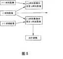
背景相减模组309将距离地图应用至背景相减技术,并与目前撷取影像比对而得到此移动物体的信息。图8是一范例示意图,进一步说明背景相减模组的运作。如图8所示,背景相减模组309将对齐参数811使用至背景模型812,以将背景对齐至目前撷取影像。将对齐后的背景模型821以及t时间影像Ft,以距离地图,如标号707的范例,作为更新率来更新背景模型,如标号830所示。并且此对齐后的背景经由距离地图,如标号707的范例的权重,与t时间撷取的影像比对,进行t时间的前景侦测,而侦测出此移动物体,如标号809的范例。The
在前景侦测阶段,由于背景对齐误差,可考虑一个区域的背景点来侦测前景。而连续画面差异的距离转换结果,即距离地图Dt,则作为前景判定的可适性的(adaptive)门槛值(threshold value),若前景机率较高,则门槛值愈低,反之亦然。当背景更新时,同样利用距离地图Dt作为可适性的更新率(updatingrate),若前景机率较高,则维持原来的背景值,反之亦然。In the foreground detection stage, due to the background alignment error, the background points of an area can be considered to detect the foreground. The distance conversion result of the difference between consecutive frames, ie, the distance map Dt , is used as an adaptive threshold value for foreground determination. If the foreground probability is higher, the threshold value is lower, and vice versa. When the background is updated, the distance map Dt is also used as the adaptive updating rate (updating rate). If the probability of the foreground is high, the original background value is maintained, and vice versa.
由于背景相减模组309将距离地图应用至背景相减技术,在时间t的前景侦测以及背景更新时,利用距离地图Dt作为参数调整的依据。因此得出的移动物体信息不仅可以看出移动物体的整体外型,移动物体内部区域的信息也比较完整。Since the
图9是整合前述图5至图8的一个范例示意图,与本揭露的某些实施范例一致。从图9范例以及前述的说明,可以清楚看出本揭露的实施范例先补偿因摄影机平台移动所造成的画面移动,再由结合背景相减与连续画面差异技术,将连续画面差异的结果利用距离转换产生出距离地图以辅助背景相减法,稳固地侦测出前景的移动物体区域。FIG. 9 is an example schematic diagram integrating the above-mentioned FIGS. 5 to 8 , which is consistent with some embodiments of the present disclosure. From the example in Figure 9 and the foregoing description, it can be clearly seen that the implementation example of this disclosure first compensates for the image movement caused by the movement of the camera platform, and then combines the background subtraction and continuous image difference technology to use the result of the continuous image difference using the distance The conversion produces a distance map to assist background subtraction to robustly detect foreground moving object regions.
本揭露的实施范例中,以连续画面差异技术来辅助背景相减技术,在背景移动校正补偿后的影像上侦测前景物体,来达成利用单摄影机即可有效且实时地进行移动摄影机的移动物体侦测。而本揭露的实施范例更应用距离转换技术,将连续画面差异的侦测结果转换为距离地图,如此,对物体所在的位置给了一个机率分布,将此分布应用至背景相减技术中,成为前景侦测及背景更新的很好的权重值。In the implementation example of this disclosure, the background subtraction technology is assisted by the continuous frame difference technology, and the foreground object is detected on the image after the background motion correction and compensation, so as to achieve the moving object that can move the camera effectively and in real time by using a single camera detection. However, the implementation example disclosed in this disclosure uses the distance conversion technology to convert the detection results of the difference between consecutive frames into a distance map. In this way, a probability distribution is given for the position of the object, and this distribution is applied to the background subtraction technology to become Good weight values for foreground detection and background updating.
前景侦测时对于移动物体部分加强权重,而背景更新时将降低移动物体部分的权重,使得移动物体更易被侦测出。如此,将可改善既有的背景相减技术的缺点,而更稳定地侦测出移动物体。本揭露的实施范例中,使用连续画面差异来帮助背景相减的机制,除了能够在移动平台实施外,也可以应用在固定式平台来增强移动物体侦测的稳定性。When the foreground is detected, the weight of the moving object will be strengthened, and the weight of the moving object will be reduced when the background is updated, making the moving object easier to detect. In this way, the shortcomings of the existing background subtraction technology can be improved, and moving objects can be detected more stably. In the implementation example of the present disclosure, the mechanism of using continuous frame difference to help background subtraction can be implemented not only on mobile platforms, but also on fixed platforms to enhance the stability of moving object detection.
以上所述者仅为本发明的实施范例而已,当不能依此限定本发明实施的范围。凡是依本发明权利要求范围所作的均等变化与修饰,皆应仍属本发明专利涵盖的范围内。What is described above is only an implementation example of the present invention, and should not limit the implementation scope of the present invention accordingly. All equivalent changes and modifications made according to the claims of the present invention shall still fall within the scope covered by the patent of the present invention.
Claims (15)
Priority Applications (1)
| Application Number | Priority Date | Filing Date | Title |
|---|---|---|---|
| CN2007103081246ACN101469987B (en) | 2007-12-29 | 2007-12-29 | Moving object detection device and method |
Applications Claiming Priority (1)
| Application Number | Priority Date | Filing Date | Title |
|---|---|---|---|
| CN2007103081246ACN101469987B (en) | 2007-12-29 | 2007-12-29 | Moving object detection device and method |
Publications (2)
| Publication Number | Publication Date |
|---|---|
| CN101469987A CN101469987A (en) | 2009-07-01 |
| CN101469987Btrue CN101469987B (en) | 2010-12-01 |
Family
ID=40827684
Family Applications (1)
| Application Number | Title | Priority Date | Filing Date |
|---|---|---|---|
| CN2007103081246AExpired - Fee RelatedCN101469987B (en) | 2007-12-29 | 2007-12-29 | Moving object detection device and method |
Country Status (1)
| Country | Link |
|---|---|
| CN (1) | CN101469987B (en) |
Families Citing this family (2)
| Publication number | Priority date | Publication date | Assignee | Title |
|---|---|---|---|---|
| CN103017779B (en)* | 2009-12-08 | 2015-08-19 | 财团法人工业技术研究院 | Method and system for processing road view image by mobile camera |
| TWI571830B (en)* | 2016-05-31 | 2017-02-21 | 和碩聯合科技股份有限公司 | Moving object detecting method |
Citations (4)
| Publication number | Priority date | Publication date | Assignee | Title |
|---|---|---|---|---|
| US6611268B1 (en)* | 2000-05-30 | 2003-08-26 | Microsoft Corporation | System and process for generating 3D video textures using video-based rendering techniques |
| US20070177800A1 (en)* | 2006-02-02 | 2007-08-02 | International Business Machines Corporation | Method and apparatus for maintaining a background image model in a background subtraction system using accumulated motion |
| CN101017573A (en)* | 2007-02-09 | 2007-08-15 | 南京大学 | Method for detecting and identifying moving target based on video monitoring |
| CN101038671A (en)* | 2007-04-25 | 2007-09-19 | 上海大学 | Tracking method of three-dimensional finger motion locus based on stereo vision |
- 2007
- 2007-12-29CNCN2007103081246Apatent/CN101469987B/ennot_activeExpired - Fee Related
Patent Citations (4)
| Publication number | Priority date | Publication date | Assignee | Title |
|---|---|---|---|---|
| US6611268B1 (en)* | 2000-05-30 | 2003-08-26 | Microsoft Corporation | System and process for generating 3D video textures using video-based rendering techniques |
| US20070177800A1 (en)* | 2006-02-02 | 2007-08-02 | International Business Machines Corporation | Method and apparatus for maintaining a background image model in a background subtraction system using accumulated motion |
| CN101017573A (en)* | 2007-02-09 | 2007-08-15 | 南京大学 | Method for detecting and identifying moving target based on video monitoring |
| CN101038671A (en)* | 2007-04-25 | 2007-09-19 | 上海大学 | Tracking method of three-dimensional finger motion locus based on stereo vision |
Non-Patent Citations (2)
| Title |
|---|
| 胡建华,杨帆,徐健健.基于分块差分与背景减除的运动检测.电子测量技术30 10.2007,30(10),49-53. |
| 胡建华,杨帆,徐健健.基于分块差分与背景减除的运动检测.电子测量技术30 10.2007,30(10),49-53.* |
Also Published As
| Publication number | Publication date |
|---|---|
| CN101469987A (en) | 2009-07-01 |
Similar Documents
| Publication | Publication Date | Title |
|---|---|---|
| TWI353778B (en) | Moving object detection apparatus and method | |
| JP5656567B2 (en) | Video processing apparatus and method | |
| US8165348B2 (en) | Detecting objects crossing a virtual boundary line | |
| CN102592146B (en) | Face detection and camera tripod control method applied to video monitoring | |
| CN101098465A (en) | A method for detecting and tracking moving objects in video surveillance | |
| KR20150084939A (en) | Image stabilization techniques for video surveillance systems | |
| CN108229475A (en) | Wireless vehicle tracking, system, computer equipment and readable storage medium storing program for executing | |
| CN101312524A (en) | Moving object detection device and method using optical track analysis | |
| US20110074927A1 (en) | Method for determining ego-motion of moving platform and detection system | |
| CN116433728A (en) | DeepSORT target tracking method for shake blur scene | |
| CN115116127A (en) | A fall detection method based on computer vision and artificial intelligence | |
| CN118570312B (en) | A multi-camera collaborative calibration method and application for dynamic vision sensors | |
| WO2020078140A1 (en) | Optimization system and method for motion model | |
| CN106611165B (en) | A car window detection method and device based on correlation filtering and color matching | |
| CN101469987B (en) | Moving object detection device and method | |
| WO2020095644A1 (en) | State-change detection device, state-change detection method, and computer-readable recording medium | |
| CN111369578B (en) | Intelligent tracking method and system for cradle head transaction | |
| CN119269028A (en) | Screen jitter non-intrusive detection method, system and medium | |
| CN106682582A (en) | Compressed sensing appearance model-based face tracking method and system | |
| CN115601679B (en) | Video anomaly detection method and system based on multidimensional second-order memory guided network | |
| CN112396639A (en) | Image alignment method | |
| KR102450466B1 (en) | System and method for removing camera motion in video | |
| JP2011096072A (en) | Device and program for detecting object | |
| Ryu et al. | Video stabilization for robot eye using IMU-aided feature tracker | |
| CN113516684B (en) | Image processing method, device, equipment and storage medium |
Legal Events
| Date | Code | Title | Description |
|---|---|---|---|
| C06 | Publication | ||
| PB01 | Publication | ||
| C10 | Entry into substantive examination | ||
| SE01 | Entry into force of request for substantive examination | ||
| C14 | Grant of patent or utility model | ||
| GR01 | Patent grant | ||
| CF01 | Termination of patent right due to non-payment of annual fee | ||
| CF01 | Termination of patent right due to non-payment of annual fee | Granted publication date:20101201 |