CN101469736B - hinge structure - Google Patents
hinge structureDownload PDFInfo
- Publication number
- CN101469736B CN101469736BCN200710203485.4ACN200710203485ACN101469736BCN 101469736 BCN101469736 BCN 101469736BCN 200710203485 ACN200710203485 ACN 200710203485ACN 101469736 BCN101469736 BCN 101469736B
- Authority
- CN
- China
- Prior art keywords
- rotating shaft
- guide rail
- slider
- hinge structure
- cam
- Prior art date
- Legal status (The legal status is an assumption and is not a legal conclusion. Google has not performed a legal analysis and makes no representation as to the accuracy of the status listed.)
- Expired - Fee Related
Links
Images


Classifications
- E—FIXED CONSTRUCTIONS
- E05—LOCKS; KEYS; WINDOW OR DOOR FITTINGS; SAFES
- E05D—HINGES OR SUSPENSION DEVICES FOR DOORS, WINDOWS OR WINGS
- E05D15/00—Suspension arrangements for wings
- E05D15/40—Suspension arrangements for wings supported on arms movable in vertical planes
- E05D15/406—Suspension arrangements for wings supported on arms movable in vertical planes with pivoted arms and sliding guides
- E—FIXED CONSTRUCTIONS
- E05—LOCKS; KEYS; WINDOW OR DOOR FITTINGS; SAFES
- E05D—HINGES OR SUSPENSION DEVICES FOR DOORS, WINDOWS OR WINGS
- E05D3/00—Hinges with pins
- E05D3/06—Hinges with pins with two or more pins
- E05D3/12—Hinges with pins with two or more pins with two parallel pins and one arm
- E—FIXED CONSTRUCTIONS
- E05—LOCKS; KEYS; WINDOW OR DOOR FITTINGS; SAFES
- E05Y—INDEXING SCHEME ASSOCIATED WITH SUBCLASSES E05D AND E05F, RELATING TO CONSTRUCTION ELEMENTS, ELECTRIC CONTROL, POWER SUPPLY, POWER SIGNAL OR TRANSMISSION, USER INTERFACES, MOUNTING OR COUPLING, DETAILS, ACCESSORIES, AUXILIARY OPERATIONS NOT OTHERWISE PROVIDED FOR, APPLICATION THEREOF
- E05Y2999/00—Subject-matter not otherwise provided for in this subclass
Landscapes
- Engineering & Computer Science (AREA)
- Mechanical Engineering (AREA)
- Telephone Set Structure (AREA)
Abstract
Description
Translated fromChinese技术领域technical field
本发明是关于一种铰链结构,尤其是关于一种双轴铰链结构。The present invention relates to a hinge structure, in particular to a biaxial hinge structure.
背景技术Background technique
目前,手机、掌上电脑等便携式电子装置一般包括一个本体和一个盖体,显示屏设于盖体上,为使显示屏具有较佳视角,通常需要通过铰链结构将盖体可旋转地连接至本体上。At present, portable electronic devices such as mobile phones and palmtop computers generally include a body and a cover. superior.
一种现有的手机铰链结构,包括制动凸轮、滑动凸轮、储能弹簧和卡环,该制动凸轮的的中部延伸有一个枢轴,且该枢轴的末端开设有一个卡槽,该滑动凸轮中部开设有一个通孔。该枢轴穿过滑动凸轮上的通孔和储能弹簧,卡环卡入枢轴末端的卡槽内。An existing mobile phone hinge structure includes a braking cam, a sliding cam, an energy storage spring and a snap ring. A pivot extends from the middle of the braking cam, and a slot is opened at the end of the pivot. A through hole is provided in the middle part of the sliding cam. The pivot passes through the through hole on the sliding cam and the energy storage spring, and the snap ring snaps into the draw-in groove at the end of the pivot.
然而,采用该种铰链结构的手机的盖体仅能相对本体前后翻转,而手机的摄像单元通常被安装在该盖体上以拍摄外景,所以当使用者需采用该种手机自拍时,其只能在看不到显示屏及按键的情况下进行拍摄,操作较为不便。另外,采用该种铰链结构的手机的盖体仅能相对本体翻转,运动方式单一。However, the cover body of the mobile phone adopting this kind of hinge structure can only be flipped back and forth relative to the main body, and the camera unit of the mobile phone is usually installed on the cover body to shoot outside scenes, so when the user needs to use this kind of mobile phone to take a selfie, it only needs to Shooting can be done without seeing the display screen and buttons, which is inconvenient to operate. In addition, the cover body of the mobile phone adopting this hinge structure can only be flipped relative to the main body, and the movement mode is single.
发明内容Contents of the invention
鉴于以上内容,有必要提供一种可使电子装置的盖体相对本体做双轴向旋转以及滑动的铰链结构。In view of the above, it is necessary to provide a hinge structure capable of biaxially rotating and sliding the cover of the electronic device relative to the main body.
一种铰链结构,包括一个第一转动组件、一个第二转动组件、一个滑动件、一个导轨、一个第一支架及一个第二支架,该第一转动组件包括一个第一转轴,该第二转动组件包括一个第二转轴,该第一支架及导轨均与第一转轴连接,且该第一支架及导轨中至少一个与第一转轴为可转动连接,该第二支架及该滑动件均与第二转轴连接,且该第二支架及滑动件中至少一个与第二转轴为可转动连接,该第一转轴与第二转轴基本平行,该滑动件设于导轨上且可沿着导轨滑动。A hinge structure, comprising a first rotating assembly, a second rotating assembly, a slider, a guide rail, a first bracket and a second bracket, the first rotating assembly includes a first rotating shaft, the second rotating The assembly includes a second rotating shaft, the first bracket and the guide rail are both connected to the first rotating shaft, and at least one of the first bracket and the guide rail is rotatably connected to the first rotating shaft, the second bracket and the sliding member are connected to the first rotating shaft The two rotating shafts are connected, and at least one of the second bracket and the sliding member is rotatably connected to the second rotating shaft, the first rotating shaft is substantially parallel to the second rotating shaft, and the sliding member is arranged on the guide rail and can slide along the guide rail.
相较现有技术,所述铰链结构的第一支架及导轨中至少一个与第一转轴为可转动连接,该第二支架及滑动件中至少一个与第二转轴为可转动连接,且第一转轴与第二转轴基本平行,该第一支架可绕第一转轴的中心轴线旋转,第二支架可绕第二转轴的中心轴线旋转,所以将第一支架及第二支架分别与电子装置的本体和盖体连接后,该电子装置的盖体不仅可以相对本体作开合运动,还可做旋转运动,因此,该电子装置的使用者在使用安装在该铰链结构的导轨上的摄像单元对自己拍照时,可将盖体相对本体打开后,再将显示屏旋转180度,即可让使用者在进行拍照操作的同时观看显示屏上的内容以对自己的位置进行调整,从而获得较佳的拍摄效果。另外,采用该种铰链结构的电子装置在被打开后,可将其盖体旋转180度后再合拢,此时,该电子装置的显示屏朝向使用者且可作为滑盖型电子装置使用,只需使盖体相对本体滑行一段距离,即使滑动件在导轨上滑行一段距离,就可露出本体上的键盘以进行相关操作。Compared with the prior art, at least one of the first bracket and the guide rail of the hinge structure is rotatably connected to the first rotating shaft, at least one of the second bracket and the sliding member is rotatably connected to the second rotating shaft, and the first The rotating shaft is substantially parallel to the second rotating shaft, the first support can rotate around the central axis of the first rotating shaft, and the second support can rotate around the central axis of the second rotating shaft, so the first support and the second support are respectively connected to the body of the electronic device After being connected with the cover body, the cover body of the electronic device can not only perform opening and closing movement relative to the main body, but also perform rotational movement. When taking pictures, the cover can be opened relative to the main body, and then the display screen can be rotated 180 degrees, so that the user can watch the content on the display screen to adjust his position while taking pictures, so as to obtain a better view Shooting effect. In addition, after the electronic device adopting this kind of hinge structure is opened, its cover body can be rotated 180 degrees and then closed again. At this time, the display screen of the electronic device faces the user and can be used as a sliding cover electronic device. The cover needs to slide a certain distance relative to the main body, even if the sliding part slides a certain distance on the guide rail, the keyboard on the main body can be exposed for related operations.
附图说明Description of drawings
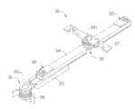
图1是本发明较佳实施方式一的铰链结构的立体图;Fig. 1 is a perspective view of a hinge structure in a preferred embodiment 1 of the present invention;
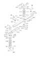
图2是本发明较佳实施方式一的铰链结构的立体分解图;Fig. 2 is a three-dimensional exploded view of the hinge structure of the preferred embodiment 1 of the present invention;
图3是本发明较佳实施方式一的铰链结构的另一视角立体分解图;Fig. 3 is another perspective exploded view of the hinge structure of the preferred embodiment 1 of the present invention;
图4是本发明较佳实施方式一的铰链结构的导轨相对第一支架转过一定角度及第二支架相对滑动件转过一定角度后的立体图;Fig. 4 is a perspective view of the guide rail of the hinge structure according to the preferred embodiment 1 of the present invention after a certain angle is rotated relative to the first bracket and the second bracket is rotated through a certain angle relative to the slider;
图5是图4所示的铰链结构的滑动件沿着导轨滑行一段距离后的立体图;Fig. 5 is a perspective view of the sliding part of the hinge structure shown in Fig. 4 after sliding along the guide rail for a certain distance;
图6是本发明较佳实施方式二的电子装置处于一般闭合状态的立体图;6 is a perspective view of an electronic device in a generally closed state according to a second preferred embodiment of the present invention;
图7是图6所示电子装置的本体相对盖体打开一定角度的立体图;7 is a perspective view of the body of the electronic device shown in FIG. 6 opened at a certain angle relative to the cover;
图8是图6所示的电子装置的盖体相对本体进行双轴旋转的立体图;FIG. 8 is a perspective view of a biaxial rotation of the cover of the electronic device shown in FIG. 6 relative to the main body;
图9是图6所示的电子装置的处于显示屏朝外的闭合状态的立体图;9 is a perspective view of the electronic device shown in FIG. 6 in a closed state with the display screen facing outward;
图10是图9所示的电子装置的盖体相对本体滑行一段距离的立体图。FIG. 10 is a perspective view of the cover of the electronic device shown in FIG. 9 sliding relative to the main body for a certain distance.
具体实施方式Detailed ways
下面将结合附图及实施例对本发明的铰链结构做进一步详细说明。The hinge structure of the present invention will be further described in detail with reference to the accompanying drawings and embodiments.
请参阅图1,本较佳实施方式一提供一种铰链结构30,其包括第一转动组件31、第二转动组件32、导轨33、滑动件34、两个限位组件35、第一支架36及第二支架37。Please refer to FIG. 1 , this preferred embodiment provides a
请同时参阅图2及图3,该第一转动组件31包括一个第一转轴311、一个第一凸轮313及多个弹片315。该第一转轴311为一空心轴,其一端部形成有凸缘3111,相对的另一端部延伸形成有两个相对的凸起3112,且该第一转轴311的截面形状为类椭圆形。该第一凸轮313大致呈圆环状,其一端面上等间距开设有四个凹槽3131以形成一个凸轮面3132,其中央开设有一个与第一转轴311相配合的类椭圆形通孔3133。该第一凸轮313的侧面上还开设有一个限位槽3134。该弹片315中央开设有一个供第一转轴311穿设的圆形通孔3151。该第一凸轮313、弹片315均可套设于第一转轴311上,且由于该第一凸轮313上的通孔3133为与第一转轴311相适配的类椭圆形,所以第一凸轮313与第一转轴311之间为不可转动连接。Please refer to FIG. 2 and FIG. 3 at the same time, the first rotating
该第二转动组件32包括一个第二转轴321、一个第二凸轮323、多个弹片325及一个垫片327。该第二转轴321为一空心轴,其一端部形成有凸缘3211,相对的另一端部延伸形成有两个相对的凸起3212,该凸缘3211的侧面上开设有一个限位槽3213。该第二转轴321的截面形状为类椭圆形。该第二凸轮323大致呈圆环状,其一端面上设置有两个相对的凸起3231以形成一个凸轮面3232,该第二凸轮323的中央还开设有一个与第二转轴321相配合的类椭圆形通孔3233。该弹片325中央均开设有一个供第二转轴321穿设的圆形通孔3251。该垫片327中央开设有一个与第二转轴321相配合的类椭圆形通孔3271。该第二凸轮323、弹片325及垫片327均可套设于第二转轴321上,且由于第二凸轮323及垫片327上的通孔3233、3271为与第一转轴311相适配的类椭圆形,所以垫片327、第二凸轮323与第二转轴321之间为不可转动连接。The
该导轨33包括一个本体331及由该本体331一端延伸形成的定位片333。该本体331上开设有一个滑槽3311,该滑槽3311底部中央开设有一个盲孔3313。该定位片333中央开设有一个供第一转轴311穿设的通孔3331,其朝向第一凸轮313的端面上形成有两个相对的凸块335,以与第一凸轮313的凸轮面3132相配合。该定位片333的上述端面还在靠近本体331处形成有一个用于在第一凸轮313的限位槽3134中滑动的限位凸起336。The
该滑动件34包括两个长条状的滑条341及连接该两个滑条341且厚度小于滑条341的连接片342。该滑条341的端部分别开设有一个容纳孔3411及一个盲孔3412,且该容纳孔3411部分为锥孔。该滑条341朝向导轨33的端面边缘还延伸形成有凸条3413,该凸条3413与本体331的滑槽3311配合,以使该滑动件34沿着滑槽3311相对导轨33滑动。该连接片342中央开设有一个供第二转轴321穿设的通孔3421,且其朝向第二凸轮323的端面上形成有两个相对的凹槽3422,以与第二凸轮323的凸轮面3232相配合。该连接片342远离第二凸轮323的端面上还形成有一个限位凸块345,该限位凸块345在凸缘3211上的限位槽3213中滑动。The sliding
该两个限位组件35分别设置于滑动件34的两端。该限位组件35包括一个铆钉351、一个固定片352、一个压簧353及一个限位滚珠354。该固定片352的一端开设有一个贯穿孔356以供铆钉351穿设。该固定片352与滑动件34相对的端面上还延伸有一个与滑动件34的容纳孔3411配合的凸柱3521。该限位滚珠354及压簧353容纳于滑条341的容纳孔3411中。该铆钉351用于铆入滑动件34上的盲孔3412以将固定片352固定于滑动件34上。The two
该第一支架36包括一个卡合片361及与该卡合片361垂直相连的锁合片362。该卡合片361上开设有一个与第一转轴311端部相配合的非圆变形孔363,以使第一支架36与第一转轴311为不可转动连接。该锁合片362用于与电子装置的本体相连接。The
该第二支架37包括一个卡合片371及由该卡合片371一侧垂直该卡合片371延伸形成的两个锁合片372。该卡合片371中部开设有一个与第二转轴321端部相配合的非圆变形孔373,以使第二支架37与第二转轴321为不可转动连接。该锁合片372用于与电子装置的盖体相连接。The
装配该铰链结构30时,先将滑动件34置入该导轨33的滑槽3311中,以使该滑动件34沿着导轨33滑动,且使容纳孔3411为锥孔的部分靠近导轨33。接着使第一转轴311依次穿过导轨33的通孔3331、第一凸轮313及弹片315,并将第一支架36固定连接于第一转轴311的端部,然后将两个凸起3112分别向外弯折90度,以使第一支架36不能脱出。将第二转轴321依次穿过滑动件34的通孔3421、第二凸轮323、弹片325及垫片327,并将第二支架37固定连接于第一转轴311的端部,并将两个凸起3212分别向外弯折90度,以使第二支架37不能脱出。接着将两个限位组件35分别装设于该滑动件34的两端,此时,该限位组件35中的压簧353被压缩于滑动件34的容纳孔3411中,并且由于该容纳孔3411部分为锥孔,该限位滚珠354受到压簧353的弹力作用且仅部分从容纳孔3411伸出。When assembling the
请参阅图1至图3,装配完毕后,该第一支架36可相对导轨33绕第一转轴311的中心轴线旋转,且导轨33上的限位凸起336在第一凸轮313的限位槽3134中运动,用于限制该第一支架36相对导轨33的转动范围。第一凸轮313的凸轮面3132与定位片333上的凸块335相配合,可使第一转轴311每旋转90度后定位一次。该第二支架37可相对滑动件34绕第二转轴321的中心轴线旋转,且滑动件34上的限位凸块345在凸缘3211的限位槽3213中滑动,用于限制该第二支架36相对滑动件34的转动范围。第二凸轮323的凸轮面3232与连接片342上的两个凹槽3422相配合,可使第二转轴321在转过180度后定位。Please refer to FIG. 1 to FIG. 3 , after assembly, the
请参阅图4及图5,滑动件34相对导轨33滑动至一预定位置时,即当滑动件34滑动至其上的容纳孔3411与导轨上的盲孔3313对准时,该限位滚珠354在压簧353的弹力下卡入滑动件上的盲孔3313,从而使滑动件34在导轨33上定位。导轨33相对第一转轴311的中心轴线旋转时,该滑动件34、第二转动组件32及第二支架37与导轨33一起相对第一转轴311及第一支架36转动,在此过程中,该导轨33上的限位凸起336将在第一凸轮313的限位槽3134中运动,当导轨33上的限位凸起336与第一凸轮313的限位槽3134的端部相抵时,该导轨33停止转动。第二支架37相对滑动件34转动时,该第二转轴321、第二凸轮323及第二支架37一起相对导轨33、滑动件34、第一转轴311及第一支架36转动,在此过程中,第二凸轮323及垫片327将随其一起旋转,当滑动件34上的限位凸块345与凸缘3211上的限位槽3213的端部相抵时,该第二转轴321停止转动。4 and 5, when the
请参阅图6,本较佳实施方式二提供一种采用上述铰链结构30的手机50,该手机50包括带显示屏511的盖体51、带有多个按键521的本体52及铰链结构30。该铰链结构30的第一支架36与本体52相连,第二支架37与盖体51相连。请参阅图7及图9,使导轨33围绕第一转轴311的中心轴线旋转,可使盖体51相对本体52做开合运动;请参阅图8,使第二支架37相对第二转轴321的中心轴线旋转,可使盖体51作旋转运动。请参阅图10,使滑动件34沿着导轨33滑动,可使盖体51相对本体52滑动,且当限位滚珠354卡入导轨33上的盲孔3313中时,盖体51停止运动。该手机50还包括一个摄像单元(图未示),其设置于导轨33上。Please refer to FIG. 6 , the second preferred embodiment provides a
当手机50的使用者需对自己拍照时,只需将盖体51相对本体52绕第一转轴311打开一定角度后,然后将盖体51绕第二转轴321旋转180度,即可让使用者在使用摄像单元对自己拍照的同时观看显示屏上显示的内容,从而对自己的位置进行调整,以取得较佳的拍摄效果。另外,该手机50可作为翻盖型及滑盖型两种手机使用,如图6及图7所示,该手机50可通过导轨33绕第一转轴311的中心轴线旋转,以实现翻盖型手机的功能,如图9及图10所示,该手机可通过滑动件34沿着导轨33滑动,以实现滑盖手机的功能。而将手机50从图6所示的状态转换为图9所示的状态只需进行以下操作:将手机50的盖体51相对本体52打开后,再将盖体51绕第二转轴321旋转180度,然后将其合拢即可。When the user of the
可以理解,该铰链结构30也可应用于其他便携式电子装置,如掌上电脑等,而且,第一转轴311及第二转轴321的截面也可为其它形状,如正多边形,但与其相配合的凸轮上也需相应开设形状相适配的通孔,另外,该铰链结构30的第一支架36与第一转轴311也可为可转动连接,而第一转轴311与导轨33为固定连接,其同样可使采用该铰链结构30的电子装置的盖体相对本体做双轴向旋转,当然,该第一支架36及导轨33也可均与第一转轴311可转动连接。同理该第二支架37与第二转轴321也可为可转动连接,而第二转轴321与滑动件34为固定连接,或者第二支架37及滑动件34均与第二转轴321可转动连接。此外,该固定片352也可通过焊接的方式固定至滑动件34的端部,且该固定片352上也可不设置凸柱3521。It can be understood that the
Claims (10)
Priority Applications (2)
| Application Number | Priority Date | Filing Date | Title |
|---|---|---|---|
| CN200710203485.4ACN101469736B (en) | 2007-12-27 | 2007-12-27 | hinge structure |
| US12/124,167US7836554B2 (en) | 2007-12-27 | 2008-05-21 | Double hinge assembly and electronic device using the same |
Applications Claiming Priority (1)
| Application Number | Priority Date | Filing Date | Title |
|---|---|---|---|
| CN200710203485.4ACN101469736B (en) | 2007-12-27 | 2007-12-27 | hinge structure |
Publications (2)
| Publication Number | Publication Date |
|---|---|
| CN101469736A CN101469736A (en) | 2009-07-01 |
| CN101469736Btrue CN101469736B (en) | 2012-03-28 |
Family
ID=40796371
Family Applications (1)
| Application Number | Title | Priority Date | Filing Date |
|---|---|---|---|
| CN200710203485.4AExpired - Fee RelatedCN101469736B (en) | 2007-12-27 | 2007-12-27 | hinge structure |
Country Status (2)
| Country | Link |
|---|---|
| US (1) | US7836554B2 (en) |
| CN (1) | CN101469736B (en) |
Families Citing this family (16)
| Publication number | Priority date | Publication date | Assignee | Title |
|---|---|---|---|---|
| CN101621552B (en)* | 2008-07-04 | 2013-10-09 | 深圳富泰宏精密工业有限公司 | Portable electronic device |
| US20100124944A1 (en)* | 2008-11-16 | 2010-05-20 | Inno Design, Inc. | Mobile communications device with slidable and pivotable screen |
| CN101754608B (en)* | 2008-12-05 | 2012-03-07 | 鸿富锦精密工业(深圳)有限公司 | Electronic device |
| US8199487B2 (en)* | 2009-03-10 | 2012-06-12 | Nokia Corporation | Extendible apparatus |
| US8023256B2 (en)* | 2009-03-10 | 2011-09-20 | Research In Motion Limited | Portable folding electronic device |
| US8649166B2 (en) | 2011-01-11 | 2014-02-11 | Z124 | Multi-positionable portable computer |
| US8648821B2 (en) | 2011-01-18 | 2014-02-11 | Flextronics Id, Llc | Spheroidal pivot for an electronic device |
| US8526178B2 (en)* | 2011-05-17 | 2013-09-03 | Flextronics Ap, Llc | All-in-one computing device with an adjustable screen height |
| US8681113B1 (en) | 2011-09-27 | 2014-03-25 | Flextronics Ap, Llc | Concept and operation mode for multi media AIO |
| US9101086B2 (en) | 2013-01-15 | 2015-08-04 | Blackberry Limited | Access panels for electronic devices |
| CN104279219B (en)* | 2013-07-02 | 2016-11-02 | 兆利科技工业股份有限公司 | Plug-in device capable of being unlocked in linkage manner |
| CN105202021B (en)* | 2014-06-30 | 2017-12-29 | 联想(北京)有限公司 | A kind of carriage and notebook computer |
| CN105306633B (en)* | 2015-10-23 | 2017-12-05 | 温州神一轴业有限公司 | A kind of mobile phone guide rail Minisize axial |
| US10501973B2 (en)* | 2016-06-14 | 2019-12-10 | Microsoft Technology Licensing, Llc | Hinge with free-stop function |
| US10301858B2 (en)* | 2016-06-14 | 2019-05-28 | Microsoft Technology Licensing, Llc | Hinge mechanism |
| US11599159B2 (en) | 2021-05-25 | 2023-03-07 | Microsoft Technology Licensing, Llc | Sliding double-pivot hinge |
Citations (3)
| Publication number | Priority date | Publication date | Assignee | Title |
|---|---|---|---|---|
| US6963485B2 (en)* | 2002-10-02 | 2005-11-08 | Samsung Electronics Co., Ltd. | Portable computer |
| US6972947B2 (en)* | 2003-08-13 | 2005-12-06 | Duncan Robert R | Laptop computer with elevating display |
| US20070289100A1 (en)* | 2006-06-14 | 2007-12-20 | Newell Operating Company | Casement Window Hinge |
Family Cites Families (19)
| Publication number | Priority date | Publication date | Assignee | Title |
|---|---|---|---|---|
| US1535668A (en)* | 1924-04-04 | 1925-04-28 | Harry L Hussmann Refrigerator | Hinge |
| US2208887A (en)* | 1938-10-12 | 1940-07-23 | Westwood Albert George | Hinge for windows, fanlights, and the like, opening outwardly |
| GB2132671B (en)* | 1982-10-30 | 1985-12-11 | James Scott Blair | Window |
| FR2574108B1 (en)* | 1984-12-05 | 1989-10-06 | Jaeger | DUAL JOINT CONNECTION HINGE |
| US5168426A (en)* | 1991-08-16 | 1992-12-01 | Beaver Computer Corporation | Hinge mechanism for cover panel of portable computer including slide mechanism |
| WO1994023476A1 (en)* | 1993-03-26 | 1994-10-13 | Zaidan Khalil S | Hinge assembly for electronic devices |
| DE4318607C2 (en)* | 1993-06-04 | 1995-07-13 | Grass Ag | Wide-angle hinge with an opening angle of approx. 180 ° |
| US5645333A (en)* | 1994-04-15 | 1997-07-08 | Sugatsune Industrial Co., Ltd. | Overhead door |
| DE9406636U1 (en)* | 1994-04-21 | 1994-06-16 | Roto Frank Ag, 70771 Leinfelden-Echterdingen | Connecting device for installing the wing of a roof window in the feed box |
| WO2003021408A2 (en)* | 2001-08-29 | 2003-03-13 | Danger, Inc. | Sliding display apparatus |
| JP4357900B2 (en)* | 2003-08-18 | 2009-11-04 | 加藤電機株式会社 | Slide hinge for small information terminal |
| US7356954B2 (en)* | 2003-12-01 | 2008-04-15 | Fujitsu Ten Limited | In-vehicle display apparatus |
| KR100631670B1 (en)* | 2003-12-09 | 2006-10-09 | 엘지전자 주식회사 | Portable terminal |
| GB2409236B (en)* | 2003-12-19 | 2008-05-28 | Lg Electronics Inc | Home-bar door opening/closing device for refrigerator |
| US7096539B2 (en)* | 2004-04-12 | 2006-08-29 | Advantage Manufacturing Corporation | Shim assembly for releasably engaging a hinge assembly |
| US20060148543A1 (en)* | 2004-12-30 | 2006-07-06 | Sony Ericsson Mobile Communications Ab | Flipper phone configuration |
| US7539526B2 (en)* | 2005-08-17 | 2009-05-26 | Nokia Corporation | Foldable keyboard for an electronic device |
| GB2430010B (en)* | 2005-09-07 | 2009-09-30 | Securistyle Ltd | Two bar stays |
| TWI296883B (en)* | 2006-03-17 | 2008-05-11 | Htc Corp | Portable electronic device |
- 2007
- 2007-12-27CNCN200710203485.4Apatent/CN101469736B/ennot_activeExpired - Fee Related
- 2008
- 2008-05-21USUS12/124,167patent/US7836554B2/ennot_activeExpired - Fee Related
Patent Citations (3)
| Publication number | Priority date | Publication date | Assignee | Title |
|---|---|---|---|---|
| US6963485B2 (en)* | 2002-10-02 | 2005-11-08 | Samsung Electronics Co., Ltd. | Portable computer |
| US6972947B2 (en)* | 2003-08-13 | 2005-12-06 | Duncan Robert R | Laptop computer with elevating display |
| US20070289100A1 (en)* | 2006-06-14 | 2007-12-20 | Newell Operating Company | Casement Window Hinge |
Also Published As
| Publication number | Publication date |
|---|---|
| CN101469736A (en) | 2009-07-01 |
| US20090165251A1 (en) | 2009-07-02 |
| US7836554B2 (en) | 2010-11-23 |
Similar Documents
| Publication | Publication Date | Title |
|---|---|---|
| CN101469736B (en) | hinge structure | |
| US9939851B2 (en) | Electronic device and hinge thereof | |
| US7499264B2 (en) | Compact devices with turn and slide concept | |
| US7478458B2 (en) | Biaxial hinge device of electrical equipment | |
| US7650671B2 (en) | Slide hinge module and slide type equipment utilizing the same | |
| CN101451573A (en) | Hinge mechanism | |
| JP5073563B2 (en) | Case mutual connection unit and portable terminal | |
| US9366064B1 (en) | Hinge structure | |
| US8259443B2 (en) | Tilting portable electronic device | |
| US20110287815A1 (en) | Rotating mechanism and electronic device using same | |
| TWI400397B (en) | Portable electronic device and opening-closing device thereof | |
| US10394286B2 (en) | Portable electronic device | |
| TW202037140A (en) | Electronic device with retractable lens moudle | |
| US8781540B2 (en) | Portable electronic device | |
| US20090145337A1 (en) | Slidable hinge | |
| US8248787B2 (en) | Portable electronic device with slidable cover | |
| US8164890B2 (en) | Sliding and tilting mechanism and portable electronic device using the same | |
| JP4474568B2 (en) | Electronic device and rotatable display lock device | |
| US8797730B2 (en) | Sliding module for electronic device | |
| US8325912B2 (en) | Handheld device having linkage supporter | |
| CN100544563C (en) | hinge structure | |
| JP2011146025A (en) | Portable electronic device | |
| US20120293926A1 (en) | Sliding module for electronic device | |
| CN201866477U (en) | An improved mobile electronic device support frame | |
| TWI338557B (en) | Hinge assembly |
Legal Events
| Date | Code | Title | Description |
|---|---|---|---|
| C06 | Publication | ||
| PB01 | Publication | ||
| C10 | Entry into substantive examination | ||
| SE01 | Entry into force of request for substantive examination | ||
| C14 | Grant of patent or utility model | ||
| GR01 | Patent grant | ||
| C17 | Cessation of patent right | ||
| CF01 | Termination of patent right due to non-payment of annual fee | Granted publication date:20120328 Termination date:20131227 |