CN101467328B - Charge equalization equipment - Google Patents
Charge equalization equipmentDownload PDFInfo
- Publication number
- CN101467328B CN101467328BCN2007800222221ACN200780022222ACN101467328BCN 101467328 BCN101467328 BCN 101467328BCN 2007800222221 ACN2007800222221 ACN 2007800222221ACN 200780022222 ACN200780022222 ACN 200780022222ACN 101467328 BCN101467328 BCN 101467328B
- Authority
- CN
- China
- Prior art keywords
- battery
- charge
- batteries
- switch
- transformers
- Prior art date
- Legal status (The legal status is an assumption and is not a legal conclusion. Google has not performed a legal analysis and makes no representation as to the accuracy of the status listed.)
- Active
Links
Images


Classifications
- H—ELECTRICITY
- H02—GENERATION; CONVERSION OR DISTRIBUTION OF ELECTRIC POWER
- H02J—CIRCUIT ARRANGEMENTS OR SYSTEMS FOR SUPPLYING OR DISTRIBUTING ELECTRIC POWER; SYSTEMS FOR STORING ELECTRIC ENERGY
- H02J7/00—Circuit arrangements for charging or depolarising batteries or for supplying loads from batteries
- H02J7/0013—Circuit arrangements for charging or depolarising batteries or for supplying loads from batteries acting upon several batteries simultaneously or sequentially
- H02J7/0014—Circuits for equalisation of charge between batteries
- H02J7/0016—Circuits for equalisation of charge between batteries using shunting, discharge or bypass circuits
- H—ELECTRICITY
- H02—GENERATION; CONVERSION OR DISTRIBUTION OF ELECTRIC POWER
- H02J—CIRCUIT ARRANGEMENTS OR SYSTEMS FOR SUPPLYING OR DISTRIBUTING ELECTRIC POWER; SYSTEMS FOR STORING ELECTRIC ENERGY
- H02J7/00—Circuit arrangements for charging or depolarising batteries or for supplying loads from batteries
- H02J7/0013—Circuit arrangements for charging or depolarising batteries or for supplying loads from batteries acting upon several batteries simultaneously or sequentially
- H02J7/0014—Circuits for equalisation of charge between batteries
- H02J7/0019—Circuits for equalisation of charge between batteries using switched or multiplexed charge circuits
- Y—GENERAL TAGGING OF NEW TECHNOLOGICAL DEVELOPMENTS; GENERAL TAGGING OF CROSS-SECTIONAL TECHNOLOGIES SPANNING OVER SEVERAL SECTIONS OF THE IPC; TECHNICAL SUBJECTS COVERED BY FORMER USPC CROSS-REFERENCE ART COLLECTIONS [XRACs] AND DIGESTS
- Y02—TECHNOLOGIES OR APPLICATIONS FOR MITIGATION OR ADAPTATION AGAINST CLIMATE CHANGE
- Y02T—CLIMATE CHANGE MITIGATION TECHNOLOGIES RELATED TO TRANSPORTATION
- Y02T10/00—Road transport of goods or passengers
- Y02T10/60—Other road transportation technologies with climate change mitigation effect
- Y02T10/70—Energy storage systems for electromobility, e.g. batteries
Landscapes
- Engineering & Computer Science (AREA)
- Power Engineering (AREA)
- Charge And Discharge Circuits For Batteries Or The Like (AREA)
- Secondary Cells (AREA)
Abstract
Translated fromChinese
Description
Translated fromChinese技术领域technical field
本发明总体上涉及一种电池电压均衡设备,更特别地,涉及一种电荷均衡设备,其使得变压器的初级和次级线圈能够被容易地制造,能够根据串联电池的充电状态来控制充入电池的电荷流,并且能够防止过电流流入当前正在充电的电池。The present invention relates generally to a battery voltage equalization device, and more particularly, to a charge equalization device which enables the primary and secondary coils of a transformer to be easily manufactured, and which can control the charging of the batteries according to the state of charge of the batteries connected in series charge flow, and can prevent excessive current from flowing into the battery currently being charged.
背景技术Background technique
许多系统使用每个由电池包或电池阵列形成的电池,包括相互串联地连接的多个电池单元。Many systems use batteries each formed from a battery pack or battery array, including multiple battery cells connected in series with one another.
当此类电池单元被充电以至于其电压显著高于额定充电范围内的电压或被放电至低于额定充电范围内的电压时,它们可能是危险的。Such cells can be hazardous when charged to a voltage significantly higher than within the rated charging range or discharged below a voltage within the rated charging range.
电池单元的充电状态之间的不平衡是由各种因素所导致的,而且在电池的制造或电池的充电/放电期间发生。在锂离子电池的情况下,电池的制造在工厂中受到严格控制以使电池阵列的电池的容量之间的差异最小化。然而,电池之间的不平衡或不均衡可能由于各种因素而发生,无论电池的状态如何,其中,平衡或均衡是最初制造了电池之后在工厂中实现的。The imbalance between the states of charge of the battery cells is caused by various factors, and occurs during manufacture of the battery or charging/discharging of the battery. In the case of lithium-ion batteries, the manufacture of the batteries is tightly controlled in the factory to minimize the variation between the capacities of the batteries of the battery array. However, unbalance or unbalance between batteries may occur due to various factors, where balance or equalization is achieved in a factory after the batteries are originally manufactured, regardless of the state of the batteries.
影响电池的不平衡的元素可以包括例如各个电池的化学反应、阻抗以及每个电池的自放电率、电池容量的降低、电池工作温度的变化、以及电池之间的不同类型的变化。Elements that affect the imbalance of a battery may include, for example, the chemical reactions of the individual batteries, the impedance and self-discharge rate of each battery, reduction in battery capacity, variations in battery operating temperature, and different types of variations between batteries.
电池温度的不一致是引起电池中的不平衡的重要因素。例如,在电池单元中引起“自放电”,并且该“自放电”是电池温度的函数。具有高温度的电池的自放电率通常比具有低温度的电池的自放电率更高。结果,具有高温度的电池随着时间的推移而表现出比具有低温度的电池更低的充电状态。Inconsistency in battery temperature is an important factor causing imbalance in the battery. For example, "self-discharge" is induced in the battery cell and is a function of the battery temperature. Batteries with high temperatures generally have a higher self-discharge rate than batteries with low temperatures. As a result, batteries with high temperatures exhibit a lower state of charge over time than batteries with low temperatures.
不平衡是电池的充电状态中非常严重的问题。例如,电池提供能量的能力受到具有最低充电状态的电池单元的限制,这通常可能发生在电动车辆中。Imbalance is a very serious problem in the state of charge of a battery. For example, a battery's ability to provide energy is limited by the battery cell with the lowest state of charge, which can often happen in electric vehicles.
如果电池单元被完全消耗,则其它电池单元失去继续提供能量的能力。即使电池的其它电池单元仍然具有供电能力,这一点也是相同的。因此,电池单元的充电状态中的不平衡降低了电池的供电能力。If a battery cell is completely depleted, the other cells lose the ability to continue to provide energy. This is the same even if the other cells of the battery still have power supply capability. Thus, an imbalance in the state of charge of the battery cells reduces the power supply capability of the battery.
当然,以上说明并不意味着当一个或多个电池单元被消耗时,其余电池单元的供电是完全不可能的。然而,它意味着在串联的情况下,即使一个或多个电池单元被完全消耗,只要其余电池单元中仍然有电荷,所述电池也可以继续使用,但是,在那种情况下,放电已完成的电池单元中产生具有相反极性的电压,结果,电池单元可能由于其过热或气体的产生而有爆炸的危险,并且电池由此而失去供电能力。Of course, the above description does not mean that when one or more battery cells are consumed, the power supply of the remaining battery cells is completely impossible. However, it means that in a series connection, even if one or more cells are completely drained, said battery can continue to be used as long as there is still charge in the remaining cells, however, in that case, the discharge is complete A voltage with opposite polarity is generated in the battery cell, and as a result, the battery cell may be in danger of exploding due to its overheating or gas generation, and the battery thereby loses its ability to supply power.
已经提出了用于对电池单元的充电状态之间的不平衡进行修正的各种方法,并且方法之一在图1中示出。Various methods for correcting the imbalance between states of charge of battery cells have been proposed, and one of the methods is shown in FIG. 1 .
图1是示出了现有技术集中式电荷均衡设备的图示。FIG. 1 is a diagram showing a prior art centralized charge equalization device.
参照图1,现有技术集中式电荷均衡设备包括变压器T、N个半导体开关元件D1~Dn、控制开关SW、以及电压检测和驱动信号生成单元10.Referring to Fig. 1, the prior art centralized charge equalization equipment includes a transformer T, N semiconductor switching elements D1-Dn, a control switch SW, and a voltage detection and drive
所述变压器T包括一个初级线圈和N个次级线圈,所述N个次级线圈被绑在公共铁心上,且所述初级线圈和所述次级线圈具有相反的极性。换言之,初级线圈的同名端(dot)和次级线圈的同名端位于不同侧。变压器T的次级线圈具有相同的匝数,且初级线圈与次级线圈的匝数比是N1:N2。The transformer T includes a primary coil and N secondary coils, the N secondary coils are bound on a common iron core, and the primary coil and the secondary coils have opposite polarities. In other words, the dots of the primary coil and the dots of the secondary coil are located on different sides. The secondary coils of the transformer T have the same number of turns, and the ratio of turns of the primary coil to the secondary coil is N1:N2.
半导体开关元件D1~Dn每个均连接在每个次级线圈的一端与每个电池B1~Bn的正(+)极之间,并将从每个次级线圈提供到每个电池B1~Bn的能量整流。Each of the semiconductor switching elements D1-Dn is connected between one end of each secondary coil and the positive (+) pole of each battery B1-Bn, and will supply each battery B1-Bn from each secondary coil. energy rectification.
控制开关SW串联地连接到初级线圈,并响应于来自电压检测和驱动信号生成单元10的驱动信号而形成闭合电路。The control switch SW is connected in series to the primary coil, and forms a closed circuit in response to a drive signal from the voltage detection and drive
电压检测和驱动信号生成单元10检测串联电池B1~Bn的各个电压、将所检测的电压与基准电压进行比较、并生成驱动信号,该驱动信号用于从具有比基准电压更高的电压的电池释放能量,也就是过充电电池。The voltage detection and drive
下面描述用于现有技术集中式电荷均衡设备的电荷均衡方法。A charge equalization method for a prior art centralized charge equalization device is described below.
首先,电压检测和驱动信号生成单元10检测N个串联电池B1~Bn的各个电压。First, the voltage detection and drive
其后,如果所述N个串联电池B1~Bn中的任何一个的电压高于基准电压,则电压检测和驱动信号生成单元10开启控制开关SW。Thereafter, if the voltage of any one of the N series-connected batteries B1˜Bn is higher than the reference voltage, the voltage detection and driving
因此,来自所述N个串联电池B1~Bn的能量被转换成磁能,并存储在变压器T的初级线圈中。Therefore, the energy from the N series batteries B1~Bn is converted into magnetic energy and stored in the primary coil of the transformer T.
其后,当电压检测和驱动信号生成单元10关闭控制开关SW时,存储在变压器T的初级线圈中的磁能被转换为电荷,并经由次级线圈和半导体开关元件D1至Dn而被存储在所述N个串联电池B1~Bn中。Thereafter, when the voltage detecting and driving
在这种情况下,在控制开关SW被关闭的同时,更多的电荷经由绑在变压器T的公共铁心上的次级线圈而移动到具有较低电位的电池,从而使电荷均衡。In this case, while the control switch SW is closed, more charge is moved to the battery with a lower potential via the secondary winding tied to the common core of the transformer T, thereby equalizing the charge.
然而,所述现有技术集中式电荷均衡设备存在这样的问题,即难以制造变压器T的次级线圈,因为其数目等于电池数目的次级线圈被绑在一个公共铁心上,因此其数目等于增加的串联电池数目的次级线圈必须被绑到一个公共铁心。However, the prior art centralized charge equalization device has a problem that it is difficult to manufacture the secondary coils of the transformer T because the number of secondary coils equal to the number of batteries are bound to one common core, so the number equals to increase The secondary coils of the number of batteries in series must be tied to a common core.
此外,所述现有技术集中式电荷均衡设备存在这样的问题,即变压器T的初级线圈与次级线圈的匝数比与串联电池的数目成比例地增加,因此,变得难以制造与电池数目的增加成比例的初级线圈。In addition, the prior art centralized charge equalization apparatus has a problem that the ratio of turns of the primary coil to the secondary coil of the transformer T increases in proportion to the number of batteries connected in series, and therefore, it becomes difficult to manufacture The increase is proportional to the primary coil.
发明内容Contents of the invention
因此,已考虑到现有技术中发生的以上问题而完成了本发明,且本发明的目的是提供一种能够容易地制造变压器的初级和次级线圈的电荷均衡设备。Therefore, the present invention has been made in consideration of the above problems occurring in the prior art, and an object of the present invention is to provide a charge equalization apparatus capable of easily manufacturing primary and secondary coils of a transformer.
此外,本发明的进一步目的是提供一种能够根据串联电池的充电状态来控制充入电池的电荷流的电荷均衡设备。In addition, it is a further object of the present invention to provide a charge equalization device capable of controlling the charge flow into the batteries according to the charge state of the batteries connected in series.
最后,本发明的另一目的是提供一种能够防止过电流流入当前正在充电的电池的电荷均衡设备。Finally, another object of the present invention is to provide a charge equalization device capable of preventing excessive current from flowing into the battery currently being charged.
为了实现以上目的,本发明提供了一种电荷均衡设备,其包括N个变压器,其被并联地连接到N个单独串联电池,并被配置为存储从所述N个电池之中的过充电电池释放的能量以及使用所存储的能量对除过充电电池之外的电池进行充电;N个充电控制开关,每一个均连接在所述N个变压器的每一个的两端之间;重新分配开关(redistribution switch),其连接在第N个变压器的初级线圈和第N个充电控制开关的公共节点与地线之间;N个第一半导体开关元件,其串联地连接到所述N个变压器的各自的次级线圈;以及电压检测和驱动信号生成单元,其被配置为检测N个串联电池的各自的电压,并基于所检测的电压生成用于驱动所述充电控制开关和所述重新分配开关的第一驱动信号和第二驱动信号。In order to achieve the above objects, the present invention provides a charge equalization device comprising N transformers connected in parallel to N individual series batteries and configured to store the overcharged batteries from among the N batteries. released energy and use stored energy to charge batteries other than overcharged batteries; N charging control switches each connected between both ends of each of said N transformers; redistribution switches ( redistribution switch), which is connected between the primary coil of the Nth transformer and the common node of the Nth charging control switch and the ground; N first semiconductor switching elements, which are connected in series to each of the Nth transformers a secondary coil; and a voltage detection and drive signal generation unit configured to detect respective voltages of the N series-connected batteries, and generate signals for driving the charge control switch and the redistribution switch based on the detected voltages A first drive signal and a second drive signal.
根据本发明的另一实施方式,提供了一种电荷均衡设备,其包括N个变压器,其并联地连接到N个单独的串联电池,并被配置为每个均包括一个初级线圈和两个次级线圈且用从过充电电池释放的能量来对除过充电电池之外的电池充电;第一电荷存储设备和第二电荷存储设备,每个均并联地连接到所述N个串联电池和所述N个变压器;第一重新分配开关和第二重新分配开关,其串联地连接在第一和第二电荷存储设备与所述N个变压器之间;充电控制开关,每一个均连接到所述N个变压器中的每一个的初级线圈的两端;N个第一半导体开关元件,每一个均连接到所述N个变压器中的每一个的第一次级线圈和所述N个电池中的每一个的正极;以及N个第二半导体开关元件,每一个均连接到所述N个变压器中的每一个的第二次级线圈和所述N个电池中的每一个的正极。According to another embodiment of the present invention, there is provided a charge equalization device comprising N transformers connected in parallel to N individual series batteries and configured to each comprise a primary coil and two secondary and charge batteries other than the overcharged battery with energy released from the overcharged battery; a first charge storage device and a second charge storage device, each connected in parallel to the N series batteries and the said N transformers; a first redistribution switch and a second redistribution switch connected in series between the first and second charge storage devices and said N transformers; a charging control switch each connected to said Both ends of the primary coil of each of the N transformers; N first semiconductor switching elements each connected to the first secondary coil of each of the N transformers and the N batteries the positive pole of each; and N second semiconductor switching elements each connected to the second secondary coil of each of the N transformers and the positive pole of each of the N batteries.
根据本发明,无论串联电池的数目多少,小容量的变压器都被并联地连接到串联电池,因此,不仅可以保持优良的电荷均衡特性,而且还可以容易地制造变压器的初级和次级线圈。According to the present invention, a small-capacity transformer is connected in parallel to the series batteries regardless of the number of batteries connected in series, so that not only excellent charge equalization characteristics can be maintained, but also primary and secondary coils of the transformer can be easily fabricated.
此外,按照本发明的电荷均衡设备可以借助于并联地连接到变压器的初级线圈的充电控制开关来根据串联电池的各个充电状态而控制充入电池的电荷流。Furthermore, the charge equalizing device according to the present invention can control the charge flow into the batteries according to the respective states of charge of the batteries connected in series by means of the charge control switches connected in parallel to the primary windings of the transformers.
最后,根据本发明的电荷均衡设备可以,通过当在电池的电荷均衡几乎完成或几乎所有充电控制开关被开启的时候过电流流入少数电池时控制被施加于重新分配开关的第二驱动信号的PWM占空比来防止过电流流入当前正在充电的电池。Finally, the charge equalization device according to the present invention can control the PWM of the second drive signal applied to the redistribution switch when an overcurrent flows into a small number of batteries when the charge equalization of the batteries is almost completed or almost all the charge control switches are turned on. duty cycle to prevent excessive current from flowing into the battery currently being charged.
附图说明Description of drawings
图1是示出了现有技术集中式电荷均衡设备的图示;Figure 1 is a diagram showing a prior art centralized charge equalization device;
图2是示出了根据本发明的实施方式的电荷均衡设备的图示;FIG. 2 is a diagram showing a charge equalization device according to an embodiment of the present invention;
图3是示出了图2所示的电压检测和驱动信号生成单元的图示;FIG. 3 is a diagram illustrating a voltage detecting and driving signal generating unit shown in FIG. 2;
图4和图5是示出了用于使图2所示的电荷均衡设备中的电池的电荷均衡的闭合环路的图示;4 and 5 are diagrams showing a closed loop for charge balancing of batteries in the charge balancing device shown in FIG. 2;
图6是示出了根据本发明的另一种实施方式的电荷均衡设备的图示;6 is a diagram showing a charge equalization device according to another embodiment of the present invention;
图7和图8是示出了用于使图6所示的电荷均衡设备中的电池的电荷均衡的闭合环路的图示;7 and 8 are diagrams showing a closed loop for charge balancing of batteries in the charge balancing device shown in FIG. 6;
图6是示出了根据本发明的另一种实施方式的电荷均衡设备的图示;以及6 is a diagram showing a charge equalization device according to another embodiment of the present invention; and
图10和图11是示出了用于使图9所示的电荷均衡设备中的电池的电荷均衡的闭合环路的图示。10 and 11 are diagrams showing a closed loop for balancing the charges of the batteries in the charge equalizing device shown in FIG. 9 .
附图中的主要元件的附图标记的简要说明Brief description of the reference numbers of the main elements in the drawings
10、20、30、和40:电压检测和驱动信号生成单元10, 20, 30, and 40: voltage detection and drive signal generation units
22:传感单元 24:微处理器22: Sensing unit 24: Microprocessor
26:开关驱动电路单元26: Switch drive circuit unit
具体实施方式Detailed ways
下面将参照附图来详细描述本发明的实施方式。Embodiments of the present invention will be described in detail below with reference to the accompanying drawings.
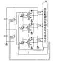
图2是示出了根据本发明的实施方式的电荷均衡设备的图示,图3是示出了图2所示的电压检测和驱动信号生成单元20的图示。FIG. 2 is a diagram showing a charge equalization device according to an embodiment of the present invention, and FIG. 3 is a diagram showing the voltage detection and driving
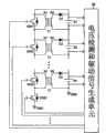
参照图2和图3,根据本发明的实施方式的电荷均衡设备包括并联地连接到N个单独串联电池B1~Bn的N个变压器T1~Tn、并联地连接到所述N个变压器T1~Tn的各个初级线圈的N个充电控制开关SW1~SWn、串联的连接到N个变压器T1~Tn的各个次级线圈的N个半导体开关元件D1~Dn、连接在第N个充电控制开关SWn与地线GND之间的重新分配开关CSW、以及电压检测和驱动信号生成单元20,所述电压检测和驱动信号生成单元20被适配为检测电池B1~Bn的电压并基于所检测的值来控制充电控制开关SW1~SWn和重新分配开关CSW的工作。2 and 3, the charge equalization device according to the embodiment of the present invention includes N transformers T1~Tn connected in parallel to N individual series batteries B1~Bn, connected in parallel to the N transformers T1~Tn N charging control switches SW1-SWn of each primary coil, N semiconductor switching elements D1-Dn connected in series to each secondary coil of N transformers T1-Tn, connected to the Nth charging control switch SWn and ground A redistribution switch CSW between the lines GND, and a voltage detection and drive
所述变压器T1~Tn并联地连接到所述N个单独串联电池B1~Bn以便降低所述N个串联电池B1~Bn之中的过充电电池的电压。The transformers T1~Tn are connected in parallel to the N individual series batteries B1~Bn in order to reduce the voltage of an overcharged battery among the N series batteries B1~Bn.
更详细地说,每个变压器T1~Tn中的次级线圈的一端连接到每个半导体开关元件D1~Dn中的阳极,且每个半导体开关元件D1~Dn的阴极连接到每个电池B1~Bn的正(+)极。每个变压器T1~Tn的次级线圈的另一端连接到每个电池B1~Bn的负(—)极。In more detail, one end of the secondary coil in each transformer T1-Tn is connected to the anode of each semiconductor switching element D1-Dn, and the cathode of each semiconductor switching element D1-Dn is connected to each battery B1-Dn. The positive (+) pole of Bn. The other end of the secondary coil of each transformer T1˜Tn is connected to the negative (−) pole of each battery B1˜Bn.
虽然变压器T1~Tn以逆向变换器型式形成,其中初级线圈和次级线圈具有相反的极性,亦即初级线圈的同名端与次级线圈的同名端位于不同侧,但是它们可以以正向变换器型式形成,其中初级线圈和次级线圈具有相同的极性。这里,每个变压器T1~Tn的初级线圈与相应的次级线圈的匝数比是同一值,亦即N1:N2。Although the transformers T1~Tn are formed as flyback converters in which the primary and secondary coils have opposite polarities, i.e. the dotted ends of the primary coils are on different sides from the dotted ends of the secondary coils, they can be transformed in the forward direction Formed in the form of a device in which the primary and secondary coils have the same polarity. Here, the turn ratios of the primary coils and the corresponding secondary coils of each of the transformers T1 - Tn are the same value, ie N1:N2.
充电控制开关SW1~SWn每个均连接在每个变压器T1~Tn的初级线圈的两端之间。响应于来自电压检测和驱动信号生成单元20的第一驱动信号,充电控制开关SW1~SWn构成旁路电路以便将从N个串联电池B1~Bn之中的一个或多个过充电电池释放的能量提供给并联地连接到除过充电电池之外的各个电池的变压器的初级线圈,并防止电流流入并联地连接到过充电电池的变压器的初级线圈。Charge control switches SW1˜SWn are each connected between both ends of the primary coils of each transformer T1˜Tn. In response to the first drive signal from the voltage detection and drive
为此,向并联地连接到过充电电池的充电控制开关提供来自电压检测和驱动信号生成单元20的高状态第一驱动信号,并向并联地连接到除过充电电池之外的电池的充电控制开关提供低状态第一驱动信号。To this end, the high-state first drive signal from the voltage detection and drive
因此,电流流过并联地连接到除过充电电池之外的电池的变压器的初级线圈,而电流不流过并联地连接到过充电电池的变压器的初级线圈,因为旁路电路由充电控制开关形成。Therefore, the current flows through the primary coil of the transformer connected in parallel to the battery other than the overcharged battery, and the current does not flow through the primary coil of the transformer connected in parallel to the overcharged battery because the bypass circuit is formed by the charge control switch .
虽然充电控制开关SW1~SWn由N型MOSFET形成,但是它们不限于N型MOSFET,而是它们每个均可以由诸如MOSFET、BJT、以及继电器等任何一种开关元件形成。Although the charging control switches SW1˜SWn are formed of N-type MOSFETs, they are not limited to N-type MOSFETs but each of them may be formed of any switching element such as MOSFET, BJT, and relay.
半导体开关元件D1~Dn每个均连接在每个变压器T1~Tn的次级线圈一端(没有点的一端)与每个电池B1~Bn的正极之间。半导体开关元件D1~Dn这样工作,即来自变压器T1~Tn的次级线圈的能量被提供到电池B1~Bn。Each of the semiconductor switching elements D1-Dn is connected between one end (the end without a dot) of the secondary coil of each transformer T1-Tn and the positive electrode of each battery B1-Bn. The semiconductor switching elements D1-Dn operate such that energy from the secondary coils of the transformers T1-Tn is supplied to the batteries B1-Bn.
虽然半导体开关元件D1~Dn由二极管形成,但是它们每个均可以由诸如MOSFET、BJT、继电器、以及二极管等任何一种开关元件形成。Although the semiconductor switching elements D1 to Dn are formed of diodes, each of them may be formed of any switching element such as MOSFET, BJT, relay, and diode.
重新分配开关CSW连接在第N个变压器Tn的初级线圈的另一端(没有同名端的一端)、第N个充电控制开关SWn的另一端(源端)、与地线GND之间,形成闭合环路,从而将从过充电电池释放的能量提供给连接到除过充电电池之外的电池的变压器的初级线圈,并用于将从非过充电变压器的初级线圈提供的能量传送到其次级线圈。The redistribution switch CSW is connected between the other end of the primary coil of the Nth transformer Tn (the end without the end of the same name), the other end (source end) of the Nth charge control switch SWn, and the ground wire GND, forming a closed loop , so that the energy discharged from the overcharged battery is supplied to the primary coil of the transformer connected to the battery other than the overcharged battery, and used to transfer the energy supplied from the primary coil of the non-overcharged transformer to its secondary coil.
换言之,重新分配开关CSW响应于来自电压检测和驱动信号生成单元20的高状态第二驱动信号而被开启并形成闭合环路,从而将过充电电池释放的能量提供给并联地连接到除过充电电池之外的电池的变压器的初级线圈。此外,重新分配开关CSW响应于来自电压检测和驱动信号生成单元20的低状态第二驱动信号而被关闭,并将存储在非过充电变压器的初级线圈中的能量传送到其次级线圈。In other words, the redistribution switch CSW is turned on in response to the high state second drive signal from the voltage detection and drive
为此,重新分配开关CSW连同充电控制开关SW1~SWn一起工作,或者在充电控制开关SW1~SWn已工作之后工作。To this end, the redistribution switch CSW operates together with the charging control switches SW1˜SWn, or operates after the charging control switches SW1˜SWn have been activated.
虽然重新分配开关CSW由N型MOSFET形成,但其不限于N型MOSFET,而是其可以由MOSFET、BJT、以及继电器等任何一种开关元件形成。Although the redistribution switch CSW is formed of N-type MOSFETs, it is not limited to N-type MOSFETs, but it may be formed of any switching elements such as MOSFETs, BJTs, and relays.
电压检测和驱动信号生成单元20检测N个串联电池B1~Bn的各个电压,将所检测的电压与基准电压进行比较,生成用于从具有高于基准电压的电压的电池(即过充电电池)释放能量的第一驱动信号和第二驱动信号,并在任何一个所检测的电压高于基准电压时对除过充电电池之外的电池充电,且向充电控制开关SW1~SWn和重新分配开关CSW提供第一和第二驱动信号。这里,所述基准电压指的是从电池B1~Bn检测到的电压的平均电压。The voltage detection and drive
这时,电压检测和驱动信号生成单元20向并联地连接到过充电电池的充电控制开关提供高状态第一驱动信号,并向并联地连接到除过充电电池之外的电池的充电控制开关提供低状态第一驱动信号。At this time, the voltage detecting and driving
此外,电压检测和驱动信号生成单元20在从过充电电池释放能量时向重新分配开关CSW提供高状态第二驱动信号,并在对除过充电电池之外的电池充电时向重新分配开关CSW提供低状态驱动信号。In addition, the voltage detection and driving
在这种情况下,电压检测和驱动信号生成单元20当在几乎所有充电控制开关被开启或电池的电荷均衡几乎完成的时侯只有少数电池被充入电荷时,向重新分配开关CSW提供基于窄的占空比脉冲宽度调制(PWM)的第二驱动信号。这种情况的原因是从一开始就从N个串联电池释放少量电荷,以便防止电流过量地流入当前正在充电的电池。In this case, the voltage detection and drive
因此,开启并联地连接到过充电电池的充电控制开关,而关闭并联地连接到除过充电电池之外的电池的充电控制开关。此外,当从过充电电池释放能量时,开启重新分配开关CSW,当对除过充电电池之外的电池充电时,关闭重新分配开关CSW。Therefore, the charge control switch connected in parallel to the overcharged battery is turned on, and the charge control switch connected in parallel to the battery other than the overcharged battery is turned off. Furthermore, the redistribution switch CSW is turned on when discharging energy from the overcharged battery, and is turned off when charging a battery other than the overcharged battery.
也就是说,当开启重新分配开关CSW时,并联地连接到过充电电池的充电控制开关形成旁路电路,因此,电流不流过并联地连接到过充电电池的变压器的初级线圈,且从过充电电池释放的能量存储在并联地连接到除过充电电池之外的电池的变压器的初级线圈中。That is, when the redistribution switch CSW is turned on, the charging control switch connected in parallel to the overcharged battery forms a bypass circuit, and therefore, current does not flow through the primary coil of the transformer connected in parallel to the overcharged battery, and flows from the overcharged battery to the overcharged battery. The energy released by the charged battery is stored in the primary coil of the transformer connected in parallel to the battery other than the overcharged battery.
此外,当关闭重新分配开关CSW时,存储在并联地连接到除过充电电池之外的电池的变压器的初级线圈中的能量被传送到其次级线圈,并对除过充电电池之外的电池充入能量。Furthermore, when the redistribution switch CSW is closed, the energy stored in the primary coil of the transformer connected in parallel to the battery other than the overcharged battery is transferred to its secondary coil and charges the battery other than the overcharged battery. into energy.
电压检测和驱动信号生成单元20同时向充电控制开关SW1~SWn和重新分配开关CSW提供第一驱动信号和第二驱动信号,或者在向充电控制开关SW1~SWn提供第一驱动信号之后向重新分配开关CSW提供第二驱动信号。The voltage detection and drive
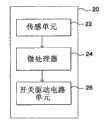
为此,电压检测和驱动信号生成单元20包括传感单元22、微处理器24、以及开关驱动电路单元26。To this end, the voltage detection and driving
传感单元22连接到各个电池B1~Bn,并检测电池B1~Bn的各个电压。The
微处理器24将由传感单元22检测的电池B1~Bn的平均电压设置为基准电压,并且如果基准电压与由传感单元22所检测的电压之一之间存在等于或大于预定值的差,则设置用于电池充电/放电的充电控制开关SW1~SWn和重新分配开关CSW的开/关时间。The
开关驱动电路单元26响应于来自微处理器24的信号而生成第一驱动信号和第二驱动信号,并将所生成的信号提供给充电控制开关SW1~SWn和重新分配开关CSW。The switch
在根据本发明的本实施方式的电荷均衡设备中,无论N个串联电池B1~Bn的数目多少,小容量变压器都被并联地连接到串联电池B1~Bn,从而不仅可以保持优良的电荷均衡特性,而且还可以容易地制造变压器的初级和次级线圈。In the charge equalization device according to the present embodiment of the present invention, regardless of the number of N series batteries B1~Bn, small-capacity transformers are connected in parallel to the series batteries B1~Bn, so that not only excellent charge balance characteristics can be maintained , but also the primary and secondary coils of the transformer can be easily fabricated.
此外,根据本发明的本实施方式的电荷均衡设备借助于并联地连接到变压器T1~Tn的初级线圈的充电控制开关SW1~SWn根据N个串联电池B1~Bn的各个充电状态来控制充入电池的电荷流。In addition, the charge equalization device according to the present embodiment of the present invention controls the charging of the batteries according to the respective states of charge of the N series batteries B1 to Bn by means of the charging control switches SW1˜SWn connected in parallel to the primary coils of the transformers T1˜Tn. the charge flow.
最后,根据本发明的本实施方式的电荷均衡设备可以通过当过电流在电池的电荷均衡几乎完成或几乎所有充电控制开关被开启的时候流入少数电池时控制被施加于重新分配开关CSW的第二驱动信号的PWM占空比来防止过电流流入当前正在充电的电池。Finally, the charge equalization device according to the present embodiment of the present invention can control the second voltage applied to the redistribution switch CSW by controlling when an overcurrent flows into a small number of batteries when the charge equalization of the batteries is almost completed or almost all the charge control switches are turned on. The PWM duty cycle of the driving signal is used to prevent excessive current from flowing into the battery that is currently being charged.
下面描述根据本发明的本实施方式的使用电荷均衡设备来使串联电池电压均衡的方法。A method of using a charge equalization device to equalize voltages of series-connected batteries according to the present embodiment of the present invention will be described below.
首先,电压检测和驱动信号生成单元20检测N个串联电池B1~Bn的各个电压。First, the voltage detection and drive
这时,当从所述N个串联电池B1~Bn中的一个或多个检测到高于基准电压的一个或多个电压时,电压检测和驱动信号生成单元20生成用于驱动并联地连接到过充电电池的充电控制开关以便从过充电电池释放能量的第一驱动信号,并将该第一驱动信号提供给充电控制开关。At this time, when one or more voltages higher than the reference voltage are detected from one or more of the N series batteries B1˜Bn, the voltage detection and driving
例如,当除第一电池B1和第N电池Bn之外的电池被过量充电时,电压检测和驱动信号生成单元20向并联地连接到第一电池B1和第N电池Bn的充电控制开关SW1和SWn提供低状态第一驱动信号,并向并联地连接到除第一电池B1和第N电池Bn之外的电池的充电控制开关提供高状态第一驱动信号。For example, when batteries other than the first battery B1 and the Nth battery Bn are overcharged, the voltage detection and drive
这时,电压检测和驱动信号生成单元20向重新分配开关CSW提供高状态第二驱动信号。At this time, the voltage detection and driving
因此,如图4所示,从过充电的电池释放的电荷被转换成磁能并随后存储在并联地连接到第一电池B1和第N电池Bn的变压器T1和Tn的初级线圈中,并联地连接到除第一电池B1和第N电池Bn之外的电池的充电控制开关形成旁路电路,因此,电流不流过并联地连接到除第一电池B1和第N电池Bn之外的电池的变压器的初级线圈。Therefore, as shown in FIG. 4, the charge discharged from the overcharged battery is converted into magnetic energy and then stored in the primary coils of the transformers T1 and Tn connected in parallel to the first battery B1 and the Nth battery Bn, which are connected in parallel The charging control switch to the batteries other than the first battery B1 and the Nth battery Bn forms a bypass circuit, and therefore, current does not flow through the transformer connected in parallel to the batteries other than the first battery B1 and the Nth battery Bn the primary coil.
其后,电压检测和驱动信号生成单元20向重新分配开关CSW提供低状态第二驱动信号,从而关闭重新分配开关CSW。Thereafter, the voltage detection and driving
因此,如图5所示,生成了反电动势,因此,存储在并联地连接到第一电池B1和第N电池Bn的变压器T1和Tn的初级线圈中的能量被传送到其次级线圈并随后转换成电荷,而且该电荷经由串联地连接到其次级线圈的半导体开关元件D1和Dn而被提供给除过充电电池之外的电池。因此,除过充电电池之外的电池被充入经由半导体开关元件D1和Dn而提供的电荷。Therefore, as shown in FIG. 5, a back electromotive force is generated, and therefore, energy stored in the primary coils of the transformers T1 and Tn connected in parallel to the first battery B1 and the Nth battery Bn is transferred to its secondary coil and then converted is charged, and the charge is supplied to the battery other than the overcharged battery via the semiconductor switching elements D1 and Dn connected in series to its secondary coil. Accordingly, the batteries other than the overcharged battery are charged with the charges supplied via the semiconductor switching elements D1 and Dn.
重复上述处理直到使N个串联电池B1~Bn的电压均衡。为此,电压检测和驱动信号生成单元20连续地检测N个串联电池B1~Bn的电压,生成第一驱动信号和第二驱动信号,并将该第一和第二驱动信号提供给充电控制开关SW1~SWn和重新分配开关CSW。The above processing is repeated until the voltages of the N series batteries B1 to Bn are equalized. To this end, the voltage detection and driving
图6是示出了根据本发明的另一实施方式的电荷均衡设备的图示。FIG. 6 is a diagram showing a charge equalization device according to another embodiment of the present invention.
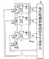
参照图6,根据本发明的另一实施方式的电荷均衡设备包括并联地连接到N个单独串联电池B1~Bn的N个变压器T1~Tn、并联地连接到所述N个变压器T1~Tn的各个初级线圈的N个充电控制开关SW1~SWn、每个均串联地连接到每个变压器T1~Tn的次级线圈的第一半导体开关元件D11~Dn1和电感器L1~Ln、每个均连接在每个电池B1~Bn的负极与每个第一半导体开关元件D11~Dn1和每个电感器L1~Ln的公共节点之间的第二半导体开关元件D11~Dn1、连接在第N个充电控制开关SWn与地线GND之间的重新分配开关CSW、以及电压检测和驱动信号生成单元30,该电压检测和驱动信号生成单元30被适配为检测电池B1~Bn的电压并基于所检测的值来控制充电控制开关SW1~SWn和重新分配开关CSW的工作。Referring to FIG. 6, a charge equalization device according to another embodiment of the present invention includes N transformers T1~Tn connected in parallel to N individual series batteries B1~Bn, and N transformers T1~Tn connected in parallel to the N transformers T1~Tn. The N charging control switches SW1 to SWn of the respective primary coils are each connected in series to the first semiconductor switching elements D11 to Dn1 of the secondary coils of each of the transformers T1 to Tn and the inductors L1 to Ln are each connected to The second semiconductor switching elements D11 to Dn1 between the negative electrodes of each of the batteries B1 to Bn and the common nodes of each of the first semiconductor switching elements D11 to Dn1 and each of the inductors L1 to Ln are connected to the Nth charging control A redistribution switch CSW between the switch SWn and the ground GND, and a voltage detection and drive
变压器T1~Tn并联地连接到N个单独串联电池B1~Bn以便降低N个串联电池B1~Bn之中的过充电电池的电压。The transformers T1~Tn are connected in parallel to the N individual series batteries B1~Bn in order to reduce the voltage of the overcharged battery among the N series batteries B1~Bn.
更详细地说,每个变压器T1~Tn的次级线圈的一端连接到每个半导体开关元件D11~Dn1的阳极,每个半导体开关元件D11到Dn1的阴极连接到每个电感器L1~Ln的一端,且每个电感器L1~Ln的另一端连接到每个电池B1~Bn的正(+)极。此外,每个变压器T1~Tn的次级线圈的另一端连接到每个电池B1~Bn的负(—)极。In more detail, one end of the secondary coil of each transformer T1-Tn is connected to the anode of each semiconductor switching element D11-Dn1, and the cathode of each semiconductor switching element D11-Dn1 is connected to each of the inductors L1-Ln. One terminal, and the other terminal of each inductor L1˜Ln is connected to the positive (+) pole of each battery B1˜Bn. In addition, the other end of the secondary coil of each transformer T1˜Tn is connected to the negative (−) pole of each battery B1˜Bn.
虽然变压器T1~Tn以前向变换器型式形成,其中初级线圈和次级线圈具有相同的极性,亦即初级线圈的同名端与次级线圈的同名端位于同侧,但是它们可以以逆向变换器型式形成。这里,每个变压器T1~Tn的初级线圈与相应的次级线圈的匝数比是N1:N2。Although the transformers T1~Tn are formed in a forward converter type in which the primary coil and the secondary coil have the same polarity, that is, the same-named end of the primary coil and the same-named end of the secondary coil are on the same side, but they can be used as a reverse converter Formation. Here, the turns ratio of the primary coil to the corresponding secondary coil of each of the transformers T1 ˜ Tn is N1 : N2 .
充电控制开关SW1~SWn每个均连接在每个变压器T1~Tn的初级线圈的两端之间。响应于来自电压检测和驱动信号生成单元30的第一驱动信号,充电控制开关SW1~SWn将从N个串联电池B1~Bn之中的一个或多个过充电电池释放的能量提供给并联地连接到除过充电电池之外的各个电池的变压器的初级线圈,并形成旁路电路以使电流不流入并联地连接到过充电电池的变压器的初级线圈。Charge control switches SW1˜SWn are each connected between both ends of the primary coils of each transformer T1˜Tn. In response to the first drive signal from the voltage detection and drive
为此,向并联地连接到过充电电池的充电控制开关提供来自电压检测和驱动信号生成单元30的高状态第一驱动信号,并向并联地连接到除过充电电池之外的电池的充电控制开关提供低状态第一驱动信号。To this end, the high-state first drive signal from the voltage detection and drive
因此,电流流过并联地连接到除过充电电池之外的电池的变压器的初级线圈,而电流不流过并联地连接到过充电电池的变压器的初级线圈,因为旁路电路由充电控制开关形成。Therefore, the current flows through the primary coil of the transformer connected in parallel to the battery other than the overcharged battery, and the current does not flow through the primary coil of the transformer connected in parallel to the overcharged battery because the bypass circuit is formed by the charge control switch .
虽然充电控制开关SW1~SWn由N型MOSFET形成,但是它们不限于N型MOSFET,而且它们每个均可以由诸如MOSFET、BJT、以及继电器等任何一种开关元件形成。Although the charging control switches SW1 to SWn are formed of N-type MOSFETs, they are not limited to N-type MOSFETs, and each of them may be formed of any switching element such as MOSFET, BJT, and relay.
第一半导体开关元件D11~Dn1每个均连接在每个变压器T1~Tn的次级线圈的一端(形成同名端的一端)与每个电感器L1~Ln之间,并进行工作,以使得来自变压器T1~Tn的次级线圈的能量被提供给电池B1~Bn。Each of the first semiconductor switching elements D11 to Dn1 is connected between one end of the secondary coil of each of the transformers T1 to Tn (the end forming the end of the same name) and each of the inductors L1 to Ln, and operates so that The energy of the secondary coils of T1 to Tn is supplied to batteries B1 to Bn.
虽然第一半导体开关元件D11~Dn1由二极管形成,但它们不限于二极管,而是每个均可以由诸如MOSFET、BJT、继电器、以及二极管等任何一种开关元件形成。Although the first semiconductor switching elements D11 to Dn1 are formed of diodes, they are not limited to diodes but each may be formed of any switching element such as MOSFET, BJT, relay, and diode.
电感器L1~Ln每个均连接在每个第一半导体开关元件D11~Dn1的阴极与每个电池B1~Bn的正极之间。电感器L1~Ln在重新分配开关CSW被开启时存储来自变压器T1~Tn的次级线圈的能量,并在重新分配开关CSW被关闭时将存储的能量提供给电池B1~Bn。Each of the inductors L1˜Ln is connected between the cathode of each first semiconductor switching element D11˜Dn1 and the anode of each battery B1˜Bn. The inductors L1˜Ln store energy from the secondary coils of the transformers T1˜Tn when the redistribution switch CSW is turned on, and supply the stored energy to the batteries B1˜Bn when the redistribution switch CSW is turned off.
第二半导体开关元件D12~Dn2每个均连接在每个电池B1~Bn的负极与每个第一半导体开关元件D11~Dn1和每个电感器L1~Ln的公共节点之间,并形成闭合环路,以便将存储在电感器L1~Ln中的能量提供给电池B1~Bn。Each of the second semiconductor switching elements D12-Dn2 is connected between the negative pole of each battery B1-Bn and the common node of each first semiconductor switching element D11-Dn1 and each inductor L1-Ln, and forms a closed loop In order to provide the energy stored in the inductors L1~Ln to the batteries B1~Bn.
为此,每个第二半导体开关元件D12~Dn2的阳极连接到每个电池B1~Bn的负极,且其阴极连接到每个第一半导体开关元件D11~Dn1的阴极。For this, the anode of each second semiconductor switching element D12Dn2 is connected to the negative electrode of each battery B1Bn, and the cathode thereof is connected to the cathode of each first semiconductor switching element D11Dn1.
虽然第二半导体开关元件D12~Dn2由二极管形成,但它们不限于二极管,而是每个均可以由诸如MOSFET、BJT、继电器、以及二极管等任何一种开关元件形成。Although the second semiconductor switching elements D12 to Dn2 are formed of diodes, they are not limited to diodes but each may be formed of any switching element such as MOSFET, BJT, relay, and diode.
重新分配开关CSW连接在第N个变压器Tn的初级线圈的另一端(没有形成同名端的一端)与地线GND之间,形成闭合环路以便经由并联地连接到除过充电电池之外的电池的变压器将从过充电电池释放的能量提供给除过充电电池之外的电池,并允许将存储在电感器L1~Ln中的能量提供给除过充电电池之外的电池。The redistribution switch CSW is connected between the other end of the primary coil of the N-th transformer Tn (the end not forming the end of the same name) and the ground GND to form a closed loop so as to be connected in parallel to the battery other than the overcharged battery. The transformer supplies energy discharged from the overcharged battery to batteries other than the overcharged battery, and allows energy stored in the inductors L1˜Ln to be supplied to batteries other than the overcharged battery.
换言之,重新分配开关CSW响应于来自电压检测和驱动信号生成单元30的高状态第二驱动信号而被开启,并形成闭合环路,以便将从过充电电池释放的能量提供给并联地连接到除过充电电池之外的电池的变压器的初级线圈。In other words, the redistribution switch CSW is turned on in response to the high-state second drive signal from the voltage detection and drive
因此,存储在并联地连接到除过充电电池之外的电池的变压器的初级线圈中的能量被传送到其次级线圈,并经由第一半导体开关元件D11和Dn1及电感器L1~Ln而被提供给除过充电电池之外的电池。因此,除过充电电池之外的电池被充电。Therefore, the energy stored in the primary coil of the transformer connected in parallel to the battery other than the overcharged battery is transferred to its secondary coil and supplied via the first semiconductor switching elements D11 and Dn1 and the inductors L1˜Ln For batteries other than overcharged batteries. Therefore, batteries other than the overcharged battery are charged.
此外,重新分配开关CSW响应于来自电压检测和驱动信号生成单元30的低状态第二驱动信号而被关闭,在电感器L1~Ln中生成反电动势,并允许对除过充电电池之外的电池充入存储在电感器L1~Ln中的能量。In addition, the redistribution switch CSW is turned off in response to the low-state second drive signal from the voltage detection and drive
重新分配开关CSW连同充电控制开关SW1~SWn一起工作,或者在充电控制开关SW1~SWn已工作之后工作。The redistribution switch CSW operates together with the charging control switches SW1-SWn, or after the charging control switches SW1-SWn have been operated.
虽然重新分配开关CSW由N型MOSFET形成,但其不限于N型MOSFET,而是其可以由MOSFET、BJT、以及继电器等任何一种开关元件形成。Although the redistribution switch CSW is formed of N-type MOSFETs, it is not limited to N-type MOSFETs, but it may be formed of any switching elements such as MOSFETs, BJTs, and relays.
电压检测和驱动信号生成单元30检测N个串联电池B1~Bn的各个电压,将所检测的电压与基准电压进行比较,生成用于从具有比基准电压更高的电压的电池(即过充电电池)释放能量的第一驱动信号和第二驱动信号,并且如果任何一个所检测的电压高于基准电压,则对除过充电电池之外的电池充电,并向充电控制开关SW1~SWn和重新分配开关CSW提供第一和第二驱动信号。The voltage detection and drive
这时,电压检测和驱动信号生成单元30向并联地连接到过充电电池的充电控制开关提供高状态第一驱动信号,并向并联地连接到除过充电电池之外的电池的充电控制开关提供低状态第一驱动信号。At this time, the voltage detecting and driving
此外,电压检测和驱动信号生成单元30在从过充电电池释放能量并对除过充电电池之外的电池充入所述能量时向重新分配开关CSW提供高状态第二驱动信号,并在对除过充电电池之外的电池充入存储在电感器L1~Ln中的能量时向重新分配开关CSW提供低状态第二驱动信号。In addition, the voltage detecting and driving
在这种情况下,电压检测和驱动信号生成单元30在只有少数电池在几乎所有充电控制开关被开启或电池的电荷均衡几乎完成的时候被充入电荷时,向重新分配开关CSW提供基于窄的占空比脉冲宽度调制(PWM)的第二驱动信号。这种情况的原因是从一开始就从N个串联电池释放少量电荷,以便防止电流过量地流入当前正在充电的电池。In this case, the voltage detection and drive
因此,开启并联地连接到过充电电池的充电控制开关,而关闭并联地连接到除过充电电池之外的电池的充电控制开关。此外,当从过充电电池释放能量并对除过充电电池之外的电池充入该能量时,开启重新分配开关CSW,当对除过充电电池之外的电池充电时,关闭重新分配开关CSW。Therefore, the charge control switch connected in parallel to the overcharged battery is turned on, and the charge control switch connected in parallel to the battery other than the overcharged battery is turned off. Also, the redistribution switch CSW is turned on when discharging energy from the overcharged battery and charging the energy to a battery other than the overcharged battery, and is turned off when charging a battery other than the overcharged battery.
也就是说,当开启重新分配开关CSW时,并联地连接到过充电电池的充电控制开关形成旁路电路,从而电流不流过并联地连接到过充电电池的变压器的初级线圈,且从过充电电池释放的电荷被转换成磁能并随后存储在并联地连接到除过充电电池之外的电池的变压器的初级线圈中。此外,存储在并联地连接到除过充电电池之外的电池的变压器的初级线圈中的能量被传送到并联地连接到除过充电电池之外的电池的变压器的次级线圈,且传送到次级线圈的磁能被转换成电荷,并经由第一半导体开关元件和电感器来对除过充电电池之外的电池充电。That is, when the redistribution switch CSW is turned on, the charge control switch connected in parallel to the overcharged battery forms a bypass circuit so that current does not flow through the primary coil of the transformer connected in parallel to the overcharged battery, and from the overcharged battery The charge discharged by the battery is converted into magnetic energy and then stored in the primary coil of a transformer connected in parallel to the battery other than the overcharged battery. In addition, the energy stored in the primary coil of the transformer connected in parallel to the battery other than the overcharged battery is transferred to the secondary coil of the transformer connected in parallel to the battery other than the overcharged battery, and transferred to the secondary The magnetic energy of the stage coil is converted into electric charge, and charges the battery other than the overcharged battery via the first semiconductor switching element and the inductor.
此外,当关闭重新分配开关CSW时,对除过充电电池之外的电池充入存储在电感器中的能量。Also, when the redistribution switch CSW is turned off, batteries other than the overcharged battery are charged with the energy stored in the inductor.
电压检测和驱动信号生成单元30同时向充电控制开关SW1~SWn和重新分配开关CSW提供第一驱动信号和第二驱动信号,或者在向充电控制开关SW1~SWn提供第一驱动信号之后向重新分配开关CSW提供第二驱动信号。The voltage detection and drive
为此,如图3所示,电压检测和驱动信号生成单元30包括传感单元22、微处理器24、以及开关驱动电路单元26。To this end, as shown in FIG. 3 , the voltage detection and driving
传感单元22连接到各个电池B1~Bn,并检测电池B1~Bn各自的电压。The
微处理器24将由传感单元22检测的电池B1~Bn的平均电压设置为基准电压,并且当基准电压与由传感单元22所检测的电压之一之间存在等于或高于预定值的差时,为了电池充电/放电而设置充电控制开关SW1~SWn和重新分配开关CSW的开/关时间。The
开关驱动电路单元26响应于来自微处理器24的信号而生成第一驱动信号和第二驱动信号,并将所生成的信号提供给充电控制开关SW1~SWn和重新分配开关CSW。The switch
在根据本发明的实施方式的电荷均衡设备中,无论N个串联电池B1~Bn的数目多少,小容量变压器都被并联地连接到各个串联电池B1~Bn,因此不仅可以保持优良的电荷均衡特性,而且还可以容易地制造变压器的初级和次级线圈。In the charge equalization device according to the embodiment of the present invention, regardless of the number of N series batteries B1˜Bn, small-capacity transformers are connected in parallel to each series series batteries B1˜Bn, so that not only excellent charge equalization characteristics can be maintained , but also the primary and secondary coils of the transformer can be easily fabricated.
此外,根据本发明的本实施方式的电荷均衡设备借助于并联地连接到变压器T1~Tn的初级线圈的充电控制开关SW1~SWn,根据N个串联电池B1~Bn的各个充电状态来控制充入电池的电荷流。In addition, the charge equalization device according to the present embodiment of the present invention controls the charge-in according to the respective charge states of the N series-connected batteries B1-Bn by means of the charge control switches SW1-SWn connected in parallel to the primary coils of the transformers T1-Tn. The charge flow of the battery.
最后,根据本发明的本实施方式的电荷均衡设备可以通过当过电流在电池的电荷均衡几乎完成时或几乎所有充电控制开关被开启的时候流入少数电池时控制被施加于重新分配开关CSW的第二驱动信号的PWM占空比来防止过电流流入当前正在充电的电池。Finally, the charge equalization device according to the present embodiment of the present invention can control the first charge applied to the redistribution switch CSW by controlling when an overcurrent flows into a small number of batteries when the charge equalization of the batteries is almost completed or when almost all the charge control switches are turned on. The PWM duty cycle of the second drive signal prevents overcurrent from flowing into the battery that is currently being charged.
下面描述根据本发明的本实施方式的使用电荷均衡设备来使串联电池电压均衡的方法。A method of using a charge equalization device to equalize voltages of series-connected batteries according to the present embodiment of the present invention will be described below.
首先,电压检测和驱动信号生成单元30检测N个串联电池B1~Bn的各个电压。First, the voltage detection and drive
这时,当从所述N个串联电池B1~Bn中的一个或多个检测到高于基准电压的一个或多个电压时,电压检测和驱动信号生成单元30生成用于驱动并联地连接到过充电电池的充电控制开关以便从过充电电池释放能量的第一驱动信号,并将该第一驱动信号提供给充电控制开关。At this time, when one or more voltages higher than the reference voltage are detected from one or more of the N series batteries B1˜Bn, the voltage detection and driving
例如,当除第一电池B1和第N电池Bn之外的电池被过量充电时,电压检测和驱动信号生成单元30向并联地连接到第一电池B1和第N电池Bn的充电控制开关SW1和SWn提供低状态第一驱动信号,并向并联地连接到除第一电池B1和第N电池Bn之外的电池的充电控制开关提供高状态第一驱动信号。For example, when batteries other than the first battery B1 and the Nth battery Bn are overcharged, the voltage detection and drive
此外,电压检测和驱动信号生成单元30向重新分配开关CSW提供高状态第二驱动信号。In addition, the voltage detection and driving
因此,如图7所示,从过充电的电池释放的电荷被转换成磁能并随后存储在并联地连接到第一电池B1和第N电池Bn的变压器T1和Tn的初级线圈中,并联地连接到除第一电池B1和第N电池Bn之外的电池的充电控制开关形成旁路电路,因此,电流不流过并联地连接到除第一电池B1和第N电池Bn之外的电池的变压器的初级线圈。Therefore, as shown in FIG. 7, the charge discharged from the overcharged battery is converted into magnetic energy and then stored in the primary coils of the transformers T1 and Tn connected in parallel to the first battery B1 and the Nth battery Bn, which are connected in parallel The charging control switch to the batteries other than the first battery B1 and the Nth battery Bn forms a bypass circuit, and therefore, current does not flow through the transformer connected in parallel to the batteries other than the first battery B1 and the Nth battery Bn the primary coil.
这时,存储在并联地连接到第一电池B1和第N电池Bn的变压器T1和Tn的初级线圈中的能量被传送到其次级线圈,且传送到次级线圈的磁能被转换为电荷,并且第一电池B1和第N电池Bn经由第一半导体开关元件D11和Dn1及电感器L1和Ln而被充入所述电荷。此外,经由次级线圈而提供的电荷被转换成磁能并随后存储在电感器L1和Ln中。At this time, the energy stored in the primary coils of the transformers T1 and Tn connected in parallel to the first battery B1 and the Nth battery Bn is transmitted to its secondary coil, and the magnetic energy transmitted to the secondary coil is converted into electric charge, and The first battery B1 and the Nth battery Bn are charged with the charges via the first semiconductor switching elements D11 and Dn1 and the inductors L1 and Ln. In addition, charges supplied via the secondary coil are converted into magnetic energy and then stored in the inductors L1 and Ln.
其后,电压检测和驱动信号生成单元30向重新分配开关CSW提供低状态第二驱动信号,从而关闭重新分配开关CSW。Thereafter, the voltage detection and driving
因此,如图8所示,存储在电感器L1和Ln中的磁能被反电动势转换成电荷,且第一电池B1和第N电池Bn使用所述电荷进行充电。Therefore, as shown in FIG. 8 , the magnetic energy stored in the inductors L1 and Ln is converted into charges by the counter electromotive force, and the first battery B1 and the Nth battery Bn are charged using the charges.
重复上述处理直到使N个串联电池B1~Bn的电压均衡。为此,电压检测和驱动信号生成单元30连续地检测N个串联电池B1~Bn的电压,生成第一驱动信号和第二驱动信号,并将该第一和第二驱动信号提供给充电控制开关SW1~SWn和重新分配开关CSW。The above processing is repeated until the voltages of the N series batteries B1 to Bn are equalized. To this end, the voltage detection and driving
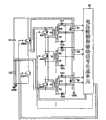
图9是示出了根据本发明的另一实施方式的电荷均衡设备的图示。FIG. 9 is a diagram showing a charge equalization device according to another embodiment of the present invention.
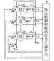
参照图9,根据本发明的实施方式的电荷均衡设备包括并联地连接到N个单独串联电池B1~Bn的N个变压器T1~Tn、第一电荷存储装置C1、第二电荷存储装置C2、第一重新分配开关CSW1、第二重新分配开关CSW2、并联地连接到所述N个变压器T1~Tn的各个初级线圈的N个充电控制开关SW1~SWn、串联地连接到所述N个变压器T1~Tn的各个第一次级线圈的第一半导体开关元件D11到Dn1、串联地连接到所述N个变压器T1~Tn的各个第二次级线圈的第二半导体开关元件D12~Dn2、以及电压检测和驱动信号生成单元40,该电压检测和驱动信号生成单元40被适配为检测电池B1~Bn的电压并基于所检测的值来控制充电控制开关SW1~SWn和重新分配开关CSW的工作。Referring to FIG. 9 , a charge equalization device according to an embodiment of the present invention includes N transformers T1~Tn connected in parallel to N individual series batteries B1~Bn, a first charge storage device C1, a second charge storage device C2, a first charge storage device C2, and a second charge storage device C2. A redistribution switch CSW1, a second redistribution switch CSW2, N charging control switches SW1˜SWn connected in parallel to the respective primary coils of the N transformers T1˜Tn, connected in series to the N transformers T1˜Tn The first semiconductor switching elements D11 to Dn1 of the respective first secondary coils of Tn, the second semiconductor switching elements D12 to Dn2 of the respective second secondary coils of the N transformers T1 to Tn connected in series, and the voltage detection and a driving
变压器T1~Tn并联地连接到N个单独串联电池B1到Bn以便降低N个串联电池B1~Bn之中的过充电电池的电压并对除过充电电池之外的电池充电。The transformers T1~Tn are connected in parallel to the N individual series batteries B1~Bn in order to lower the voltage of overcharged batteries among the N series batteries B1~Bn and to charge batteries other than the overcharged batteries.
更详细地说,每个变压器T1~Tn的第一次级线圈的一端(形成同名端的一端)连接到每个第一半导体开关元件D11~Dn1的阳极,第二次级线圈的另一端(没有形成同名端的一端)连接到每个第二半导体开关元件D12~Dn2的阳极,且每个第一半导体开关元件D11~Dn1和第二半导体开关元件D12~Dn2的阴极连接到每个电池B1~Bn的正极。In more detail, one end of the first secondary coil of each of the transformers T1˜Tn (the end forming the terminal of the same name) is connected to the anode of each of the first semiconductor switching elements D11˜Dn1, and the other end of the second secondary coil (without One terminal forming the end of the same name) is connected to the anode of each second semiconductor switching element D12~Dn2, and the cathode of each first semiconductor switching element D11~Dn1 and the second semiconductor switching element D12~Dn2 is connected to each battery B1~Bn positive pole.
此外,变压器T1~Tn的每个第一次级线圈的另一端和每个第二次级线圈的一端连接到每个电池B1~Bn的负极,且每个充电控制开关SW1~SWn连接到每个初级线圈的两端。In addition, the other end of each first secondary coil and one end of each second secondary coil of transformers T1˜Tn are connected to the negative pole of each battery B1˜Bn, and each charge control switch SW1˜SWn is connected to each both ends of the primary coil.
变压器T1~Tn以半桥式变换器型式形成,其中,初级线圈、第一次级线圈和第二次级线圈具有相同的极性,亦即初级线圈的同名端及第一和第二次级线圈的同名端位于相同侧,且每个次级线圈分成两个线圈。The transformers T1~Tn are formed in the form of a half-bridge converter, in which the primary coil, the first secondary coil and the second secondary coil have the same polarity, that is, the same-named terminals of the primary coil and the first and second secondary coils The dotted ends of the coils are on the same side, and each secondary coil is split into two coils.
在这种情况下,每个变压器T1到Tn的初级线圈与其次级线圈的匝数比是N1:N2,且第一次级线圈和第二次级线圈具有相同的匝数比。In this case, the turn ratio of the primary coil to its secondary coil of each of the transformers T1 to Tn is N1:N2, and the first secondary coil and the second secondary coil have the same turn ratio.
第一电荷存储装置C1和第二电荷存储装置C2每个均并联地连接到N个串联电池B1~Bn和变压器T1~Tn,并存储从N个串联电池B1~Bn提供的电荷。The first charge storage device C1 and the second charge storage device C2 are each connected in parallel to the N series batteries B1Bn and the transformers T1Bn, and store charges supplied from the N series batteries B1Bn.
虽然第一电荷存储装置C1和第二电荷存储装置C2由电容器形成,但它们每个均可以由电容器和蓄电池中的任何一个形成。此外,第一电荷存储装置C1和第二电荷存储装置C2具有相同的容量。Although the first charge storage means C1 and the second charge storage means C2 are formed of capacitors, each of them may be formed of any one of capacitors and storage batteries. In addition, the first charge storage device C1 and the second charge storage device C2 have the same capacity.
第一重新分配开关CSW1和第二重新分配开关CSW2每个均并联地连接在电池B1~Bn与每个电荷存储装置C1和C2之间,并响应于来自电压检测和驱动信号生成单元40而生成闭合环路以便从N个串联电池B1~Bn之中的过充电电池释放能量并对除过充电电池之外的电池充电。Each of the first redistribution switch CSW1 and the second redistribution switch CSW2 is connected in parallel between the batteries B1˜Bn and each of the charge storage devices C1 and C2, and generates The loop is closed to discharge energy from the overcharged battery among the N series batteries B1-Bn and to charge the batteries other than the overcharged battery.
第一重新分配开关CSW1和第二重新分配开关CSW2在从电压检测和驱动信号生成单元40提供高状态第二驱动信号时被开启,并在从其提供低状态第二驱动信号时被关闭。The first redistribution switch CSW1 and the second redistribution switch CSW2 are turned on when a high state second driving signal is supplied from the voltage detection and driving
也就是说,当从过充电电池释放能量并对除过充电电池之外的电池充电时,第二重新分配开关CSW2在第一重新分配开关CSW1被开启时被关闭,且第二重新分配开关CSW2在第一重新分配开关CSW1被关闭时被开启。That is, when discharging energy from the overcharged battery and charging a battery other than the overcharged battery, the second redistribution switch CSW2 is turned off while the first redistribution switch CSW1 is turned on, and the second redistribution switch CSW2 is turned on when the first reallocation switch CSW1 is turned off.
第一重新分配开关CSW1和第二重新分配开关CSW2串联地连接在第一电池B1的正极与地线GND之间。此外,第一重新分配开关CSW1与第二重新分配开关CSW2之间的公共节点连接到第一变压器T1的初级线圈的一端。The first redistribution switch CSW1 and the second redistribution switch CSW2 are connected in series between the positive electrode of the first battery B1 and the ground GND. In addition, a common node between the first redistribution switch CSW1 and the second redistribution switch CSW2 is connected to one end of the primary coil of the first transformer T1.
虽然第一重新分配开关CSW1和第二重新分配开关CSW2由N型MOSFET形成,但是它们每个均可以由诸如MOSFET、BJT、以及继电器等任何一种开关元件形成。Although the first redistribution switch CSW1 and the second redistribution switch CSW2 are formed of N-type MOSFETs, each of them may be formed of any kind of switching elements such as MOSFETs, BJTs, and relays.
充电控制开关SW1~SWn每个均连接在每个变压器T1~Tn的初级线圈的两端之间。响应于来自电压检测和驱动信号生成单元40的第一驱动信号,充电控制开关SW1~SWn构成旁路电路以便将从N个串联电池B1~Bn之中的一个或多个过充电电池释放的能量提供给并联地连接到除过充电电池之外的各个电池的变压器的初级线圈,并防止电流流入并联地连接到过充电电池的变压器的初级线圈。Charge control switches SW1˜SWn are each connected between both ends of the primary coils of each transformer T1˜Tn. In response to the first drive signal from the voltage detection and drive
为此,向并联地连接到过充电电池的充电控制开关提供来自电压检测和驱动信号生成单元40高状态第一驱动信号,并向并联地连接到除过充电电池之外的电池的充电控制开关提供低状态第一驱动信号。To this end, the high-state first drive signal from the voltage detection and drive
因此,电流流过并联地连接到除过充电电池之外的电池的变压器的初级线圈,而电流不流过并联地连接到过充电电池的变压器的初级线圈,因为旁路电路由充电控制开关形成。Therefore, the current flows through the primary coil of the transformer connected in parallel to the battery other than the overcharged battery, and the current does not flow through the primary coil of the transformer connected in parallel to the overcharged battery because the bypass circuit is formed by the charge control switch .
虽然充电控制开关SW1~SWn由N型MOSFET形成,但是它们不限于N型MOSFET,而是它们每个均可以由诸如MOSFET、BJT、以及继电器等任何一种开关元件形成。Although the charging control switches SW1˜SWn are formed of N-type MOSFETs, they are not limited to N-type MOSFETs but each of them may be formed of any switching element such as MOSFET, BJT, and relay.
第一半导体开关元件D11~Dn1每个均连接在每个变压器T1~Tn的第一次级线圈的一端(形成同名端的一端)与每个电池B1~Bn的正极之间,并进行工作,以使得来自变压器T1~Tn的第一次级线圈的能量被提供给电池B1~Bn。Each of the first semiconductor switching elements D11-Dn1 is connected between one end of the first secondary coil of each transformer T1-Tn (the end forming the end of the same name) and the positive pole of each battery B1-Bn, and operates to The energy from the first secondary coils of the transformers T1-Tn is supplied to the batteries B1-Bn.
第二半导体开关元件D12~Dn2每个均连接在每个变压器T1~Tn的第一次级线圈的另一端(没有形成同名端的一端)与每个电池B1~Bn的正极之间,并进行工作,以使得来自变压器T1~Tn的第二次级线圈的能量被提供给电池B1~Bn。Each of the second semiconductor switching elements D12-Dn2 is connected between the other end of the first secondary coil of each transformer T1-Tn (the end not forming the end with the same name) and the positive pole of each battery B1-Bn, and operates , so that the energy from the second secondary coils of the transformers T1-Tn is supplied to the batteries B1-Bn.
虽然第一半导体开关元件D11~Dn1由二极管形成,但它们不限于二极管,而是每个均可以由诸如MOSFET、BJT、继电器、以及二极管等任何一种开关元件形成。Although the first semiconductor switching elements D11 to Dn1 are formed of diodes, they are not limited to diodes but each may be formed of any switching element such as MOSFET, BJT, relay, and diode.
电压检测和驱动信号生成单元40检测N个串联电池B1~Bn的各个电压,将所检测的电压与基准电压进行比较,生成用于从具有比基准电压更高的电压的电池(即过充电电池)释放能量的第一驱动信号和第二驱动信号,并且如果任何一个所检测的电压高于基准电压,则对除过充电电池之外的电池充电,并向充电控制开关SW1~SWn、第一重新分配开关CSW1、以及第二重新分配开关CSW2提供所述第一和第二驱动信号。The voltage detection and drive
这时,电压检测和驱动信号生成单元40向并联地连接到过充电电池的充电控制开关提供高状态第一驱动信号,并向并联地连接到除过充电电池之外的电池的充电控制开关提供低状态第一驱动信号。At this time, the voltage detecting and driving
此外,电压检测和驱动信号生成单元40在从过充电电池释放能量并对除过充电电池之外的电池充入该能量时交替地向第一和第二重新分配开关CSW1和CSW2提供高状态第二驱动信号和低状态第二驱动信号In addition, the voltage detecting and driving
在这种情况下,电压检测和驱动信号生成单元40在只有少数电池在几乎所有充电控制开关被开启或电池的电荷均衡几乎完成的时候被充入电荷时,交替地向第一和第二重新分配开关CSW1和CSW2提供给予窄占空比PWM的高状态和低状态第二驱动信号。这种情况的原因是从一开始就从N个串联电池释放少量电荷,以便防止电流过量地流入当前正在充电的电池。In this case, the voltage detecting and driving
因此,开启并联地连接到过充电电池的充电控制开关,而关闭并联地连接到除过充电电池之外的电池的充电控制开关。此外,当从过充电电池释放能量,并对除过充电电池之外的电池充入该能量时,第一和第二重新分配开关CSW1和CSW2被交替地开启和关闭。Therefore, the charge control switch connected in parallel to the overcharged battery is turned on, and the charge control switch connected in parallel to the battery other than the overcharged battery is turned off. Also, when discharging energy from the overcharged battery and charging the energy to a battery other than the overcharged battery, the first and second redistribution switches CSW1 and CSW2 are alternately turned on and off.
也就是说,当第一重新分配开关CSW1被开启且第二重新分配开关CSW1被关闭时,并联地连接到过充电电池的充电控制开关被开启以形成旁路电路,以使电流不流过并联地连接到过充电电池的变压器的初级线圈,且并联地连接到除过充电电池之外的电池的充电控制开关被关闭,以便电流可以流过并联地连接到除过充电电池之外的电池的变压器的初级线圈。That is, when the first redistribution switch CSW1 is turned on and the second redistribution switch CSW1 is turned off, the charging control switch connected in parallel to the overcharged battery is turned on to form a bypass circuit so that current does not flow through the parallel connection. The ground is connected to the primary coil of the transformer of the overcharged battery, and the charge control switch connected in parallel to the battery other than the overcharged battery is turned off so that current can flow through the primary coil connected in parallel to the battery other than the overcharged battery The primary coil of the transformer.
电压检测和驱动信号生成单元40同时向充电控制开关SW1~SWn、第一重新分配开关CSW1和第二重新分配开关CSW2提供第一驱动信号和第二驱动信号,或者在向充电控制开关SW1~SWn提供第一驱动信号之后向第一重新分配开关CSW1和第二重新分配开关CSW2提供第二驱动信号。这时,具有不同状态的第二驱动信号被提供给第一重新分配开关CSW1和第二重新分配开关CSW2。The voltage detection and driving
为此,如图3所示,电压检测和驱动信号生成单元40包括传感单元22、微处理器24、以及开关驱动电路单元26。To this end, as shown in FIG. 3 , the voltage detection and driving
传感单元22连接到各个电池B1~Bn,并检测电池B1~Bn的各自的电压。The
微处理器24将由传感单元22检测的电池B1~Bn的平均电压设置为基准电压,并且当基准电压与由传感单元22所检测的电压之一之间存在等于或大于预定值的差时,为了电池充电/放电设置充电控制开关SW1~SWn和重新分配开关CSW1和CSW2的开/关时间。The
开关驱动电路单元26响应于来自微处理器24的信号而生成第一驱动信号和第二驱动信号,并将所生成的信号提供给充电控制开关SW1~SWn和重新分配开关CSW1和CSW2。The switch
在根据本发明的实施方式的电荷均衡设备中,无论N个串联电池B1~Bn的数目多少,小容量变压器都被并联地连接到各个串联电池B1~Bn,因此不仅可以保持优良的电荷均衡特性,而且还可以容易地制造变压器的初级和次级线圈。In the charge equalization device according to the embodiment of the present invention, regardless of the number of N series batteries B1˜Bn, small-capacity transformers are connected in parallel to each series series batteries B1˜Bn, so that not only excellent charge equalization characteristics can be maintained , but also the primary and secondary coils of the transformer can be easily fabricated.
此外,根据本发明的本实施方式的电荷均衡设备借助于并联地连接到变压器T1~Tn的初级线圈的充电控制开关SW1~SWn,根据N个串联电池B1~Bn的各个充电状态来控制充入电池的电荷流。In addition, the charge equalization device according to the present embodiment of the present invention controls the charge-in according to the respective charge states of the N series-connected batteries B1-Bn by means of the charge control switches SW1-SWn connected in parallel to the primary coils of the transformers T1-Tn. The charge flow of the battery.
最后,根据本发明的本实施方式的电荷均衡设备可以通过当过电流在电池的电荷均衡几乎完成时或几乎所有充电控制开关被开启的时候流入少数电池时控制被施加于重新分配开关CSW的第二驱动信号的PWM占空比来防止过电流流入当前正在充电的电池。Finally, the charge equalization device according to the present embodiment of the present invention can control the first charge applied to the redistribution switch CSW by controlling when an overcurrent flows into a small number of batteries when the charge equalization of the batteries is almost completed or when almost all the charge control switches are turned on. The PWM duty cycle of the second drive signal prevents overcurrent from flowing into the battery that is currently being charged.
下面描述根据本发明的本实施方式的使用电荷均衡设备来使串联电池电压均衡的方法。A method of using a charge equalization device to equalize voltages of series-connected batteries according to the present embodiment of the present invention will be described below.
首先,电压检测和驱动信号生成单元40检测N个串联电池B1~Bn的各个电压。First, the voltage detection and drive
这时,当从所述N个串联电池B1~Bn中的一个或多个检测到高于基准电压的一个或多个电压时,电压检测和驱动信号生成单元40生成用于驱动并联地连接到过充电电池的充电控制开关以便从过充电电池释放能量的第一驱动信号,并将该第一驱动信号提供给充电控制开关。At this time, when one or more voltages higher than the reference voltage are detected from one or more of the N series batteries B1˜Bn, the voltage detection and driving
例如,当除第一电池B1和第N电池Bn之外的电池被过量充电时,电压检测和驱动信号生成单元40向并联地连接到第一电池B1和第N电池Bn的充电控制开关SW1和SWn提供低状态第一驱动信号,并向并联地连接到除第一电池B1和第N电池Bn之外的电池的充电控制开关提供高状态第一驱动信号。For example, when batteries other than the first battery B1 and the Nth battery Bn are overcharged, the voltage detection and drive
此外,电压检测和驱动信号生成单元40向第一重新分配开关CSW1提供高状态第二驱动信号,并向第二重新分配开关CSW2提供低状态第二驱动信号。In addition, the voltage detection and driving
因此,如图10所示,电流流过并联地连接到第一电池B1和第N电池Bn的变压器T1和Tn的初级线圈,以便经由次级线圈和第一半导体开关元件D11~Dn1将提供给初级线圈的能量提供给第一和第二电池B1和Bn。Therefore, as shown in FIG. 10, current flows through the primary coils of the transformers T1 and Tn connected in parallel to the first battery B1 and the Nth battery Bn so as to be supplied to The power of the primary coil is supplied to the first and second batteries B1 and Bn.
因此,对第一电池B1和第N电池Bn充入从过充电电池提供的能量。Therefore, the energy supplied from the overcharged battery is charged to the first battery B1 and the Nth battery Bn.
这时,电流不流过并联地连接到除第一电池B1和第N电池Bn之外的电池的变压器T2~Tn-1的初级线圈,因为旁路电路由充电控制开关形成。At this time, current does not flow through the primary coils of the transformers T2˜Tn-1 connected in parallel to batteries other than the first battery B1 and the Nth battery Bn because the bypass circuit is formed by the charging control switch.
因此,除第一电池B1和第N电池Bn之外的电池释放电荷,并降低了其内部电压。Accordingly, the batteries other than the first battery B1 and the N-th battery Bn discharge charges, and lower their internal voltages.
结果,如图10所示,电流流过并联地连接到第一电池B1和第N电池Bn的变压器T1和Tn的初级线圈,以便经由次级线圈和第一半导体开关元件D11~Dn1将提供给初级线圈的能量提供给第一和第N电池B1和Bn。As a result, as shown in FIG. 10, current flows through the primary coils of the transformers T1 and Tn connected in parallel to the first battery B1 and the Nth battery Bn so as to be supplied to The power of the primary coil is supplied to the first and Nth batteries B1 and Bn.
因此,对第一电池B1和第N电池Bn充入从过充电电池提供的能量。Therefore, the energy supplied from the overcharged battery is charged to the first battery B1 and the Nth battery Bn.
这时,存储在并联地连接到第一电池B1和第N电池Bn的变压器T1和Tn的初级线圈中的能量被传送到第二次级线圈,且传送到第二次级线圈的磁能被转换成电荷并随后经由第二半导体开关元件D12和Dn2而存储在第一电池B1和第N电池Bn中。At this time, the energy stored in the primary coils of the transformers T1 and Tn connected in parallel to the first battery B1 and the Nth battery Bn is transferred to the second secondary coil, and the magnetic energy transferred to the second secondary coil is converted Charge is formed and then stored in the first battery B1 and the Nth battery Bn via the second semiconductor switching elements D12 and Dn2.
重复上述处理直到使N个串联电池B1~Bn的电压均衡。为此,电压检测和驱动信号生成单元40连续地检测N个串联电池B1~Bn的电压,生成第一驱动信号和第二驱动信号,并将该第一和第二驱动信号提供给充电控制开关SW1~SWn、第一重新分配开关CSW1,以及第二重新分配开关CSW2。The above processing is repeated until the voltages of the N series batteries B1 to Bn are equalized. To this end, the voltage detection and driving
Claims (21)
Translated fromChineseApplications Claiming Priority (4)
| Application Number | Priority Date | Filing Date | Title |
|---|---|---|---|
| KR1020060054062 | 2006-06-15 | ||
| KR10-2006-0054062 | 2006-06-15 | ||
| KR1020060054062AKR101124725B1 (en) | 2006-06-15 | 2006-06-15 | Charge Equalization Apparatus |
| PCT/KR2007/002842WO2007145463A1 (en) | 2006-06-15 | 2007-06-13 | Charge equalization apparatus |
Publications (2)
| Publication Number | Publication Date |
|---|---|
| CN101467328A CN101467328A (en) | 2009-06-24 |
| CN101467328Btrue CN101467328B (en) | 2011-12-07 |
Family
ID=38831934
Family Applications (1)
| Application Number | Title | Priority Date | Filing Date |
|---|---|---|---|
| CN2007800222221AActiveCN101467328B (en) | 2006-06-15 | 2007-06-13 | Charge equalization equipment |
Country Status (6)
| Country | Link |
|---|---|
| US (2) | US7880433B2 (en) |
| EP (1) | EP2036183B1 (en) |
| JP (1) | JP5021732B2 (en) |
| KR (1) | KR101124725B1 (en) |
| CN (1) | CN101467328B (en) |
| WO (1) | WO2007145463A1 (en) |
Families Citing this family (49)
| Publication number | Priority date | Publication date | Assignee | Title |
|---|---|---|---|---|
| JP5169002B2 (en)* | 2007-04-20 | 2013-03-27 | ソニー株式会社 | Battery system and manufacturing method thereof |
| JP2009027781A (en) | 2007-07-17 | 2009-02-05 | Seiko Epson Corp | Power reception controller, power receiver, contactless power transmitting system, charge controller, battery device, and electronic equipment |
| US9264231B2 (en) | 2008-01-24 | 2016-02-16 | Intermec Ip Corp. | System and method of using RFID tag proximity to grant security access to a computer |
| US8536824B2 (en)* | 2008-04-18 | 2013-09-17 | Mi-Jack Canada, Inc. | Lossless dynamic battery equalizer system and method |
| US8288992B2 (en)* | 2009-01-14 | 2012-10-16 | Indy Power Systems, Llc | Cell management system |
| US8896315B1 (en) | 2009-02-12 | 2014-11-25 | The United States Of America As Represented By The Administrator Of The National Aeronautics And Space Administration | Battery cell balancing system and method |
| KR101122598B1 (en)* | 2009-02-15 | 2012-03-19 | 김래영 | Apparatus for uniform charging battery |
| WO2010093186A2 (en)* | 2009-02-15 | 2010-08-19 | Powertron Engineering Co.,Ltd | Apparatus for charging battery cells in balance and control method thereof |
| DE102009045514A1 (en)* | 2009-10-09 | 2011-04-14 | SB LiMotive Company Ltd., Suwon | Battery system and method for balancing the battery cells of a battery system |
| US8928283B2 (en) | 2009-10-14 | 2015-01-06 | Fdk Corporation | Electricity storage system having a plurality of series-connected storage cells |
| JP2011087377A (en)* | 2009-10-14 | 2011-04-28 | Fdk Corp | Circuit for correcting charge balance in multiserial accumulating cell |
| JP2011091897A (en)* | 2009-10-20 | 2011-05-06 | Fdk Corp | Charge balance correction circuit of multi-series power accumulation cell |
| CN101741122B (en)* | 2010-01-15 | 2013-08-28 | 中国科学院电工研究所 | Series battery equalizing equipment |
| EP2532068B1 (en)* | 2010-02-05 | 2014-08-13 | Commissariat à l'Énergie Atomique et aux Énergies Alternatives | Charge equalization system for batteries |
| IT1398483B1 (en) | 2010-02-24 | 2013-03-01 | Magneti Marelli Spa | UNIT AND METHOD OF MANAGEMENT OF ELECTRICITY STORED IN A BATTERY CONSISTING OF A PLURALITY OF CELLS CONNECTED IN SERIES. |
| JP5484985B2 (en)* | 2010-03-29 | 2014-05-07 | 三洋電機株式会社 | Power supply device and vehicle equipped with this power supply device |
| CN102270773A (en)* | 2010-06-07 | 2011-12-07 | 凯迈(洛阳)电子有限公司 | Equalization method of low-loss large-current power battery |
| US9209653B2 (en) | 2010-06-28 | 2015-12-08 | Maxwell Technologies, Inc. | Maximizing life of capacitors in series modules |
| AT510117B1 (en)* | 2010-07-02 | 2013-01-15 | Oesterreichisches Forschungs Und Pruefzentrum Arsenal Ges M B H | BATTERY MODULE |
| KR101249972B1 (en)* | 2010-08-17 | 2013-04-03 | 정윤이 | Battery pack and active cell balancing method of battery pack |
| WO2012023707A2 (en)* | 2010-08-17 | 2012-02-23 | Jung Eun-Ey | Battery pack and a battery-pack active cell balancing method |
| FR2973964B1 (en)* | 2011-04-11 | 2013-05-10 | Renault Sa | DEVICE AND METHOD FOR BALANCING CELLS OF A BATTERY |
| US9209630B2 (en)* | 2011-05-20 | 2015-12-08 | Ford Global Technologies, Llc | Active battery cell balancing methods with variable duration discharge |
| JP5670261B2 (en)* | 2011-06-09 | 2015-02-18 | 株式会社日本自動車部品総合研究所 | Battery pack capacity adjustment device |
| CA2746304A1 (en)* | 2011-07-15 | 2013-01-15 | Hydro-Quebec | Multi-level rapid charge system with nested power batteries |
| JP5641006B2 (en)* | 2011-08-31 | 2014-12-17 | ソニー株式会社 | Power storage device |
| JP5821619B2 (en)* | 2011-12-26 | 2015-11-24 | ソニー株式会社 | Power storage device, power system, and electric vehicle |
| KR101165593B1 (en)* | 2012-02-07 | 2012-07-23 | (주)이미지스테크놀로지 | A cell balancing circuit device of battery management system using bidirectional dc-dc converter |
| FR2990800B1 (en)* | 2012-05-15 | 2014-05-02 | Renault Sa | LOAD BALANCING FOR A BATTERY |
| JP5680769B2 (en)* | 2012-07-13 | 2015-03-04 | パナソニックIpマネジメント株式会社 | Storage battery system and control method thereof |
| TWI501507B (en)* | 2012-07-13 | 2015-09-21 | Fu Sheng Tsai | Method and apparatus for performing battery cell control with aid of virtual battery mechanism |
| CN103795094A (en)* | 2012-10-30 | 2014-05-14 | 恩力能源科技(南通)有限公司 | Battery energy equalization circuit, method, device and energy storage system |
| TWI484723B (en)* | 2013-02-25 | 2015-05-11 | Simplo Technology Company Ltd | Two-way direct balance circuit for serial cells |
| FR3010257B1 (en)* | 2013-08-27 | 2016-10-28 | Airbus Operations Sas | CUTTING POWER SUPPLY WITH MODULAR ARCHITECTURE |
| TWI538348B (en)* | 2013-11-22 | 2016-06-11 | 余仲哲 | Battery balance control circuit and system thereof |
| US9673658B2 (en)* | 2014-03-06 | 2017-06-06 | Samsung Electro-Mechanics Co., Ltd. | Non-contact capacitive coupling type power charging apparatus and non-contact capacitive coupling type battery apparatus |
| US10784680B2 (en) | 2015-01-23 | 2020-09-22 | Elevate Technologies Corporation | Adaptable recharging and lighting station and methods of using the same |
| CN106299476B (en)* | 2015-05-19 | 2019-03-12 | 深圳市比克动力电池有限公司 | Formation method of lithium ion battery |
| JP6883396B2 (en)* | 2016-08-25 | 2021-06-09 | 矢崎総業株式会社 | Quick charging device |
| CN107819337A (en)* | 2016-09-14 | 2018-03-20 | 四川省同华科技有限公司 | The active voltage balancing system of battery bag |
| KR102123048B1 (en)* | 2017-01-10 | 2020-06-15 | 주식회사 엘지화학 | Charge Control Apparatus capable of high speed cell balancing and energy saving and Method thereof |
| EP3571753B1 (en)* | 2017-01-23 | 2024-04-24 | Rafael Advanced Defense Systems Ltd. | System for balancing a series of cells |
| CN106655409B (en)* | 2017-02-09 | 2023-11-17 | 珠海镓未来科技有限公司 | Active equalization circuit and method for battery pack |
| CN106849235A (en)* | 2017-02-13 | 2017-06-13 | 山东谦恒电子科技有限公司 | A kind of equalizing circuit and control method |
| CN108418271A (en)* | 2018-03-26 | 2018-08-17 | 南通宁远自动化科技有限公司 | An intelligent balancing device for a battery pack |
| JP6994428B2 (en)* | 2018-04-26 | 2022-01-14 | Ntn株式会社 | Storage battery charging device |
| US10992145B2 (en) | 2018-06-28 | 2021-04-27 | Ford Global Technologies, Llc | System and method for battery cell balancing |
| US12308673B2 (en)* | 2019-03-21 | 2025-05-20 | Hefei Gotion High-Tech Power Energy Co., Ltd. | Active equalizer circuit, battery management system, and power supply system |
| CN114336995A (en)* | 2021-04-30 | 2022-04-12 | 华为数字能源技术有限公司 | Receiving end, transmitting end and wireless charging system of wireless charging system |
Citations (3)
| Publication number | Priority date | Publication date | Assignee | Title |
|---|---|---|---|---|
| US6373223B1 (en)* | 2000-11-21 | 2002-04-16 | Nagano Japan Radio Co., Ltd. | Voltage equalizing apparatus and voltage equalizing method for battery devices |
| US6538414B1 (en)* | 1999-11-05 | 2003-03-25 | Tokin Corporation | Electric energy storage device with cell energy control, and method of controlling cell energy |
| CN1449085A (en)* | 2003-05-13 | 2003-10-15 | 长沙交通学院 | Accumulator, super capacitor charge-discharge equalizing method and equipment |
Family Cites Families (21)
| Publication number | Priority date | Publication date | Assignee | Title |
|---|---|---|---|---|
| US4079303A (en)* | 1976-07-28 | 1978-03-14 | The United States Of America As Represented By The United States Department Of Energy | Charging system and method for multicell storage batteries |
| DE3940928C1 (en)* | 1989-12-12 | 1991-07-11 | Fraunhofer-Gesellschaft Zur Foerderung Der Angewandten Forschung Ev, 8000 Muenchen, De | |
| US5594320A (en)* | 1994-09-09 | 1997-01-14 | Rayovac Corporation | Charge equalization of series connected cells or batteries |
| FR2735624B1 (en)* | 1995-06-16 | 1997-09-05 | Smh Management Services Ag | CHARGER FOR ELECTRIC ENERGY ACCUMULATOR |
| US5659237A (en)* | 1995-09-28 | 1997-08-19 | Wisconsin Alumni Research Foundation | Battery charging using a transformer with a single primary winding and plural secondary windings |
| EP0896758B1 (en)* | 1996-05-03 | 2006-03-29 | Auckland Uniservices Limited | Inductively powered battery charger |
| JPH10257682A (en)* | 1997-03-07 | 1998-09-25 | Japan Storage Battery Co Ltd | Method of operating combined batteries and charging-discharging circuit for combined batteries |
| JP3796918B2 (en)* | 1997-09-30 | 2006-07-12 | 株式会社デンソー | Battery device |
| US5965996A (en)* | 1997-12-11 | 1999-10-12 | Vectrix Corporation | Electrical scooter having an equalization circuit for charging multiple batteries |
| US6205036B1 (en)* | 1999-04-21 | 2001-03-20 | Nagano Japan Radio Co., Ltd. | Energy transfer unit, charge unit, and power supply unit |
| US6150795A (en)* | 1999-11-05 | 2000-11-21 | Power Designers, Llc | Modular battery charge equalizers and method of control |
| JP3503742B2 (en)* | 2000-09-04 | 2004-03-08 | 日本電信電話株式会社 | Battery pack |
| JP3573274B2 (en)* | 2000-10-17 | 2004-10-06 | 日本電信電話株式会社 | Power storage device |
| JP3364836B2 (en)* | 2000-10-19 | 2003-01-08 | 富士重工業株式会社 | Voltage equalizer device and method thereof |
| US6642693B2 (en)* | 2000-11-21 | 2003-11-04 | Nagano Japan Radio Co., Ltd. | Voltage equalizing apparatus for battery devices |
| JP2003102132A (en)* | 2001-09-25 | 2003-04-04 | Nisshinbo Ind Inc | Storage power supply device and charge control method thereof |
| US6791297B2 (en)* | 2002-07-22 | 2004-09-14 | Honeywell International Inc. | Battery charger |
| US7061207B2 (en)* | 2002-08-09 | 2006-06-13 | H2Eye (International ) Limited | Cell equalizing circuit |
| US6844703B2 (en)* | 2002-08-14 | 2005-01-18 | The Boeing Company | Battery cell balancing system |
| JP3795499B2 (en)* | 2003-12-26 | 2006-07-12 | 富士重工業株式会社 | Voltage equalization device for storage element |
| DE102004005136B4 (en)* | 2004-02-02 | 2008-05-08 | Siemens Ag | Device and method for charge equalization of the series-connected capacitors of a double-layer capacitor |
- 2006
- 2006-06-15KRKR1020060054062Apatent/KR101124725B1/enactiveActive
- 2007
- 2007-06-13WOPCT/KR2007/002842patent/WO2007145463A1/enactiveApplication Filing
- 2007-06-13EPEP07746887.4Apatent/EP2036183B1/enactiveActive
- 2007-06-13CNCN2007800222221Apatent/CN101467328B/enactiveActive
- 2007-06-13JPJP2009515303Apatent/JP5021732B2/enactiveActive
- 2007-06-13USUS12/303,315patent/US7880433B2/enactiveActive
- 2010
- 2010-12-17USUS12/971,941patent/US7982429B1/enactiveActive
Patent Citations (3)
| Publication number | Priority date | Publication date | Assignee | Title |
|---|---|---|---|---|
| US6538414B1 (en)* | 1999-11-05 | 2003-03-25 | Tokin Corporation | Electric energy storage device with cell energy control, and method of controlling cell energy |
| US6373223B1 (en)* | 2000-11-21 | 2002-04-16 | Nagano Japan Radio Co., Ltd. | Voltage equalizing apparatus and voltage equalizing method for battery devices |
| CN1449085A (en)* | 2003-05-13 | 2003-10-15 | 长沙交通学院 | Accumulator, super capacitor charge-discharge equalizing method and equipment |
Also Published As
| Publication number | Publication date |
|---|---|
| EP2036183A1 (en) | 2009-03-18 |
| CN101467328A (en) | 2009-06-24 |
| US20110187327A1 (en) | 2011-08-04 |
| US20090237030A1 (en) | 2009-09-24 |
| KR20070119438A (en) | 2007-12-20 |
| KR101124725B1 (en) | 2012-03-23 |
| JP5021732B2 (en) | 2012-09-12 |
| JP2009540794A (en) | 2009-11-19 |
| EP2036183A4 (en) | 2016-12-14 |
| EP2036183B1 (en) | 2021-08-11 |
| US7982429B1 (en) | 2011-07-19 |
| WO2007145463A1 (en) | 2007-12-21 |
| US7880433B2 (en) | 2011-02-01 |
Similar Documents
| Publication | Publication Date | Title |
|---|---|---|
| CN101467328B (en) | Charge equalization equipment | |
| CN101606300B (en) | Equalizing charging equipment | |
| KR101124800B1 (en) | Charge Equalization Apparatus | |
| KR101174166B1 (en) | Charge equalization apparatus with parallel connection of primary windings of multiple transformers | |
| JP5394919B2 (en) | Charge equalization device in which secondary windings of multiple transformers are connected in parallel | |
| CN101467325B (en) | Charge equalization apparatus and method | |
| CN101828316B (en) | Automatic charge equalization method and device for battery packs connected in series | |
| WO2012042401A2 (en) | Charge balancing system |
Legal Events
| Date | Code | Title | Description |
|---|---|---|---|
| C06 | Publication | ||
| PB01 | Publication | ||
| C10 | Entry into substantive examination | ||
| SE01 | Entry into force of request for substantive examination | ||
| C14 | Grant of patent or utility model | ||
| GR01 | Patent grant | ||
| TR01 | Transfer of patent right | ||
| TR01 | Transfer of patent right | Effective date of registration:20220927 Address after:Seoul, South Kerean Patentee after:Sk new energy Co.,Ltd. Patentee after:KOREA ADVANCED INSTITUTE OF SCIENCE AND TECHNOLOGY Address before:Seoul, South Kerean Patentee before:SK INNOVATION Co.,Ltd. Patentee before:KOREA ADVANCED INSTITUTE OF SCIENCE AND TECHNOLOGY |