CN101467182A - Device and method for optically checking value documents - Google Patents
Device and method for optically checking value documentsDownload PDFInfo
- Publication number
- CN101467182A CN101467182ACNA2007800214140ACN200780021414ACN101467182ACN 101467182 ACN101467182 ACN 101467182ACN A2007800214140 ACNA2007800214140 ACN A2007800214140ACN 200780021414 ACN200780021414 ACN 200780021414ACN 101467182 ACN101467182 ACN 101467182A
- Authority
- CN
- China
- Prior art keywords
- detection
- spectral components
- collimating
- spectroscopic
- elements
- Prior art date
- Legal status (The legal status is an assumption and is not a legal conclusion. Google has not performed a legal analysis and makes no representation as to the accuracy of the status listed.)
- Granted
Links
Images


Classifications
- G—PHYSICS
- G07—CHECKING-DEVICES
- G07D—HANDLING OF COINS OR VALUABLE PAPERS, e.g. TESTING, SORTING BY DENOMINATIONS, COUNTING, DISPENSING, CHANGING OR DEPOSITING
- G07D7/00—Testing specially adapted to determine the identity or genuineness of valuable papers or for segregating those which are unacceptable, e.g. banknotes that are alien to a currency
- G07D7/06—Testing specially adapted to determine the identity or genuineness of valuable papers or for segregating those which are unacceptable, e.g. banknotes that are alien to a currency using wave or particle radiation
- G07D7/12—Visible light, infrared or ultraviolet radiation
- G07D7/1205—Testing spectral properties
- G—PHYSICS
- G07—CHECKING-DEVICES
- G07D—HANDLING OF COINS OR VALUABLE PAPERS, e.g. TESTING, SORTING BY DENOMINATIONS, COUNTING, DISPENSING, CHANGING OR DEPOSITING
- G07D7/00—Testing specially adapted to determine the identity or genuineness of valuable papers or for segregating those which are unacceptable, e.g. banknotes that are alien to a currency
- G07D7/06—Testing specially adapted to determine the identity or genuineness of valuable papers or for segregating those which are unacceptable, e.g. banknotes that are alien to a currency using wave or particle radiation
- G07D7/12—Visible light, infrared or ultraviolet radiation
- G07D7/121—Apparatus characterised by sensor details
- G—PHYSICS
- G07—CHECKING-DEVICES
- G07D—HANDLING OF COINS OR VALUABLE PAPERS, e.g. TESTING, SORTING BY DENOMINATIONS, COUNTING, DISPENSING, CHANGING OR DEPOSITING
- G07D11/00—Devices accepting coins; Devices accepting, dispensing, sorting or counting valuable papers
- G07D11/50—Sorting or counting valuable papers
Landscapes
- Health & Medical Sciences (AREA)
- General Health & Medical Sciences (AREA)
- Toxicology (AREA)
- Physics & Mathematics (AREA)
- General Physics & Mathematics (AREA)
- Spectroscopy & Molecular Physics (AREA)
- Investigating Or Analysing Materials By Optical Means (AREA)
- Investigating, Analyzing Materials By Fluorescence Or Luminescence (AREA)
Abstract
Description
Translated fromChinese本发明涉及一种光学检验有价票券的设备和方法以及一些用按本发明的检验设备处理有价票券的设备。The invention relates to a device and a method for optically checking documents of value as well as devices for processing documents of value with a checking device according to the invention.
在这里,有价票券指这些物品,它们例如应体现货币的价值或权利,并因此未经许可不能任意制造。因此它们有一些无法简单地制成,尤其复制的特征,存在这些特征是真实性的象征,也就是说是由一个对此受权的部门制造的。这种有价票券的一些重要例子是芯片卡、息票、凭单、支票和尤其钞票。Notes of value here are items which, for example, should represent a monetary value or a right and which cannot therefore be produced arbitrarily without authorization. They therefore have certain features that cannot be easily produced, especially reproduced, the presence of which is a sign of authenticity, that is to say produced by a department authorized to do so. Some important examples of such documents of value are chip cards, coupons, vouchers, checks and especially banknotes.
这些有价票券的特征中重要的一类是可以光学识别的特征,采用发光物质的特征尤其属于这类特征,当用规定波长的光线照射时,这些发光物质输出有特征光谱的发光射线。在这里,光线指的是在电磁光谱的紫外线、可见光或红外线范围内的电磁射线。An important class of features of these documents of value is optically recognizable features, in particular features using luminescent substances which emit luminescent radiation with a characteristic spectrum when irradiated with light of a defined wavelength. Here, light refers to electromagnetic radiation in the ultraviolet, visible or infrared range of the electromagnetic spectrum.
为了检验真实性,有价票券可以用恰当的光线照射。然后借助适用的传感器检验,看光线在有价票券上或内规定的地方是否激励发光射线,为此对来自有价票券的光线作光谱分析。In order to check authenticity, the document of value can be illuminated with suitable light. It is then checked with the aid of suitable sensors whether the light excites luminescent radiation at defined points on or in the document of value, for which purpose a spectral analysis of the light from the document of value is carried out.
这种检验应尽可能迅速和用低的设备投资完成;为了将在其中根据发光特征实施真实性检验的设备能设计得尽可能节省空间,值得追求的是,将检验发光特征的设备结构设计得非常紧凑,但仍始终有足够的光谱分辨能力和敏感度,以便能识别特征发光频谱的存在。This check should be carried out as quickly as possible and with a low investment in equipment; in order to design the equipment in which the authenticity check is carried out on the basis of the luminous features to be as space-saving as possible, it is desirable to design the equipment for testing the luminous features in such a way that Very compact, but still always sufficiently spectrally resolving and sensitive to be able to identify the presence of characteristic luminescence spectra.
因此本发明的目的是,创造一种光学检验有价票券的设备,它可以实现一种非常紧凑的节省空间的结构,以及提供一种检验有价票券的相应的方法。It is therefore the object of the present invention to provide a device for optically checking documents of value which allows a very compact, space-saving design and to provide a corresponding method for checking documents of value.
按第一种可选方案,此目的通过一种光学检验有价票券的设备达到,它有一个在检验时有价票券处于其中的检测区,以及一个用于检查来自检测区的光线的光谱装置。光谱装置包括一个空间分光装置,用于将来自检测区的光线至少部分分解为光谱分离的、按照波长朝不同方向传播的光谱成分,一个沿至少一个空间方向进行空间位置分辨的探测装置,用于尤其空间分辨地探测光谱成分,以及,一个准直和聚焦镜,用于准直从检测区导向分光装置的光线和用于将至少一些借助分光装置形成的光谱成分聚焦在探测装置上。According to a first alternative, this object is achieved by a device for optically checking documents of value, which has a detection zone in which the documents of value are located during the test, and a device for checking the light from the detection zone. spectroscopic device. The spectroscopic device includes a spatial spectroscopic device for at least partially decomposing the light from the detection area into spectrally separated spectral components that propagate in different directions according to the wavelength, and a detection device for spatial position resolution along at least one spatial direction for In particular, the spectral components are detected spatially resolved, and a collimating and focusing mirror is used to collimate the light from the detection region to the spectroscopic device and to focus at least some of the spectral components formed by the spectroscopic device on the detection device.
按第一种可选方案,此目的还通过这样一种光学检验有价票券的方法达到,其中,从有价票券出发的光线通过光学镜,尤其是准直和聚焦镜,形成平行射束,此射束至少部分分解为不同波长的光谱成分,这些光谱成分根据波长沿不同的方向传播,至少有些光谱成分通过光学镜聚焦在探测装置上,以及探测聚焦在探测装置上的光谱成分。According to a first alternative, this object is also achieved by a method for optically checking a document of value, wherein the light rays emanating from the document of value pass through optical mirrors, in particular collimating and focusing mirrors, to form parallel beams. The beam is at least partially decomposed into spectral components of different wavelengths, these spectral components propagate in different directions according to the wavelength, at least some of the spectral components are focused on the detection device by optical mirrors, and the spectral components focused on the detection device are detected.
按本发明第一种可选方案的设备,为了检验在检测区内的有价票券,采用一种用于对从检测区、尤其从在检测区内的有价票券出发的光线(在下文中也称为探测射线)进行光谱分解的装置。为此它有空间分光装置,它将射入的光线至少部分分解为一些光谱成分,这些光谱成分根据各自光谱成分的波长沿空间的不同方向传播。在这里,所述分光装置只需要能在一个根据预先给定的有价票券规定的波长范围内工作。沿规定的空间方向的光线并因而相应的光谱成分是否存在,借助空间分辨的探测装置探测。为了至少部分检测从检测区出发的射线的光谱,探测装置的探测信号可以发送给评估装置并在那评估。在这里,检测区可尤其选择为,可以有一个用于有价票券的规定的传送装置,例如传动皮带,将要检验的有价票券输送到该检测区内。According to the device of the first alternative of the present invention, in order to check the documents of value in the detection area, a method for detecting the light beams from the detection area, especially from the notes of value in the detection area (hereinafter referred to as Also referred to herein as a device for spectrally decomposing the detection ray). For this purpose it has spatial spectroscopic means, which at least partially split the incident light into spectral components which propagate in different directions in space depending on the wavelength of the respective spectral component. In this case, the spectroscopic device only needs to be able to operate in a wavelength range specified according to a predetermined document of value. The presence or absence of the light in a defined spatial direction and thus the corresponding spectral components is detected by means of a spatially resolved detection device. In order to at least partially detect the spectrum of the radiation emanating from the detection region, the detection signal of the detection device can be sent to the evaluation device and evaluated there. In this case, the detection zone can in particular be selected such that there can be a defined conveying device for the documents of value, for example a drive belt, which transports the documents of value to be tested into the detection zone.
探测装置可尤其有多个探测元件,用于分别探测射在它们上面的光线并形成相应的探测信号,它们优选地以行的形式排列。然而也可以采用由探测元件组成的二维场。In particular, the detection device can have a plurality of detection elements, which are preferably arranged in a row, for each detecting the light rays falling on them and for forming a corresponding detection signal. However, a two-dimensional field of detection elements can also be used.
所述设备的特征主要在于,只使用一个光学镜,亦即准直和聚焦镜,完成两项任务,亦即其一是从尤其有价票券处于其中的检测区出发的光线的准直,以及其二是将分解后的光谱成分聚焦在探测装置上。The device is mainly characterized in that only one optical mirror, namely a collimating and focusing mirror, is used to perform two tasks, namely one of which is the collimation of the light rays emanating from the detection zone in which the note of value is located, And the second is to focus the decomposed spectral components on the detection device.
这种关于出乎意外地简单的结构的建议基于下述观察:与科学研究用光谱仪相比,为了检验有价票券只要有适度的光谱分辨能力就够了,这种分辨能力可以用所建议的装置简单地达到。This suggestion of an unexpectedly simple structure is based on the observation that, compared with spectrometers used in scientific research, for the inspection of documents of value only a modest spectral resolving power is sufficient, which can be achieved with the proposed The device is simply reached.
只使用一个准直和聚焦镜还可以在这个光学镜后实现一种至少简单折叠的射线路径,从而允许在只需要小的空间位置的情况下有良好的光谱分辨能力。Using only one collimating and focusing mirror also enables an at least simple folded ray path behind this optic, allowing good spectral resolving power with only a small spatial position required.
与其他可考虑的方案,亦即采用成像光栅相比,得到的另一个优点是,分光装置及准直和聚焦镜都比较简单,并因而是可以容易和便宜地生产的部件。Compared with the other conceivable solution, namely the use of imaging gratings, a further advantage is obtained that the beam splitter as well as the collimating and focusing mirrors are relatively simple and thus easily and cheaply producible components.
此外,只需要调整准直和聚焦镜,而在准直和聚焦采用分开的光学镜时要调整两个光学镜。In addition, only the collimation and focusing mirrors need to be adjusted, as opposed to two optics when separate optics are used for collimation and focusing.
所建议结构的另一个优点在于,可以达到在准直和聚焦镜之间射线路径非常高的数值口径。Another advantage of the proposed structure is that very high numerical apertures of the beam paths between the collimating and focusing mirrors can be achieved.
准直和聚焦镜原则上可以任意设计。例如,它可以含有至少一个成像反射镜作为准直和聚焦的光学构件。但为了能达到尽可能简单的射线路径和便宜的结构,准直和聚焦镜优选地有至少一个透镜,在这里它可以涉及一种折射透镜或衍射光透镜。The collimating and focusing mirrors can in principle be designed arbitrarily. For example, it may contain at least one imaging mirror as collimating and focusing optics. However, in order to achieve the simplest possible beam path and an inexpensive construction, the collimating and focusing mirror preferably has at least one lens, which can be a refractive lens or a diffractive lens here.
为达到良好的光谱分辨率以及能简单地评估和校准探测装置,在所述设备中,所述准直和聚焦镜可以是消色差的。对此的理解是,此光学镜在光谱装置于其中工作的那个光谱区内进行色彩校正;优选地,在规定光谱区内的两个不同波长的焦点彼此重叠。采用消色差光学镜的优点是,从检测区出发导向分解装置的射线,良好近似地不分解出附加的光谱,以及尤其在光谱成分聚焦在探测装置上时至多小量地出现色差。在这里,为了在采用入射光阑或一种等效的装置时,尽可能接近由光阑孔径大小,例如在缝隙式光阑时的狭缝宽度给定的理论分辨极限,应力求将由于色差而在设备要证实的光谱区内或工作光谱区内形成的、在探测装置上像点的不清晰范围,保持为优选地小于光阑孔径尺寸的1/5,特别优选地1/10。In order to achieve good spectral resolution and to enable simple evaluation and calibration of the detection device, the collimating and focusing mirrors can be achromatic in the device. It is understood that this optical mirror performs color correction in that spectral region in which the spectroscopic device operates; preferably, the foci of two different wavelengths in the specified spectral region overlap each other. The advantage of using achromatic optics is that the radiation from the detection region to the resolution device is not resolved to a good approximation in the additional spectrum, and especially when the spectral components are focused on the detection device, chromatic aberrations occur at most to a small extent. Here, in order to get as close as possible, when using an entrance diaphragm or an equivalent device, to the theoretical resolution limit given by the aperture size of the diaphragm, e.g. On the other hand, the unsharp range of the image point on the detection device formed in the spectral region to be confirmed by the device or in the operating spectral region is kept preferably smaller than 1/5, particularly preferably 1/10, of the aperture size of the diaphragm.
原则上,探测装置可以相对于来自检测区的射线的射线路径任意布置和定向。然而在本设备中优选的是,使来自检测区射在准直和聚焦镜上的射线方向,相对于由光谱成分在准直和聚焦镜与探测装置之间的区域内展开的平面倾斜。这种实施形式允许特别节省空间地布置探测装置。尤其在光谱成分作为面展开一个平面的情况下,探测装置可以包括一行沿此平面的方向延伸的探测元件,它们在一个由从检测区出发的射线的射线路径给定的平面上方或下方延伸。同样优选的是,在准直和聚焦镜与分解装置之间,来自检测区的射线的方向,相对于一个由光谱成分在准直和聚焦镜与分解装置之间的区域内展开的平面倾斜。In principle, the detection device can be arranged and oriented arbitrarily with respect to the beam path of the beam from the detection zone. However, in the device it is preferred that the direction of the radiation from the detection region impinging on the collimating and focusing mirror is inclined with respect to the plane in which the spectral components are developed in the region between the collimating and focusing mirror and the detection device. This embodiment allows a particularly space-saving arrangement of the detection device. Especially in the case of spectral components extending as a plane into a plane, the detection device can comprise a row of detection elements extending in the direction of this plane, which extend above or below a plane defined by the beam path of the radiation emanating from the detection region. It is also preferred that, between the collimating and focusing mirror and the resolution device, the direction of the radiation from the detection region is inclined with respect to a plane in which the spectral components are developed in the region between the collimating and focusing mirror and the resolution device.
此外,在本设备中至少在一个直接位于准直和聚焦镜前的区段内,来自检测区的射线在一个由射在探测装置上的光谱成分展开并构成边界的平面上的几何投影处于此平面内。由此得到一种特别节省空间位置的结构。In addition, in the device at least in a section directly in front of the collimating and focusing mirror, the geometric projection of the radiation from the detection area on a plane bounded by the spectral components that fall on the detection device is located here. in plane. This results in a particularly space-saving construction.
此外,在本设备中在从检测区到光谱装置的射线路径中设置一个设在准直和聚焦镜焦面点内的光阑和一个投影镜组,用于将检测区投影到光阑上。在这里,光阑尤其可以是一个有光阑孔径的光阑实体,或也可以是有一个至少部分反射探测射线、构成光阑的面的射线转向元件或转向元件,例如反射镜或射束分离器。In addition, in the device, a diaphragm located in the focal plane point of the collimating and focusing mirror and a projection lens group are arranged in the beam path from the detection region to the spectroscopic device for projecting the detection region onto the diaphragm. In this case, the diaphragm can be, in particular, a diaphragm body with a diaphragm aperture, or also a beam-deflecting element or a deflecting element, such as a mirror or a beam splitter, which at least partially reflects the detection beam and forms the surface of the diaphragm. device.
因此特别优选地,探测装置沿一个方向与光阑隔开距离,这一方向与光谱成分沿其分离的那个方向垂直。由此使设备的结构特别紧凑。It is therefore particularly preferred that the detection device is spaced apart from the aperture in a direction perpendicular to the direction in which the spectral components are separated. This results in a particularly compact construction of the device.
光阑优选地沿光谱成分空间分割的方向看处于探测装置的侧旁。在这里,按设备相对于底部的定位,侧面也可以理解为上方或下方。若采用有一行探测元件的探测装置,则从光阑到所述探测元件行的垂直线优选地与探测元件行本身相交。The diaphragm is preferably located laterally of the detection device as seen in the direction of the spatial division of the spectral components. Depending on the positioning of the device relative to the bottom, side can also be understood here as upper or lower. If a detection device with a row of detector elements is used, the vertical line from the aperture to said row of detector elements preferably intersects the row of detector elements itself.
原则上,作为分光装置可以使用任何光学构件或光学构件的一种组合,它将射入的射线至少部分分割为一些光谱成分,它们根据各自波长沿不同方向传播。例如可以使用棱镜。但设备的分光装置优选有一个光栅。作为光谱成分在这里优选地可以使用第一衍射级的光谱成分,然而也可以考虑使用更高的衍射级。这种实施形式的优点是,可以简单和便宜地得到任何光谱区,尤其红外区的光栅。光栅可以涉及例如通过机械加工、平版印刷或全息摄影制成的任何光栅。In principle, any optical component or a combination of optical components which at least partially splits the incident radiation into spectral components which propagate in different directions depending on the respective wavelength can be used as the beam splitting device. Prisms can be used, for example. However, the beam-splitting device of the device preferably has a grating. Spectral components of the first diffraction order can preferably be used here as spectral components, but higher diffraction orders are also conceivable. The advantage of this embodiment is that gratings in any spectral region, especially in the infrared region, can be obtained easily and inexpensively. A grating may refer to any grating made, for example, by machining, lithography or holography.
优选地光栅在这里是一种反射光栅,它将光谱成分直接导回所述准直和聚焦镜内,由此可以得到一种特别紧凑的结构。The grating is preferably a reflective grating in this case, which guides the spectral components directly back into the collimating and focusing mirror, whereby a particularly compact construction is possible.
此外优选地,光栅相对于探测装置设计并选择为,使零级衍射射线不射在探测装置上。这样做的优点是,零级衍射射线可选择用于进行其他检查。作为光栅可尤其采用阶梯光栅。特别优选地使用炫耀光栅(亦称闪耀光栅)作为阶梯光栅。它的优点是,通过适当设计和配置光栅,可以得到强度特别高的规定用于形成光谱成分的衍射级的射线。Furthermore, preferably, the grating is designed and selected relative to the detection device in such a way that no zeroth-order diffracted rays impinge on the detection device. The advantage of this is that the zeroth order diffracted rays can be selected for other inspections. In particular an echelle grating can be used as the grating. It is particularly preferred to use blazed gratings (also called blazed gratings) as echelle gratings. Its advantage is that, by suitable design and configuration of the grating, it is possible to obtain particularly high-intensity radiation of the diffraction orders prescribed for the formation of the spectral components.
光栅将其起分光作用的线性结构相对于准直和聚焦镜的光轴正交定向。在这种情况下从检测区出发的射线必须相对于光轴倾斜地射在光栅上。然而优选地,光栅的线性结构相对于准直和聚焦镜的光轴倾斜。这就可以方便地彼此调整所有设在检测区与准直和聚焦镜之间的构件。The grating orients its beam-splitting linear structure orthogonally to the optical axis of the collimating and focusing mirrors. In this case, the radiation from the detection field must strike the grating obliquely with respect to the optical axis. Preferably, however, the linear structure of the grating is tilted with respect to the optical axis of the collimating and focusing mirror. This makes it easy to adjust all components arranged between the detection zone and the collimating and focusing mirrors relative to one another.
此外,分光装置本身可以是反射的或与反射元件结合,由此减少光学构件的数量。然而作为分光装置也可以采用一种在透射中分光的装置,其中设转向元件,例如反射镜,为的是使由该装置产生的射线成分反射回到准直和聚焦镜内。按一项特别优选的进一步发展,探测装置有至少两个边缘探测元件,它们布置为,使至少部分探测射线路径穿过它们之间延伸。从检测区到分光装置的探测射线路径至少部分通过探测装置延伸,从而得到一种有利于节省空间的结构。Furthermore, the beam splitting means may itself be reflective or be combined with reflective elements, thereby reducing the number of optical components. However, a beam-splitting device in transmission can also be used as the beam-splitting device, in which deflecting elements, such as mirrors, are provided in order to reflect the radiation components generated by the device back into the collimating and focusing mirror. According to a particularly preferred further development, the detection device has at least two edge detection elements which are arranged such that at least part of the detection beam path runs between them. The detection beam path from the detection region to the spectroscopic device runs at least partially through the detection device, resulting in an advantageously space-saving construction.
不过这种节省空间的结构并不只在按第一种可选方案的设备中或在使用所述准直和聚焦镜时得到。However, this space-saving design is not only achieved in the device according to the first alternative or when using the collimating and focusing mirror.
确切地说,一般而言按第二种可选方案也可以通过一种光学检验有价票券的设备达到此目的,设备有一个在检验时有价票券处于其中的检测区,以及一个光谱装置,后者包括一个空间分光装置,用于将来自检测区沿探测射线路径的光线至少部分分解为光谱分离的并根据波长朝不同方向传播的光谱成分,以及,一个朝至少一个空间方向进行空间分辨的探测装置,以用于探测光谱成分,后者有至少两个边缘探测元件,它们布置为使至少部分探测射线路径穿过它们之间延伸。Rather, generally speaking, according to the second alternative, this object can also be achieved by a device for optically checking documents of value, which has a detection zone in which the documents of value are located during the test, and a spectral The latter comprises a spatial spectroscopic device for at least partially decomposing light from the detection zone along the path of the detection ray into spectral components that are spectrally separated and propagate in different directions according to the wavelength, and a spatial splitting device for at least one spatial direction A resolved detection device for detecting spectral components has at least two edge detection elements arranged such that at least part of the detection beam path extends between them.
在这两种可选方案中,探测装置除了提及的两个边缘探测元件外还可以有另一些探测元件,它们分别与这些探测元件连接排列成行。在这里除它们的位置外,边缘探测元件无需区别于可能存在的其他探测元件,尽管可以区别开来。因此得到一种具有两个探测元件沿着一行排列的探测器行的探测装置。这些探测器行形成一个空隙,至少一部分探测射线路径通过空隙延伸。两个边缘探测元件布置在所述空隙的两侧。In both alternatives, the detection device can have, in addition to the two edge detection elements mentioned, further detection elements which are connected in a row to these detection elements. Apart from their position here, the edge detection elements need not be distinguished from other detection elements that may be present, although they can be. This results in a detection device having a detector row with two detector elements arranged along one row. The detector rows form a gap through which at least a part of the detection beam path extends. Two edge detection elements are arranged on both sides of the recess.
若将设备设计为,在两个边缘探测元件的区域内探测射线路径平行于由光谱成分的射线路径决定的平面延伸,则这两种可选方案均可得到一种紧凑的结构。尤其是,在两个边缘探测元件后的探测射线路径以及光谱成分的射线路径,至少部分能在一个平面内延伸,由此可以得到一种特别扁平的结构。Both alternatives result in a compact construction if the device is designed such that the detection beam paths run parallel to the plane determined by the beam paths of the spectral components in the region of the two edge detection elements. In particular, the detection beam paths downstream of the two edge detection elements and the beam paths of the spectral components can extend at least partially in one plane, whereby a particularly flat structure can be obtained.
原则上在按第二种可选方案的设备中,分光装置如在第一种可选方案中说明的那样设计,但应顾及不同的射线路径。尤其是,分光装置可以起反射作用。若不采用准直和聚焦镜,则在按第二种可选方案的设备中特别优选的是,空间分光装置有一个成像分光元件,它将从检测区穿过边缘探测元件之间进入的至少一个预定光谱区的光线分解为光谱成分聚焦在探测装置上,优选聚焦在它的包括边缘探测元件在内的探测元件上。这种实施形式带来的优点尤其是,只需要使用少量构件。In principle, in the device according to the second alternative, the spectroscopic device is designed as described in the first alternative, but different beam paths are to be taken into account. In particular, the spectroscopic means can function as a reflector. If collimating and focusing mirrors are not used, it is particularly preferred in the device according to the second alternative that the spatial beam splitting device has an imaging beam splitting element which passes from the detection zone through at least The light of a predetermined spectral region is decomposed into spectral components and focused on the detection device, preferably on its detection elements including edge detection elements. This embodiment has the advantage, inter alia, that only a small number of components need to be used.
与第一种可选方案相应的设计也适用于按第二种可选方案的设备的分光装置。尤其是分光装置优选地可以有一个光栅,它优选地是一种阶梯光栅,它的阶梯选择为,使零级衍射的射线不射在探测装置上。使用光栅允许特别灵活可变地调整光谱成分的分解。此外,光栅可以简单地设计为反射光栅,从而得到一种元件少的结构。The design corresponding to the first alternative also applies to the spectroscopic device of the device according to the second alternative. In particular, the spectroscopic device can preferably have a grating, which is preferably an echelle grating, the steps of which are selected such that zero-order diffracted radiation does not impinge on the detection device. The use of light grids allows a particularly flexible and variable adjustment of the resolution of the spectral components. Furthermore, the grating can be designed simply as a reflective grating, resulting in a low-components structure.
若光栅是一种线性光栅,则优选地光栅的线性结构与直接在光栅前的探测射线路径正交。由此又可以将光谱成分导向探测装置的探测元件。If the grating is a linear grating, preferably the linear structure of the grating is orthogonal to the probe ray path directly in front of the grating. In turn, spectral components can thus be directed to the detection element of the detection device.
在两个边缘探测元件之间的区域内不探测光谱成分。因此在按两种可选方案之一的设备中,优选地射线路径以这样的方式从空间分光装置延伸到探测装置,即,使一种预定波长的光谱成分在两个边缘探测元件之间导引。由此,尤其探测装置或其探测元件及分光装置可以按恰当的方式彼此配置。波长可以根据设备的使用目的规定。若设备例如应当用于测量发光射线或喇曼射线,则规定的波长优选地是用它激励发光射线或喇曼射线的激励射线的波长。No spectral components are detected in the region between two edge detection elements. Therefore in the device according to one of the two alternatives, preferably the ray path extends from the spatial spectroscopic means to the detection means in such a way that a spectral component of a predetermined wavelength is guided between two edge detection elements. lead. In this way, in particular the detection device or its detection elements and the spectroscopic device can be arranged in a suitable manner relative to one another. The wavelength can be specified according to the purpose of use of the device. If the device is to be used, for example, to measure luminescence or Raman radiation, the specified wavelength is preferably the wavelength of the excitation radiation with which the luminescence or Raman radiation is excited.
尤其是为了检验钞票往往值得追求的是,在不同光谱区内,尤其在光谱的可见光和红外线部分内能光谱分辨地检测射线。因此在按两种可选方案之一的设备中,优选地这两个边缘探测元件分别有不同的光谱探测区。若探测装置有两个探测器行,在它们对置的端部设这两个边缘探测元件,则优选地这两行探测元件分别有相同的光谱探测区,从而在空隙对置侧的探测元件的探测区不同。尤其是,一个探测器行可以有一些用于探测至少在光线可见光区域内的射线、例如硅基的探测元件,以及有另一些用于探测光线红外线区域内优选波长大于900nm的射线、以铟-镓-砷化物半导体为基的探测元件。这带来的优点是,在空间需求小的同时就能实施特别宽带的光谱探测。尤其可以克服下述缺点:硅基的探测元件在波长大于1100nm的光谱区内对于实际的探测目的敏感度过低。Especially for checking bank notes it is often desirable to be able to detect radiation spectrally resolved in different spectral regions, in particular in the visible and infrared part of the spectrum. In a device according to one of the two alternatives, therefore, the two edge detection elements preferably each have different spectral detection ranges. If the detection device has two detector rows, and the two edge detection elements are arranged at their opposite ends, then preferably the detection elements of the two rows have the same spectral detection area respectively, so that the detection elements on the opposite side of the gap The detection area is different. In particular, a detector row can have some detector elements for detecting radiation at least in the visible region of light, for example based on silicon, and other detector elements for detecting radiation in the infrared region of light, preferably with a wavelength greater than 900 nm, in the form of indium- Gallium-arsenide semiconductor-based detection elements. This has the advantage that particularly broadband spectral detection can be carried out while requiring little space. In particular, the disadvantage that silicon-based detection elements are too low for practical detection purposes in the spectral range of wavelengths above 1100 nm can be overcome.
此外,为了在尽可能短的检测时间内仍能达到高的信噪比,在按两种可选方案之一的设备中,优选地探测装置的至少一些探测元件有至少0.1mm2的敏感表面。由此与使用CCD元件相比,在信噪比和检测时间方面的优点特别突出。Furthermore, in order to still achieve a high signal-to-noise ratio in the shortest possible detection time, in devices according to one of the two alternatives it is preferred that at least some of the detection elements of the detection device have a sensitive surface of at least 0.1mm . The advantages in terms of the signal-to-noise ratio and the detection time are thus particularly pronounced compared with the use of CCD elements.
特别优选地,探测装置,尤其除了两个边缘探测元件外,还有一些探测元件,借助它们可同时产生一些描述射在它们上面的射线特性,尤其强度的探测信号。这种实施形式提供的优点是,可以同时检测由探测元件根据光谱成分产生的探测信号,尤其与CCD场相比,这允许有高的检测速度或测量重复率。尤其是,探测元件可彼此独立读出或彼此独立地产生探测信号。Particularly preferably, the detection device, in particular in addition to the two edge detection elements, also has detection elements with which detection signals can simultaneously be generated which describe the properties, in particular the intensity, of the radiation impinging on them. This embodiment offers the advantage that the detection signals generated by the detection elements as a function of their spectral composition can be detected simultaneously, which allows a high detection speed or measurement repetition rate, especially compared to a CCD field. In particular, the detection elements can be read out independently of one another or generate detection signals independently of one another.
在这种情况下特别优选的是,按两种可选方案之一的设备有一个通过信号连接装置与探测元件连接的评估装置,它平行检测借助探测元件生成的探测信号。这种设备优选地可以应用于,只在一个脉冲的发射后检测至少一种光谱,优选地检测光谱的时间顺序,这尤其有利于检验发光现象。In this case it is particularly preferred if the device according to one of the two alternatives has an evaluation device connected to the detection element via a signal connection, which detects the detection signal generated by the detection element in parallel. Such a device can preferably be used to detect at least one spectrum, preferably a temporal sequence of the spectra, only after the emission of a pulse, which is particularly advantageous for examining luminescence phenomena.
在这方面业已证实特别有利的是,评估装置根据一个描述从照明射线到检测区的脉冲输出的信号,检测探测装置探测元件的探测信号。由此可以非常简单而与此同时准确地实施例如钞票的发光检验,因为可以确定在脉冲输出与检测之间的时间间隔。In this connection it has proven to be particularly advantageous if the evaluation device detects the detection signal of the detection element of the detection device on the basis of a signal which describes the pulse output from the illumination beam to the detection region. Luminescence testing, for example of bank notes, can thus be carried out very simply and at the same time accurately, since the time interval between pulse output and detection can be determined.
为了能限制或完全避免因外来射线而降低探测的信噪比,在按两种可选方案的设备中,优选地在检测区与空间分光装置之间的探测射线路径内设滤波器,它抑制在规定光谱区内的射线。规定的光谱区则可以根据设备的应用选择。若设备例如应用于测量发光射线或喇曼射线,则规定的光谱区例如是用它激励发光射线或喇曼射线的激励射线的光谱范围。然而也可以使用这些滤波器,它们只允许在由要检测的光谱成分给定的光谱范围内的射线通过,而在此范围之外的射线至少被显著减弱。In order to limit or completely avoid the reduction of the detection signal-to-noise ratio due to extraneous radiation, in the device according to the two alternatives, a filter is preferably provided in the detection radiation path between the detection area and the spatial spectroscopic device, which suppresses Rays in the specified spectral region. The specified spectral region can then be selected according to the application of the device. If the device is used, for example, to measure luminescence or Raman radiation, the defined spectral region is, for example, the spectral range of the excitation radiation with which the luminescence or Raman radiation is excited. However, it is also possible to use filters which only allow radiation in the spectral range specified by the spectral components to be detected, while radiation outside this range is at least significantly attenuated.
此外,在按两种可选方案之一的设备中优选地,在检测区与由两个边缘探测元件形成的空隙或准直和聚焦镜之间的射线路径内设射束分离器,借助它可以将来自检测区的部分光线从去准直和聚焦镜的射线路径排出。这样做的优点是,从检测区出发的射线不再检查光谱,而是至少部分还可以应用于另一些检查,例如用于成像的目的,或使用于另一些可以不借助光谱装置分析的光谱区的光谱分析。按一种特别优选的实施形式,所提及的滤波器由为此相应地设计的射束分离器构成。Furthermore, in the device according to one of the two alternatives, a beam splitter is preferably provided in the beam path between the detection region and the gap formed by the two edge detection elements or the collimating and focusing mirror, by means of which Part of the light from the detection zone can be diverted out of the ray path of the decollimating and focusing mirror. The advantage of this is that the radiation emitted from the detection area is no longer examined in the spectrum, but can also be used, at least in part, for other examinations, for example for imaging purposes, or in other spectral regions which can be analyzed without the aid of spectroscopic means spectral analysis. According to a particularly preferred embodiment, the mentioned filter is formed by a correspondingly designed beam splitter for this purpose.
取决于照明的类型,设备并不是一定需要有一个进口缝隙,或一般的入射光阑或其他满足相同功能的装置。然而优选地,按两种可选方案之一的设备有至少一个满足入射光阑功能的构件。Depending on the type of illumination, the device does not necessarily need to have an entrance slit, or a general entrance diaphragm, or other devices that fulfill the same function. Preferably, however, the device according to one of the two alternatives has at least one component that fulfills the function of the entrance diaphragm.
设备可例如有一个入射光阑,它至少近似地,亦即在沿射线路径设在进口缝隙后的成像元件的景深范围内,处于探测元件的平面内。所述入射光阑可以规定作为单独的构件,但优选地它通过探测元件和/或一个或多个探测元件的支座构成。由此得到一种特别简单的结构。在从检测区直至分光装置的探测射线路径内使用一个射束分离器或射线转向元件时,射束分离器或射线转向元件,例如反射镜,同样满足进口缝隙的功能。在屏蔽外来射线的同时损失特别低地传输探测射线,在按两种可选方案之一的设备中优选地这样达到,即,在探测射线路径内设导引探测射线的光导体,它的端部设在两个边缘探测元件之间。所述端部可优选地同样承担进口缝隙的功能。射束分离器在这里尤其也理解为任何用于光线导引和必要时也转向的元件,光线借助分光装置和探测装置可光谱分辨地检测。因此取决于这些装置的设计,射束分离器尤其也可以设计用于导引红外线区域内的不可见光线。The device can, for example, have an entrance diaphragm which lies at least approximately in the plane of the detection element, ie in the region of the depth of field of the imaging element arranged along the beam path behind the entrance slit. The entrance aperture can be provided as a separate component, but preferably it is formed by the detector element and/or the carrier of one or more detector elements. This results in a particularly simple construction. If a beam splitter or beam deflection element, such as a mirror, is used in the detection beam path from the detection region to the spectrometer, the beam splitter or beam deflection element, for example a mirror, also fulfills the function of the entrance slit. A particularly low-loss transmission of the detection radiation while being shielded from the external radiation is preferably achieved in a device according to one of the two alternatives in that an optical conductor guiding the detection radiation is provided in the detection radiation path, the ends of which Located between two edge detection elements. The end can preferably also assume the function of the inlet slot. In this case, a beam splitter is also to be understood in particular as any element for guiding and possibly also deflecting light rays which can be detected spectrally resolved by means of spectroscopic means and detection means. Depending on the design of these devices, therefore, the beam splitter can in particular also be designed for guiding invisible light in the infrared range.
虽然原则上可以考虑用周围光线照明检测区,但按两种可选方案之一的设备优选地有一个射线源,用于在检测区中输出至少一个规定波长范围内的照明光线。在这里照明射线可以用作反射光或透射光。Although in principle it is conceivable to illuminate the detection region with ambient light, the device according to one of the two alternatives preferably has a radiation source for emitting illumination light in at least one defined wavelength range in the detection region. The illuminating beam can here be used as reflected or transmitted light.
优选地,按两种可选方案之一的设备为了检测区的照明有至少一个半导体射线源。采用半导体射线源有一系列优点。例如半导体射线源通常有比其他射线源长得多的使用寿命。此外,为了输出规定功率的光线它需要的输入功率较低并产生较少废热,从而明显降低装置冷却的要求。此外,可以买到针对不同波长范围的半导体射线源,从而可以产生在规定波长范围内简单的激励射线。作为半导体射线源可例如考虑光敏二极管或超发光二极管,但优选考虑半导体激光器。在这里半导体射线源不仅指基于无机半导体的构件,而且也指基于有机物质的构件,尤其是有机发光二极管(OLED)。Preferably, the device according to one of the two alternatives has at least one semiconductor radiation source for illuminating the detection region. The use of semiconductor radiation sources has a number of advantages. For example, semiconductor radiation sources generally have a much longer service life than other radiation sources. Furthermore, it requires a lower input power and generates less waste heat in order to output light at a given power level, thereby significantly reducing the cooling requirements of the device. Furthermore, semiconductor radiation sources are available for different wavelength ranges, so that simple excitation radiation in the defined wavelength range can be generated. For example, photodiodes or superluminescent diodes, but preferably semiconductor lasers, are conceivable as semiconductor radiation sources. Semiconductor radiation sources here refer not only to components based on inorganic semiconductors but also components based on organic substances, in particular organic light-emitting diodes (OLEDs).
原则上,在使用检测区的反射光照明装置时,照明射线可以相对于有价票券倾斜地照射在它上面。然而优选地,在从检测区到光谱装置的射线路径内设射束分离器,半导体射线源的光线通过它到达,尤其导向至检测区内或上。这样做的优点是,照明射线可正交地导向有价票券,由此出现较少散射,这种散射会妨碍探测。特别优选地采用一种二色性射束分离器,借助它可以将到达检测区的照明射线范围内的射线,与从有价票券出发在规定的波长范围内实施光谱分解的探测射线分离,波长范围例如可以根据有价票券至少一项光学特征选择。这提高了探测时的信噪比。In principle, when using reflected light illumination of the detection zone, the illumination beam can impinge on it obliquely relative to the document of value. Preferably, however, a beam splitter is provided in the beam path from the detection region to the spectroscopic device, through which the light from the semiconductor radiation source reaches, in particular is directed into or onto the detection region. This has the advantage that the illumination rays can be directed orthogonally to the document of value, whereby less scattering occurs which would impede detection. Particularly preferably, a dichroic beam splitter is used, by means of which the radiation in the range of the illumination radiation reaching the detection zone can be separated from the detection radiation starting from the document of value in a spectrally decomposed range of defined wavelengths, The wavelength range can be selected, for example, on the basis of at least one optical characteristic of the document of value. This improves the signal-to-noise ratio when probing.
本发明的另一个技术主题是一种处理有价票券的设备,它包括一个按本发明的按两种可选方案之一所述用于检验有价票券的设备和一个用于要处理的有价票券的传送路径,它在检测区内和/或通过它延伸。在这里,传送路径可尤其有一个传输有价票券的传送装置,例如传动皮带。作为处理设备尤其考虑用于钞票计数和/或分选的设备,用于接受和输出有价票券尤其钞票的银行自动机,以及用于有价票券真实性检验的设备。Another technical subject of the invention is a device for processing documents of value, which comprises a device for checking documents of value according to the invention according to one of the two alternatives and a device for processing documents of value The transport path of the documents of value extends within and/or through the detection zone. Here, the transport path can in particular have a transport device for transporting the notes of value, for example a drive belt. In particular, devices for counting and/or sorting banknotes, banking machines for receiving and outputting notes of value, in particular banknotes, and devices for authenticity checking of notes of value are considered as processing devices.
下面借助附图进一步示例性地说明本发明。其中:The invention is explained further below by way of example by way of drawings. in:
图1示意表示一个钞票分选设备;Fig. 1 schematically shows a banknote sorting device;
图2示意表示按本发明第一种优选的实施形式的钞票检验设备俯视图;Fig. 2 schematically shows the top view of the banknote checking device according to the first preferred embodiment of the present invention;
图3示意表示图2中设备的局部侧视图;Figure 3 schematically represents a partial side view of the device in Figure 2;
图4示意表示按本发明第二种优选的实施形式的钞票检验设备俯视图;Fig. 4 schematically shows a top view of a banknote checking device according to a second preferred embodiment of the present invention;
图5示意表示图4中设备的局部侧视图;Figure 5 schematically represents a partial side view of the device in Figure 4;
图6示意表示按本发明另一种优选的实施形式的钞票检验设备俯视图;Fig. 6 schematically shows a top view of a banknote verification device according to another preferred embodiment of the present invention;
图7示意表示图6中设备的局部侧视图;Figure 7 schematically represents a partial side view of the device in Figure 6;
图8示意表示按本发明还有一种优选的实施形式的钞票检验设备俯视图;Fig. 8 schematically shows a top view of a banknote checking device according to another preferred embodiment of the present invention;
图9示意表示图8中设备的局部侧视图;Figure 9 schematically represents a partial side view of the device in Figure 8;
图10示意表示按本发明另一种优选的实施形式的钞票检验设备俯视图;Fig. 10 schematically shows a top view of a banknote verification device according to another preferred embodiment of the present invention;
图11示意表示图10中设备的局部剖切视图;Figure 11 schematically represents a partial cutaway view of the device in Figure 10;
图12示意表示图10中设备的一个具有光导体的探测器配置透视图;Figure 12 schematically represents a perspective view of a detector arrangement with a photoconductor of the device in Figure 10;
图13示意表示按本发明还有一种实施形式的钞票检验设备俯视图;以及Fig. 13 schematically shows a top view of a banknote checking device according to another embodiment of the present invention; and
图14示意表示有不同宽度的探测元件配置图。Fig. 14 schematically shows the arrangement of detection elements having different widths.
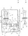
图1作为处理有价票券的设备的例子表示一个钞票分选设备1,它有一个按本发明第一种优选的实施形式的检验设备。FIG. 1 shows, as an example of a device for processing notes of value, a banknote sorting device 1 having a checking device according to a first preferred embodiment of the invention.
钞票分选设备1在外壳2内有一个钞票BN进口3,要处理的成捆钞票BN可以或手动或自动地,必要时在事先除去捆带后输入进口中,然后在那里堆成垛。输入进口3中的钞票BN通过分离机4从堆垛中逐张抽出,并借助限定传送路径的传送装置5通过一个用于检验钞票的传感器装置6传送。在此实施例中,传感器装置6有多个安装在一个公共外壳内的传感器模块。这些传感器模块在这里用于检验被检验钞票BN的真实性、状态及票面价值。在通过传感器装置6后,被检验的钞票BN根据传感器装置6的检查或检验结果以及规定的分选准则,经由可以分别通过转辙信号在两个不同位置间往复调整的转辙器7和相关的螺旋式分类堆垛机8,分类输出到出口9内,它们从那里可以或手动取出,或自动送出。钞票分选设备1的控制,尤其将传感器装置6的检验信号转换为用于转辙器的转辙器调整信号,在这里借助控制器10实现。The banknote sorting device 1 has a
如已提及的那样,在本实施例中传感器装置6有不同的传感器模块,其中在图中仅示出了要在下面详细介绍的传感器模块11,亦即按本发明优选的实施例用于检验有价票券,例如钞票BN的设备,下文称为检验设备。用于识别钞票BN的状态,亦即可周转性,和票面价值或币值的传感器模块是普通的、专业人员已知的传感器模块,因此不需要详细介绍。As already mentioned, in the present embodiment the
检验设备11在本实施例中设计用于探测和分析发光射线,它是在规定的钞票用规定波长的光线,例如在光谱的红外线区域内的光线照明时激励的。In the exemplary embodiment, the
检验设备11有一个传感器外壳12,该外壳包括一块对一束用于检验的光线透明的玻璃13,它封闭一个通往检测区14的窗口,在检验期间钞票BN至少部分处于此检测区内。传感器外壳12和玻璃13设计并尤其封闭为,使得不破坏传感器外壳12和/或玻璃13就不能未经许可地抓取包含在其内部的部件。The
此外通过检验设备11光学构件的配置和特性限定的检测区14,在与传感器外壳12的对置侧以原则上可选择的板33为界,从而钞票BN可借助图2中未表示的传送装置5沿图2中与图纸平面正交地延伸的方向T传送经过玻璃13旁。In addition, the
检验设备11有一个照明装置15用于向检测区14内以及尤其在至少部分处于此检测区14内的有价票券,例如钞票BN上输入照明射线,以及有一个光谱装置16用于检验并尤其光谱分辨地探测从检测区14或从在检测区内的有价票券出发的光线。在本例中,探测射线包括在由有价票券的种类规定的波长范围内的发光射线,例如红外线发光射线。从检测区14朝玻璃13方向出发的光线在下文中也称为探测射线。探测镜片17用于将从检测区14通过玻璃13进入传感器外壳12的光线,亦即探测射线,耦合在光谱装置16内。The
照明装置15有一个形式上为半导体激光器的半导体射线源18,在本例中它输出在可见光区域内的光线,以及有一个照明镜片。在另一些实施例中,半导体激光器也可以设计用于输出在红外线区域内的射线。照明镜片在照明射线路径内有第一准直镜19,用于生成照明射线或由从半导体射线源18输出的光线组成的平行的照明射束20,还有一个二色性射束分离器21,它反射照明射线或照明射束20的射线,并使照明射线或照明射束20在本例中偏转90°到玻璃13上,以及有第一聚光镜22,它用于将照明射线通过同样构成部分照明镜片的玻璃13聚焦在检测区14中,尤其在检测区14内的有价票券BN中。The
探测镜片17,沿着从检测区14或在检测区内的有价票券BN到光谱装置16并延伸到它内部的探测射线路径,除玻璃13外还包括第一聚光镜22、射束分离器21、以及第二聚光镜23,第一聚光镜22将从检测区14内有价票券BN上一点出发的射线聚集成一个平行的射束,射束分离器21对于要输入光谱装置16的射线是透明的,但作为散射的射线进入探测射线路径内的照明射线,则通过反射从探测射线路径滤除,而第二聚光镜23用于将平行的探测射束聚焦在光谱装置16的进口上。在第二聚光镜23与光谱装置16之间可选择设置滤波器24,用于从探测射线路径尤其在照明射线波长范围内滤除不希望的光谱成分,以及设置转向元件25,在本例中为反射镜,用于使探测射线偏转规定的角度,在本例中为90°。在另一些实施例中,滤波器24可以设在第二聚光镜23前的平行射线路径内。这样做的优点是,例如可以简单地使用干涉滤波器。The
光谱装置16有入射光阑26,该入射光阑包括一个在本实施例中呈缝隙状的光阑孔径27,其长度至少近似垂直于由探测射线路径确定的平面延伸。The
经光阑孔径27进入的探测射线,借助一个在本例中光谱装置16消色差的准直和聚焦镜28聚束。准直和聚焦镜28在图中只象征地表示为一个透镜,但在实际上往往设计为一些透镜的组合。消色差的光学镜指的是,该光学镜在光谱装置16所工作的波长范围内进行了色差校正。在另一些波长范围内相应的修正是不必要的。入射光阑26和准直和聚焦镜28配置为,使光阑孔径27至少非常接近地处于准直和聚焦镜28入射光阑侧的焦面点内。The probe radiation entering through the
光谱装置16还有一个空间分光装置29,在本例中为光栅,它使射入的探测射线,亦即来自检测区的光线,至少部分分解为光谱分离地、根据波长沿不同方向传播的光谱成分。The
光谱装置16的探测装置30用于沿至少一个空间方向空间分辨地探测光谱成分。在探测时生成的探测信号供给光谱装置16的评估装置31,它检测探测信号,并以此探测信号为基础实施将所检测的光谱与规定的光谱作比较。评估装置31与控制器10连接,以便将比较结果借助相应的信号传输给控制器10。The
在本例中,空间分光装置29是一个有线性结构的反射光栅,它的线平行于一个通过光阑孔径27纵向和准直和聚焦镜28光轴的平面延伸。线的距离选择为,使探测射线可以在规定的光谱区,在本例中为红外线区域内被分解成光谱。分光装置29为此定向为,使分离的光谱成分,在本例中为第一衍射级,通过准直和聚焦镜28聚焦在探测装置30上。为得到尽可能好的信噪比,分光装置29线的距离和位置选择为,使探测射线未光谱分解的部分,在本例中为零级衍射射线,不射入准直和聚焦镜28内,而是射在图中未表示的一个射线收集器上,例如一块用于吸收探测射线的板。In the present example, the
探测装置30有用于光谱成分的探测元件32的一种行式布局,例如一行CCD元件,它们至少近似平行于光谱成分的空间分解方向定向,亦即在这里平行于由光谱成分展开的面S,在这种情况下更准确地说是一个平面。在图3中用虚线示意表示平面S。The
为获得尽可能紧凑的结构,一方面使分光装置29沿两个方向相对于探测装置30以及在准直和聚集镜与促使射线路径折叠的反射构件(在这里是分光装置29)之间射入的探测射线的方向倾斜。因为在本实施例中,在准直和聚集镜28与反射构件,亦即分光装置29之间的探测射线的方向平行于准直和聚集镜28的光轴O延伸,所以首先,平的反射光栅29并因而还有它的线性结构,相对于准直和聚集镜28在探测射线路径的平面内的光轴O倾斜。因此,至少在分光装置29与准直和聚集镜28之间的区域内,由光谱成分生成的面S,在本例中是一个平面,相对于探测射线的方向或准直和聚集镜的光轴O倾斜角度β。尤其是,在探测射线路径的平面内的此平的反射光栅29的法线,相对于准直和聚集镜28的光轴O倾斜一个角度β(见图3)。第二,分光装置16,更准确地说镜面反射的入射垂线,亦即在这里是在反射光栅29线性结构平面上的法线,相对于探测射线的方向或准直和聚集镜28与分光装置29之间的光轴O倾斜一个角度α。In order to obtain a structure as compact as possible, on the one hand the
另一方面,探测装置30的探测元件32行至少近似地布置在一个包括光阑孔径27的平面内并沿一个垂直于通过光谱成分的传播方向确定的平面S与光阑孔径27相隔一定距离,在图3中处于光阑孔径27上方。在图2和3中为了视图清晰起见,入射光阑26和探测元件32的接收面表示为彼此隔开距离地平行于准直和聚集镜28的焦面,然而实际上在本例中它们基本上处于一个公共的平面内。沿平行于探测元件32行的方向看,光阑孔径27大体位于行的中心。On the other hand, the
由图2可以看出,由此还得出,在入射光阑26与准直和聚集镜28之间的区段内,也就是说,尤其也直接在准直和聚集镜28前,来自检测区14的探测射线在一个通过射在探测装置30上的光谱成分展开并构成边界的平面A上的几何投影,处于此在本例中是梯形的平面内。由此得到一种特别节省空间的配置。As can be seen from FIG. 2 , it also follows that in the section between the
在本实施例中,探测装置30、入射光阑26、准直和聚集镜28以及分光装置29设计并布置为,使它们处于一个圆柱形的空间区内,其圆柱体轴线通过准直和聚集镜28的光轴决定,以及它的圆柱体直径通过准直和聚集镜28的直径或透镜或其中最大透镜的直径决定。在这里,圆柱形空间区的长度优选地小于50mm,在本例中为40mm。由此使得分光装置29的空间需求特别小,与此同时可以达到一个与尺寸相比数值较大的口径。In this embodiment, the
为了在检测区14内光学检验有价票券,在这里是钞票BN,有价票券用照明射线,在本例中是用适用于激励发光射线的半导体射线源18的光线照明,以及从有价票券出发的光线,在这里是发光射线,通过探测镜片17和准直和聚集镜28形成一平行的探测射束。它至少部分分解为不同波长的光谱成分,它们根据波长沿不同的方向传播。在图2中,未被光谱分解的、被反射的零级衍射射线用一条实线表示,而由第一衍射级给定的两种不同波长的光谱成分用点线或虚线表示。这些光谱成分通过准直和聚集镜28聚焦在探测装置30上,更准确地说聚焦在包括探测元件32的行上,以及由它们空间分辨地探测。每个探测元件32配属一个传播方向,并因而根据波长配属一个光谱成分。因此评估装置31分别根据探测元件32的位置和由它们分别检测的色觉亮度构成一个光谱,然后可以将它与标准光谱作比较。In order to optically check a document of value in the
图4和5所示的第二种优选的实施形式,与第一种实施例的差别一方面在于分光装置的类型,另一方面在于照明装置的配置。因此,相同的构件采用同样的附图标记,以及针对第一种实施例的说明在这里也相应地适用。The second preferred embodiment shown in FIGS. 4 and 5 differs from the first embodiment on the one hand in the type of light splitting device and on the other hand in the configuration of the lighting device. The same components are therefore provided with the same reference numerals, and the description for the first exemplary embodiment also applies here correspondingly.
现在采用闪耀光栅29′取代平的反射光栅29,它的阶梯倾斜为,使第一衍射级朝镜面反射的方向进行。由此可以获得更高强度的光谱成分。Instead of the flat reflection grating 29, a blazed grating 29' is now used, the steps of which are inclined such that the first diffraction order proceeds in the direction of the specular reflection. Higher intensity spectral components can thus be obtained.
原则上在第一种实施例中照明装置可以绕第一聚光镜22的光轴旋转,不改变功能。为了能获得一种尽可能简单的结构形式,因此在本实施例中除准直和聚集镜28外,还设有半导体射线源18和准直管镜片19。In principle, in the first exemplary embodiment, the lighting device can be rotated about the optical axis of the
另一些实施例与第一和第二种实施例的区别在于,采用转向元件25′取代转向元件25,它代替入射光阑26。在图6和7中示出了第一种实施例的一种相应的修改。图中对于相同的元件采用与第一种实施例中同样的附图标记,以及在第一种实施例中对这些元件的说明在这里也适用。转向元件25′现在是一个在第一种实施例中光阑孔径27大小的反射镜,以及设置在准直和聚集镜28的焦面内。Other exemplary embodiments differ from the first and second exemplary embodiments in that, instead of the deflecting
再另一些优选的实施形式与上面已描述的那些实施形式的区别在于,探测装置30和入射光阑26组合。为此,光阑孔径设计在一块也同时安装了探测元件32的薄板内。Further preferred embodiments differ from those already described above in that
在另一些实施例中,照明装置15作为射线源有一个光敏二极管、超发光二极管或OLED,取代激光二极管18。In other exemplary embodiments, instead of the
在另一些实施例中,照明装置15还可以有至少两个半导体射线源,它们在不同的重点波长,亦即发射波长用发射强度加权的平均值时输出光线,以及可彼此独立地接通和断开。由此可以在不同的波长并列地进行检验。In some other embodiments, the illuminating
在另一些优选的实施例中,可以整个取消入射光阑26。此时照明装置15设计为,它在检测区只照明一个狭窄、细长的区域,为此第一聚光镜19可含有一个圆柱形透镜。In other preferred embodiments, the
再另一些实施例与上面已描述的那些实施形式的区别在于,在探测射线路径内还设置另一些透镜,以便通过探测镜片的元件和准直和聚集镜28减少成像缺陷或改善照明。Further exemplary embodiments differ from those already described above in that additional lenses are arranged in the path of the detection beam in order to reduce imaging defects or improve the illumination by means of elements of the detection optics and the collimating and focusing
另一些实施例与上面已描述的那些实施形式的区别在于,转向元件25或25′是一个射束分离器,所以探测射线穿过它射出的部分,可以例如为生成有价票券的图像而输出耦合。Other exemplary embodiments differ from those already described above in that the deflecting
在另一些实施例中也可以使用透射照明。Trans-illumination may also be used in other embodiments.
此外,并不一定需要使用反射的分光装置,例如反射光栅29。例如在另一种只是在这一方面与图6和7所示实施例不同的实施例中,可以在探测射线路径内在准直和聚集镜28之后设透射光栅29″,它将探测射线至少部分分解为一些光谱成分。然后这些光谱成分可以借助至少一个反射构件34,例如相对于通过光谱成分展开的平面倾斜的反射镜,反射到准直和聚集镜28内。Furthermore, it is not necessarily necessary to use reflective spectroscopic means, such as
通过射线路径在准直和聚集镜后折叠,获得比一种也可能的设备紧凑得多的结构形式,在这种也可能的设备中,在透射光栅后面设置聚集镜和探测装置来取代反射镜。By folding the ray paths after collimating and concentrating mirrors, a much more compact design is obtained than in a also possible device in which instead of mirrors a concentrating mirror and a detection device are arranged behind a transmission grating .
在另一些实施例中,传感器外壳12和/或板33也可以有不同的设计或整个取消。In other embodiments, the
此外,在另一些实施例中评估装置31也可以组合在控制器10内。In addition, in some other embodiments, the
另一些优选的实施形式与上面已描述的那些实施例的区别在于,取代探测装置,取代一行CCD元件,具有设排成行的光探测元件,例如CMOS元件,或具有用于探测在另一些波长范围内的光线的光探测元件。Other preferred embodiments differ from those described above in that, instead of the detection device, instead of a row of CCD elements, there are photodetection elements arranged in rows, such as CMOS elements, or for detecting light at other wavelengths. light detection element within the range of light.
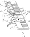
在图10至12中表示了这种检验设备的一种实施例,它如其他所有已介绍的检验设备一样可以例如使用于图1中处理有价票券的设备中。10 to 12 show an exemplary embodiment of such a verification device, which, like all other verification devices described, can be used, for example, in the device for processing notes of value in FIG. 1 .
检验设备11″除探测元件的类型外,与图1所示检验设备11的区别还在于,现在探测射线路径进入探测装置的两个边缘探测元件之间并到达分光装置上。尤其是这些检验设备的区别仅在于,探测装置30由探测装置34代替,转向元件25由光导体35代替,以及评估装置31由改型后的评估装置31′代替。此外,分光装置29的定向与探测装置30不同。因为本检验设备除此之外与第一种实施例的没有区别,所以相同的部分采用同样的附图标记,以及在说明第一种实施例时针对这些部分的设计也相应地适用于此。The
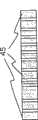
图12中详细表示的探测装置34现在有一个支架36,在本例中是一个陶瓷基层,在此陶瓷基层上的第一个行状配置39中设第一探测元件37,以及在第二个行状配置39′中设第二探测元件38。在本实施例中,探测元件37和38仅沿一条直线布置。在图12中,通过一个设计在支架上的放大级与探测元件电连接的触点接通元件40处于探测元件37和38下方,触点接通元件与连接评估电路或评估装置的信号连接装置连接。The
探测元件37和38处于支架36内一个槽或口41的对置侧,在本实施例中所述槽或口41设计为矩形。因此在两个边缘探测元件42与43之间存在一个空隙。The
探测元件37与探测元件38不同之处在于它们的光谱探测范围。
探测元件37涉及探测在可见光谱和红外线附近范围内的亦即直至波长1100nm的光线的探测元件。在本实施例中它们可用的光谱探测范围在400nm与1100nm之间。在这里例如可以采用硅基探测元件。The
探测元件38涉及探测在红外线范围内的光线的探测元件。在本实施例中它们可用的光谱探测范围在900nm与1700nm之间。在这里例如可以采用铟镓砷(InGaAs)基探测元件,它们在900nm以上的光谱区是灵敏的。The
探测元件37和38相对于分光装置29设置为,使波长超过900nm的光谱成分从分光装置导向探测元件38,以及波长在900nm以下的光谱成分从分光装置导向探测元件37。The
与CCD场相比,只需使用数量少得多的探测元件37和38,例如数量在10与30之间,但尽管如此它们有更大的探测面积以及缩小的非光敏区的一部分。在这里探测面积确定为,只检测射入此面积上的光线。Compared to a CCD field, only a much smaller number of
探测面优选地有至少0.1mm2的面积,在本例中它的高为2mm以及宽为1mm,其中在相邻探测元件之间的非光敏区约为50μm。The detection surface preferably has an area of at least 0.1 mm2 , in the present example it has a height of 2 mm and a width of 1 mm, wherein the non-photosensitive regions between adjacent detection elements are approximately 50 μm.
在本实施例中,探测元件37和38可逐个彼此独立和尤其平行地读出。In the present exemplary embodiment,
此外,在本实施例中已提及的每个探测元件的放大级还含有一个模/数转换器,它将各自探测元件的模拟信号转换为数字探测信号,该数字探测信号描述射在探测面上的射线强度。In addition, the amplification stage of each detection element mentioned in this embodiment also contains an analog/digital converter, which converts the analog signal of the respective detection element into a digital detection signal, which describes the ray intensity on .
在探测射线路径内,设由适用的透明材料制的光导体35,它至少在可被检验设备探测到的光谱范围内的导引进入它内部的探测射线,并朝分光装置29的方向偏转。In the detection beam path, a
光导体35的一个探测射线通过它从光导体射出的端部44,设在口41内并因而设在准直和聚集镜28的焦面点内。因此探测射线路径穿过两个边缘探测元件42和43之间延伸。在这里,光导体35的射出面或端部44构成光谱装置的入射光阑或进口缝隙。An
光导体35相对于准直和聚集镜28的光轴O定向,使通过端部44输出的射线,居中地经由射束横截面,至少近似平行于光轴O以及垂直于支架36表面和尤其探测元件的行状布置延伸。The
由图11可以看出,分光装置29,尤其它的光栅线,在图11中表示的平面内与光轴O垂直定向。相反地,在图10所示与图11中的平面正交的平面内,由光栅线给定的线性结构则相对于光轴O倾斜。It can be seen from FIG. 11 that the
因此,通过分光装置29产生的光谱成分借助准直和聚集镜28聚焦在探测装置34上,更准确地说聚焦在探测元件37和38上,探测元件因此探测相应的光谱成分。The spectral components generated by the
通过选择由光导体35、准直和聚集镜28、分光装置29以及探测装置34构成的这种配置,可以达到使探测射线路径平行地或至少在由借助分光装置29生成的光谱成分确定的平面中延伸。By selecting this configuration consisting of the
在这里角度α选择为,根据规定波长,在本例中规定波长是通过使用发光测量规定的发光的激励波长,将光谱成分聚焦在两个边缘探测元件42与43之间的空隙中并因而不被探测到。Here the angle α is chosen such that, depending on the specified wavelength, in this case the excitation wavelength of the specified luminescence by using the luminescence measurement, the spectral components are focused in the gap between the two
作为一种可选方案,评估装置31′与评估装置31相比作如下修改:基本上可以平行检测探测元件或探测装置的探测信号。在这里基本上平行的意思是,探测信号就它们的时间位置而言可以有至少如此程度的差异,这种差异如同例如借助一种多路复用法通过一条总线向评估装置31′传输时所必要的那样。As an alternative, the
此外,评估装置31′设计为,向着半导体射线源18的脉冲输出信号方向,在一个根据预期的发光给定的时刻后,检测探测装置34的探测信号。Furthermore, the
探测元件37和38由此可以平行读出,因而可以实现短的集成时间和尤其高的测量重复频率。所述措施同样有利于提高信噪比。
这种检验设备尤其可以使用于实施所谓的“单次(single-shot)”测量,此时仅向一个照明或激励脉冲方向实施发光射线光谱持性的单一测量,它有足够的评估精度。Such a test device can be used in particular to carry out so-called "single-shot" measurements, in which case a single measurement of the spectral persistence of the luminescence radiation is carried out in the direction of only one illumination or excitation pulse, which is sufficiently accurate for evaluation.
此外,评估装置31′可按选择设计为,使得还可以将检验设备使用于,在通过半导体射线源输出激励脉冲后,按时间顺序多次检测探测元件的探测信号并因而检测多个光谱,以及由此评估光谱随时间的发展。Furthermore, the evaluation device 31' can optionally be designed in such a way that the test device can also be used to detect the detection signal of the detection element and thus a plurality of spectra several times in chronological order after the output of the excitation pulse by the semiconductor radiation source, and The evolution of the spectrum over time is thus assessed.
按图13的另一种实施形式,与上述图10至12所示实施例的区别仅在于,准直和聚集镜28和形式上为平的反射光栅的分光装置29用一个成像的分光元件45代替,以承担它们的功能。其他所有的构件和部分不变,所以对它们使用相同的附图标记,以及针对上述实施例的详细说明也适用于此。According to another embodiment of FIG. 13 , the difference from the above-mentioned embodiment shown in FIGS. 10 to 12 is only that the collimating and concentrating
现在采用全息光栅45作为成像的分光元件,它光谱分辨地将入射光阑44,在本例中是光导体35的端部44,在探测元件37或38上成像。A
成像光栅45在本例中优选地每mm有大约300条以上,特别优选地大约500条以上的条纹或线,亦即衍射元素,为的是尽管结构紧凑但仍能足够地分散在探测元件21上的发光射线。在这里,成像光栅45与探测装置34之间的距离优选地小于约70mm,特别优选地小于约50mm。In this example, the imaging grating 45 preferably has more than about 300, particularly preferably more than about 500, fringes or lines per mm, i.e. diffractive elements, in order to be sufficiently dispersed in the
在另一些实施例中还可以规定,各个探测元件45尤其沿光谱成分的分散方向有不同的尺寸,如图14中举例所示。因为通常并不是评估光谱的所有波长或仅仅评估相同宽度的波长区,而是有目的地只评估个别波长或不同宽度的波长区,所以探测元件的宽度可以设计为与各自要评估的波长(区)相匹配地平行于由光谱成分确定的平面。In other exemplary embodiments it can also be provided that the
按再另一种实施例,尤其是其中使用一个准直和聚焦镜的实施例,可以在探测装置或一行探测元件前设圆柱形透镜,探测射线聚焦在探测元件上,为此它的圆柱体轴线平行于所述的行定向。According to yet another embodiment, especially one in which a collimating and focusing mirror is used, a cylindrical lens can be arranged in front of the detection device or a row of detection elements, and the detection rays are focused on the detection elements, for which reason its cylinder The axes are oriented parallel to said rows.
借助这种圆柱形透镜,可以增大检测区沿一个与圆柱形透镜的圆柱体轴线正交的方向相对应的方向使用于探测的区段,并因而提高可供探测使用的强度。By means of such a cylindrical lens, it is possible to increase the section of the detection zone available for detection in a direction corresponding to a direction perpendicular to the cylinder axis of the cylindrical lens and thus increase the intensity available for detection.
Claims (27)
Translated fromChineseApplications Claiming Priority (5)
| Application Number | Priority Date | Filing Date | Title |
|---|---|---|---|
| DE102006017256ADE102006017256A1 (en) | 2006-04-12 | 2006-04-12 | Optical examination device for value documents, has coverage area, spectrographic equipment, detection device terminating in spatial direction for detecting spectral components |
| DE102006017256.6 | 2006-04-12 | ||
| DE102006045624.6 | 2006-09-27 | ||
| DE102006045624ADE102006045624A1 (en) | 2006-09-27 | 2006-09-27 | Device for optically examining security documents, has detection region, in which a security document is located during the examination, and spectrographic device, and device has spatially dispersing optical device |
| PCT/EP2007/003220WO2007118655A1 (en) | 2006-04-12 | 2007-04-11 | Apparatus and method for optically examining security documents |
Publications (2)
| Publication Number | Publication Date |
|---|---|
| CN101467182Atrue CN101467182A (en) | 2009-06-24 |
| CN101467182B CN101467182B (en) | 2012-03-28 |
Family
ID=38514547
Family Applications (1)
| Application Number | Title | Priority Date | Filing Date |
|---|---|---|---|
| CN2007800214140AActiveCN101467182B (en) | 2006-04-12 | 2007-04-11 | Device and method for optical checking of documents of value |
Country Status (3)
| Country | Link |
|---|---|
| CN (1) | CN101467182B (en) |
| DE (1) | DE102006017256A1 (en) |
| ZA (1) | ZA200808483B (en) |
Cited By (2)
| Publication number | Priority date | Publication date | Assignee | Title |
|---|---|---|---|---|
| CN102262796A (en)* | 2010-05-25 | 2011-11-30 | 旭精工株式会社 | Coin sorting device |
| CN103765483A (en)* | 2011-08-25 | 2014-04-30 | 光荣株式会社 | Paper item identification device, paper item spectrometry light guide and light guide case |
Families Citing this family (5)
| Publication number | Priority date | Publication date | Assignee | Title |
|---|---|---|---|---|
| DE102008028689A1 (en) | 2008-06-17 | 2009-12-24 | Giesecke & Devrient Gmbh | Sensor device for the spectrally resolved detection of value documents and a method relating to them |
| DE102008028690A1 (en) | 2008-06-17 | 2009-12-24 | Giesecke & Devrient Gmbh | Sensor device for the spectrally resolved detection of value documents and a method relating to them |
| DE102009025368A1 (en) | 2009-06-18 | 2010-12-23 | Giesecke & Devrient Gmbh | Optical system and sensor for testing value documents with such an optical system |
| DE102010051087A1 (en)* | 2010-11-12 | 2012-05-16 | Beb Industrie-Elektronik Ag | Method and device for checking the authenticity of banknotes with security windows |
| DE102016111354A1 (en)* | 2016-06-21 | 2017-12-21 | Bundesdruckerei Gmbh | AUTHENTICATION DOCUMENT |
Family Cites Families (6)
| Publication number | Priority date | Publication date | Assignee | Title |
|---|---|---|---|---|
| US4146792A (en)* | 1973-04-30 | 1979-03-27 | G.A.O. Gesellschaft Fur Automation Und Organisation Mbh | Paper secured against forgery and device for checking the authenticity of such papers |
| US5574790A (en)* | 1993-09-27 | 1996-11-12 | Angstrom Technologies, Inc. | Fluorescence authentication reader with coaxial optics |
| US6621916B1 (en)* | 1999-09-02 | 2003-09-16 | West Virginia University | Method and apparatus for determining document authenticity |
| EP1344193B1 (en)* | 2000-12-21 | 2007-07-04 | De La Rue International Limited | Optical sensor device and method for spectral analysis |
| DE10127836A1 (en)* | 2001-06-08 | 2003-01-30 | Giesecke & Devrient Gmbh | Device for examining documents |
| DE102004035494A1 (en)* | 2004-07-22 | 2006-02-09 | Giesecke & Devrient Gmbh | Device and method for checking value documents |
- 2006
- 2006-04-12DEDE102006017256Apatent/DE102006017256A1/ennot_activeWithdrawn
- 2007
- 2007-04-11CNCN2007800214140Apatent/CN101467182B/enactiveActive
- 2008
- 2008-10-06ZAZA200808483Apatent/ZA200808483B/enunknown
Cited By (4)
| Publication number | Priority date | Publication date | Assignee | Title |
|---|---|---|---|---|
| CN102262796A (en)* | 2010-05-25 | 2011-11-30 | 旭精工株式会社 | Coin sorting device |
| CN102262796B (en)* | 2010-05-25 | 2013-09-18 | 旭精工株式会社 | Coin sorting device |
| CN103765483A (en)* | 2011-08-25 | 2014-04-30 | 光荣株式会社 | Paper item identification device, paper item spectrometry light guide and light guide case |
| CN103765483B (en)* | 2011-08-25 | 2016-02-10 | 光荣株式会社 | paper identification device |
Also Published As
| Publication number | Publication date |
|---|---|
| CN101467182B (en) | 2012-03-28 |
| ZA200808483B (en) | 2009-10-28 |
| DE102006017256A1 (en) | 2007-10-18 |
Similar Documents
| Publication | Publication Date | Title |
|---|---|---|
| CN102169607B (en) | Device for verifying value documents | |
| KR101353752B1 (en) | Apparatus and method for optically examining security documents | |
| US8598558B2 (en) | Sensor device for the spectrally resolved capture of valuable documents and a corresponding method | |
| US8817242B2 (en) | Sensor device for the spectrally resolved capture of valuable documents and a corresponding method | |
| CN101467182A (en) | Device and method for optically checking value documents | |
| EP4067879A1 (en) | Identification apparatus | |
| US9460579B2 (en) | Sensor for checking value documents | |
| AU2012203003B2 (en) | Device and method for verifying value documents | |
| HK1158799B (en) | Sensor device for the spectrally resolved capture of valuable documents and a corresponding method | |
| HK1158798B (en) | Sensor device for the spectrally resolved capture of valuable documents and a corresponding method | |
| HK1158798A (en) | Sensor device for the spectrally resolved capture of valuable documents and a corresponding method |
Legal Events
| Date | Code | Title | Description |
|---|---|---|---|
| C06 | Publication | ||
| PB01 | Publication | ||
| C10 | Entry into substantive examination | ||
| SE01 | Entry into force of request for substantive examination | ||
| C14 | Grant of patent or utility model | ||
| GR01 | Patent grant | ||
| TR01 | Transfer of patent right | Effective date of registration:20180309 Address after:Munich, Germany Patentee after:Jiejia German currency Technology Co., Ltd. Address before:Munich, Germany Patentee before:Giesecke & Devrient GmbH | |
| TR01 | Transfer of patent right |