CN101466330B - Frames for hyperextension braces - Google Patents
Frames for hyperextension bracesDownload PDFInfo
- Publication number
- CN101466330B CN101466330BCN2007800220264ACN200780022026ACN101466330BCN 101466330 BCN101466330 BCN 101466330BCN 2007800220264 ACN2007800220264 ACN 2007800220264ACN 200780022026 ACN200780022026 ACN 200780022026ACN 101466330 BCN101466330 BCN 101466330B
- Authority
- CN
- China
- Prior art keywords
- frame
- support
- hyperextension
- side members
- brace according
- Prior art date
- Legal status (The legal status is an assumption and is not a legal conclusion. Google has not performed a legal analysis and makes no representation as to the accuracy of the status listed.)
- Expired - Fee Related
Links
Images


Classifications
- A—HUMAN NECESSITIES
- A61—MEDICAL OR VETERINARY SCIENCE; HYGIENE
- A61F—FILTERS IMPLANTABLE INTO BLOOD VESSELS; PROSTHESES; DEVICES PROVIDING PATENCY TO, OR PREVENTING COLLAPSING OF, TUBULAR STRUCTURES OF THE BODY, e.g. STENTS; ORTHOPAEDIC, NURSING OR CONTRACEPTIVE DEVICES; FOMENTATION; TREATMENT OR PROTECTION OF EYES OR EARS; BANDAGES, DRESSINGS OR ABSORBENT PADS; FIRST-AID KITS
- A61F5/00—Orthopaedic methods or devices for non-surgical treatment of bones or joints; Nursing devices ; Anti-rape devices
- A61F5/01—Orthopaedic devices, e.g. long-term immobilising or pressure directing devices for treating broken or deformed bones such as splints, casts or braces
- A61F5/02—Orthopaedic corsets
- A61F5/024—Orthopaedic corsets having pressure pads connected in a frame for reduction or correction of the curvature of the spine
Landscapes
- Health & Medical Sciences (AREA)
- Nursing (AREA)
- Orthopedic Medicine & Surgery (AREA)
- Engineering & Computer Science (AREA)
- Biomedical Technology (AREA)
- Heart & Thoracic Surgery (AREA)
- Vascular Medicine (AREA)
- Life Sciences & Earth Sciences (AREA)
- Animal Behavior & Ethology (AREA)
- General Health & Medical Sciences (AREA)
- Public Health (AREA)
- Veterinary Medicine (AREA)
- Orthopedics, Nursing, And Contraception (AREA)
- Rehabilitation Tools (AREA)
- Prostheses (AREA)
- Mutual Connection Of Rods And Tubes (AREA)
Abstract
Description
Translated fromChinese技术领域technical field
本发明涉及一种具有框架结构的过伸型支具,该框架结构具有可调的上部和下部支撑部以及可调的侧部构件。可以在不需要任何工具的情况下进行所有的调节。优选地,所述框架由复合材料制成。The present invention relates to a hyperextension brace having a frame structure with adjustable upper and lower supports and adjustable side members. All adjustments can be made without any tools. Preferably, the frame is made of composite material.
背景技术Background technique
例如从US 3,220,407和US 6,010,472可以看到的,过伸型支具是以前公知的装置。过伸型支具通常使用三点杠杆系统,其中该支具包括与胸骨或锁骨下(sub-clavicula)区域以及骨盆和耻骨身体区域接合的支撑部以及在腰部和下胸区域内与背部接合的支撑部。在处理椎骨问题例如压缩性骨折方面已经证明所述装置是有效的。Hyperextension braces are previously known devices as can be seen, for example, from US 3,220,407 and US 6,010,472. Hyperextension braces typically use a three-point lever system in which the brace includes supports that engage the sternal or sub-clavicula region and the pelvic and pubic body region, and braces that engage the back in the lumbar and lower chest regions. support section. The device has proven effective in treating vertebral problems such as compression fractures.
即使现有技术的过伸型支具原则上都是有效的,仍然可在某些方面对它们进行改进。例如,支具的不同构件之间的连接件经常包括螺钉和螺栓,这需要用工具来调节支具的尺寸。通常它们由金属部件制成,其不仅沉重而且会干扰X光设备。Even though the hyperextension braces of the prior art are effective in principle, they can still be improved in certain respects. For example, the connections between the different components of the brace often include screws and bolts, which require tools to adjust the size of the brace. Usually they are made of metal parts which are not only heavy but also interfere with X-ray equipment.
EP0319224公开了一种腰部牵引设备,该设备包括通过棒相互连接的上部和下部支撑部,所述棒在上部和下部支撑部之间延伸并穿过壳体,每个壳体具有由杆操作的用于调节棒的长度的机构。牵引控制组件设置成用于在设备与患者进行的治疗过程相连时测量所施加的力。该设备通过吊带固定到患者上。EP0319224 discloses a lumbar traction device comprising upper and lower supports interconnected by rods extending between the upper and lower supports and through housings, each housing having a lever operated Mechanism for adjusting the length of the rod. The traction control assembly is configured to measure the force applied while the device is coupled to a patient undergoing a treatment procedure. The device is secured to the patient by straps.
本发明的目的是提供一种无需使用任何工具就能容易地装配在患者上的过伸型支具。另一个目的是提供一种不会与X光设备干涉的过伸型支具。It is an object of the present invention to provide a hyperextension brace that can be easily fitted on a patient without using any tools. Another object is to provide a hyperextension brace that does not interfere with X-ray equipment.
发明内容Contents of the invention
本发明提供一种用于过伸型支具的框架,其包括:由侧部构件连接的锁骨下支撑部以及骨盆和耻骨支撑部。The present invention provides a frame for a hyperextension brace comprising: a subclavian support and a pelvic and pubic support connected by side members.
根据本发明,侧部构件的高度能够通过非旋转伸缩式的可锁定的连接件进行调节。According to the invention, the height of the side members can be adjusted by means of non-rotating telescoping lockable connections.
优选地,上部锁骨下支撑部通过调整螺丝(turnbuckle screw)装置连接到侧部构件。Preferably, the upper subclavian support is connected to the side members by a turnbuckle screw arrangement.
所述框架可由复合材料制成,合适地为玻璃纤维和/或碳纤维增强的聚合物。The frame may be made of composite material, suitably a glass fiber and/or carbon fiber reinforced polymer.
本发明由权利要求1限定,而实施例在从属权利要求中列出。The invention is defined by
附图说明Description of drawings
下面将参照附图详细描述本发明,其中:The present invention will be described in detail below with reference to the accompanying drawings, wherein:
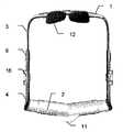
图1是支具的主框架的前视图;Fig. 1 is the front view of the main frame of brace;
图2是从主框架的前面看到的立体图;Fig. 2 is a perspective view seen from the front of the main frame;
图3是主框架的侧视图;Fig. 3 is a side view of the main frame;
图4是主框架的后视图;Fig. 4 is the back view of main frame;
图5是处于闭合位置的锁定装置的立体剖面图;Figure 5 is a perspective sectional view of the locking device in a closed position;
图6是处于打开位置的锁定装置的立体剖面图;Figure 6 is a perspective sectional view of the locking device in an open position;
图7是示出衬垫和螺纹的上部支撑部的透视图;Figure 7 is a perspective view of the upper support showing the gasket and threads;
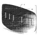
图8是背部衬垫的立体图;Figure 8 is a perspective view of the back pad;
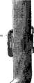
图9是锁扣的外部立体图;以及Figure 9 is an external perspective view of the lock; and
图10是锁扣的内部立体图。Fig. 10 is an internal perspective view of the buckle.
具体实施方式Detailed ways
根据本发明的过伸型支具框架的一个实施例在附图中示出。该支具基本上包括如图1-4所示的主框架和具有图8所示的背部衬垫的背带。从现有技术可知使用所述支具来治疗患者的工作原理。One embodiment of a hyperextension brace frame according to the invention is shown in the accompanying drawings. The brace basically comprises a main frame as shown in FIGS. 1-4 and a harness with a back pad as shown in FIG. 8 . The principle of operation of treating patients with such braces is known from the prior art.
主框架包括带有衬垫12的上部锁骨下支撑部1,所述衬垫12设置成在患者的胸骨或锁骨下区域上施加压力。上部支撑部1通过上部和下部侧部构件3、4连接到下部骨盆和耻骨支撑部2,该支撑部2设置成在患者的骨盆和耻骨区域上施加压力。The main frame comprises an upper
从图2和图3中可以看到,侧部构件3、4在其端部向前突出,使得上部支撑部1和下部支撑部2位于侧部构件3、4的前方。上部支撑部1和下部支撑部2均轻微弯曲或成椭圆形以便舒适地安装在患者上。As can be seen in FIGS. 2 and 3 , the
参照图5和图6,下部耻骨支撑部2通过设置在每一侧的锁定装置7连接到下部耻骨侧部构件4。侧部构件4具有一体的侧面部分以便与下部支撑部2相连。侧部构件4可相对于下部支撑部2滑动并可锁定在多个位置。优选地,为了结构稳定性,侧部构件4或多或少地被支撑部2包围,就像阴/阳或伸缩连接。外部元件或阳元件应当至少与内部元件或阴元件的边缘或其它导向部分接合,以便内部元件或阴元件在滑动时由外部元件或阳元件引导,在锁定时被牢固地保持在适当位置而不能平移和旋转。在图5和图6中,外部元件或阳元件完全包围内部元件或阴元件,但是外部元件或阳元件可在一侧开口,使得外部元件或阳元件以C形状包围内部元件或阴元件。在此说明书中,具有这种功能的连接件被称为非旋转伸缩式连接件,不论是否完全包围。Referring to Figures 5 and 6, the lower
上部和下部侧部构件3、4也通过类似的锁定装置6联接在一起。锁定装置6可以是与锁定装置7相同的设计。The upper and
在图5和图6中示出了锁定装置的一个实施例。该锁定装置包括连接片8,该连接片8可枢转地附装到被连接的元件之一,例如下部支撑部2和侧部构件3的下部元件4。连接片的下侧设有齿9,该齿可与设置在另一个被连接的元件内的凹部10相接合。可通过如图6所示提起连接片8、将所述元件相对于彼此延伸或回缩、然后如图5所示将连接片8推下,来调节所述框架在下部支撑部2处的宽度和侧部构件3、4的高度。An embodiment of a locking device is shown in FIGS. 5 and 6 . The locking means comprise a connecting
锁定销18可分别插入被连接的元件和连接片元件8的孔19A、19B中,以将连接片固定在锁定位置。
还如图5和6所示,框架的元件优选地在横向方向弯曲以改进抗弯性。As also shown in Figures 5 and 6, the elements of the frame are preferably bent in the transverse direction to improve bending resistance.
在附图中,下部骨盆和耻骨支撑部具有联合(symphysis)衬垫11。为了最好地进行支撑,下部骨盆和耻骨支撑部应当刚好定位在腹股沟线的上方(上部)。这样,联合衬垫11应当覆盖耻骨坐骨(pubis ischiadicum)(=联合)。优选地,下部支撑部构件以两种方式设置,一种是具有联合衬垫11,一种没有联合衬垫11。从上述讨论可以理解,如果需要的话,很容易释放整个下部耻骨支撑部2并在所述两种设置方式之间改变。In the figures, the lower pelvis and pubic support have a
原则上,可以为上部锁骨下支撑部1设置相同类型的滑动的且可锁定的锁定装置。但是,在图7中示出用于上部支撑部的滑动的且可锁定的锁定装置的一个优选的实施例。锁骨下支撑部1包括设置在略微成角度的支撑部1的相对端的两个锁骨下衬垫12。所述支撑部带有内螺纹13以便与设置在与侧部构件3成一体的水平部分15上的外螺纹14共同作用。所述螺纹具有相对的节距,从而上部支撑部1可作为调整螺丝而延伸和回缩。如果支撑部1沿一个方向——合适地为朝向身体——旋转,则侧部构件被拉在一起,并且如果支撑部1沿另一方向——远离身体——旋转,则侧部构件3被分离。In principle, the same type of sliding and lockable locking means could be provided for the upper
由于支撑部1略微成角度,所以旋转支撑部1导致侧部构件弯曲,这会引起阻力。锁骨下支撑部和侧部构件3的角度选择成使得具有平衡位置,即附图中所示位置。此位置对应于对患者来说通常很舒适的位置,其中衬垫基本上平靠在患者身体上。但是,仅需要很小的力以使锁骨下支撑部1围绕平衡位置旋转一个小的角度。这将导致衬垫在患者的身体上围绕衬垫12停靠的锁骨(claviculae)和肋骨架将自身调节为小的变型。为了最好地进行支撑,锁骨下衬垫12应当定位在锁骨以下大约2cm处。Since the
为了调节上部支撑部1的宽度,需要在任一方向上进行一次或多次整圈转动(360°)。侧部构件的阻力并不是很大,能够容易地手动完成。螺纹13、14的节距选择成使得一次转动产生大约7mm的延伸或回缩。当衬垫12停靠在患者身体上时,就锁定上部支撑部1的宽度。In order to adjust the width of the
图8示出背部衬垫5。为清晰起见省略了背带以便不妨碍观察。背部衬垫5总体为卵形以便舒适地放置在患者的腰部和下胸区域。背带穿过背部衬垫5中的孔20,并在与下部支撑部2相距一段距离处附装到侧部构件3。面对患者背部的内侧基本光滑。FIG. 8 shows the
图9示出用于拉紧和可释放地紧固腰带的锁扣16。优选地,处于对称的原因在每一侧都有一个锁扣,以便更易于使背部衬垫5在身体上定中心。每个锁扣16具有杠杆机构17,其可在锁扣被紧固时吸收所述带的一定量的松弛。杠杆机构17可枢转地附装在一侧并可在另一侧关闭和打开。合适地,杠杆机构17的长度约为50mm,以便每个锁扣吸收大约100mm的松弛。背带的长度可通过常规装置(未示出)在背部衬垫5或锁扣处进行调节。Figure 9 shows the
如图10所示,与侧部构件的连接位置优选地在高度上可调。凹部21设置在下部侧部构件4中。每个锁扣16具有弹性舌部22,该舌部能够可释放地卡入凹部21以将锁扣在合适的高度处锁定就位。As shown in Figure 10, the connection position to the side members is preferably adjustable in height. The recess 21 is provided in the
优选地,整个支具由非金属的、非磁性的和轻质的材料制成。例如,主框架可由玻璃纤维和/或碳纤维增强的聚合物制成。这些部件可注塑模制而成。锁扣16也由塑料制成,背带由合成或天然纤维制成。Preferably, the entire brace is made of non-metallic, non-magnetic and lightweight material. For example, the main frame may be made of glass fiber and/or carbon fiber reinforced polymer. These parts may be injection molded. The
本发明提供了一种便利的、经济的并且可不用任何工具进行装配的过伸型支具。由于材料的选择,所述支具重量轻、易于清洁且不会干扰对电或磁干扰敏感的设备。所述材料可以是热塑性的,使得可以通过加热元件和调适形状而进行调节。框架的形状可在很宽的范围内进行调节,并且可在侧部以及在上部和下部支撑部处独立地进行调节,这使得一种尺寸就足以覆盖患者尺寸的全部范围。The present invention provides a hyperextension brace that is convenient, economical and can be assembled without any tools. Due to the choice of materials, the brace is lightweight, easy to clean and does not interfere with equipment sensitive to electrical or magnetic disturbances. The material may be thermoplastic so that it can be adjusted by heating elements and adapting the shape. The shape of the frame is adjustable over a wide range and is independently adjustable at the sides and at the upper and lower supports, making one size sufficient to cover the full range of patient sizes.
在说明书和附图中,已经作为本发明的实施例详细示出了具体实施方式。本发明的范围仅由下面的权利要求限定。In the specification and drawings, specific embodiments have been shown in detail as examples of the present invention. The scope of the invention is limited only by the following claims.
Claims (11)
Translated fromChineseApplications Claiming Priority (3)
| Application Number | Priority Date | Filing Date | Title |
|---|---|---|---|
| EP06115288AEP1867308B1 (en) | 2006-06-12 | 2006-06-12 | Frame for a hyperextension brace |
| EP06115288.0 | 2006-06-12 | ||
| PCT/EP2007/055725WO2007144328A1 (en) | 2006-06-12 | 2007-06-11 | Frame for a hyperextension brace |
Publications (2)
| Publication Number | Publication Date |
|---|---|
| CN101466330A CN101466330A (en) | 2009-06-24 |
| CN101466330Btrue CN101466330B (en) | 2011-10-12 |
Family
ID=37081657
Family Applications (1)
| Application Number | Title | Priority Date | Filing Date |
|---|---|---|---|
| CN2007800220264AExpired - Fee RelatedCN101466330B (en) | 2006-06-12 | 2007-06-11 | Frames for hyperextension braces |
Country Status (8)
| Country | Link |
|---|---|
| US (1) | US8262598B2 (en) |
| EP (2) | EP1867308B1 (en) |
| JP (1) | JP2009539519A (en) |
| CN (1) | CN101466330B (en) |
| AT (2) | ATE485019T1 (en) |
| DE (2) | DE602006017669D1 (en) |
| ES (2) | ES2353529T3 (en) |
| WO (1) | WO2007144328A1 (en) |
Families Citing this family (8)
| Publication number | Priority date | Publication date | Assignee | Title |
|---|---|---|---|---|
| GB2456183A (en) | 2008-01-04 | 2009-07-08 | Gw Pharma Ltd | Anti-psychotic composition comprising cannabinoids and anti-psychotic medicament |
| ITTV20100015A1 (en)* | 2010-02-17 | 2011-08-18 | Corrado Menegazzo | AN IMPROVED ORTHOPEDIC DEVICE |
| DE102012013175B4 (en)* | 2012-06-29 | 2017-08-10 | Bauerfeind Ag | Variable back shell with two side shell parts, their use and back brace |
| JP6060170B2 (en)* | 2012-10-01 | 2017-01-11 | 川村義肢株式会社 | Trunk orthosis |
| CN103690183B (en)* | 2014-01-14 | 2017-01-04 | 四川聚能核技术工程有限公司 | Limb fracture reduction system |
| ES1173358Y (en) | 2016-12-16 | 2017-03-27 | Prodigo Inversiones 2010 S L | STERNAL SUPPORT FOR HYPEREXTENSION FRAMEWORK |
| JP2022059209A (en)* | 2020-10-01 | 2022-04-13 | アドバンフィット株式会社 | Thoracic lumbar orthotic device |
| US20240033116A1 (en)* | 2022-07-21 | 2024-02-01 | Aspen Medical Products, Llc | Orthopedic spine brace |
Citations (6)
| Publication number | Priority date | Publication date | Assignee | Title |
|---|---|---|---|---|
| GB714733A (en)* | 1951-04-03 | 1954-09-01 | Raphael Bidou | Improvements in spine straightening apparatus |
| EP0319224A2 (en)* | 1987-12-02 | 1989-06-07 | Meditrac Ltd. | Lumbar traction apparatus |
| CN2076829U (en)* | 1990-06-23 | 1991-05-15 | 天津市中西医结合治疗骨折研究所 | Adjustable external reduction fixing support |
| CN2150837Y (en)* | 1993-02-20 | 1993-12-29 | 隆回县中医院 | Backbone tractor |
| DE19607718A1 (en)* | 1995-03-14 | 1996-09-19 | Friedrich F Walz | Device for relieving spinal load |
| US6210354B1 (en)* | 1995-01-18 | 2001-04-03 | Svein Ousdal | Device for a stretch corset and a neck stretcher |
Family Cites Families (6)
| Publication number | Priority date | Publication date | Assignee | Title |
|---|---|---|---|---|
| US2835247A (en)* | 1956-08-28 | 1958-05-20 | Ludwik M Stabholc | Lumbar traction apparatus |
| US3220407A (en)* | 1962-10-08 | 1965-11-30 | S H Camp & Company | Hyperextension back brace |
| JPS6010911A (en)* | 1983-06-30 | 1985-01-21 | Mitsubishi Electric Corp | Semiconductor integrated circuit |
| IL105125A (en)* | 1993-03-22 | 1996-10-31 | Meditrac Ltd | Lumbar traction apparatus |
| DE29506989U1 (en)* | 1995-04-21 | 1996-08-22 | Weihermüller & Voigtmann GmbH & Co KG, 95448 Bayreuth | Hyperextension orthosis in frame construction |
| JP2006068025A (en)* | 2004-08-31 | 2006-03-16 | Shibuya Seisakusho:Kk | Lumbago relieving assist for chair |
- 2006
- 2006-06-12ESES06115288Tpatent/ES2353529T3/enactiveActive
- 2006-06-12EPEP06115288Apatent/EP1867308B1/ennot_activeNot-in-force
- 2006-06-12DEDE602006017669Tpatent/DE602006017669D1/enactiveActive
- 2006-06-12ATAT06115288Tpatent/ATE485019T1/ennot_activeIP Right Cessation
- 2007
- 2007-06-11CNCN2007800220264Apatent/CN101466330B/ennot_activeExpired - Fee Related
- 2007-06-11DEDE602007002814Tpatent/DE602007002814D1/deactiveActive
- 2007-06-11JPJP2009514773Apatent/JP2009539519A/enactivePending
- 2007-06-11ESES07765363Tpatent/ES2331668T3/enactiveActive
- 2007-06-11ATAT07765363Tpatent/ATE445377T1/ennot_activeIP Right Cessation
- 2007-06-11WOPCT/EP2007/055725patent/WO2007144328A1/enactiveApplication Filing
- 2007-06-11EPEP07765363Apatent/EP2026720B1/ennot_activeNot-in-force
- 2007-06-11USUS12/304,043patent/US8262598B2/ennot_activeExpired - Fee Related
Patent Citations (6)
| Publication number | Priority date | Publication date | Assignee | Title |
|---|---|---|---|---|
| GB714733A (en)* | 1951-04-03 | 1954-09-01 | Raphael Bidou | Improvements in spine straightening apparatus |
| EP0319224A2 (en)* | 1987-12-02 | 1989-06-07 | Meditrac Ltd. | Lumbar traction apparatus |
| CN2076829U (en)* | 1990-06-23 | 1991-05-15 | 天津市中西医结合治疗骨折研究所 | Adjustable external reduction fixing support |
| CN2150837Y (en)* | 1993-02-20 | 1993-12-29 | 隆回县中医院 | Backbone tractor |
| US6210354B1 (en)* | 1995-01-18 | 2001-04-03 | Svein Ousdal | Device for a stretch corset and a neck stretcher |
| DE19607718A1 (en)* | 1995-03-14 | 1996-09-19 | Friedrich F Walz | Device for relieving spinal load |
Also Published As
| Publication number | Publication date |
|---|---|
| DE602007002814D1 (en) | 2009-11-26 |
| US8262598B2 (en) | 2012-09-11 |
| CN101466330A (en) | 2009-06-24 |
| EP1867308A1 (en) | 2007-12-19 |
| EP2026720A1 (en) | 2009-02-25 |
| ES2331668T3 (en) | 2010-01-12 |
| WO2007144328A1 (en) | 2007-12-21 |
| JP2009539519A (en) | 2009-11-19 |
| ATE445377T1 (en) | 2009-10-15 |
| ES2353529T3 (en) | 2011-03-02 |
| EP2026720B1 (en) | 2009-10-14 |
| ATE485019T1 (en) | 2010-11-15 |
| EP1867308B1 (en) | 2010-10-20 |
| US20100234783A1 (en) | 2010-09-16 |
| DE602006017669D1 (en) | 2010-12-02 |
Similar Documents
| Publication | Publication Date | Title |
|---|---|---|
| CN101466330B (en) | Frames for hyperextension braces | |
| TWI461187B (en) | Highly adjustable lumbar brace | |
| US10918513B2 (en) | Shoulder immobilizer and fracture stabilization device | |
| US8893333B2 (en) | Surgical head support apparatus | |
| KR102312527B1 (en) | Method and apparatus for human arm supported exoskeleton | |
| US8806679B2 (en) | Operating room table adapter | |
| CN104394810B (en) | Orthopedic device | |
| US20080004557A1 (en) | Equalizing lumbar orthosis | |
| US12350185B2 (en) | Orthosis for fixing a shoulder joint | |
| US9504596B1 (en) | Convertible orthotic brace | |
| US20200085604A1 (en) | Orthosis, In Particular Orthosis For Gonarthrosis | |
| US4237708A (en) | Prisoner leg restrainer | |
| US20150230963A1 (en) | Adjustable cuff knee brace | |
| US20170290697A1 (en) | Splints and related methods of use | |
| US11547592B1 (en) | Arm support apparatus | |
| US10624775B2 (en) | Strapping system for securing an orthopedic brace to the body | |
| US20230149199A1 (en) | Orthopedic brace having an adjustable spinal support extension and support harness | |
| CN211460948U (en) | Auxiliary device for side lying | |
| CN213525758U (en) | An orthopedic knee brace | |
| US20230240879A1 (en) | Orthopedic brace and donning method | |
| CN220938444U (en) | Arm fixing device for hip fracture operation | |
| CN118922158A (en) | Orthopedic brace with telescoping side plates and interchangeable wishbone coupler | |
| CN209629925U (en) | A kind of fixed device of adjustable knee | |
| WO2023132898A1 (en) | Arm support apparatus | |
| CN206424193U (en) | Wall-mounted fracture of forearm auxiliary reset device |
Legal Events
| Date | Code | Title | Description |
|---|---|---|---|
| C06 | Publication | ||
| PB01 | Publication | ||
| C10 | Entry into substantive examination | ||
| SE01 | Entry into force of request for substantive examination | ||
| C14 | Grant of patent or utility model | ||
| GR01 | Patent grant | ||
| C17 | Cessation of patent right | ||
| CF01 | Termination of patent right due to non-payment of annual fee | Granted publication date:20111012 Termination date:20130611 |