CN101463971B - Illuminating apparatus - Google Patents
Illuminating apparatusDownload PDFInfo
- Publication number
- CN101463971B CN101463971BCN2007102031574ACN200710203157ACN101463971BCN 101463971 BCN101463971 BCN 101463971BCN 2007102031574 ACN2007102031574 ACN 2007102031574ACN 200710203157 ACN200710203157 ACN 200710203157ACN 101463971 BCN101463971 BCN 101463971B
- Authority
- CN
- China
- Prior art keywords
- light source
- lighting device
- panel
- accommodation space
- plate body
- Prior art date
- Legal status (The legal status is an assumption and is not a legal conclusion. Google has not performed a legal analysis and makes no representation as to the accuracy of the status listed.)
- Expired - Fee Related
Links
Images


Classifications
- G—PHYSICS
- G02—OPTICS
- G02B—OPTICAL ELEMENTS, SYSTEMS OR APPARATUS
- G02B6/00—Light guides; Structural details of arrangements comprising light guides and other optical elements, e.g. couplings
- G02B6/0001—Light guides; Structural details of arrangements comprising light guides and other optical elements, e.g. couplings specially adapted for lighting devices or systems
- G02B6/0011—Light guides; Structural details of arrangements comprising light guides and other optical elements, e.g. couplings specially adapted for lighting devices or systems the light guides being planar or of plate-like form
- G02B6/0081—Mechanical or electrical aspects of the light guide and light source in the lighting device peculiar to the adaptation to planar light guides, e.g. concerning packaging
- G02B6/0086—Positioning aspects
- G02B6/009—Positioning aspects of the light source in the package
- F—MECHANICAL ENGINEERING; LIGHTING; HEATING; WEAPONS; BLASTING
- F21—LIGHTING
- F21V—FUNCTIONAL FEATURES OR DETAILS OF LIGHTING DEVICES OR SYSTEMS THEREOF; STRUCTURAL COMBINATIONS OF LIGHTING DEVICES WITH OTHER ARTICLES, NOT OTHERWISE PROVIDED FOR
- F21V15/00—Protecting lighting devices from damage
- F21V15/01—Housings, e.g. material or assembling of housing parts
- F—MECHANICAL ENGINEERING; LIGHTING; HEATING; WEAPONS; BLASTING
- F21—LIGHTING
- F21V—FUNCTIONAL FEATURES OR DETAILS OF LIGHTING DEVICES OR SYSTEMS THEREOF; STRUCTURAL COMBINATIONS OF LIGHTING DEVICES WITH OTHER ARTICLES, NOT OTHERWISE PROVIDED FOR
- F21V17/00—Fastening of component parts of lighting devices, e.g. shades, globes, refractors, reflectors, filters, screens, grids or protective cages
- F21V17/10—Fastening of component parts of lighting devices, e.g. shades, globes, refractors, reflectors, filters, screens, grids or protective cages characterised by specific fastening means or way of fastening
- F—MECHANICAL ENGINEERING; LIGHTING; HEATING; WEAPONS; BLASTING
- F21—LIGHTING
- F21Y—INDEXING SCHEME ASSOCIATED WITH SUBCLASSES F21K, F21L, F21S and F21V, RELATING TO THE FORM OR THE KIND OF THE LIGHT SOURCES OR OF THE COLOUR OF THE LIGHT EMITTED
- F21Y2105/00—Planar light sources
- F—MECHANICAL ENGINEERING; LIGHTING; HEATING; WEAPONS; BLASTING
- F21—LIGHTING
- F21Y—INDEXING SCHEME ASSOCIATED WITH SUBCLASSES F21K, F21L, F21S and F21V, RELATING TO THE FORM OR THE KIND OF THE LIGHT SOURCES OR OF THE COLOUR OF THE LIGHT EMITTED
- F21Y2115/00—Light-generating elements of semiconductor light sources
- F21Y2115/10—Light-emitting diodes [LED]
Landscapes
- Physics & Mathematics (AREA)
- General Physics & Mathematics (AREA)
- Optics & Photonics (AREA)
- Engineering & Computer Science (AREA)
- General Engineering & Computer Science (AREA)
- Illuminated Signs And Luminous Advertising (AREA)
- Non-Portable Lighting Devices Or Systems Thereof (AREA)
- Planar Illumination Modules (AREA)
- Arrangements Of Lighting Devices For Vehicle Interiors, Mounting And Supporting Thereof, Circuits Therefore (AREA)
Abstract
Description
Translated fromChinese技术领域technical field
本发明涉及光学领域,尤其涉及一种照明装置。The invention relates to the field of optics, in particular to an illuminating device.
背景技术Background technique
现有的广告板等照明装置一般包括光源以及固持座。所述固持座包括一个面板及一个背板,所述面板上设有开口以供光源所发出的光射出,所述背板上设有一个收容光源的凹槽,并通过螺钉等固定元件将背板安装至面板上,从而将光源固定至固持座内。Existing lighting devices such as advertising boards generally include a light source and a holding seat. The holding seat includes a panel and a back plate, the panel is provided with an opening for the light emitted by the light source to emit, and the back plate is provided with a groove for accommodating the light source, and the back plate is fixed by fixing elements such as screws. The plate is mounted to the panel to secure the light source into the holder.
然而,利用该种方式组装在一起的光源与固持座,当由于光源损坏而需要由固持座上拆下时,其拆卸较为困难,通常会使得所述照明装置由于光源的损坏而报废。However, when the light source and the holding base assembled together in this way need to be disassembled from the holding base due to damage to the light source, it is difficult to disassemble, and usually the lighting device will be scrapped due to damage to the light source.
发明内容Contents of the invention
有鉴于此,有必要提供一种可置换光源的照明装置。In view of this, it is necessary to provide a lighting device with a replaceable light source.
一种照明装置,包括容置座、设于容置座上的光源以及用于对该光源供电的驱动电源,所述容置座具有一个面板以及至少一个背板,所述背板与面板间形成容置空间,所述面板上对应所述容置空间设有开口,所述面板包括延伸至所述容置空间上方的凸伸部,所述背板上在容置空间的一侧开设有与所述容置空间相连通的开槽,所述光源经由该开槽装设于容置空间内,所述开槽处设有扣片,所述扣片在光源装设于容置空间内后能够被打弯以将光源固定于容置空间内,所述光源经由所述扣片以及所述面板的凸伸部固定于容置空间内。A lighting device, comprising a receiving seat, a light source arranged on the receiving seat, and a driving power supply for supplying power to the light source, the receiving seat has a panel and at least one back plate, and the space between the back plate and the panel is An accommodating space is formed, an opening is provided on the panel corresponding to the accommodating space, the panel includes a protruding portion extending above the accommodating space, and a A slot communicating with the accommodating space, the light source is installed in the accommodating space through the slot, a buckle is provided at the slot, and the buckle is installed in the accommodating space when the light source is installed Afterwards, it can be bent to fix the light source in the accommodating space, and the light source is fixed in the accommodating space through the buckle and the protruding portion of the panel.
上述照明装置中,只需通过扣片的打弯或拉直即可实现光源的安装和拆卸,使该光源的安装、拆卸和替换较为方便,从而使得所述照明装置不致因光源的损坏而报废。另外,也提升了所述照明装置的兼容性,使所述平面装置可适应不同画面内容的光源。In the above-mentioned lighting device, the installation and disassembly of the light source can be realized only by bending or straightening the buckle, which makes the installation, disassembly and replacement of the light source more convenient, so that the lighting device will not be scrapped due to damage to the light source . In addition, the compatibility of the illuminating device is also improved, so that the planar device can adapt to light sources of different picture contents.
附图说明Description of drawings
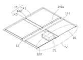
图1是本发明照明装置的一个较佳实施例的分解示意图。Fig. 1 is an exploded schematic diagram of a preferred embodiment of the lighting device of the present invention.
图2是图1中照明装置的组装示意图。Fig. 2 is a schematic diagram of the assembly of the lighting device in Fig. 1 .
图3是图2的翻转180度后的示意图。Fig. 3 is a schematic diagram of Fig. 2 turned over 180 degrees.
图4是图2沿IV-IV线的剖视示意图。FIG. 4 is a schematic cross-sectional view along line IV-IV of FIG. 2 .
图5是图4的部分放大示意图。FIG. 5 is a partially enlarged schematic view of FIG. 4 .
图6是图1所示的照明装置中光源的分解示意图。Fig. 6 is an exploded schematic diagram of a light source in the lighting device shown in Fig. 1 .
图7是图6的部分放大示意图。FIG. 7 is a partially enlarged schematic view of FIG. 6 .
具体实施方式Detailed ways
下面将结合附图对本发明实施例作进一步的详细说明。The embodiments of the present invention will be further described in detail below in conjunction with the accompanying drawings.
图1及图2所示为一种照明装置100,其包括:一个容置座10、四个光源20(图中仅示出一个光源)以及一个驱动电源40。FIG. 1 and FIG. 2 show a
所述容置座10呈矩形,其包括一个面板12以及设于面板12上的两个背板14。所述面板12和背板14间形成有四个用于收容光源20的容置空间16。The
请参阅图3至图5,所述面板12上对应所述容置空间16设有开口121,以使光源20所发出的光线可经由所述开口121射出。所述面板12包括延伸至所述容置空间16上方的凸伸部122,所述凸伸部122可将所述光源20卡设于容置空间16内,防止光源20由所述开口121处脱离出容置空间16。所述背板14在容置空间16的两个相对侧开设有与所述容置空间16相连通的开槽161,所述光源20经由该开槽161装设于容置空间16内,且经由设于所述背板14上的扣片141a固定于容置空间16内。所述扣片141a在光源20装设于容置空间16内之前与面板12相平行,当所述光源20装设于容置空间16内后,所述扣片141a被打弯至与面板12相垂直,将所述光源20固定至容置空间16内。Referring to FIGS. 3 to 5 , the
所述背板14包括两个平板部141、由平板部141沿朝向面板12的方向延伸的四个间隔部142、以及由间隔部142延伸出的三个固定部143。所述平板部141位于面板12的开口121的下方,其大小与光源20的大小基本相同。所述间隔部142由每一平板部141的前后两端沿垂直平板部141且朝向面板12的方向弯折形成,使所述平板部141与面板12间间隔一定的距离。所述固定部143由每一间隔部142沿垂直间隔部142的方向水平延伸形成,其中,位于背板14中间的固定部143的前后两端分别与该固定部143两侧的间隔部142相连。所述固定部143贴设于面板12的背面,并通过螺钉等固定元件或粘胶固定至面板12上,从而将背板14固定至面板12上。The
请一并参阅图6,所述光源20呈平板状,其包括一个透明平板24以及设于透明平板24侧边的一个线性的发光二极管阵列22。Please also refer to FIG. 6 , the
所述透明平板24呈正方形,其具有透光的特性,由聚甲基丙烯酸甲酯(polymethylmethacrylate,PMMA),聚碳酸酯(polycarbonate,PC),丙烯酸酯(polyacrylate),玻璃,树脂,硅树脂(silicone),环氧树脂(epoxy)等透明材料制成。所述透明平板24具有一个出光面241、以及与出光面241相对的一个背面242。所述透明平板24的出光面241可以是粗糙的雾面,或是具有网点图案的表面,或具有微小凹洞或凸起的表面,以将发光二极管阵列22所发出的光均匀的分布在透明平板24上,降低或消除炫光效果,不刺激人眼且达到柔和舒适的效果。所述出光面241可采用研磨、压印、喷砂、微机电(MEMs)、半导体制程或注塑成型等方法来制作。Described
所述发光二极管阵列22包括若干个发光二极管221,其通过弹性扣件26固定至透明平板24上。所述透明平板24的相对的另一侧对应该弹性扣件26设有另一个弹性扣件26,以保持透明平板24两侧的对称结构。The
所述弹性扣件26大致呈U形,由钢材、塑料等弹性材料制成,包括一个第一板体261、两个第二板体262以及两个第三板体263,所述第二板体262由第一平板体261两端倾斜延伸,所述第二板体262间的距离由第一板体261向远离第一板体261的方向递减,使得透明平板24的上、下两个表面分别与容置座10的面板12与背板14间隔一定的距离。所述第三板体263由所述第二板体262延伸且相互平行,所述透明平板12的侧边夹设于所述第三板体263之间,所述发光二极管221位于所述透明平板12和第一板体261之间。The
请一并参阅图7,所述发光二极管阵列22的左右两端各设有一个凸块222,所述凸块222上设有一个近似于U形的凹槽223,该凹槽223具有一个贯穿凸块222的右侧壁的开口端223a。所述弹性扣件26的第一板体261的左右两端开设有两个矩形穿孔261a,所述发光二极管阵列22的凸块222收容于该穿孔261a内,防止发光二极管阵列22在弹性扣件26内移动。当发光二极管阵列22的凸块222收容于弹性扣件26的穿孔261a时,连接所述发光二极管阵列22上的发光二极管221的导线(图未示)经由凸块222上凹槽223的开口端223a伸进凸块222的凹槽223内,并穿过弹性扣件26的穿孔261a。Please also refer to FIG. 7 , the left and right ends of the
所述照明装置100的各元件通过以下步骤进行安装:首先,将所述发光二极管阵列22的导线经由凹槽223的开口端223a置入凹槽223内,将所述发光二极管阵列22沿其纵向插设于该弹性扣件26的两个第二板体262之间,推动所述发光二极管阵列22向对应弹性扣件26的第一板体261滑动,直至发光二极管阵列22的凸块222收容于所述第一板体261的穿孔261a内,此时,发光二极管阵列22的导线随同发光二极管阵列22的凸块222穿过该弹性扣件26的穿孔261a;将弹性扣件26分别装设于透明平板24的两个相对侧,使透明平板24的两侧分别夹设于所述弹性扣件26的第三板体263之间,得到所述的光源20;将所述光源20插设于所述容置空间16的其中一个开槽161内,推动所述光源20向容置空间16内部滑动,直至所述光源20滑至与所述开槽161相对的另一个开槽161内,此时,所述光源20完全收容于所述容置空间16内;然后,向下打弯所述扣片141a,使其卡设于所述光源20的两个相对端,与光源20相抵靠,防止光源20由所述容置空间16内滑出。The components of the
拆卸时,只需将所述扣片141a拉直,然后向外拉动所述光源20,直至所述光源20由所述容置空间16中脱离即可。When disassembling, it is only necessary to straighten the
本实施例中,只需通过扣片141a的打弯或拉直即可实现光源20的安装和拆卸,使该光源20的安装、拆卸和替换较为方便,从而使得所述照明装置100不致因光源20的损坏而报废。另外,也提升了所述照明装置100的兼容性,使所述平面装置可适应不同画面内容的光源20。In this embodiment, the installation and disassembly of the
本实施例中,所述弹性扣件26的第二板体262倾斜设置,使得光源20的出光面241与背面242分别与容置座10的面板12与背板14间隔一定的距离,为容置座10提供了一定的变形空间,使所述光源20不致因容置座10受到的冲击而损坏,有效地保护了光源20,延长了光源20的使用寿命。In this embodiment, the second plate body 262 of the
本实施例中,发光二极管阵列22设于透明平板24的右侧,可以理解地,所述发光二极管阵列22也可以设于透明平板24的左侧,或同时设于透明平板24的左右两侧。In this embodiment, the light-emitting
本实施例中,所述发光二极管阵列22包括若干个发光二极管221,可以理解地,可以利用有机发光二极管等固态发光元件来代替所述发光二极管以组成固态发光元件阵列。In this embodiment, the light
本实施例中,透明平板24的出光面241为粗糙的表面,可以理解地,所述出光面241也可以为一平面,当所述出光面241为平面时,为达到均匀分布光线的效果,该透明平板24内掺杂有不同折射率的微粒物质,如氧化铝(Al2O3)、氧化钛(TiO2)、氧化硅(SiO2)、氮化硅(SiNX)、氟化钙(CaF2)、硫酸钡(BaSO4)、氧化锌(ZnO)、氧化硼(B2O3)、氧化铌(Nb2O5)、氧化钠(Na2O)、氧化锂(Li2O)等,以将发光二极管阵列22所发出的光偏折以造成散射效果,从而使光均匀分布。当所述出光面241为平面时,在透明平板24内设置孔隙或缺陷,也可使由出光面241射出的光达到均匀分布的效果。上述缺陷可通过一高能量密度的电磁波照射该透明平板24的内部,使其内部物质受到破坏而产生微小的缺陷,经过所述电磁波的多次照射,即可得到其内部形成有缺陷的透明平板24。In this embodiment, the light-emitting
本实施例中,所述容置座10包括两个背板14,可以理解地,所述两个背板14可以合二为一成为一个盖设于面板12上的背板14。当然,所述单个背板14也可以拆分为两个相分离的背板14,使所述容置座10包括分别对应于所述面板12的开口121的四个背板14。In this embodiment, the
本实施例中,所述背板14的平板部141的两侧设有两个开槽161,并在设置开槽161的两侧设置扣片141a,可以理解地,所述平板部141可以仅在其一侧设置开槽161和扣片141a,而在与开槽161相对的另一侧设置间隔部142,使得所述平板部141的另一侧封闭,可同样将光源20装设于容置座10上。In this embodiment, two
另外,本领域技术人员还可于本发明精神内做其它变化,如容置座的结构,光源的数量以及排布方式等以用于本发明等设计,只要其不偏离本发明的技术效果均可。这些依据本发明精神所做的变化,都应包含在本发明所要求保护的范围之内。In addition, those skilled in the art can also make other changes within the spirit of the present invention, such as the structure of the accommodating seat, the number and arrangement of light sources, etc. for the design of the present invention, as long as it does not deviate from the technical effects of the present invention. Can. These changes made according to the spirit of the present invention should be included in the scope of protection of the present invention.
Claims (14)
Priority Applications (4)
| Application Number | Priority Date | Filing Date | Title |
|---|---|---|---|
| CN2007102031574ACN101463971B (en) | 2007-12-18 | 2007-12-18 | Illuminating apparatus |
| US12/261,285US8016454B2 (en) | 2007-12-18 | 2008-10-30 | Light emitting diode illuminator |
| AT08254031TATE510170T1 (en) | 2007-12-18 | 2008-12-17 | LIGHTING DEVICE |
| EP08254031AEP2072891B1 (en) | 2007-12-18 | 2008-12-17 | Illumination device |
Applications Claiming Priority (1)
| Application Number | Priority Date | Filing Date | Title |
|---|---|---|---|
| CN2007102031574ACN101463971B (en) | 2007-12-18 | 2007-12-18 | Illuminating apparatus |
Publications (2)
| Publication Number | Publication Date |
|---|---|
| CN101463971A CN101463971A (en) | 2009-06-24 |
| CN101463971Btrue CN101463971B (en) | 2010-11-10 |
Family
ID=40351616
Family Applications (1)
| Application Number | Title | Priority Date | Filing Date |
|---|---|---|---|
| CN2007102031574AExpired - Fee RelatedCN101463971B (en) | 2007-12-18 | 2007-12-18 | Illuminating apparatus |
Country Status (4)
| Country | Link |
|---|---|
| US (1) | US8016454B2 (en) |
| EP (1) | EP2072891B1 (en) |
| CN (1) | CN101463971B (en) |
| AT (1) | ATE510170T1 (en) |
Families Citing this family (6)
| Publication number | Priority date | Publication date | Assignee | Title |
|---|---|---|---|---|
| WO2010083341A2 (en)* | 2009-01-14 | 2010-07-22 | Abl Ip Holding, Llc | Luminaire having floating luminous light source |
| DE102010062331B4 (en) | 2010-12-02 | 2012-07-05 | Osram Ag | Manufacturing method for an LED lamp and a corresponding LED lamp |
| US20120170266A1 (en)* | 2011-01-04 | 2012-07-05 | GE Lighting Solutions, LLC | Edge-lit modular ceiling tile light fixtures |
| US20150103258A1 (en)* | 2012-07-03 | 2015-04-16 | Sharp Kabushiki Kaisha | Lighting device, display device and television device |
| TWI603030B (en)* | 2016-12-26 | 2017-10-21 | 機光科技股份有限公司 | Planar oled lamp module |
| CN114698313B (en)* | 2020-12-31 | 2023-11-14 | Oppo广东移动通信有限公司 | Electronic equipment |
Citations (2)
| Publication number | Priority date | Publication date | Assignee | Title |
|---|---|---|---|---|
| CN1991237A (en)* | 2005-12-28 | 2007-07-04 | 三菱电机株式会社 | Surface light source device and display device using same |
| CN101004510A (en)* | 2006-01-18 | 2007-07-25 | 三菱电机株式会社 | Planar light source unit and image display apparatus using the same |
Family Cites Families (27)
| Publication number | Priority date | Publication date | Assignee | Title |
|---|---|---|---|---|
| JP2509660B2 (en) | 1988-03-12 | 1996-06-26 | ファナック株式会社 | LED display module |
| US6712481B2 (en)* | 1995-06-27 | 2004-03-30 | Solid State Opto Limited | Light emitting panel assemblies |
| US5736744A (en)* | 1996-03-27 | 1998-04-07 | Uvp, Inc. | Wavelength shifting filter |
| JP2000215715A (en) | 1999-01-22 | 2000-08-04 | Motoyuki Suzuki | Light panel cover |
| US6476883B1 (en)* | 2000-05-05 | 2002-11-05 | Adaptive Micro Systems, Inc. | Enclosure system for electronic displays and method for making same |
| TWI243940B (en)* | 2000-11-01 | 2005-11-21 | Au Optronics Corp | Housing for flat panel display and method for assembly the same |
| TW546491B (en) | 2001-02-21 | 2003-08-11 | Au Optronics Corp | Light source set with a uniform temperature function and flat display |
| TW567619B (en) | 2001-08-09 | 2003-12-21 | Matsushita Electric Industrial Co Ltd | LED lighting apparatus and card-type LED light source |
| CN1384391A (en)* | 2002-05-27 | 2002-12-11 | 胜华科技股份有限公司 | The structure of the backlight module |
| KR100840715B1 (en)* | 2002-05-28 | 2008-06-23 | 삼성전자주식회사 | Back light assembly and liquid crystal display device having the same |
| US6691443B1 (en) | 2002-09-20 | 2004-02-17 | Lektron, Inc. | Alpha-numeric/graphic display board illuminator |
| US7095457B2 (en)* | 2002-12-09 | 2006-08-22 | Shin Jiuh Corp. | LCD television with detachable backlight module |
| TW576511U (en)* | 2003-03-21 | 2004-02-11 | Hon Hai Prec Ind Co Ltd | Backlight module and the housing thereof |
| JP4321191B2 (en)* | 2003-09-18 | 2009-08-26 | セイコーエプソン株式会社 | Liquid crystal display |
| KR100970268B1 (en)* | 2003-10-11 | 2010-07-16 | 삼성전자주식회사 | Back light assembly and display device having same |
| TWI226494B (en)* | 2003-12-03 | 2005-01-11 | Quanta Display Inc | Back-light module |
| TWI307433B (en)* | 2004-05-12 | 2009-03-11 | Au Optronics Corp | Backlight module |
| JP2008108424A (en) | 2005-02-14 | 2008-05-08 | Sharp Corp | Backlight device and display device using the same |
| TWI272435B (en)* | 2005-10-21 | 2007-02-01 | Polarlite Corp | Illuminant device |
| US7226201B1 (en)* | 2005-12-02 | 2007-06-05 | Radiant Opto-Electronics Corporation | Frame structure for backlight module |
| US7547112B2 (en)* | 2005-12-12 | 2009-06-16 | Led Folio Corporation | Low-clearance light emitting diode lighting |
| US20070189039A1 (en)* | 2006-02-10 | 2007-08-16 | Seiko Epson Corporation | Light guide plate, mold for forming light guide plate, and method for manufacturing a mold for forming light guide plate |
| JP2007233251A (en)* | 2006-03-03 | 2007-09-13 | Mitsubishi Electric Corp | Display device |
| CN101122703B (en)* | 2006-08-11 | 2010-12-01 | 鸿富锦精密工业(深圳)有限公司 | Optical board and backlight module using the optical board |
| TW200811522A (en)* | 2006-08-22 | 2008-03-01 | Chunghwa Picture Tubes Ltd | Light-source fixing structure for backlight module |
| US7671936B2 (en)* | 2006-09-21 | 2010-03-02 | Hannstar Display Corp. | Liquid crystal display comprising at least one LED and a PCB and a frame having an opening with a narrow portion and a broad portion on a side surface of the frame and backlight module having the same |
| KR20080035043A (en)* | 2006-10-18 | 2008-04-23 | 삼성전자주식회사 | Back light assembly and display device having same |
- 2007
- 2007-12-18CNCN2007102031574Apatent/CN101463971B/ennot_activeExpired - Fee Related
- 2008
- 2008-10-30USUS12/261,285patent/US8016454B2/ennot_activeExpired - Fee Related
- 2008-12-17ATAT08254031Tpatent/ATE510170T1/ennot_activeIP Right Cessation
- 2008-12-17EPEP08254031Apatent/EP2072891B1/ennot_activeNot-in-force
Patent Citations (2)
| Publication number | Priority date | Publication date | Assignee | Title |
|---|---|---|---|---|
| CN1991237A (en)* | 2005-12-28 | 2007-07-04 | 三菱电机株式会社 | Surface light source device and display device using same |
| CN101004510A (en)* | 2006-01-18 | 2007-07-25 | 三菱电机株式会社 | Planar light source unit and image display apparatus using the same |
Also Published As
| Publication number | Publication date |
|---|---|
| US8016454B2 (en) | 2011-09-13 |
| ATE510170T1 (en) | 2011-06-15 |
| CN101463971A (en) | 2009-06-24 |
| US20090154170A1 (en) | 2009-06-18 |
| EP2072891A1 (en) | 2009-06-24 |
| EP2072891B1 (en) | 2011-05-18 |
Similar Documents
| Publication | Publication Date | Title |
|---|---|---|
| CN101463971B (en) | Illuminating apparatus | |
| EP2527725B1 (en) | Lighting module | |
| TWI225543B (en) | Light emitting panel assemblies | |
| TWI417605B (en) | Liquid crystal display | |
| CN101684897B (en) | Back light unit and liquid crystal display using the same | |
| TWI526652B (en) | Lighting device | |
| US8944644B2 (en) | Lens module and LED illumination device using the same | |
| TWI428535B (en) | Condenser lighting device | |
| TW200706920A (en) | Light diffusing plate and lighting device using it | |
| US9733423B2 (en) | Backlight assembly and display device having the same | |
| EP2495490B1 (en) | Led lighting device which has stable structure and is easily assembled and disassembled | |
| KR101219591B1 (en) | Back light guide plate and manufacturing method for the same | |
| CN101600902A (en) | Planar illuminating device | |
| CN202548488U (en) | Liquid crystal display device | |
| TW201132893A (en) | Lighting device | |
| KR20130074549A (en) | Direct type liquid crystal display device having supportable lens | |
| EP2322973A1 (en) | Lens and light emitting diode lamp using same | |
| JP2007250273A (en) | Light guide plate unit | |
| KR101681327B1 (en) | Display apparatus | |
| JP2019063708A (en) | Light irradiation device | |
| CN101713518B (en) | Illuminator | |
| KR20180099956A (en) | Liquid crystal display device | |
| TWI358513B (en) | Illuminator | |
| CN101644414A (en) | Illumination device | |
| JP5401641B2 (en) | Floor-buried guide light device |
Legal Events
| Date | Code | Title | Description |
|---|---|---|---|
| C06 | Publication | ||
| PB01 | Publication | ||
| C10 | Entry into substantive examination | ||
| SE01 | Entry into force of request for substantive examination | ||
| C14 | Grant of patent or utility model | ||
| GR01 | Patent grant | ||
| C17 | Cessation of patent right | ||
| CF01 | Termination of patent right due to non-payment of annual fee | Granted publication date:20101110 Termination date:20101218 |