CN101461091A - Radio wave lens antenna device - Google Patents
Radio wave lens antenna deviceDownload PDFInfo
- Publication number
- CN101461091A CN101461091ACNA2006800548679ACN200680054867ACN101461091ACN 101461091 ACN101461091 ACN 101461091ACN A2006800548679 ACNA2006800548679 ACN A2006800548679ACN 200680054867 ACN200680054867 ACN 200680054867ACN 101461091 ACN101461091 ACN 101461091A
- Authority
- CN
- China
- Prior art keywords
- lens
- lid
- antenna device
- cover
- radiowave
- Prior art date
- Legal status (The legal status is an assumption and is not a legal conclusion. Google has not performed a legal analysis and makes no representation as to the accuracy of the status listed.)
- Pending
Links
- XLYOFNOQVPJJNP-UHFFFAOYSA-NwaterSubstancesOXLYOFNOQVPJJNP-UHFFFAOYSA-N0.000claimsabstractdescription60
- 230000004888barrier functionEffects0.000claimsdescription30
- 238000011282treatmentMethods0.000claimsdescription16
- 230000002209hydrophobic effectEffects0.000claimsdescription12
- 239000000463materialSubstances0.000claimsdescription5
- 239000011521glassSubstances0.000claimsdescription4
- 239000005060rubberSubstances0.000claimsdescription4
- 229920003002synthetic resinPolymers0.000claimsdescription4
- 239000000057synthetic resinSubstances0.000claimsdescription4
- 239000000835fiberSubstances0.000claimsdescription3
- 230000005283ground stateEffects0.000claims3
- 150000001875compoundsChemical class0.000claims1
- 238000007789sealingMethods0.000claims1
- 230000035945sensitivityEffects0.000abstractdescription11
- 239000005871repellentSubstances0.000description9
- 239000005413snowmeltSubstances0.000description6
- 239000011248coating agentSubstances0.000description5
- 238000000576coating methodMethods0.000description5
- 229920005989resinPolymers0.000description5
- 239000011347resinSubstances0.000description5
- 238000009825accumulationMethods0.000description4
- 230000002411adverseEffects0.000description4
- 230000000694effectsEffects0.000description4
- 238000002474experimental methodMethods0.000description3
- 239000006260foamSubstances0.000description3
- 239000000155meltSubstances0.000description3
- 230000000052comparative effectEffects0.000description2
- 239000002131composite materialSubstances0.000description2
- 230000000593degrading effectEffects0.000description2
- 239000004744fabricSubstances0.000description2
- 238000005187foamingMethods0.000description2
- 238000005259measurementMethods0.000description2
- 238000002844meltingMethods0.000description2
- 230000008018meltingEffects0.000description2
- 239000012188paraffin waxSubstances0.000description2
- 229920000178Acrylic resinPolymers0.000description1
- 239000004925Acrylic resinSubstances0.000description1
- 230000009286beneficial effectEffects0.000description1
- 238000004891communicationMethods0.000description1
- 239000006185dispersionSubstances0.000description1
- 239000005457ice waterSubstances0.000description1
- 238000009434installationMethods0.000description1
- 238000000034methodMethods0.000description1
- 230000004048modificationEffects0.000description1
- 238000012986modificationMethods0.000description1
- 238000000465mouldingMethods0.000description1
- 229920005668polycarbonate resinPolymers0.000description1
- 239000004431polycarbonate resinSubstances0.000description1
- 229920005672polyolefin resinPolymers0.000description1
- 238000011176poolingMethods0.000description1
- 230000009467reductionEffects0.000description1
- 230000002195synergetic effectEffects0.000description1
Images


Classifications
- H—ELECTRICITY
- H01—ELECTRIC ELEMENTS
- H01Q—ANTENNAS, i.e. RADIO AERIALS
- H01Q15/00—Devices for reflection, refraction, diffraction or polarisation of waves radiated from an antenna, e.g. quasi-optical devices
- H01Q15/02—Refracting or diffracting devices, e.g. lens, prism
- H01Q15/08—Refracting or diffracting devices, e.g. lens, prism formed of solid dielectric material
- H—ELECTRICITY
- H01—ELECTRIC ELEMENTS
- H01Q—ANTENNAS, i.e. RADIO AERIALS
- H01Q1/00—Details of, or arrangements associated with, antennas
- H01Q1/42—Housings not intimately mechanically associated with radiating elements, e.g. radome
- H—ELECTRICITY
- H01—ELECTRIC ELEMENTS
- H01Q—ANTENNAS, i.e. RADIO AERIALS
- H01Q1/00—Details of, or arrangements associated with, antennas
- H01Q1/42—Housings not intimately mechanically associated with radiating elements, e.g. radome
- H01Q1/421—Means for correcting aberrations introduced by a radome
- H—ELECTRICITY
- H01—ELECTRIC ELEMENTS
- H01Q—ANTENNAS, i.e. RADIO AERIALS
- H01Q19/00—Combinations of primary active antenna elements and units with secondary devices, e.g. with quasi-optical devices, for giving the antenna a desired directional characteristic
- H01Q19/06—Combinations of primary active antenna elements and units with secondary devices, e.g. with quasi-optical devices, for giving the antenna a desired directional characteristic using refracting or diffracting devices, e.g. lens
- H01Q19/062—Combinations of primary active antenna elements and units with secondary devices, e.g. with quasi-optical devices, for giving the antenna a desired directional characteristic using refracting or diffracting devices, e.g. lens for focusing
- H—ELECTRICITY
- H01—ELECTRIC ELEMENTS
- H01Q—ANTENNAS, i.e. RADIO AERIALS
- H01Q3/00—Arrangements for changing or varying the orientation or the shape of the directional pattern of the waves radiated from an antenna or antenna system
- H01Q3/02—Arrangements for changing or varying the orientation or the shape of the directional pattern of the waves radiated from an antenna or antenna system using mechanical movement of antenna or antenna system as a whole
- H01Q3/04—Arrangements for changing or varying the orientation or the shape of the directional pattern of the waves radiated from an antenna or antenna system using mechanical movement of antenna or antenna system as a whole for varying one co-ordinate of the orientation
Landscapes
- Details Of Aerials (AREA)
- Aerials With Secondary Devices (AREA)
Abstract
Translated fromChinese
Description
Translated fromChinese技术领域technical field
本发明涉及一种采用伦伯透镜的无线电波透镜天线设备,并且更具体地涉及一种防止当下雨或雪融化时信号接收灵敏度降低的无线电波透镜天线设备。The present invention relates to a radio wave lens antenna device using a Lunburg lens, and more particularly, to a radio wave lens antenna device that prevents a reduction in signal reception sensitivity when rain or snow melts.
背景技术Background technique
期望采用伦伯(Luneburg)透镜的无线电波透镜天线能用作能够同时与多个通信同位体进行通讯的可适应多光束的天线设备。而且,这种无线电波透镜天线已经能够代替作为同步卫星天线设备的抛物面天线。It is expected that a radio wave lens antenna employing a Luneburg lens can be used as an adaptable multi-beam antenna device capable of simultaneously communicating with a plurality of communication peers. Also, this radio wave lens antenna has been able to replace the parabolic antenna as a geostationary satellite antenna device.
由电介质形成的伦伯透镜基本上具有球形的形状。然而,为使无线电波透镜小型化,半球形伦伯透镜可以和大于半球形伦伯透镜直径的无线电波反射板(下文中简称为反射板)结合使用,以形成具有的功能等同于球形伦伯透镜功能的无线电波透镜。和反射板结合的这种天线设备可以设置在面向目标同步卫星的任何地方,其中,反射板保持在直立状态。例如,天线设备可以设置在建筑物的墙壁表面上或阳台的围墙上。天线设备还可以设置在建筑物的房顶,其中,反射板平行于地面。因此,天线设备具有高水平的设置自由度。A Lunberian lens formed of a dielectric substantially has a spherical shape. However, in order to miniaturize the radio wave lens, a hemispherical Lunberian lens may be used in combination with a radio wave reflecting plate (hereinafter simply referred to as a reflecting plate) larger than the diameter of the hemispherical Lunberian lens to form a The radio wave lens of the lens function. Such an antenna device combined with a reflector can be placed anywhere facing the target geostationary satellite, wherein the reflector is kept upright. For example, the antenna device may be provided on a wall surface of a building or on a fence of a balcony. The antenna device can also be arranged on the roof of a building, wherein the reflecting plate is parallel to the ground. Therefore, the antenna device has a high level of freedom of arrangement.
在采用伦伯透镜的天线设备中,防水的盖子覆盖透镜的外表面。例如,下面列出的专利公开文献1公开了一种与伦伯透镜整体形成的半球形雷达天线罩。而且,下面列出的专利公开文献2公开了一种覆盖包括天线元件的整个天线设备的雷达天线罩。此外,下面列出的专利公开文献3公开了一种覆盖半球形透镜的半球形盖子。In an antenna device employing a Lunburg lens, a waterproof cover covers the outer surface of the lens. For example,
以这种方式,雷达天线罩或半球形盖子覆盖透镜。因此,尤其是在耐用性方面不存在问题,即使是在由于下雨而潮湿而。然而,当使用期间下落的雨水聚集在透镜上或从透镜表面(表面保护层的外表面)流走时,C/N衰减量(信号和噪音的功率比)增加并降低无线电波的信号接收灵敏度。而且,当透镜上的雪或透镜上的冰融化时,水从透镜表面流走。这也会降低无线电波的信号接收灵敏度。In this way, the radome or hemispherical cover covers the lens. Therefore, there is no problem especially in terms of durability, even when it is wet due to rain. However, when rainwater falling during use collects on the lens or runs away from the lens surface (outer surface of the surface protection layer), the amount of C/N attenuation (power ratio of signal to noise) increases and reduces signal reception sensitivity of radio waves. Also, when snow on the lens or ice on the lens melts, water runs off the surface of the lens. This also reduces the signal reception sensitivity of radio waves.
未考虑到现有技术的无线电波透镜天线设备中存在的这种问题。因此,存在信号接收灵敏度变低的趋势。而且,当采用雷达天线罩覆盖整个天线设备时,必须增加雷达天线罩的厚度以确保所需的强度。因此,雷达天线罩不良地影响了电性能,增加了尺寸和重量并增加成本。Such problems in prior art radio wave lens antenna devices are not taken into account. Therefore, there is a tendency for signal reception sensitivity to become low. Also, when the entire antenna device is covered with a radome, it is necessary to increase the thickness of the radome to secure required strength. Therefore, the radome adversely affects electrical performance, increases size and weight, and increases cost.
专利公开文献1:日本专利特许公开第50-116259号Patent publication 1: Japanese Patent Laid-Open No. 50-116259
专利公开文献2:日本专利特许公开第2000-183645号Patent publication 2: Japanese Patent Laid-Open No. 2000-183645
专利公开文献3:日本专利特许公开第2002-232230号Patent publication 3: Japanese Patent Laid-Open No. 2002-232230
专利公开文献4:日本专利特许公开第2004-282718号Patent publication 4: Japanese Patent Laid-Open No. 2004-282718
发明内容Contents of the invention
本发明所要解决的技术问题Technical problem to be solved by the present invention
上面列出的专利公开文献4描述了一种采用伦伯透镜的同步卫星天线设备的示例。当用作接收来自同步卫星的无线电波的天线时,该天线设备性能是极其出众的。然而,当下雨或雪融化时,该天线设备容易受到聚集在伦伯透镜上或从伦伯透镜流走的水的影响。因此,存在信号接收灵敏度变低的趋势。
本发明的目的是提供一种无线电波透镜天线设备,该设备通过防止雨水和融雪降低信号接收灵敏度而提高可靠性。An object of the present invention is to provide a radio wave lens antenna device which improves reliability by preventing rainwater and melting snow from degrading signal reception sensitivity.
解决技术问题的技术方案Technical solutions to technical problems
为解决上述问题,在本发明中,一种无线电波透镜天线设备包括半球形伦伯透镜、沿透镜的球体的二分表面摆放并具有大于透镜直径的尺寸的无线电波反射板、天线元件、以及保持所述天线元件的保持器。所述无线电波透镜天线设备包括防冰-雪-水装置,该防冰-雪-水装置防止雨、雪和冰聚集在伦伯透镜表面上并防止水从伦伯透镜流走。In order to solve the above-mentioned problems, in the present invention, a radio wave lens antenna device includes a hemispherical Lunburg lens, a radio wave reflecting plate disposed along a bisected surface of a sphere of the lens and having a size larger than the diameter of the lens, an antenna element, and A holder that holds the antenna element. The radio wave lens antenna apparatus includes an ice-snow-water protection device that prevents rain, snow, and ice from accumulating on the surface of the Lumber lens and that prevents water from flowing away from the Lumber lens.
防冰-雪-水装置的具体实施例为覆盖部分所述无线电波透镜天线设备的盖子。在反射板直立在地面上的状态下盖子的优选实施例覆盖整个伦伯透镜,并且所述盖子包括以大于伦伯透镜上部的倾斜角度的角度倾斜的上部,或者在反射板平行于地面的状态下所述盖子覆盖所述伦伯透镜的上部,并且所述盖子包括以大于所述伦伯透镜表面的倾斜角度的角度倾斜的表面。基于将透镜半球形表面上的点连接到透镜中心的线延伸的倾斜,在延伸与盖子交叉的点处将盖子表面的倾斜角度和透镜表面的倾斜角度进行比较(相对于地面在接触每一对比点的表面处的倾斜角度)。A specific embodiment of the ice-snow-water protection device is a cover covering part of the radio wave lens antenna device. A preferred embodiment of the cover covers the entire Lunburg lens in a state where the reflector is upright on the ground, and the cover includes an upper portion inclined at an angle greater than that of the upper portion of the Lunburg lens, or in a state where the reflector is parallel to the ground The lower cover covers an upper portion of the Lunburg lens, and the cover includes a surface inclined at an angle greater than an inclination angle of a surface of the Lunburg lens. Based on the inclination of the line extension connecting a point on the lens hemispherical surface to the center of the lens, the inclination angle of the cover surface is compared to the inclination angle of the lens surface at the point where the extension intersects the cover (relative to the ground at contacting each contrast The angle of inclination at the surface of the point).
而且,所述盖子包括:第一盖子,在反射板直立在地面上的状态下,所述第一盖子覆盖伦伯透镜;以及第二盖子,该第二盖子覆盖所述第一盖子的上部,所述第二盖子具有以大于所述第一盖子上部的倾斜角度的角度倾斜的上部。在这种情况下,优选所述第二盖子具有与透镜分离并低于透镜中心的下端。基于将第一盖子表面上的点连接到透镜中心的线延伸的倾斜,在延伸与第二盖子交叉的点处将第二盖子表面的倾斜角度和第一盖子表面的倾斜角度进行比较(相对于地面在接触每一对比点的表面处的倾斜角度)。Also, the cover includes: a first cover covering the Lunburg lens in a state where the reflecting plate stands upright on the ground; and a second cover covering an upper portion of the first cover, The second cover has an upper portion inclined at an angle greater than that of the upper portion of the first cover. In this case, it is preferable that the second cover has a lower end separated from the lens and lower than the center of the lens. Based on the inclination of a line extension connecting a point on the first cover surface to the center of the lens, the inclination angle of the second cover surface is compared to the inclination angle of the first cover surface at the point where the extension intersects the second cover surface (relative to The angle of inclination of the ground at the surface touching each contrast point).
所述盖子包括:第一半球形盖子,在反射板平行于地面的状态下,所述第一半球形盖子覆盖伦伯透镜;以及第二盖子,该第二盖子覆盖所述第一盖子的上部,所述第二盖子具有以大于所述第一盖子上部的倾斜角度的角度倾斜的上部。这能够用在将反射板平行于地面设置的天线设备中。The cover includes: a first hemispherical cover covering the Lunburg lens in a state where the reflection plate is parallel to the ground; and a second cover covering an upper portion of the first cover , the second cover has an upper portion inclined at an angle greater than that of the upper portion of the first cover. This can be used in an antenna arrangement in which the reflecting plate is arranged parallel to the ground.
防冰-雪-水装置包括形成于覆盖伦伯透镜的盖子的表面上的屏障,所述屏障位于连接天线元件和透镜中心的直线的上方并在预定范围内横向延伸。在这种情况下,所述屏障包括凹槽、凸起和台阶中的一个。优选屏障位于面向天线元件的盖子表面部分上方并高出地面的位置,并且屏障朝向该屏障两端逐渐降低。还优选屏障具有已经过拒水处理的表面。The ice-snow-water protection device includes a barrier formed on a surface of a cover covering the Lunburg lens, the barrier being located above a line connecting the antenna element and the center of the lens and extending laterally within a predetermined range. In this case, the barrier includes one of a groove, a protrusion, and a step. Preferably the barrier is positioned above the portion of the cover surface facing the antenna elements and raised above the ground, and the barrier is gradually lowered towards the ends of the barrier. It is also preferred that the barrier has a surface that has been treated to repel water.
防冰-雪-雨设备可以包括设置在天线元件和伦伯透镜之间的盖子,以便在面向天线元件的区域覆盖天线设备和伦伯透镜表面。The ice-snow-rain protection device may comprise a cover arranged between the antenna element and the Lunburg lens so as to cover the antenna device and the Lunburg lens surface in an area facing the antenna element.
防冰-雪-水装置可以包括护罩,在反射板直立在地面上的状态下,所述护罩设置在伦伯透镜上方并且从伦伯透镜的半径向外延伸。反射板可以从该反射板垂直于地面的直立位置开始向前倾斜,从而倾斜的反射板也用作护罩。The ice-snow-water protection device may include a shroud disposed over the Lunburg lens and extending outward from a radius of the Lunburg lens in a state where the reflective plate is upright on the ground. From an upright position where the reflector is perpendicular to the ground, the reflector can be tilted forward so that the tilted reflector also acts as a shield.
以下是防冰-雪-水装置的示例:The following are examples of ice-snow-water protection:
覆盖部分天线设备并具有已经过拒水处理和亲水处理中的一个或两个处理的表面的盖子;A cover covering part of the antenna device and having a surface that has been treated with one or both of a water-repellent treatment and a hydrophilic treatment;
覆盖伦伯透镜的半球形盖子,所述半球形盖子包括已经过亲水处理的顶部和已经过拒水处理的排除所述顶部的之外的上部;a hemispherical cover covering the Lunburg lens, the hemispherical cover comprising a top portion that has been treated for hydrophilicity and an upper portion that has been treated for water repellency excluding the top portion;
覆盖部分天线设备的盖子,所述盖子包括已经过亲水处理和拒水处理从而使岛状的疏水部分分散在亲水部分中的表面,其中,所述疏水部分的面积优选大于所述亲水部分的面积;以及A cover covering part of the antenna device, the cover comprising a surface that has undergone hydrophilic treatment and water-repellent treatment so that island-shaped hydrophobic parts are dispersed in the hydrophilic part, wherein the area of the hydrophobic part is preferably larger than that of the hydrophilic part the area of the portion; and
由合成树脂、橡胶、纤维、玻璃或者这些材料的复合物形成的盖子。可以使用合成树脂泡沫、橡胶和玻璃。A cover formed of synthetic resin, rubber, fiber, glass, or a composite of these materials. Synthetic resin foam, rubber and glass can be used.
本发明的有益效果Beneficial effects of the present invention
根据本发明的无线电波透镜天线设备包括盖子,该盖子覆盖部分天线设备以作为防止雨、雪和冰聚集在伦伯透镜表面上或者水向前流到天线元件的防冰-雪-水装置。这防止雨水和融雪聚集在透镜表面上。包括设置在盖子表面上的屏障的无线电波透镜天线设备不用于防止雨、雪和冰聚集。然而,沿盖子表面流动的雨水或融雪被引导到屏障或被屏障停止,并因此不流经无线电波朝向天线元件传播的路径。因此,本发明减少了聚集的雨水、雪和冰。而且,雨水和融雪以及冰不流向大大影响天线信号接收灵敏度的位置,即对应于天线元件的透镜表面上的位置。因此,被流经的水影响信号接收灵敏度巧妙地降低。The radio wave lens antenna device according to the present invention includes a cover which covers a part of the antenna device as an ice-snow-water preventing means for preventing rain, snow and ice from accumulating on the surface of the Lumber lens or water flowing forward to the antenna element. This prevents rainwater and snowmelt from collecting on the lens surface. The radio wave lens antenna device including the barrier provided on the surface of the cover is not used to prevent accumulation of rain, snow and ice. However, rainwater or snowmelt flowing along the surface of the cover is guided to or stopped by the barrier, and thus does not flow through a path where radio waves propagate toward the antenna element. Thus, the present invention reduces the accumulation of rain, snow and ice. Also, rainwater and snowmelt and ice do not flow to a position that greatly affects antenna signal reception sensitivity, that is, a position on the lens surface corresponding to the antenna element. Therefore, the signal reception sensitivity is subtly reduced by passing water.
附图说明Description of drawings
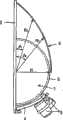
图1是示出应用本发明的无线电波透镜天线设备的示意性透视图;1 is a schematic perspective view showing a radio wave lens antenna device to which the present invention is applied;
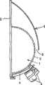
图2是示出根据本发明的无线电波透镜天线设备的一个实施例的侧视图;2 is a side view showing one embodiment of a radio wave lens antenna device according to the present invention;
图3是示出另一实施例的局部剖切侧视图;Figure 3 is a partially cutaway side view showing another embodiment;
图4是示出又一实施例的局部剖切侧视图;Figure 4 is a partially cutaway side view showing yet another embodiment;
图5是示出又一实施例的侧视图;Fig. 5 is a side view showing yet another embodiment;
图6是示出又一实施例的局部剖切侧视图;Figure 6 is a partially cutaway side view showing yet another embodiment;
图7是示出又一实施例的局部剖切侧视图;Figure 7 is a partially cutaway side view showing yet another embodiment;
图8是示出又一实施例的局部剖切侧视图;Fig. 8 is a partially cutaway side view showing yet another embodiment;
图9是示出带肋盖子的一个示例的透视图;Figure 9 is a perspective view showing an example of a ribbed cover;
图10是示出又一实施例的透视图;Fig. 10 is a perspective view showing yet another embodiment;
图11是示出又一实施例的侧视图;Fig. 11 is a side view showing yet another embodiment;
图12是示出又一实施例的局部剖切侧视图;Fig. 12 is a partially cutaway side view showing yet another embodiment;
图13是示出又一实施例的侧视图;Figure 13 is a side view showing yet another embodiment;
图14是示出又一实施例的侧视图;Figure 14 is a side view showing yet another embodiment;
图15是示出又一实施例的侧视图;Fig. 15 is a side view showing yet another embodiment;
图16是示出又一实施例的侧视图;Figure 16 is a side view showing yet another embodiment;
图17(a)-17(e)是示屏障的横截面形状的视图;17(a)-17(e) are views showing the cross-sectional shape of the barrier;
图18(a)-18(c)是示屏障安装状态的前视图;Figure 18 (a)-18 (c) is the front view showing the barrier installation state;
图19是示出又一实施例的侧视图;Fig. 19 is a side view showing yet another embodiment;
图20是示出又一实施例的侧视图;Figure 20 is a side view showing yet another embodiment;
图21是示出又一实施例的透视图;Figure 21 is a perspective view showing yet another embodiment;
图22是示出又一实施例的透视图;Figure 22 is a perspective view showing yet another embodiment;
图23是示出又一实施例的透视图;Figure 23 is a perspective view showing yet another embodiment;
图24是示出又一实施例的侧视图;Figure 24 is a side view showing yet another embodiment;
图25是示出又一实施例的侧视图;以及Figure 25 is a side view showing yet another embodiment; and
图26为是示在用于检查效果的实验中使用的测量系统的视图。Fig. 26 is a view showing a measurement system used in an experiment for checking the effect.
附图标记说明Explanation of reference signs
1 伦伯透镜1 Lumber lens
2 反射板2 reflector
3 天线元件3 antenna elements
4 保持器4 retainer
5、5A 第一盖子5. 5A first cover
6、12 第二盖子6, 12 Second cover
6a 裙6a skirt
6b 法兰6b Flange
6c 竖直肋6c vertical rib
6d 水平肋6d horizontal rib
7 盖子(雷达天线罩)7 cover (radome)
8 护罩8 shield
9、13 屏障9, 13 Barriers
9a 凹槽9a Groove
9b 凸起9b Raised
9c 台阶9c steps
10 亲水部分10 Hydrophilic part
11 疏水部分11 Hydrophobic part
14 开口14 opening
15 第三盖子15 third cover
具体实施方式Detailed ways
现在将参照附图讨论本发明的一个实施例。根据本发明的无线电波透镜天线设备包括图1所示的半球形伦伯透镜(下文中简称为透镜)1、无线电波反射板(下文中简称为反射板)2、天线元件3、和保持器4。反射板2沿透镜1的球体的二分表面摆放并大于透镜的直径。天线元件3设置在透镜的焦点处。保持器4保持天线元件3。An embodiment of the present invention will now be discussed with reference to the accompanying drawings. A radio wave lens antenna device according to the present invention includes a hemispherical Lunberian lens (hereinafter simply referred to as a lens) 1 shown in FIG. 4. The reflecting
透镜1由电介质形成,透镜1具有的内介电常数基本上从中心朝向外侧在2到1之间变化,并且透镜1具有位于球面附近的焦点。半球形第一盖子5由树脂形成,具有平滑的表面,并且覆盖透镜1的外周以保护透镜1。The
反射板2具有的纵向和横向尺寸大于透镜1的直径。本发明的无线电波透镜天线可用在反射板2基本垂直于地面、反射板2相对地面向前倾斜、以及反射板2基本平行于地面的状态下。在这些情况中的任一种情况下,天线元件3设置在来自目标同步卫星的无线电波会聚的位置(焦点部分)。The
低噪音的块转换器(LNB)用于每一天线元件3。天线元件3可以为喇叭形天线或者圆柱形天线,具有前部,电介质从该前部悬置。而且,能够调节元件位置的臂用作保持器4。A low noise block switch (LNB) is used for each
图1的天线设备包括一个防冰-雪-水装置,这是本发明的特点。防冰-雪-水装置的示例显示在图2至25中。在图2所示的无线电波透镜天线设备中,反射板2被设置成基本垂直于地面。第一盖子5覆盖整个透镜1。盖子的上部以大于在透镜1的上部处的倾斜角度的角度倾斜。第一盖子5用作防冰-雪-水装置。The antenna arrangement of Fig. 1 includes an ice-snow-water protection, which is a feature of the present invention. Examples of ice-snow-water protection devices are shown in Figures 2 to 25. In the radio wave lens antenna device shown in FIG. 2, the reflecting
第一盖子5和透镜1之间的开口14可以是中空的。然而,优选开口14填充有石蜡树脂泡沫,该石蜡树脂泡沫具有高起泡比和尽可能接近1的介电常数。The
优选第一盖子5的表面的倾斜角度大于透镜的倾斜角度。在图2中,当R代表透镜直径时,R1代表从透镜中心到第一盖子5上与反射板2的角度是θ1的位置的距离,并且R2代表从透镜中心到第一盖子5上与反射板2的角度是θ2的位置的距离,优选第一盖子5被成形成当满足θ2>θ1和θ2≤πR/2时,满足条件R1>R2>R。Preferably, the inclination angle of the surface of the
在图3所示的无线电波透镜天线设备中,反射板2被设置成基本垂直于地面。非球形的第二盖子6覆盖部分天线设备。第二盖子6的表面以大于第一盖子5的表面的倾斜角度的角度倾斜。第二盖子6用作防冰-雪-水装置。In the radio wave lens antenna device shown in FIG. 3, the
优选第二盖子6的外表面的倾斜角度大于透镜上部的倾斜角度。在图3中,当R代表透镜直径时,R1代表从透镜中心到第二盖子6上与反射板2的角度是θ1的位置的距离,并且R2代表从透镜中心到第二盖子6上与反射板2的角度是θ2的位置的距离,优选第二盖子6被成形成当满足θ2>θ1和θ2≤πR/2时,满足条件R1>R2>R。It is preferable that the inclination angle of the outer surface of the
如图4所示,第二盖子6的下端可以延伸到与透镜1分离并低于透镜中央的位置(即可以形成裙6a)。这防止雨水和融雪聚集。此外,水滴巧妙地到达第一盖子5的下部。因此,水不沿着无线电波指向天线元件3的路径流动,并且无线电波传播不受干扰。As shown in FIG. 4 , the lower end of the
而且,在图3所示的天线设备中,第二盖子6可以具有与透镜1的表面形成接触的下端,如图5所示,或者具有与透镜分离以形成间隙g的下端,如图6所示。当与透镜接触时,增强了防风作用。当与透镜分开时,沿第二盖子6流动的水不到达透镜1的表面(第一盖子5)。Also, in the antenna device shown in FIG. 3, the
优选第一盖子5具有的厚度为2mm或更小,并且更优选厚度为1mm或更小,以防止天线的电性能受到不良影响。It is preferable that the
优选所述第一盖子5和透镜1之间的间隙应该是小的,以减小电损失并确保所需的强度。第一盖子5和透镜1可以相互粘结或熔合。Preferably the gap between the
第一盖子5的表面可以被涂覆。The surface of the
第二盖子6由传递无线电波的材料制成,诸如由合成树脂、橡胶、纤维、玻璃或这些材料的复合物(例如层压体)形成。优选使用具有低电介质损耗角正切值(tanδ)的聚烯烃树脂,其类型不作特殊指定。The
第二盖子6不是必须为模制品。第二盖子6可以是不具有形状保持性能的薄片状盖子或薄织物。这种片状盖子或织物随风飘动。这容易分散聚集在盖子表面上的水滴。因此,盖子具有卓越的水分散性能。当采用透明的树脂诸如丙烯酸树脂或聚碳酸酯树脂时,盖子的尺寸可以减小。The
如图7所示,第二盖子6可以具有低于反射板2上端的上端。As shown in FIG. 7 , the
以与第一盖子5相同的方式,优选第二盖子6具有的厚度为2mm或更小,并且更优选厚度为1mm或更小,以防止天线的电性能受到不良影响。而且,厚度不是必须为均匀的,而是可以如图8所示的那样是变化的。通过改变厚度,防止了天线设备的电性能受厚度的不良影响,同时确保所需的强度。如图9所示,可以增加竖直肋6c和水平肋6d以减小第二盖子6的厚度并减小盖子的材料成本和重量。图中所示的竖直肋6d由弯曲部分形成。然而,肋可以是模制的。In the same manner as the
与反射板2形成接触的第二盖子6的边缘可以被密封以防止雨水进入。可以使用双面胶带密封边缘。而且,边缘可以由螺丝或螺钉固定到反射板2以防止移动并增加可靠性。可以使用诸如在图10中所示的连接法兰6b,从而使第二盖子6以可靠的方式利用螺丝或螺钉连接到反射板2。可以使用树脂螺钉,从而使第二盖子6能够自由地与反射板2脱离。The edge of the
图11显示了的无线电波透镜天线设备的反射板2设置成基本平行于地面。在该设备中,第一盖子5覆盖整个透镜1并具有上部以大于透镜1的上部的倾斜角度的角度倾斜。第一盖子5用作防冰-雪-水装置。Fig. 11 shows a radio wave lens antenna device in which the reflecting
第一盖子5和透镜1之间的开口14可以是中空的。然而,优选开口14填充有石蜡树脂泡沫,该石蜡树脂泡沫具有高起泡比和尽可能接近1的介电常数。The
优选第一盖子5的表面倾斜角度大于透镜的倾斜角度。在图2中,当R代表透镜直径时,R1代表从透镜中心到第一盖子5上与反射板2的角度是θ1的位置的距离,并且R2代表从透镜中心到第一盖子5上与反射板2的角度是θ2的位置的距离,优选第一盖子5被成形成当满足θ2>θ1和θ2≤πR/2时,满足条件R1>R2>R。在这种情况下,第一盖子5会具有卓越的水分散性能。Preferably, the inclination angle of the surface of the
图12所示的无线电波透镜天线设备在反射板2基本水平的状态下设置在地面上。非球形的第二盖子12覆盖部分天线设备。第二盖子12的表面以大于第一盖子5的表面的倾斜角度的角度倾斜。第二盖子12用作防冰-雪-水装置。The radio wave lens antenna device shown in FIG. 12 is set on the ground in a state where the reflecting
优选第二盖子12的外表面的倾斜角度大于透镜上部的倾斜角度。在图12中,当R代表透镜直径时,R1代表从透镜中心到第二盖子12上与反射板2的角度是θ1的位置的距离,并且R2代表从透镜中心到第二盖子12上与反射板2的角度是θ2的位置的距离,优选第二盖子12被成形成当满足θ2>θ1和θ2≤πR/2时,满足条件R1>R2>R。Preferably, the inclination angle of the outer surface of the
在图13所示的无线电波透镜天线设备中,反射板2被设置成基本垂直于地面。第三盖子15设置在天线元件3和面向天线元件3的透镜表面部分(第一盖子5)之间。第三盖子15用作防冰-雪-水装置。第三盖子15仅需要位于将天线元件3连接到透镜1的中心的直线的上方。尽管形状不作具体指定,优选第三盖子15为管状的。第三盖子15也可以用在反射板2被设置成基本平行于地面的天线设备中。而且,第三盖子15可以和上面已描述的第一盖子5及第二盖子6或12一起使用,以获得增效作用。In the radio wave lens antenna device shown in FIG. 13, the
图14和15中的每一个都示出用作防冰-雪-水装置的护罩。这些无线电波透镜天线设备包括图1所示的元件。在图14的天线设备中,在反射板2被设置成基本垂直于地面的状态下,护罩8在透镜1上方延伸。护罩8从反射板2延伸大于透镜半径R的距离,以便当从上方观察时完全掩藏透镜1。Each of Figures 14 and 15 shows a shield used as an ice-snow-water protection device. These radio wave lens antenna devices include elements shown in FIG. 1 . In the antenna device of FIG. 14 , the shield 8 extends over the
在图15的无线电天线设备中,反射板2朝向前方倾斜,从而使反射板2的上端位于透镜1前方。因此,反射板2用作护罩以保护透镜1不受到雨和雪。该结构的价值在于无需特殊的元件就获得了本发明的优势。In the radio antenna device of FIG. Therefore, the reflecting
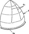
图16至18中的每一个都示出包括半球形盖子5A(可以等同于前面提到的第一盖子)的无线电波透镜天线设备。屏障9设置在盖子5A的表面上以用作防冰-雪-水装置。无线电波透镜天线设备包括半球形盖子5A以覆盖并保护透镜1。屏障9设置在半球形盖子5的外表面上。屏障9位于将天线元件3连接到透镜1的中心的直线的上方,并在横向延伸预定长度。Each of FIGS. 16 to 18 shows a radio wave lens antenna device including a
对应于天线元件3的盖子表面的部分处于无线电波朝向天线元件传播的区域中。因此,通过防止水流经该区域,能够减小无线电波被这种水引起的衰减。为达到该目标,屏障9设置在半球形盖子5A的外表面上以阻塞流水的路径。屏障9可以包括如图17(a)所示的凹槽9a、如图17(b)和17(c)所示的凸起9b,或者如图17(d)和17(e)所示的在半球形盖子5A的外表面内形成的台阶9c。每个屏障9具有预定宽度。A portion corresponding to the cover surface of the
如图18所示,优选屏障9面向天线元件3的部分位于高出地面的位置,并且屏障9朝向横向末端逐渐变低。这有效地将水引导到不影响无线电波接收的区域。As shown in Fig. 18, it is preferable that the portion of the
在图19的无线电波透镜天线设备中,屏障13设置在半球形第一盖子5的外表面上以防止水流向对应于天线元件3的盖子部分。以这种方式,不仅当反射板2被设置成垂直于地面而且当反射板2被设置成平行于地面时,屏障都是有效的。In the radio wave lens antenna device of FIG. 19 , a
图20示出的无线电波透镜天线设备包括图3的第二盖子和图16的屏障9。该无线电波透镜天线设备综合地获得了第二盖子6防止雨水和融雪聚集的效果以及屏障9防止水流到面向天线元件3的部分的效果。因此,该结构对于显著降低当下雨及雪融化时无线电波的衰减是有效的。The radio wave lens antenna device shown in FIG. 20 includes the second cover of FIG. 3 and the
拒水的盖子表面会是一种防止雨水和融雪聚集的防雪-冰-水装置的有效示例。当第一盖子5或第二盖子6(或12)经过拒水处理时,水以大角度与盖子形成接触。该拒水从而使水不聚集在盖子表面上。特别优选的是在具有大倾斜角度的第二盖子6(或12)上实施拒水处理,这是由于这种结构对于防止水聚集会是有效的。A water-repellent cover surface would be an effective example of a snow-ice-water protection against the accumulation of rainwater and snowmelt. When the
在图21中,在第一盖子5的顶部实施亲水处理以限定亲水部分10,并且在排除所述顶部之外的第一盖子5的上部倾斜表面上实施拒水处理以限定一个疏水部分11。当更靠近地面的表面经过拒水处理时,被排斥的水不流动并形成聚集在盖子上的水滴。这是起反作用的。因此,仅在顶部实施亲水处理以防止水聚集。In FIG. 21, a hydrophilic treatment is applied to the top of the
在图22显示出的示例中,由包括小疏水涂层的亲水涂层在第一盖子5的表面上形成涂层或所谓的“海岛结构”。在这种结构中,水被由疏水涂层形成的疏水部分11(岛部)排斥,并沿着亲水部分10(海洋部分)流动。这防止雨水和融化的冰雪聚集。优选疏水部分11是小的并且具有1至5mm的直径。而且,由于亲水部分10临时形成水膜,优选疏水部分11和亲水部分10的面积比使得疏水部分11的面积大于亲水部分10的面积。In the example shown in Fig. 22, a coating or a so-called "sea-island structure" is formed on the surface of the
可以在图17和18所示的屏障9上在水分散性能尤其应当增加以改善疏水性的部分实施拒水处理。Water-repellent treatment may be performed on the
通常通过应用拒水的或亲水涂层而实施拒水处理和亲水处理。然而,本发明不局限于这种方式,而是可以进行其它的表面变型处理。Water-repellent and hydrophilic treatments are typically performed by applying a water-repellent or hydrophilic coating. However, the invention is not limited in this way, but other surface modification treatments can be performed.
上述防冰-雪-水装置可以结合使用,例如,如图23至25所示。The above-described ice-snow-water protection devices may be used in combination, for example, as shown in FIGS. 23 to 25 .
现在将描述为检查本发明的效果而进行的实验。实验中准备了在表1中示出的说明书的无线电波透镜天线设备(示例和比较例)。图26所示的测量系统用于在雨或雪中每十分钟测量天线设备的信号接收灵敏度(C/N)。通常,当满足C/N<6时不能在TV显示器上产生图像。因此,检测满足C/N≥6的时间以获得相对于满足C/N<6的时间之比。结果显示在表1中。根据表1很明显的是,在应用本发明的示例中,出现无线电波干扰的时间(期间产生图像的时间较长)比对比示例短。因此,明显防冰-雪-水装置对于防止雨和雪降低信号接收灵敏度是有效的。Experiments conducted to examine the effects of the present invention will now be described. The radio wave lens antenna devices (example and comparative example) of the specification shown in Table 1 were prepared in the experiment. The measurement system shown in FIG. 26 is used to measure the signal reception sensitivity (C/N) of the antenna device every ten minutes in rain or snow. Generally, images cannot be produced on a TV display when C/N<6 is satisfied. Therefore, the time satisfying C/N≧6 is detected to obtain a ratio with respect to the time satisfying C/N<6. The results are shown in Table 1. It is apparent from Table 1 that in the example to which the present invention is applied, the time during which radio wave interference occurs (the time during which images are generated is longer) is shorter than in the comparative example. Therefore, it is clear that the anti-ice-snow-water device is effective in preventing rain and snow from degrading signal reception sensitivity.
[表1][Table 1]
Claims (19)
Applications Claiming Priority (1)
| Application Number | Priority Date | Filing Date | Title |
|---|---|---|---|
| PCT/JP2006/311419WO2007141850A1 (en) | 2006-06-07 | 2006-06-07 | Radio wave lens antenna device |
Publications (1)
| Publication Number | Publication Date |
|---|---|
| CN101461091Atrue CN101461091A (en) | 2009-06-17 |
Family
ID=38801122
Family Applications (1)
| Application Number | Title | Priority Date | Filing Date |
|---|---|---|---|
| CNA2006800548679APendingCN101461091A (en) | 2006-06-07 | 2006-06-07 | Radio wave lens antenna device |
Country Status (4)
| Country | Link |
|---|---|
| US (1) | US20100039339A1 (en) |
| EP (1) | EP2037531A1 (en) |
| CN (1) | CN101461091A (en) |
| WO (1) | WO2007141850A1 (en) |
Cited By (3)
| Publication number | Priority date | Publication date | Assignee | Title |
|---|---|---|---|---|
| WO2012163237A1 (en)* | 2011-05-27 | 2012-12-06 | 京信通信系统(中国)有限公司 | Broadband shaped antenna radome and microwave antenna |
| WO2022088645A1 (en)* | 2020-11-02 | 2022-05-05 | 上海玥煊科技有限公司 | Radar beacon and radar measurement system |
| CN114628895A (en)* | 2020-12-08 | 2022-06-14 | 安波福技术有限公司 | Cover plate supporting ultra-wide radar view field |
Families Citing this family (157)
| Publication number | Priority date | Publication date | Assignee | Title |
|---|---|---|---|---|
| JP5229915B2 (en)* | 2009-12-10 | 2013-07-03 | シャープ株式会社 | Millimeter wave receiver, millimeter wave receiver mounting structure, and millimeter wave transceiver |
| US8368552B2 (en) | 2009-12-22 | 2013-02-05 | At&T Intellectual Property I, L.P. | Manhole security device and methods thereof |
| US10009065B2 (en) | 2012-12-05 | 2018-06-26 | At&T Intellectual Property I, L.P. | Backhaul link for distributed antenna system |
| US9113347B2 (en) | 2012-12-05 | 2015-08-18 | At&T Intellectual Property I, Lp | Backhaul link for distributed antenna system |
| US9999038B2 (en) | 2013-05-31 | 2018-06-12 | At&T Intellectual Property I, L.P. | Remote distributed antenna system |
| US9525524B2 (en) | 2013-05-31 | 2016-12-20 | At&T Intellectual Property I, L.P. | Remote distributed antenna system |
| US8897697B1 (en) | 2013-11-06 | 2014-11-25 | At&T Intellectual Property I, Lp | Millimeter-wave surface-wave communications |
| US9209902B2 (en) | 2013-12-10 | 2015-12-08 | At&T Intellectual Property I, L.P. | Quasi-optical coupler |
| JP6315423B2 (en) | 2014-06-04 | 2018-04-25 | パナソニックIpマネジメント株式会社 | Radio apparatus and radio system |
| US9692101B2 (en) | 2014-08-26 | 2017-06-27 | At&T Intellectual Property I, L.P. | Guided wave couplers for coupling electromagnetic waves between a waveguide surface and a surface of a wire |
| US9768833B2 (en) | 2014-09-15 | 2017-09-19 | At&T Intellectual Property I, L.P. | Method and apparatus for sensing a condition in a transmission medium of electromagnetic waves |
| US10063280B2 (en) | 2014-09-17 | 2018-08-28 | At&T Intellectual Property I, L.P. | Monitoring and mitigating conditions in a communication network |
| US9615269B2 (en) | 2014-10-02 | 2017-04-04 | At&T Intellectual Property I, L.P. | Method and apparatus that provides fault tolerance in a communication network |
| US9685992B2 (en) | 2014-10-03 | 2017-06-20 | At&T Intellectual Property I, L.P. | Circuit panel network and methods thereof |
| US9503189B2 (en) | 2014-10-10 | 2016-11-22 | At&T Intellectual Property I, L.P. | Method and apparatus for arranging communication sessions in a communication system |
| US9762289B2 (en) | 2014-10-14 | 2017-09-12 | At&T Intellectual Property I, L.P. | Method and apparatus for transmitting or receiving signals in a transportation system |
| US9973299B2 (en) | 2014-10-14 | 2018-05-15 | At&T Intellectual Property I, L.P. | Method and apparatus for adjusting a mode of communication in a communication network |
| US9520945B2 (en) | 2014-10-21 | 2016-12-13 | At&T Intellectual Property I, L.P. | Apparatus for providing communication services and methods thereof |
| US9780834B2 (en) | 2014-10-21 | 2017-10-03 | At&T Intellectual Property I, L.P. | Method and apparatus for transmitting electromagnetic waves |
| US9627768B2 (en) | 2014-10-21 | 2017-04-18 | At&T Intellectual Property I, L.P. | Guided-wave transmission device with non-fundamental mode propagation and methods for use therewith |
| US9769020B2 (en) | 2014-10-21 | 2017-09-19 | At&T Intellectual Property I, L.P. | Method and apparatus for responding to events affecting communications in a communication network |
| US9653770B2 (en) | 2014-10-21 | 2017-05-16 | At&T Intellectual Property I, L.P. | Guided wave coupler, coupling module and methods for use therewith |
| US9577306B2 (en) | 2014-10-21 | 2017-02-21 | At&T Intellectual Property I, L.P. | Guided-wave transmission device and methods for use therewith |
| US9312919B1 (en) | 2014-10-21 | 2016-04-12 | At&T Intellectual Property I, Lp | Transmission device with impairment compensation and methods for use therewith |
| US9800327B2 (en) | 2014-11-20 | 2017-10-24 | At&T Intellectual Property I, L.P. | Apparatus for controlling operations of a communication device and methods thereof |
| US10340573B2 (en) | 2016-10-26 | 2019-07-02 | At&T Intellectual Property I, L.P. | Launcher with cylindrical coupling device and methods for use therewith |
| US9954287B2 (en) | 2014-11-20 | 2018-04-24 | At&T Intellectual Property I, L.P. | Apparatus for converting wireless signals and electromagnetic waves and methods thereof |
| US9654173B2 (en) | 2014-11-20 | 2017-05-16 | At&T Intellectual Property I, L.P. | Apparatus for powering a communication device and methods thereof |
| US9461706B1 (en) | 2015-07-31 | 2016-10-04 | At&T Intellectual Property I, Lp | Method and apparatus for exchanging communication signals |
| US9997819B2 (en) | 2015-06-09 | 2018-06-12 | At&T Intellectual Property I, L.P. | Transmission medium and method for facilitating propagation of electromagnetic waves via a core |
| US9544006B2 (en) | 2014-11-20 | 2017-01-10 | At&T Intellectual Property I, L.P. | Transmission device with mode division multiplexing and methods for use therewith |
| US9742462B2 (en) | 2014-12-04 | 2017-08-22 | At&T Intellectual Property I, L.P. | Transmission medium and communication interfaces and methods for use therewith |
| US10009067B2 (en) | 2014-12-04 | 2018-06-26 | At&T Intellectual Property I, L.P. | Method and apparatus for configuring a communication interface |
| US9680670B2 (en) | 2014-11-20 | 2017-06-13 | At&T Intellectual Property I, L.P. | Transmission device with channel equalization and control and methods for use therewith |
| US10243784B2 (en) | 2014-11-20 | 2019-03-26 | At&T Intellectual Property I, L.P. | System for generating topology information and methods thereof |
| US10144036B2 (en) | 2015-01-30 | 2018-12-04 | At&T Intellectual Property I, L.P. | Method and apparatus for mitigating interference affecting a propagation of electromagnetic waves guided by a transmission medium |
| US9876570B2 (en) | 2015-02-20 | 2018-01-23 | At&T Intellectual Property I, Lp | Guided-wave transmission device with non-fundamental mode propagation and methods for use therewith |
| US9749013B2 (en) | 2015-03-17 | 2017-08-29 | At&T Intellectual Property I, L.P. | Method and apparatus for reducing attenuation of electromagnetic waves guided by a transmission medium |
| US10224981B2 (en) | 2015-04-24 | 2019-03-05 | At&T Intellectual Property I, Lp | Passive electrical coupling device and methods for use therewith |
| US9705561B2 (en) | 2015-04-24 | 2017-07-11 | At&T Intellectual Property I, L.P. | Directional coupling device and methods for use therewith |
| US9793954B2 (en) | 2015-04-28 | 2017-10-17 | At&T Intellectual Property I, L.P. | Magnetic coupling device and methods for use therewith |
| US9948354B2 (en) | 2015-04-28 | 2018-04-17 | At&T Intellectual Property I, L.P. | Magnetic coupling device with reflective plate and methods for use therewith |
| US9871282B2 (en) | 2015-05-14 | 2018-01-16 | At&T Intellectual Property I, L.P. | At least one transmission medium having a dielectric surface that is covered at least in part by a second dielectric |
| US9748626B2 (en) | 2015-05-14 | 2017-08-29 | At&T Intellectual Property I, L.P. | Plurality of cables having different cross-sectional shapes which are bundled together to form a transmission medium |
| US9490869B1 (en) | 2015-05-14 | 2016-11-08 | At&T Intellectual Property I, L.P. | Transmission medium having multiple cores and methods for use therewith |
| US10650940B2 (en) | 2015-05-15 | 2020-05-12 | At&T Intellectual Property I, L.P. | Transmission medium having a conductive material and methods for use therewith |
| US9917341B2 (en) | 2015-05-27 | 2018-03-13 | At&T Intellectual Property I, L.P. | Apparatus and method for launching electromagnetic waves and for modifying radial dimensions of the propagating electromagnetic waves |
| US10103801B2 (en) | 2015-06-03 | 2018-10-16 | At&T Intellectual Property I, L.P. | Host node device and methods for use therewith |
| US10812174B2 (en) | 2015-06-03 | 2020-10-20 | At&T Intellectual Property I, L.P. | Client node device and methods for use therewith |
| US9912381B2 (en) | 2015-06-03 | 2018-03-06 | At&T Intellectual Property I, Lp | Network termination and methods for use therewith |
| US9866309B2 (en) | 2015-06-03 | 2018-01-09 | At&T Intellectual Property I, Lp | Host node device and methods for use therewith |
| US9913139B2 (en) | 2015-06-09 | 2018-03-06 | At&T Intellectual Property I, L.P. | Signal fingerprinting for authentication of communicating devices |
| US10142086B2 (en) | 2015-06-11 | 2018-11-27 | At&T Intellectual Property I, L.P. | Repeater and methods for use therewith |
| US9608692B2 (en) | 2015-06-11 | 2017-03-28 | At&T Intellectual Property I, L.P. | Repeater and methods for use therewith |
| US9820146B2 (en) | 2015-06-12 | 2017-11-14 | At&T Intellectual Property I, L.P. | Method and apparatus for authentication and identity management of communicating devices |
| US9667317B2 (en) | 2015-06-15 | 2017-05-30 | At&T Intellectual Property I, L.P. | Method and apparatus for providing security using network traffic adjustments |
| US9640850B2 (en) | 2015-06-25 | 2017-05-02 | At&T Intellectual Property I, L.P. | Methods and apparatus for inducing a non-fundamental wave mode on a transmission medium |
| US9509415B1 (en) | 2015-06-25 | 2016-11-29 | At&T Intellectual Property I, L.P. | Methods and apparatus for inducing a fundamental wave mode on a transmission medium |
| US9865911B2 (en) | 2015-06-25 | 2018-01-09 | At&T Intellectual Property I, L.P. | Waveguide system for slot radiating first electromagnetic waves that are combined into a non-fundamental wave mode second electromagnetic wave on a transmission medium |
| US9882257B2 (en) | 2015-07-14 | 2018-01-30 | At&T Intellectual Property I, L.P. | Method and apparatus for launching a wave mode that mitigates interference |
| US10148016B2 (en) | 2015-07-14 | 2018-12-04 | At&T Intellectual Property I, L.P. | Apparatus and methods for communicating utilizing an antenna array |
| US10044409B2 (en) | 2015-07-14 | 2018-08-07 | At&T Intellectual Property I, L.P. | Transmission medium and methods for use therewith |
| US10205655B2 (en) | 2015-07-14 | 2019-02-12 | At&T Intellectual Property I, L.P. | Apparatus and methods for communicating utilizing an antenna array and multiple communication paths |
| US10320586B2 (en) | 2015-07-14 | 2019-06-11 | At&T Intellectual Property I, L.P. | Apparatus and methods for generating non-interfering electromagnetic waves on an insulated transmission medium |
| US9628116B2 (en) | 2015-07-14 | 2017-04-18 | At&T Intellectual Property I, L.P. | Apparatus and methods for transmitting wireless signals |
| US9847566B2 (en) | 2015-07-14 | 2017-12-19 | At&T Intellectual Property I, L.P. | Method and apparatus for adjusting a field of a signal to mitigate interference |
| US10341142B2 (en) | 2015-07-14 | 2019-07-02 | At&T Intellectual Property I, L.P. | Apparatus and methods for generating non-interfering electromagnetic waves on an uninsulated conductor |
| US10170840B2 (en) | 2015-07-14 | 2019-01-01 | At&T Intellectual Property I, L.P. | Apparatus and methods for sending or receiving electromagnetic signals |
| US10033108B2 (en) | 2015-07-14 | 2018-07-24 | At&T Intellectual Property I, L.P. | Apparatus and methods for generating an electromagnetic wave having a wave mode that mitigates interference |
| US9722318B2 (en) | 2015-07-14 | 2017-08-01 | At&T Intellectual Property I, L.P. | Method and apparatus for coupling an antenna to a device |
| US9853342B2 (en) | 2015-07-14 | 2017-12-26 | At&T Intellectual Property I, L.P. | Dielectric transmission medium connector and methods for use therewith |
| US9836957B2 (en) | 2015-07-14 | 2017-12-05 | At&T Intellectual Property I, L.P. | Method and apparatus for communicating with premises equipment |
| US10033107B2 (en) | 2015-07-14 | 2018-07-24 | At&T Intellectual Property I, L.P. | Method and apparatus for coupling an antenna to a device |
| US9793951B2 (en) | 2015-07-15 | 2017-10-17 | At&T Intellectual Property I, L.P. | Method and apparatus for launching a wave mode that mitigates interference |
| US10090606B2 (en) | 2015-07-15 | 2018-10-02 | At&T Intellectual Property I, L.P. | Antenna system with dielectric array and methods for use therewith |
| US9608740B2 (en) | 2015-07-15 | 2017-03-28 | At&T Intellectual Property I, L.P. | Method and apparatus for launching a wave mode that mitigates interference |
| US9912027B2 (en) | 2015-07-23 | 2018-03-06 | At&T Intellectual Property I, L.P. | Method and apparatus for exchanging communication signals |
| US9871283B2 (en) | 2015-07-23 | 2018-01-16 | At&T Intellectual Property I, Lp | Transmission medium having a dielectric core comprised of plural members connected by a ball and socket configuration |
| US9948333B2 (en) | 2015-07-23 | 2018-04-17 | At&T Intellectual Property I, L.P. | Method and apparatus for wireless communications to mitigate interference |
| US9749053B2 (en) | 2015-07-23 | 2017-08-29 | At&T Intellectual Property I, L.P. | Node device, repeater and methods for use therewith |
| US10784670B2 (en) | 2015-07-23 | 2020-09-22 | At&T Intellectual Property I, L.P. | Antenna support for aligning an antenna |
| US9967173B2 (en) | 2015-07-31 | 2018-05-08 | At&T Intellectual Property I, L.P. | Method and apparatus for authentication and identity management of communicating devices |
| US9735833B2 (en) | 2015-07-31 | 2017-08-15 | At&T Intellectual Property I, L.P. | Method and apparatus for communications management in a neighborhood network |
| US10020587B2 (en) | 2015-07-31 | 2018-07-10 | At&T Intellectual Property I, L.P. | Radial antenna and methods for use therewith |
| US9904535B2 (en) | 2015-09-14 | 2018-02-27 | At&T Intellectual Property I, L.P. | Method and apparatus for distributing software |
| US10009063B2 (en) | 2015-09-16 | 2018-06-26 | At&T Intellectual Property I, L.P. | Method and apparatus for use with a radio distributed antenna system having an out-of-band reference signal |
| US10079661B2 (en) | 2015-09-16 | 2018-09-18 | At&T Intellectual Property I, L.P. | Method and apparatus for use with a radio distributed antenna system having a clock reference |
| US10009901B2 (en) | 2015-09-16 | 2018-06-26 | At&T Intellectual Property I, L.P. | Method, apparatus, and computer-readable storage medium for managing utilization of wireless resources between base stations |
| US10136434B2 (en) | 2015-09-16 | 2018-11-20 | At&T Intellectual Property I, L.P. | Method and apparatus for use with a radio distributed antenna system having an ultra-wideband control channel |
| US9769128B2 (en) | 2015-09-28 | 2017-09-19 | At&T Intellectual Property I, L.P. | Method and apparatus for encryption of communications over a network |
| US9729197B2 (en) | 2015-10-01 | 2017-08-08 | At&T Intellectual Property I, L.P. | Method and apparatus for communicating network management traffic over a network |
| US9882277B2 (en) | 2015-10-02 | 2018-01-30 | At&T Intellectual Property I, Lp | Communication device and antenna assembly with actuated gimbal mount |
| US9876264B2 (en) | 2015-10-02 | 2018-01-23 | At&T Intellectual Property I, Lp | Communication system, guided wave switch and methods for use therewith |
| US10355367B2 (en) | 2015-10-16 | 2019-07-16 | At&T Intellectual Property I, L.P. | Antenna structure for exchanging wireless signals |
| US10665942B2 (en) | 2015-10-16 | 2020-05-26 | At&T Intellectual Property I, L.P. | Method and apparatus for adjusting wireless communications |
| US9912419B1 (en) | 2016-08-24 | 2018-03-06 | At&T Intellectual Property I, L.P. | Method and apparatus for managing a fault in a distributed antenna system |
| US9860075B1 (en) | 2016-08-26 | 2018-01-02 | At&T Intellectual Property I, L.P. | Method and communication node for broadband distribution |
| US10291311B2 (en) | 2016-09-09 | 2019-05-14 | At&T Intellectual Property I, L.P. | Method and apparatus for mitigating a fault in a distributed antenna system |
| US11032819B2 (en) | 2016-09-15 | 2021-06-08 | At&T Intellectual Property I, L.P. | Method and apparatus for use with a radio distributed antenna system having a control channel reference signal |
| US10490907B2 (en)* | 2016-09-27 | 2019-11-26 | Google Llc | Suppression of surface waves in printed circuit board-based phased-array antennas |
| US10135146B2 (en) | 2016-10-18 | 2018-11-20 | At&T Intellectual Property I, L.P. | Apparatus and methods for launching guided waves via circuits |
| US10135147B2 (en) | 2016-10-18 | 2018-11-20 | At&T Intellectual Property I, L.P. | Apparatus and methods for launching guided waves via an antenna |
| US10340600B2 (en) | 2016-10-18 | 2019-07-02 | At&T Intellectual Property I, L.P. | Apparatus and methods for launching guided waves via plural waveguide systems |
| US10374316B2 (en) | 2016-10-21 | 2019-08-06 | At&T Intellectual Property I, L.P. | System and dielectric antenna with non-uniform dielectric |
| US9991580B2 (en) | 2016-10-21 | 2018-06-05 | At&T Intellectual Property I, L.P. | Launcher and coupling system for guided wave mode cancellation |
| US9876605B1 (en) | 2016-10-21 | 2018-01-23 | At&T Intellectual Property I, L.P. | Launcher and coupling system to support desired guided wave mode |
| US10811767B2 (en) | 2016-10-21 | 2020-10-20 | At&T Intellectual Property I, L.P. | System and dielectric antenna with convex dielectric radome |
| US10312567B2 (en) | 2016-10-26 | 2019-06-04 | At&T Intellectual Property I, L.P. | Launcher with planar strip antenna and methods for use therewith |
| US10498044B2 (en) | 2016-11-03 | 2019-12-03 | At&T Intellectual Property I, L.P. | Apparatus for configuring a surface of an antenna |
| US10225025B2 (en) | 2016-11-03 | 2019-03-05 | At&T Intellectual Property I, L.P. | Method and apparatus for detecting a fault in a communication system |
| US10291334B2 (en) | 2016-11-03 | 2019-05-14 | At&T Intellectual Property I, L.P. | System for detecting a fault in a communication system |
| US10224634B2 (en) | 2016-11-03 | 2019-03-05 | At&T Intellectual Property I, L.P. | Methods and apparatus for adjusting an operational characteristic of an antenna |
| US10340601B2 (en) | 2016-11-23 | 2019-07-02 | At&T Intellectual Property I, L.P. | Multi-antenna system and methods for use therewith |
| US10535928B2 (en) | 2016-11-23 | 2020-01-14 | At&T Intellectual Property I, L.P. | Antenna system and methods for use therewith |
| US10340603B2 (en) | 2016-11-23 | 2019-07-02 | At&T Intellectual Property I, L.P. | Antenna system having shielded structural configurations for assembly |
| US10090594B2 (en) | 2016-11-23 | 2018-10-02 | At&T Intellectual Property I, L.P. | Antenna system having structural configurations for assembly |
| US10178445B2 (en) | 2016-11-23 | 2019-01-08 | At&T Intellectual Property I, L.P. | Methods, devices, and systems for load balancing between a plurality of waveguides |
| US10361489B2 (en) | 2016-12-01 | 2019-07-23 | At&T Intellectual Property I, L.P. | Dielectric dish antenna system and methods for use therewith |
| US10305190B2 (en) | 2016-12-01 | 2019-05-28 | At&T Intellectual Property I, L.P. | Reflecting dielectric antenna system and methods for use therewith |
| US10135145B2 (en) | 2016-12-06 | 2018-11-20 | At&T Intellectual Property I, L.P. | Apparatus and methods for generating an electromagnetic wave along a transmission medium |
| US10755542B2 (en) | 2016-12-06 | 2020-08-25 | At&T Intellectual Property I, L.P. | Method and apparatus for surveillance via guided wave communication |
| US10637149B2 (en) | 2016-12-06 | 2020-04-28 | At&T Intellectual Property I, L.P. | Injection molded dielectric antenna and methods for use therewith |
| US10020844B2 (en) | 2016-12-06 | 2018-07-10 | T&T Intellectual Property I, L.P. | Method and apparatus for broadcast communication via guided waves |
| US10819035B2 (en) | 2016-12-06 | 2020-10-27 | At&T Intellectual Property I, L.P. | Launcher with helical antenna and methods for use therewith |
| US9927517B1 (en) | 2016-12-06 | 2018-03-27 | At&T Intellectual Property I, L.P. | Apparatus and methods for sensing rainfall |
| US10727599B2 (en) | 2016-12-06 | 2020-07-28 | At&T Intellectual Property I, L.P. | Launcher with slot antenna and methods for use therewith |
| US10694379B2 (en) | 2016-12-06 | 2020-06-23 | At&T Intellectual Property I, L.P. | Waveguide system with device-based authentication and methods for use therewith |
| US10326494B2 (en) | 2016-12-06 | 2019-06-18 | At&T Intellectual Property I, L.P. | Apparatus for measurement de-embedding and methods for use therewith |
| US10382976B2 (en) | 2016-12-06 | 2019-08-13 | At&T Intellectual Property I, L.P. | Method and apparatus for managing wireless communications based on communication paths and network device positions |
| US10439675B2 (en) | 2016-12-06 | 2019-10-08 | At&T Intellectual Property I, L.P. | Method and apparatus for repeating guided wave communication signals |
| US10243270B2 (en) | 2016-12-07 | 2019-03-26 | At&T Intellectual Property I, L.P. | Beam adaptive multi-feed dielectric antenna system and methods for use therewith |
| US10389029B2 (en) | 2016-12-07 | 2019-08-20 | At&T Intellectual Property I, L.P. | Multi-feed dielectric antenna system with core selection and methods for use therewith |
| US9893795B1 (en) | 2016-12-07 | 2018-02-13 | At&T Intellectual Property I, Lp | Method and repeater for broadband distribution |
| US10359749B2 (en) | 2016-12-07 | 2019-07-23 | At&T Intellectual Property I, L.P. | Method and apparatus for utilities management via guided wave communication |
| US10547348B2 (en) | 2016-12-07 | 2020-01-28 | At&T Intellectual Property I, L.P. | Method and apparatus for switching transmission mediums in a communication system |
| US10139820B2 (en) | 2016-12-07 | 2018-11-27 | At&T Intellectual Property I, L.P. | Method and apparatus for deploying equipment of a communication system |
| US10027397B2 (en) | 2016-12-07 | 2018-07-17 | At&T Intellectual Property I, L.P. | Distributed antenna system and methods for use therewith |
| US10168695B2 (en) | 2016-12-07 | 2019-01-01 | At&T Intellectual Property I, L.P. | Method and apparatus for controlling an unmanned aircraft |
| US10446936B2 (en) | 2016-12-07 | 2019-10-15 | At&T Intellectual Property I, L.P. | Multi-feed dielectric antenna system and methods for use therewith |
| US10530505B2 (en) | 2016-12-08 | 2020-01-07 | At&T Intellectual Property I, L.P. | Apparatus and methods for launching electromagnetic waves along a transmission medium |
| US10777873B2 (en) | 2016-12-08 | 2020-09-15 | At&T Intellectual Property I, L.P. | Method and apparatus for mounting network devices |
| US10601494B2 (en) | 2016-12-08 | 2020-03-24 | At&T Intellectual Property I, L.P. | Dual-band communication device and method for use therewith |
| US10411356B2 (en) | 2016-12-08 | 2019-09-10 | At&T Intellectual Property I, L.P. | Apparatus and methods for selectively targeting communication devices with an antenna array |
| US9911020B1 (en) | 2016-12-08 | 2018-03-06 | At&T Intellectual Property I, L.P. | Method and apparatus for tracking via a radio frequency identification device |
| US10326689B2 (en) | 2016-12-08 | 2019-06-18 | At&T Intellectual Property I, L.P. | Method and system for providing alternative communication paths |
| US10069535B2 (en) | 2016-12-08 | 2018-09-04 | At&T Intellectual Property I, L.P. | Apparatus and methods for launching electromagnetic waves having a certain electric field structure |
| US10916969B2 (en) | 2016-12-08 | 2021-02-09 | At&T Intellectual Property I, L.P. | Method and apparatus for providing power using an inductive coupling |
| US10103422B2 (en) | 2016-12-08 | 2018-10-16 | At&T Intellectual Property I, L.P. | Method and apparatus for mounting network devices |
| US9998870B1 (en) | 2016-12-08 | 2018-06-12 | At&T Intellectual Property I, L.P. | Method and apparatus for proximity sensing |
| US10389037B2 (en) | 2016-12-08 | 2019-08-20 | At&T Intellectual Property I, L.P. | Apparatus and methods for selecting sections of an antenna array and use therewith |
| US10938108B2 (en) | 2016-12-08 | 2021-03-02 | At&T Intellectual Property I, L.P. | Frequency selective multi-feed dielectric antenna system and methods for use therewith |
| US9838896B1 (en) | 2016-12-09 | 2017-12-05 | At&T Intellectual Property I, L.P. | Method and apparatus for assessing network coverage |
| US10264586B2 (en) | 2016-12-09 | 2019-04-16 | At&T Mobility Ii Llc | Cloud-based packet controller and methods for use therewith |
| US10340983B2 (en) | 2016-12-09 | 2019-07-02 | At&T Intellectual Property I, L.P. | Method and apparatus for surveying remote sites via guided wave communications |
| US9973940B1 (en) | 2017-02-27 | 2018-05-15 | At&T Intellectual Property I, L.P. | Apparatus and methods for dynamic impedance matching of a guided wave launcher |
| US10298293B2 (en) | 2017-03-13 | 2019-05-21 | At&T Intellectual Property I, L.P. | Apparatus of communication utilizing wireless network devices |
| KR102531003B1 (en)* | 2017-12-19 | 2023-05-10 | 삼성전자 주식회사 | Beam forming antenna module including lens |
Family Cites Families (16)
| Publication number | Priority date | Publication date | Assignee | Title |
|---|---|---|---|---|
| JPS50116259A (en) | 1974-02-26 | 1975-09-11 | ||
| US5781163A (en)* | 1995-08-28 | 1998-07-14 | Datron/Transco, Inc. | Low profile hemispherical lens antenna array on a ground plane |
| JP3117634B2 (en)* | 1995-12-28 | 2000-12-18 | 三菱電機株式会社 | Radome with water film prevention mechanism |
| JPH1046526A (en)* | 1996-05-31 | 1998-02-17 | Toto Ltd | Antifouling noise insulating wall |
| JPH1168427A (en)* | 1997-08-08 | 1999-03-09 | Nobue Mizukoshi | Antenna and antenna protecting cover |
| JPH1188028A (en)* | 1997-09-12 | 1999-03-30 | Matsushita Electric Works Ltd | Antenna unit |
| JPH1197916A (en)* | 1997-09-16 | 1999-04-09 | Wataru Osouda | Rain excluding equipment attached to converter of parabolic antenna |
| JP3616267B2 (en) | 1998-12-18 | 2005-02-02 | 株式会社東芝 | Antenna device |
| JP3742303B2 (en) | 2001-02-01 | 2006-02-01 | 株式会社東芝 | Lens antenna device |
| JP2002335112A (en)* | 2001-05-09 | 2002-11-22 | Toshiba Corp | Antenna snow prevention structure of wireless device |
| US6462717B1 (en)* | 2001-08-10 | 2002-10-08 | Caly Corporation | Enclosure for microwave radio transceiver with integral refractive antenna |
| JP3613281B2 (en) | 2001-09-28 | 2005-01-26 | 住友電気工業株式会社 | Radio wave lens antenna device |
| JP2004289736A (en)* | 2003-03-25 | 2004-10-14 | Nippon Dengyo Kosaku Co Ltd | Flat antenna device |
| JP3945491B2 (en)* | 2003-04-02 | 2007-07-18 | 住友電気工業株式会社 | Radio wave lens antenna device |
| JP2004320283A (en)* | 2003-04-15 | 2004-11-11 | Ueda Japan Radio Co Ltd | Antenna system with radome, and radome for preventing snow accretion/ice accretion |
| JP4109666B2 (en)* | 2004-11-24 | 2008-07-02 | 住友電気工業株式会社 | Radio wave lens antenna device |
- 2006
- 2006-06-07WOPCT/JP2006/311419patent/WO2007141850A1/enactiveApplication Filing
- 2006-06-07EPEP06757126Apatent/EP2037531A1/ennot_activeWithdrawn
- 2006-06-07USUS12/303,654patent/US20100039339A1/ennot_activeAbandoned
- 2006-06-07CNCNA2006800548679Apatent/CN101461091A/enactivePending
Cited By (3)
| Publication number | Priority date | Publication date | Assignee | Title |
|---|---|---|---|---|
| WO2012163237A1 (en)* | 2011-05-27 | 2012-12-06 | 京信通信系统(中国)有限公司 | Broadband shaped antenna radome and microwave antenna |
| WO2022088645A1 (en)* | 2020-11-02 | 2022-05-05 | 上海玥煊科技有限公司 | Radar beacon and radar measurement system |
| CN114628895A (en)* | 2020-12-08 | 2022-06-14 | 安波福技术有限公司 | Cover plate supporting ultra-wide radar view field |
Also Published As
| Publication number | Publication date |
|---|---|
| EP2037531A1 (en) | 2009-03-18 |
| US20100039339A1 (en) | 2010-02-18 |
| WO2007141850A1 (en) | 2007-12-13 |
Similar Documents
| Publication | Publication Date | Title |
|---|---|---|
| CN101461091A (en) | Radio wave lens antenna device | |
| US20050225495A1 (en) | Antenna systems for reliable satellite television reception in moisture conditions | |
| US6937184B2 (en) | Millimeter wave radar | |
| CN101098050B (en) | Radio wave lens antenna device | |
| US5426443A (en) | Dielectric-supported reflector system | |
| JP7108930B2 (en) | Antenna device and in-vehicle light device | |
| AU719718B2 (en) | Device for covering the aperture of an antenna | |
| CN102428606A (en) | Radome for tracking antenna | |
| US12010410B2 (en) | Monitoring camera | |
| JP4109666B2 (en) | Radio wave lens antenna device | |
| JP2008086049A (en) | Radio wave lens antenna device | |
| JPWO2006129365A1 (en) | Radio wave lens antenna device | |
| JP3117634B2 (en) | Radome with water film prevention mechanism | |
| US8179335B2 (en) | Stepped radome and antenna having a stepped radome | |
| EP3227958B1 (en) | Antenna radome with absorbers | |
| JP7258217B2 (en) | millimeter wave radar | |
| US12362453B2 (en) | Solar mitigation solutions for electronic equipment | |
| JP2005203978A (en) | Antenna radome | |
| JP3816027B2 (en) | Antenna radome with excellent water film adhesion prevention | |
| JP2005257352A (en) | Wrong detection prevention structure for sensor, and sensor | |
| JP2007060130A (en) | Radome | |
| JP7208102B2 (en) | antenna device | |
| JPH07221527A (en) | Antenna system | |
| CN220914571U (en) | Phased array radome of quick drainage | |
| JP2003078325A (en) | Antenna cover and antenna |
Legal Events
| Date | Code | Title | Description |
|---|---|---|---|
| C06 | Publication | ||
| PB01 | Publication | ||
| C10 | Entry into substantive examination | ||
| SE01 | Entry into force of request for substantive examination | ||
| ASS | Succession or assignment of patent right | Owner name:SUMITOMO ELECTRIC INDUSTRIES CO., LTD. Free format text:FORMER OWNER: SEI COMPOSITE PRODUCTS CO., LTD. Effective date:20091120 | |
| C41 | Transfer of patent application or patent right or utility model | ||
| TA01 | Transfer of patent application right | Effective date of registration:20091120 Address after:Japan Osaka Applicant after:Sumitomo Electric Industries Ltd Co-applicant after:Sky Perfect Jsat Corp. Address before:Osaka, Japan Applicant before:SEI composite product Limited by Share Ltd Co-applicant before:Sky Perfect Jsat Corp. | |
| C02 | Deemed withdrawal of patent application after publication (patent law 2001) | ||
| WD01 | Invention patent application deemed withdrawn after publication | Open date:20090617 |