CN101460322B - Tire risk judging device of wheel assembly for vehicle - Google Patents
Tire risk judging device of wheel assembly for vehicleDownload PDFInfo
- Publication number
- CN101460322B CN101460322BCN2007800203377ACN200780020337ACN101460322BCN 101460322 BCN101460322 BCN 101460322BCN 2007800203377 ACN2007800203377 ACN 2007800203377ACN 200780020337 ACN200780020337 ACN 200780020337ACN 101460322 BCN101460322 BCN 101460322B
- Authority
- CN
- China
- Prior art keywords
- tire
- air
- risk
- specific position
- air pressure
- Prior art date
- Legal status (The legal status is an assumption and is not a legal conclusion. Google has not performed a legal analysis and makes no representation as to the accuracy of the status listed.)
- Expired - Fee Related
Links
Images

Classifications
- B—PERFORMING OPERATIONS; TRANSPORTING
- B60—VEHICLES IN GENERAL
- B60C—VEHICLE TYRES; TYRE INFLATION; TYRE CHANGING; CONNECTING VALVES TO INFLATABLE ELASTIC BODIES IN GENERAL; DEVICES OR ARRANGEMENTS RELATED TO TYRES
- B60C23/00—Devices for measuring, signalling, controlling, or distributing tyre pressure or temperature, specially adapted for mounting on vehicles; Arrangement of tyre inflating devices on vehicles, e.g. of pumps or of tanks; Tyre cooling arrangements
- B60C23/10—Arrangement of tyre-inflating pumps mounted on vehicles
- B60C23/12—Arrangement of tyre-inflating pumps mounted on vehicles operated by a running wheel
- B60C23/127—Arrangement of tyre-inflating pumps mounted on vehicles operated by a running wheel the pumps being mounted on the hubs
- B—PERFORMING OPERATIONS; TRANSPORTING
- B60—VEHICLES IN GENERAL
- B60C—VEHICLE TYRES; TYRE INFLATION; TYRE CHANGING; CONNECTING VALVES TO INFLATABLE ELASTIC BODIES IN GENERAL; DEVICES OR ARRANGEMENTS RELATED TO TYRES
- B60C23/00—Devices for measuring, signalling, controlling, or distributing tyre pressure or temperature, specially adapted for mounting on vehicles; Arrangement of tyre inflating devices on vehicles, e.g. of pumps or of tanks; Tyre cooling arrangements
- B60C23/10—Arrangement of tyre-inflating pumps mounted on vehicles
- B60C23/12—Arrangement of tyre-inflating pumps mounted on vehicles operated by a running wheel
- B60C23/137—Arrangement of tyre-inflating pumps mounted on vehicles operated by a running wheel comprising cam driven pistons
Landscapes
- Engineering & Computer Science (AREA)
- Mechanical Engineering (AREA)
- Measuring Fluid Pressure (AREA)
Abstract
Translated fromChinese
Description
Translated fromChinese技术领域technical field
本发明涉及用于车辆的车轮组件的轮胎危险判定设备。更具体而言,本发明涉及能够在车辆从当前位置行驶到特定位置时判定特定位置处的轮胎危险(会导致轮胎严重损坏的危险)的轮胎危险判定设备。The present invention relates to a tire risk judging device for a wheel assembly of a vehicle. More specifically, the present invention relates to a tire risk judging apparatus capable of judging a tire risk (a risk of causing severe tire damage) at a specific position when a vehicle travels from the current position to the specific position.
背景技术Background technique
例如在日本实用新型专利申请号Hei 4-50162(以下称为专利文献1)中揭示了在轮胎危险判定结果为“存在危险”时向驾乘者发出警报的用于车辆的轮胎组件的设备。For example, Japanese Utility Model Patent Application No. Hei 4-50162 (hereinafter referred to as Patent Document 1) discloses a device for a tire assembly of a vehicle that alerts the occupant when the tire risk determination result is "dangerous".
在专利文献1中揭示的轮胎气压控制器包括气流速率检测装置,其用于对从包含气泵的气压源经由截止阀向车轮组件的轮胎气腔供应的气流速率进行检测以输出与该气流速率相对应的信号;压力检测器,其检测轮胎气腔的气压以输出与该气压相对应的信号;空气泄漏警告装置,其用于基于气流速率检测装置的气流速率检测信号,在空气泄漏等于或大于与爆胎相对应的预定量时发出警告;以及控制器,其在从压力检测器输出表示气压降低的信号时打开截止阀直至从压力检测器输出表示气压返回至正常值的信号,并在运转开始的早期(在机动车的发动机起动时)停止发出警报达预定时间。The tire air pressure controller disclosed in
在专利文献1中描述的气压控制器中,当因为诸如爆胎的大量空气泄露导致轮胎气腔的气压降低时,从气压源向车轮组件的轮胎气腔供应的气流速率等于或大于预定值。空气泄漏警告装置基于气流速率检测装置的气流速率检测信号而发出警告。当因长时间处于小量漏气状态而导致轮胎气腔的气压降低时,在起动轮胎气压控制器时,气流速率增大从而发出警告。与机动车发动机起动时的情况类似,轮胎气压控制器在轮胎气压控制器的运转开始的早期,在预定时间内停止发出警告。In the air pressure controller described in
在专利文献1中描述的构造中,除了轮胎气压控制器的运转开始的早期阶段之外,当从气压源向车轮组件的轮胎气腔供应的气流速率等于或大于预定值时,空气泄漏警告装置基于气流速率检测装置的气流速率检测信号而发出警告。尽管存在导致轮胎极大损坏的危险(轮胎危险),但当轮胎的损坏较小并且从气压源向车轮组件的轮胎气腔供应的气流速率小于预定值时,空气泄漏警告装置就不会发出警告,由此不能将轮胎危险告知驾乘者。In the configuration described in
可通过将预定值设定的较小来解决上述问题。在进行设定时,当需要立即修理轮胎或者当无需立即修理轮胎时,空气泄漏警告装置均在从气压源向车轮组件的轮胎气腔供应的气流速率等于或大于预定值时发出警告。即使在空气泄漏警告装置发出警告时无需立即修理轮胎,也会因空气泄漏警告装置的警告而需要立即对轮胎进行修理。The above-mentioned problem can be solved by setting the predetermined value smaller. When set, the air leak warning device issues a warning when the airflow rate supplied from the air pressure source to the tire air chamber of the wheel assembly is equal to or greater than a predetermined value, when immediate tire repair is required or when immediate tire repair is not required. Even if the tire does not need to be repaired immediately when the air leak warning device warns, the tire may need to be repaired immediately due to the warning of the air leak warning device.
发明内容Contents of the invention
为了解决以上问题完成了本发明。根据本发明的一种用于车辆的车轮组件的轮胎危险判定设备包括:压力传感器,其对所述车辆的所述车轮组件的轮胎气腔的气压进行检测;气压产生设备,其能够向所述轮胎气腔供应增压空气;供应气流速率计算装置,其用于在所述车辆在具体路径上从当前位置行驶到特定位置时对从所述气压产生设备向所述轮胎气腔供应的供应气流速率进行计算;泄漏气流速率计算装置,其用于在所述车辆在所述具体路径上从所述当前位置行驶到所述特定位置时对从所述轮胎气腔泄漏的泄漏气流速率进行计算;轮胎气压计算装置,其用于根据由所述压力传感器所检测的所述轮胎气腔在所述当前位置的气压、由所述供应气流速率计算装置所计算的所述供应气流速率、以及由所述泄漏气流速率计算装置所计算的所述泄漏气流速率来对所述轮胎气腔在所述特定位置的气压进行计算;以及特定位置轮胎危险判定装置,其用于根据由所述轮胎气压计算装置所计算的所述轮胎气腔在所述特定位置的气压来对在所述特定位置的轮胎危险进行判定。The present invention has been accomplished in order to solve the above problems. A tire risk judging device for a wheel assembly of a vehicle according to the present invention includes: a pressure sensor, which detects the air pressure of the tire air cavity of the wheel assembly of the vehicle; a tire air chamber supply pressurized air; supply airflow rate calculating means for evaluating the supply airflow supplied from the air pressure generating device to the tire air chamber when the vehicle travels on a specific route from a current position to a specific position rate calculation; leakage airflow rate calculation means, which is used to calculate the leakage airflow rate leaked from the tire air cavity when the vehicle travels from the current position to the specific position on the specific route; tire air pressure calculation means for calculating the supply air flow rate calculated by the supply air flow rate calculation means based on the air pressure of the tire air cavity at the current position detected by the pressure sensor, and by the The air pressure of the tire air cavity at the specific position is calculated based on the leakage air flow rate calculated by the leakage air flow rate calculation device; The calculated air pressure of the tire air cavity at the specific position is used to determine the tire risk at the specific position.
在根据本发明的用于车辆的车轮组件的轮胎危险判定设备中,供应气流速率计算装置在所述车辆在具体路径上从当前位置行驶到特定位置时对从所述气压产生设备向所述轮胎气腔供应的供应气流速率进行计算,而泄漏气流速率计算装置在所述车辆在所述具体路径上从所述当前位置行驶到所述特定位置时对从所述轮胎气腔泄漏的泄漏气流速率进行计算。轮胎气压计算装置根据由所述压力传感器所检测的所述轮胎气腔在所述当前位置的气压、由所述供应气流速率计算装置所计算的所述供应气流速率、以及由所述泄漏气流速率计算装置所计算的所述泄漏气流速率来对所述轮胎气腔在所述特定位置的气压进行计算,而特定位置轮胎危险判定装置根据由所述轮胎气压计算装置所计算的所述轮胎气腔在所述特定位置的气压来对在所述特定位置的轮胎危险进行判定。In the tire risk judging device for a wheel assembly for a vehicle according to the present invention, the supply air flow rate calculating means is for the air pressure generating device from the air pressure generating device to the tire when the vehicle travels from a current position to a specific position on a specific route. The supply air flow rate supplied by the air cavity is calculated, and the leakage air flow rate calculation means calculates the leakage air flow rate from the air cavity of the tire when the vehicle travels on the specific route from the current position to the specific position Calculation. The tire air pressure calculation means is based on the air pressure of the tire air cavity at the current position detected by the pressure sensor, the supply air flow rate calculated by the supply air flow rate calculation means, and the leakage air flow rate The air pressure of the tire air cavity at the specific position is calculated based on the leakage air flow rate calculated by the calculation device, and the specific position tire risk determination device calculates the air pressure of the tire air cavity calculated by the tire air pressure calculation device The air pressure at the specific position is used to determine the tire risk at the specific position.
根据特定位置轮胎危险判定装置的判定结果,可在判定出在特定位置的轮胎危险。根据“在特定位置存在轮胎危险”的判定结果,能够告知在车辆从当前位置到达特定位置之前需要对轮胎立即进行修理。根据“在特定位置不存在轮胎危险”的判定结果,能够告知在车辆从当前位置到达特定位置之前无需对轮胎进行修理。可以在极佳的时机执行避免轮胎危险所需的轮胎修理。According to the determination result of the specific position tire risk determination device, the tire risk at the specific position can be determined. According to the determination result of "there is a tire danger at a specific position", it can be notified that the tire needs to be repaired immediately before the vehicle reaches the specific position from the current position. Based on the determination result of "there is no tire danger at the specific position", it can be informed that the tire does not need to be repaired until the vehicle reaches the specific position from the current position. The tire repairs needed to avoid tire hazards can be performed at an excellent time.
本发明还可实施为使得:用于车辆的车轮组件的轮胎危险判定设备可包括当前位置轮胎危险判定装置,其根据由所述压力传感器所检测的所述轮胎气腔在所述当前位置的气压来对在所述当前位置的轮胎危险进行判定。在此情况下,根据特定位置轮胎危险判定装置的判定结果,可以判定特定位置的轮胎危险,而根据当前位置轮胎危险判定装置的判定结果,可以判定当前位置的轮胎危险。根据“在特定位置存在轮胎危险”以及“在当前位置存在轮胎危险”的判定结果,能够告知需要在当前位置对轮胎立即进行修理。The present invention may also be implemented such that the tire risk judging apparatus for a wheel assembly of a vehicle may include a current position tire risk judging device that detects the air pressure of the tire air cavity at the current position based on the air pressure of the tire air cavity detected by the pressure sensor. to determine the tire risk at the current location. In this case, the tire risk at the specific position can be determined based on the determination result of the specific position tire risk determination device, and the tire risk at the current position can be determined based on the determination result of the current position tire risk determination device. Based on the determination results of "a tire is dangerous at a specific location" and "a tire is dangerous at a current location", it is possible to notify that the tire needs to be repaired immediately at the current location.
根据“在特定位置不存在轮胎危险”以及“在当前位置不存在轮胎危险”的判定结果,能够告知无需修理轮胎。根据“在特定位置存在轮胎危险”以及“在当前位置不存在轮胎危险”的判定结果,能够告知在车辆从当前位置到达特定位置时需要修理轮胎。根据“在特定位置不存在轮胎危险”以及“在当前位置存在轮胎危险”的判定结果,能够告知需要修理轮胎以及在车辆从当前位置到达特定位置之前无需修理轮胎。Based on the determination results of "there is no tire danger at the specific position" and "there is no tire danger at the current position", it can be notified that the tire does not need to be repaired. Based on the determination results of "there is a tire hazard at the specific location" and "there is no tire hazard at the current location", it can be notified that the tire needs to be repaired when the vehicle reaches the specific location from the current location. Based on the determination results of "there is no tire danger at the specific position" and "there is a tire danger at the current position", it is possible to notify that the tire needs to be repaired and that it is unnecessary to repair the tire until the vehicle reaches the specific position from the current position.
本发明也可实施为使得:用于车辆的车轮组件的轮胎危险判定设备可包括特定位置轮胎危险告知装置,其能够将由所述特定位置轮胎危险判定装置所判定的在所述特定位置的轮胎危险告知驾乘者。用于车辆的车轮组件的轮胎危险判定设备还可包括当前位置轮胎危险告知装置,其能够将由所述当前位置轮胎危险判定装置所判定的在所述当前位置的轮胎危险告知驾乘者。在这些情况下,各个告知装置可将轮胎危险精确地告知驾乘者。The present invention may also be implemented such that the tire risk judging device for a wheel assembly of a vehicle may include a specific position tire risk notifying device capable of reporting the tire risk at the specific position determined by the specific position tire risk judging device Inform the driver and passengers. The tire risk judging apparatus for a wheel assembly of a vehicle may further include a current position tire risk notifying means capable of notifying a driver and an occupant of the tire risk at the current position determined by the current position tire risk judging means. In these cases, individual notification devices can precisely inform the occupant of the tire danger.
本发明还可实施为使得:可通过所述车轮组件的旋转来驱动所述气压产生设备。在此情况下,当车轮组件停止时并不驱动气压产生设备。可以根据轮胎气腔的气压降低来以高精度计算来自轮胎气腔的泄漏气流速率。The present invention can also be implemented such that the air pressure generating device can be driven by rotation of the wheel assembly. In this case, the air pressure generating device is not driven when the wheel assembly is stopped. The leakage airflow rate from the tire air cavity can be calculated with high precision from the decrease in air pressure of the tire air cavity.
本发明还可实施为使得:用于车辆的车轮组件的轮胎危险判定设备可包括轮胎负载计算装置,其用于在所述车辆在所述具体路径上从所述当前位置行驶到所述特定位置时对施加在所述车轮组件的所述轮胎上的负载进行计算;以及轮胎危险修正装置,其用于根据由所述轮胎负载计算装置所计算的所述负载来对由所述特定位置轮胎危险判定装置所判定的所述轮胎危险进行修正。在该情况下,可以精确判定特定位置处的轮胎危险。可以根据具体路径上直路或弯路的比例(直路或弯路的总距离/具体路径的总距离)以及车辆的总重量来计算在轮胎上施加的负载。可根据从已知的车载导航设备获得的道路数据来计算直路或弯路的比例。可根据对车辆的有效负载及车体重量进行检测的负载传感器的输出来计算车辆的总重量。The present invention may also be implemented such that the tire risk judging apparatus for a wheel assembly of a vehicle may include tire load calculation means for driving from the current position to the specific position when the vehicle is traveling on the specific route. calculating the load applied to the tire of the wheel assembly; and tire risk correcting means for estimating the tire risk by the specific position based on the load calculated by the tire load calculating means The tire risk determined by the determination means is corrected. In this case, it is possible to accurately determine the tire risk at a specific position. The load exerted on the tires can be calculated from the proportion of straight or curved roads on a particular path (total distance of straight or curved roads/total distance of specific path) and the total weight of the vehicle. The proportion of straight roads or curved roads can be calculated from road data obtained from known onboard navigation devices. The gross weight of the vehicle can be calculated from the output of the load sensor that detects the vehicle's payload and body weight.
本发明还可实施为使得:所述具体路径是从多个预定路径所选择的一条路径。可通过公知的车载导航设备的路径搜索功能来搜索多条预定路径。The present invention can also be implemented such that the specific path is one path selected from a plurality of predetermined paths. A plurality of predetermined routes can be searched through a route search function of a known car navigation device.
在此情况下,用于车辆的车轮组件的轮胎危险判定设备可包括不同路径供应气流速率计算装置,其用于在所述车辆在不同于所述具体路径的路径上从所述当前位置行驶到所述特定位置时对从所述气压产生设备向所述轮胎气腔供应的供应气流速率进行计算;不同路径泄漏气流速率计算装置,其用于在所述车辆在不同于所述具体路径的所述路径上从所述当前位置行驶到所述特定位置时对从所述轮胎气腔泄漏的泄漏气流速率进行计算;不同路径轮胎气压计算装置,其用于根据由所述压力传感器所检测的所述轮胎气腔在所述当前位置的气压、由所述不同路径供应气流速率计算装置所计算的所述供应气流速率、以及由所述不同路径泄漏气流速率计算装置所计算的所述泄漏气流速率来对所述轮胎气腔在所述特定位置的气压进行计算;以及推荐路径告知装置,其用于根据由所述不同路径轮胎气压计算装置以及所述轮胎气压计算装置所计算的所述气压来选择在所述特定位置具有最低轮胎危险程度的路径,并向所述驾乘者告知所述路径。In this case, the tire risk judging apparatus for a wheel assembly of a vehicle may include different-route supply air flow rate calculating means for when the vehicle travels on a route different from the specific route from the current position to the calculating the supply air flow rate supplied from the air pressure generating device to the tire air cavity at the specific position; different path leakage air flow rate calculating means for use when the vehicle is on the specified path different from the specific path; When traveling from the current position to the specific position on the route, the leakage air flow rate from the tire air cavity is calculated; the tire pressure calculation device for different routes is used for calculating the air pressure according to the detected pressure sensor. The air pressure of the tire air cavity at the current position, the supply airflow rate calculated by the different path supply airflow rate calculation means, and the leakage airflow rate calculated by the different path leakage airflow rate calculation means to calculate the air pressure of the tire air cavity at the specific position; and a recommended route notification device, which is used to calculate the air pressure calculated by the different route tire pressure calculation device and the tire pressure calculation device The route having the least tire hazard at the particular location is selected and the occupant is informed of the route.
在此情况下,推荐路径告知装置从多条预定路径中选择在所述特定位置具有最低轮胎危险程度的路径,并向驾乘者告知所述路径。能够经由在特定位置具有最低轮胎危险程度的路径从当前位置行驶至特定位置。In this case, the recommended route notifying means selects a route having the lowest degree of tire danger at the specific location from among a plurality of predetermined routes, and notifies the driver of the route. It is possible to travel from the current location to the specific location via the route with the least tire hazard at the specific location.
附图说明Description of drawings
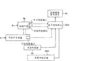
图1是示意性地示出根据本发明的用于车辆的车轮组件的轮胎危险判定设备的实施方式的整体框图。FIG. 1 is an overall block diagram schematically showing an embodiment of a tire risk determination apparatus for a wheel assembly of a vehicle according to the present invention.
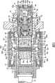
图2是详细示出图1所示的轮胎气腔和气压产生设备的主要部分的纵向正视图。Fig. 2 is a longitudinal front view showing in detail the main part of the tire air cavity and the air pressure generating device shown in Fig. 1 .
图3是图1和图2所示的气压产生设备的剖视图。Fig. 3 is a sectional view of the air pressure generating device shown in Figs. 1 and 2 .
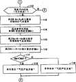
图4是示出在每个预定计算周期中由图1所示的电子控制单元的微型计算机所重复执行的程序的一部分的流程图。FIG. 4 is a flowchart showing a part of a program repeatedly executed by the microcomputer of the electronic control unit shown in FIG. 1 in every predetermined calculation cycle.
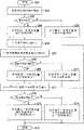
图5是示出在每个个预定计算周期中由图1所示的电子控制单元的微型计算机所重复执行的程序的另一部分的流程图。FIG. 5 is a flow chart showing another part of the program repeatedly executed by the microcomputer of the electronic control unit shown in FIG. 1 every predetermined calculation cycle.
图6是示出每次当驾驶员指定特定位置时由图1所示的电子控制单元的微型计算机所执行的程序的一部分的流程图。FIG. 6 is a flowchart showing a part of the program executed by the microcomputer of the electronic control unit shown in FIG. 1 every time the driver designates a specific position.
具体实施方式Detailed ways
以下将基于附图描述根据本发明的实施例。图1示意性地示出了根据本发明用于车辆的车轮组件的轮胎危险判定设备的实施例。轮胎危险判定设备具有对车辆的车轮组件B的轮胎气腔Rb的气压(P)进行检测的压力传感器S1、对轮胎气腔Rb的气温(T)进行检测的温度传感器S2、以及能够向车轮组件B的轮胎气腔Rb供应增压空气的气压产生设备A。如图2所示,轮胎气腔Rb由车轮组件B的车轮B1及车轮B2形成,并在其内部具有对轮胎气腔Rb的气压(P)进行检测的压力传感器S1以及对轮胎气腔Rb的气温(T)进行检测的温度传感器S2。Embodiments according to the present invention will be described below based on the drawings. FIG. 1 schematically shows an embodiment of a tire risk judging apparatus for a wheel assembly of a vehicle according to the present invention. The tire risk judging device has a pressure sensor S1 for detecting the air pressure (P) of the tire air cavity Rb of the wheel assembly B of the vehicle, a temperature sensor S2 for detecting the air temperature (T) of the tire air cavity Rb, and a sensor capable of sending the wheel assembly B The tire air cavity Rb of B supplies the air pressure generating device A of pressurized air. As shown in FIG. 2 , the tire air chamber Rb is formed by the wheel B1 and the wheel B2 of the wheel assembly B, and has a pressure sensor S1 for detecting the air pressure (P) of the tire air chamber Rb and a pressure sensor S1 for detecting the air pressure (P) of the tire air chamber Rb inside. Air temperature (T) is detected by the temperature sensor S2.
如图2及图3详细示出的,气压产生设备A安装至与车轮组件B一起转动的车轴轮毂11。驱动轴12通过键槽装配至车轴轮毂11的车辆内侧端部,并连接至该端部以传递转矩。通过锁紧螺母13将车轴轮毂11与驱动轴12的连接固定。As shown in detail in FIGS. 2 and 3 , the air pressure generating device A is mounted to an axle hub 11 that rotates with the wheel assembly B. As shown in FIG. The
气压产生设备A具有:与车轴轮毂11的轴部(转轴)11a共轴布置的气泵20、压力控制阀30以及调节设备40,以及共轴布置在压力控制阀30内的安全阀50。气泵20、压力控制阀30和调节设备40这三者中,气泵20布置在车辆最内侧。压力控制阀30布置在气泵20与调节设备40之间。在气泵20、压力控制阀30以及调节设备40中,调节设备40布置在车辆最外侧。The air pressure generating device A has an
气泵20通过车轮组件B的旋转而被驱动,并在车轮组件B停止旋转时停止驱动。气泵20可基于车轮组件B的旋转、经由压力控制阀30来向车轮组件B的轮胎气腔Rb供应增压空气。气泵20具有不可旋转的圆筒形构件21、形成在车轴轮毂11的轴部11a中的气缸22、作为往复运动体的活塞23、凸轮构件24以及一对凸轮随动件25。The
圆筒形构件21由支撑构件(未示出)以不可旋转的方式支撑。气缸22以可绕车轮组件B的旋转中心旋转的方式经由一对轴承BR1和BR2以及一对密封构件26和27被液密地支撑在圆筒形构件21的内部。一对轴承BR1和BR2在轴向上彼此间隔预定距离,并在轴向将凸轮构件24夹置于其两者之间,并且被置于圆筒形构件21与气缸22之间,由此使得气缸22相对于圆筒形构件21旋转。一对密封构件26和27在轴向上彼此间隔预定距离,并在轴向上将凸轮构件24以及轴承BR1和BR2夹置在两者之间,并且被置于圆筒形构件21与气缸22之间,由此在圆筒形构件21与气缸22之间提供液密密封。The
气缸22包括气缸体22A和气缸盖22B,气缸盖22B以密封并可拆卸的方式与气缸体22A的车辆外侧端部螺纹配合。气缸体22A与车轴轮毂11的轴部11a形成为一体,并具有一对轴向细长孔22a以及沿气缸轴向延伸的气缸孔22b。气缸盖22B是以密封并可拆卸的方式安装至车轴轮毂11的底部封闭的管状帽构件,并具有抽吸/排放通路22c、排放通路22d、引入压力通路22e以及抽吸通路22f。The
一对轴向细长孔22a共同用作导引活塞23和凸轮随动件25(以这些构件可与气缸22一体旋转并可沿活塞轴向往复运动的方式进行导引)的导引装置。一对轴向细长孔22a在气缸22的周向上彼此间隔180度布置。气缸孔22b容纳活塞23,由气缸盖22B封闭车辆外侧端部,并由气缸盖22B和活塞23形成泵腔Ro。A pair of axially
抽吸/排放通路22c与设置在压力控制阀30的阀体31中的连通通路31a定常地连通。抽吸/排放通路22c可经由安装至气缸盖22B的抽吸单向阀Vi(其截面构造为V形环状密封构件)将空气导入泵腔Ro。抽吸/排放通路22c可经由安装至压力控制阀30的阀体31的排放单向阀Vo(其截面构造为V形环状密封构件)将空气从泵腔Ro导出。The suction/discharge passage 22c constantly communicates with the communication passage 31a provided in the valve body 31 of the
排放通路22d是将经由排放单向阀Vo排放至气腔Ra1的增压空气导引至设置在车轴轮毂11中的排放通路11b的通路,并具有设置在气缸盖22B中的沿直径方向的连通孔22d1,以及设置在气缸盖22B的外周上的连通槽22d2。如图2所示,设置在车轴轮毂11中的排放通路11b经由设置在车轮B1中的连通通路Ba与轮胎气腔Rb连通。The discharge passage 22d is a passage that guides the pressurized air discharged to the air chamber Ra1 via the discharge check valve Vo to the
引入压力通路22e是设置在气缸盖22B中的沿气缸直径方向的连通孔,其可将排放通路22d内的增压空气的压力引入到形成在压力控制阀30的阀体31与止挡体32之间的气腔Ra2。抽吸通路22f与设置在压力控制阀30的阀体31中的大气连通通路31d定常地连通,并可与设置在压力控制阀30的阀体31中的连通通路31a连通和隔断。设置在阀体31内的大气连通通路31b经由形成在调节设备40的调节螺丝42内的大气连通通路42b定常地与大气连通。The introduction pressure passage 22e is a communication hole provided in the
活塞23经由一对环形密封构件28及29插入气缸22的气缸孔22b,并以可一体转动的方式地安装至气缸22,并能够沿活塞轴向往复运动。活塞23形成有环形槽23a以及沿活塞直径方向延伸的通孔23b。成对密封构件28及29沿轴向彼此间隔预定距离,并分别在活塞23的轴向端部处介于活塞23与气缸22之间,由此在活塞23与气缸22之间提供气密且液密的密封。The
环形槽23a在成对环形密封构件28及29之间形成在活塞23的外周上,由此在活塞23与气缸22之间形成环形空间R1。环形空间R1通过气缸22的轴向细长孔22a与形成在成对环形密封构件26及27之间的环形空间R2连通。环形空间R1及R2在活塞23轴向往复运动过程中保持体积不变,并通过四个密封构件26、27、28及29被密封。环形空间R1及R2等共同用作用于容纳预定量润滑油的油腔。该油腔容纳轴承BR1及BR2、凸轮构件24、凸轮随动件25、以及压缩盘簧Sp等。An
凸轮构件24由一对凸轮套管24A及24B构成,它们以沿活塞轴向彼此接触的方式设置,并与圆筒形构件21一体(以轴向不可移动方式及不可转动方式)安装。凸轮构件24与气缸22共轴设置。凸轮构件24具有其轴向位置可改变的环形凸轮部24a。凸轮部24a是凸轮槽,该凸轮槽与凸轮随动件25的滚珠25c配合。凸轮部24a具有承受来自凸轮随动件25的滚珠25c的活塞轴向负载(图中的竖直负载)以及活塞径向负载(图中的水平负载)的凸轮表面。该凸轮表面具有V形剖面,并具有沿气缸22的周向的偶数个几何圆周(例如,两个几何圆周)。The
凸轮随动件25具有在活塞23内分为两个零件的轴25a,以及安装至轴25a的辊25b及滚珠25c。凸轮随动件25的轴25a设置在活塞23的通孔23b内,以可沿活塞23的径向移动。凸轮随动件25的滚珠25c在沿活塞径向延伸的端部处与凸轮构件24的凸轮部(凸轮槽)24a配合。通过与凸轮构件24的相对转动,凸轮随动件25可沿轴向移动。The
轴25a用作负载传递元件,其以可沿活塞23的径向(通孔23b的轴向)移动的方式安装在活塞23的通孔23b内。安装在轴25a内的压缩盘簧Sp沿活塞23的径向向外方向向轴25a施力。轴25a是支撑体,其以可旋转的方式支撑辊25b,并在从活塞23的通孔23b突伸出的各个小直径端部处以可旋转的方式支撑辊25b。The
在可旋转地装配至轴25a的各个小直径端部的同时,辊25b可滚动地装配在气缸22的各个轴向细长孔22a内。辊25b与凸轮随动件25的气缸轴向移动相关地沿气缸22的各个轴向细长孔22a滚动。每一个辊25b均在其外端处具有半球形的凹入轴承部。该轴承部可滚动地支撑各个球25c。The
球25c是凸轮随动件25的凸出部,其被辊25b可滚动地支撑并与凸轮构件24的凸轮部(凸轮槽)24a可滚动地配合。通过经由轴25a及辊25b接收压缩盘簧Sp的弹性力,球25c与凸轮构件24的凸轮部(凸轮槽)24a无间隙地弹性配合。The
压缩盘簧Sp是施压装置,用于沿活塞23的径向将凸轮随动件25的滚珠25c朝向凸轮构件24的凸轮部(凸轮槽)24a施压。压缩盘簧Sp以预定预载安装在凸轮随动件25的轴25a的底部封闭安装孔内。The compression coil spring Sp is pressing means for pressing the
在气泵20中,当气缸22(车轴轮毂11)在压力控制阀30的阀体31被保持在图示位置的状态下旋转时,活塞23以及凸轮随动件25随着气缸22一体旋转,并相对于凸轮构件24相对旋转,由此轴向移动。因此,气缸22的转动可转换为活塞23的往复运动。活塞23的往复运动可增大和减小泵腔Ro的体积。因此,可通过抽吸单向阀Vi、连通通路31a以及抽吸/排放通路22c将空气引入泵腔Ro。可通过抽吸/排放通路22c、连通通路31a以及排放单向阀Vo从泵腔Ro排放空气。In the
压力控制阀30安装在气缸盖22B内,并具有阀体31、止挡体32以及压缩盘簧34,压缩盘簧34经由弹簧保持体33与阀体31配合,可控制阀体31的移动时间及移动位置,并可通过调节设备40对施加至阀体31的力进行调节。当轮胎气腔Rb的气压(P)降低至下限设定值P1时,压力控制阀30从工作状态(阀体31抵抗压缩盘簧34及52的施加力从图示位置移动预定距离的状态)被切换至图示状态,由此从泵腔Ro向轮胎气腔Rb供应增压空气。当从泵腔Ro向轮胎气腔Rb供应的增压空气的压力升高至上限设定值P2(P1<P2)时,压力控制阀30从图示状态被切换至工作状态,以限制(停止)从泵腔Ro向轮胎气腔Rb的增压空气的供应。The
阀体31经由排放单向阀Vo以及安装在其外周的环形密封构件35以气密方式并以沿气缸轴向可移动的方式安装在气缸盖22B中。阀体31形成气腔Ra1,气腔Ra1与排放通路22d连通,排放通路22d在阀体31与气缸盖22B之间。阀体31形成气腔Ra2,气腔Ra2经由阀体31与止挡体32之间的引入压力通路22e与排放通路22d连通。止挡体32在其内周安装有环形密封构件36,并在其外周安装有环形密封构件37。止挡体32以气密方式介于气缸盖22B与阀体31之间。止挡体32在车辆外侧的端部处在其外周与气缸盖22B螺纹一体配合。The valve body 31 is mounted in the
在压力控制阀30中,当轮胎气腔Rb的气压(P)降低到下限设定值P1而待升高至上限设定值P2时,将阀体31保持在图示位置。连通通路31a与抽吸通路22f之间的连通被抽吸单向阀Vi阻断。抽吸单向阀Vi允许空气从大气流入轮胎气腔Ro。排放单向阀Vo允许空气从泵腔Ro流向轮胎气腔Rb(图示状态)。在此状态下,抽吸单向阀Vi阻断连通通路31a与抽吸通路22f之间的连通,以对从泵腔Ro进入大气的空流进行限制。排放单向阀Vo限制从轮胎气腔Rb进入泵腔Ro的气流。在此状态(压力控制阀30的ON状态)下,活塞23伴随车轮组件B的旋转而进行的往复运动将大气引入泵腔Ro并将增压空气从泵腔Ro排放至轮胎气腔Rb。In the
在压力控制阀30中,当轮胎气腔Rb的气压(P)升高至上限设定值P2而待降低至下限设定值P1时,阀体31抵抗压缩盘簧34及52的施加力从图示位置移动预定距离,并且尽管具有抽吸单向阀Vi,连通通路31a也与抽吸通路22f连通。抽吸单向阀Vi失去其功能(禁止逆流功能)。连通通路31a与抽吸通路22f连通,以允许泵腔Ro与大气之间的空气流动。排放单向阀Vo限制排放通路22d与连通通路31a之间(即,泵腔Ro与轮胎气腔Rb之间)的气流。在阀体31抵抗压缩盘簧34及52的施加力从图示位置移动预定距离的状态(工作状态)下,阀体31的台阶部与安装在止挡体32的内周的密封构件36发生接触。在此状态(压力控制阀30的OFF状态),即使当活塞23伴随车轮组件B的旋转而往复运动时,引入泵腔Ro的空气也会被压回至大气,并不会从泵腔Ro排放至轮胎气腔Rb。In the
调节设备40具有支撑压力控制阀30的压缩盘簧34的另一端部(在阀体31移动时不可移动的固定侧端部)的弹簧支撑件41,以及可调节弹簧支撑件41的位置的调节螺丝42。弹簧支撑件41检测压力控制阀30的ON和OFF状态,并且是在用于检测调节螺丝42的移动量的行程传感器S3的调节时可移动的部分。利用调节螺丝42,弹簧支撑件41可旋转地配合在半球形的凸出部41A中。The
调节螺丝42与弹簧支撑件41分离,并具有公螺纹部42a及大气连通通路42b。,调节螺丝42以公螺纹部42a与气缸盖22B的母螺纹部22g螺纹配合,以可向前和向后移动。调节螺丝42用作帽体,并从车辆的外侧进行旋转。调节螺丝42在外侧端部处形成有六角头部42c,用于可拆卸地安装手动操作调节工具(未示出)。大气连通通路42b装配有过滤器43。The adjusting
当从泵腔Ro向轮胎气腔Rb供应的增压空气的压力(即,气腔Ra1中的气压(P))等于或高于比上限设定值P2更高的安全设定值P3时,安全阀50将增压空气排放到大气。安全阀50具有阀体51和压缩盘簧52,阀体51可打开和阻断设置在阀体31内的安全通路31c,压缩盘簧52在一个端部(移动侧端部)处与阀体51配合并界定阀体51的移动时机(安全通路31c的打开时机)。When the pressure of the pressurized air supplied from the pump chamber Ro to the tire air chamber Rb (ie, the air pressure (P) in the air chamber Ra1) is equal to or higher than the safety set point P3 higher than the upper limit set point P2,
阀体51沿气缸轴向可移动地安装在压力控制阀30的阀体31内,并与行程传感器S3的杆部45(在调节行程传感器S3时,该杆部能够以对可移动部几乎无抵抗地沿气缸轴向相对移动)接触。压缩盘簧52与在另一端部(固定侧端部)处与弹簧支撑件44(其与弹簧支撑件41一体)配合,并可通过调节设备40对施加在阀体51上的作用力进行调节。在通过调节设备40进行调节时,同时调节压缩盘簧34施加在压力控制阀30的阀体31上的施加力。可以同时调节上限设定值P2和安全设定值P3。The valve body 51 is movably installed in the valve body 31 of the
在安全阀50中,设置在压力控制阀30的阀体31内的安全通路31c可通过安装至阀体31的环形密封构件38与气腔Ra1连通和阻断。压力控制阀30的阀体31抵抗压缩盘簧34及52的作用力沿气缸轴向移动。气腔Ra1与安全通路31c经由密封构件38彼此连通。仅在此状态下,气腔Ra1中的压力才施加至安全通路31c以使安全阀50工作。In the
在此实施例中,如图1所示,压力传感器S1的输出(表示轮胎气腔Rb的气压(P)的电信号)、温度传感器S2的输出(表示轮胎气腔Rb的气温(T)的电信号)、以及行程传感器S3的输出(表示压力控制阀30的ON和OFF状态的电信号以及表示调节螺丝42的移动量的电信号)被无线输入至电子控制单元ECU。表示由车速传感器S4检测并输出的车速(或车轮速度(Wr))的电信号以及表示从车载导航设备NAV输出的当前位置到特定位置的距离(Y1至Y6)、从当前位置到特定位置的预定时间(Z1至Z6)、从当前位置到特定位置的直路比例(α1至α6)、以及特定位置的电信号被输入电子控制单元ECU。In this embodiment, as shown in FIG. 1, the output of the pressure sensor S1 (an electrical signal indicating the air pressure (P) of the tire air chamber Rb), the output of the temperature sensor S2 (an electrical signal indicating the air temperature (T) of the tire air chamber Rb electrical signal), and the output of the stroke sensor S3 (electrical signal indicating the ON and OFF states of the
电子控制单元ECU电连接至仪器面板显示单元ID,其可显示包括轮胎气腔Rb的气压系统(具有轮胎气腔Rb以及与其连通的空气通路的系统)的泄漏判定结果,气压产生设备A的判定结果(“气压产生正常”或“气压产生异常”),当前位置的轮胎危险判定结果(“在当前位置存在轮胎危险”或“在当前位置不存在轮胎危险”),特定位置的轮胎危险判定结果(“在特定位置存在轮胎危险”或“在特定位置不存在轮胎危险”),以及“推荐路径Xx”。The electronic control unit ECU is electrically connected to the instrument panel display unit ID, which can display the leakage determination result of the air pressure system (the system having the tire air cavity Rb and the air passage communicating with it) including the tire air cavity Rb, the determination of the air pressure generating device A Result ("air pressure generation is normal" or "air pressure generation is abnormal"), tire hazard judgment result at the current location ("tire hazard exists at the current location" or "tire hazard does not exist at the current location"), tire hazard judgment result at a specific location ("Tire hazard exists at specific location" or "Tire hazard does not exist at specific location"), and "Recommended route Xx".
电子控制单元ECU具有在每个预定计算周期(例如,1秒)重复执行与图4和图5的流程图对应的程序并在每次驾驶员(驾乘者)指定特定位置时执行与图6的流程图对应的程序的微型计算机。在基于压力传感器S1、温度传感器S2、行程传感器S3及车速传感器S4的输出来驱动轮胎气压产生设备A时,电子控制单元ECU可计算出包括轮胎气腔Rb的气压系统内的剩余气体重量M(Mo),离开包括轮胎气腔Rb的气压系统的泄漏气流速率Mr,以及从气压产生设备A向轮胎气腔Rb排放的排放气流速率Md。电子控制单元ECU还可基于剩余气体重量M(Mo)、泄漏气流速率Mr、排放气流速率Md以及车载导航设备NAV的输出来计算当前位置的轮胎危险判定结果以及特定位置的轮胎危险判定结果。The electronic control unit ECU has the program corresponding to the flow chart of Fig. 4 and Fig. 5 repeatedly executed in each predetermined calculation cycle (for example, 1 second) and executes the program corresponding to Fig. The flowchart corresponds to the program of the microcomputer. When the tire air pressure generating device A is driven based on the outputs of the pressure sensor S1, temperature sensor S2, stroke sensor S3, and vehicle speed sensor S4, the electronic control unit ECU can calculate the remaining gas weight M in the air pressure system including the tire air cavity Rb ( Mo), the leakage air flow rate Mr from the air pressure system including the tire air chamber Rb, and the discharge air flow rate Md from the air pressure generating device A to the tire air chamber Rb. The electronic control unit ECU can also calculate the tire risk determination result at the current position and the tire risk determination result at a specific position based on the remaining gas weight M(Mo), the leakage air flow rate Mr, the exhaust air flow rate Md, and the output of the on-board navigation device NAV.
路上导航设备NAV具有已知的各种功能,包括以下功能:对到达由驾驶员指定的点(特定位置)的路径进行搜索的特定位置路径搜索功能外,具体而言,与驾驶中的要求(例如,优选高速公路和优选普通公路等)对应的路径X1以及多条(例如,五条)路径X2至X6;计算由特定位置路径搜索功能搜索到的路径X1至X6的总距离Y1至Y6(从当前位置到特定位置的距离)并将其输出至电子控制单元ECU的功能;计算路径X1至X6的预定时间Z1至Z6(从当前位置到达特定位置所需的时间)并将其输出至电子控制单元ECU的功能;计算X1至X6的从当前位置到达特定位置的直路比例(α1至α6)并将其输出至电子控制单元ECU的功能;以及将由驾驶员指定的点(特定位置)输出至电子控制单元ECU的功能。The on-road navigation device NAV has known various functions, including the following functions: In addition to the specific position route search function for searching a route to a point (specific position) designated by the driver, specifically, it is compatible with the request during driving ( For example, a route X1 corresponding to a preferred expressway and a preferred general road, etc.) and a plurality of (for example, five) routes X2 to X6; calculating the total distance Y1 to Y6 (from The distance from the current position to the specific position) and output it to the function of the electronic control unit ECU; calculate the predetermined time Z1 to Z6 of the route X1 to X6 (the time required to reach the specific position from the current position) and output it to the electronic control Function of the unit ECU; function of calculating the straight road ratio (α1 to α6) of X1 to X6 from the current position to a specific position and outputting it to the electronic control unit ECU; and outputting the point (specific position) designated by the driver to the electronic Function of the control unit ECU.
在如上所述构造的实施例中,当车辆的点火开关(未示出)处于ON时,可以使用车载导航设备NAV。电子控制单元ECU的微型计算机在每个预定计算周期(例如,1秒)重复执行与图4及图5的流程图对应的程序。当车辆停止和车辆行驶时压力控制阀30处于OFF时(增压空气不能供应至轮胎气腔Rb),计算从包括轮胎气腔Rb的气压系统离开的泄漏气流速率Mr(g/秒),并基于泄漏气流速率Mr来判定包括轮胎气腔Rb的气压系统的泄漏。当车辆行驶时压力控制阀30处于ON时(可向轮胎气腔Rb供应增压空气),计算从气压产生设备A向轮胎气腔Rb排放的排放气流速率Md(g/秒),并基于排放气流速率Md以及此时的车速(车轮速度)Wr(m/秒)来计算每单位距离的排放空气量Qi(g/m),由此判定气压产生设备A是正常还是异常。In the embodiment constructed as described above, the in-vehicle navigation device NAV can be used when the ignition switch (not shown) of the vehicle is ON. The microcomputer of the electronic control unit ECU repeatedly executes the program corresponding to the flowcharts of FIGS. 4 and 5 every predetermined calculation period (for example, 1 second). When the
电子控制单元ECU的微型计算机在图4的步骤101中开始处理并在步骤S102中读取并存储压力传感器S1的输出(P)、温度传感器S2的输出(T)、以及车速传感器S4的输出(Wr)。电子控制单元ECU的微型计算机在步骤103中基于气态方程
在图4的步骤104中,电子控制单元ECU的微型计算机判定车速传感器S4的输出(Wr)是否为零(气压产生设备A是否停止并且增压空气不能被供应至轮胎气腔Rb)。如果“是”(增压空气不能被供应至轮胎气腔Rb),则电子控制单元ECU的微型计算机执行步骤105。如果“否”,则其执行图5的步骤112。In
在图4的步骤105中,电子控制单元ECU的微型计算机将步骤103中获得的剩余气体重量M(当前计算值)与剩余气体重量Mo(先前计算值,即,当1秒前执行程序时的计算值)。当此剩余气体重量M小于先前剩余气体重量Mo时(当空气从包括轮胎气腔Rb的气压系统泄漏时),电子控制单元ECU的微型计算机将此判定为“是”,以执行步骤第一透镜单元106和107。当此剩余气体重量M不小于先前剩余重量Mo时,将此判定为“否”,以执行步骤109、110和111。In
在图4的步骤106中,电子控制单元ECU的微型计算机根据先前剩余气体重量Mo与当前剩余气体重量M的差值(Mo-M)来计算并存储泄漏气流速率Mr。在步骤107,电子控制单元ECU的微型计算机判定泄漏气流速率Mr是否大于预定泄漏允许上限值Mr1。如果“是”,则电子控制单元ECU的微型计算机执行步骤108、110及111。如果“否”,则其执行步骤109、110及111。In
在图4的步骤108中,电子控制单元ECU的微型计算机命令显示“泄漏异常”。仪器面板显示单元ID显示“泄漏异常”。在步骤109,电子控制单元ECU的微型计算机命令显示“泄漏正常”。仪器面板显示单元ID显示“泄漏正常”。在步骤110,电子控制单元ECU的微型计算机将当前剩余气体重量M重写为先前剩余气体重量Mo,并将其存储。在步骤111,电子控制单元ECU的微型计算机结束对上述程序的执行。In
在图5的步骤112,电子控制单元ECU的微型计算机基于行程传感器S3的输出(表示压力控制阀30的ON和OFF状态的电信号)来判定压力控制阀30是否处于ON(压力控制阀30是否可向轮胎气腔Rb供应增压空气)。如果“是”,则电子控制单元ECU的微型计算机执行图5的步骤113、114、115、116及117。如果“否”,则其返回至图4的步骤105以执行步骤105。In
在图5的步骤113中,电子控制单元ECU的微型计算机基于当前剩余气体重量M与先前剩余气体重量Mo之间的差值(M-Mo)来计算并存储从气压产生设备A向包括轮胎气腔Rb的气压系统供应的供应气流速率Mp。在步骤114,电子控制单元ECU的微型计算机参考基于车速传感器S4的输出(Wr)的对照图(该图(未示出)表示气压产生设备A的排放允许下限值Md1与车速之间的关系)以获得并存储气压产生设备A的排放允许下限值Md1。In
在图5的步骤115中,电子控制单元ECU的微型计算机根据在步骤113获得的供应气流速率Mp以及在图4的步骤106获得的泄漏气流速率Mr,计算并存储在驱动气压产生设备A时从气压产生设备A向轮胎气腔Rb排放的排放气流速率Md。在步骤116中,电子控制单元ECU的微型计算机根据在步骤115获得的排放气流速率Md以及车速(Wr)来计算并存储每单位距离的排放空气量Qi(g/m)。In
在图5的步骤117中,电子控制单元ECU的微型计算机判定在步骤115获得的排放气流速率Md是否小于在步骤114获得的排放允许下限值Md1。如果“是”,则电子控制单元ECU的微型计算机执行步骤118,然后执行图4的步骤110及111。如果“否”,则其执行步骤119,然后执行图4的步骤110及111。In
在图5的步骤118中,电子控制单元ECU的微型计算机命令显示“气压产生异常”。仪器面板显示单元ID显示“气压产生异常”。在步骤119,电子控制单元ECU的微型计算机命令显示“气压产生正常”。仪器面板显示单元ID显示“气压产生正常”。In
在本实施例中,当车辆的点火开关(未示出)处于ON时,可以使用车载导航设备NAV。驾驶员使用车载导航设备NAV来与要求(例如,优选高速公路以及优选普通公路等)一起输入特定位置。车载导航设备NAV执行已知的操作(包括:搜索从当前位置到特定位置的路径X1至X6的操作),并向电子控制单元ECU输出路径X1至X6的总距离Y1至Y6,路径X1至X6的预定时间Z1至Z6,在路径X1至X6上从当前位置到特定位置的直路比例α1至α6,以及由驾驶员指定的点(特定位置)。电子控制单元ECU的微型计算机执行与图6的流程图对应的程序,并判定当前位置轮胎危险以及特定位置轮胎危险。驾驶员的特定位置输入可以是时间(例如,一小时后的点),而不是输入前的位置名称,设定目的地并确定路径X1。In this embodiment, the vehicle navigation device NAV can be used when the vehicle's ignition switch (not shown) is ON. The driver uses the in-vehicle navigation device NAV to input a specific location along with requirements (eg, preferred expressways and preferred public roads, etc.). The on-board navigation device NAV performs known operations (including: the operation of searching for routes X1 to X6 from the current location to a specific location), and outputs the total distance Y1 to Y6 of the routes X1 to X6 to the electronic control unit ECU, and the routes X1 to X6 The predetermined time Z1 to Z6 of the route X1 to X6, the straight road ratios α1 to α6 from the current position to the specific position on the route X1 to X6, and the point (specific position) designated by the driver. The microcomputer of the electronic control unit ECU executes the program corresponding to the flowchart of FIG. 6 , and determines the tire danger at the current position and the tire danger at the specific position. The driver's location-specific input can be a time (eg, a point one hour later), rather than a location name before the entry, setting the destination and determining the route X1.
在图6的步骤201中,电子控制单元ECU的微型计算机开始进行处理,并在步骤202中,其读取并存储压力传感器S1的输出(P)以及车载导航设备NAV的输出(路径X1至X6的总距离Y1至Y6,路径X1至X6的预定时间Z1至Z6,路径X1至X6的直路比例α1至α6,以及特定位置)。电子控制单元ECU的微型计算机在步骤203判定轮胎气腔Rb在当前位置的气压(P)是否低于轮胎危险判定基准值Po(Po<P1)。如果“是”,则电子控制单元ECU的微型计算机执行步骤204、206、207及208。如果“否”,则其执行步骤205及215。In
在图6的步骤204中,电子控制单元ECU的微型计算机命令显示“在当前位置存在轮胎危险”。仪器面板显示单元ID显示“在当前位置存在轮胎危险”。在图6的步骤205中,电子控制单元ECU的微型计算机命令显示“在当前位置不存在轮胎危险”。仪器面板显示单元ID显示“在当前位置不存在轮胎危险”。In
在图6的步骤206中,电子控制单元ECU的微型计算机计算并存储在路径X1至X6上行驶时轮胎气腔Rb在特定位置的气压(Ps1至Ps6)。在此情况下,通过将通过在图5的步骤116中获得的每单位距离排放空气量Qi(g/m)与在图6的步骤202中获得的路径X1至X6的总距离Y1至Y6(m)的乘积而获得的空气供应量加上在图4的步骤103或110获得的包括轮胎气腔Rb的气压系统在当前位置的剩余气体重量M或Mo得到和值,并通过从上述和值减去通过在图4的步骤106中获得的泄漏气流速率Mr(g/秒)与在图6的步骤202中获得的路径X1至X6的预定时间Z1至Z6(秒)的乘积而获得的空气泄漏量,来计算并存储包括轮胎气腔Rb的气压系统在特定位置的剩余空气重量(Ms1至Ms6)(例如,在路径X1的情况下,Ms1=M+Qi×Y1-Mr×Z1)。In
基于如上所述计算得到的剩余空气重量(Ms1至Ms6)利用气态方程来计算并存储在路径X1至X6上行驶时轮胎气腔Rb在特定位置的气压(Ps1至Ps6)(例如,在路径X1的情况下,
在图6的步骤207中,电子控制单元ECU的微型计算机基于在图6的步骤202中获得的路径X1至X6的直路比例α1至α6来计算并存储在路径X1至X6上行驶时的轮胎负载系数Kb1至Kb6。轮胎负载系数Kb1至Kb6根据施加在车轮组件B的车轮B2上的负载的增大而增大,并根据路径的直路比例增大接近“1”而减小。In step 207 of FIG. 6 , the microcomputer of the electronic control unit ECU calculates and stores the tire load when traveling on the routes X1 to X6 based on the straight road ratios α1 to α6 of the routes X1 to X6 obtained in
在图6的步骤208中,电子控制单元ECU的微型计算机判定在与驾驶员的要求对应的路径X1上行驶时轮胎气腔Rb在特定位置的气压Ps1是否小于考虑轮胎负载而校正的轮胎危险判定基准值Po/Kb1。如果“是”,则电子控制单元ECU的微型计算机执行步骤209、211及212。如果“否”,则其执行步骤210及215。In
在图6的步骤209中,电子控制单元ECU的微型计算机命令显示“在特定位置存在轮胎危险”。仪器面板显示单元ID显示“在特定位置存在轮胎危险”。在图6的步骤210中,电子控制单元ECU的微型计算机命令显示“在特定位置不存在轮胎危险”。仪器面板显示单元ID显示“在特定位置不存在轮胎危险”。在图6的步骤211中,电子控制单元ECU的微型计算机从在步骤206中获得的气压Ps1至Ps6中选择最大值Px,并将其与路径(推荐路径Xx)一同存储。In
在图6的步骤212中,电子控制单元ECU的微型计算机判定在步骤211中选择的气压的最大值Px(Ps1至Ps6中一者)是否小于考虑轮胎负载而校正的轮胎危险判定基准值Po/Kbx(Kb1至Kb6中与Px对应的一个)。如果“是”,电子控制单元ECU的微型计算机执行步骤213及215。如果“否”,其执行步骤214及215。In
在图6的步骤213中,电子控制单元ECU的微型计算机命令显示“在特定位置存在轮胎危险”以及“推荐路径Xx”。仪器面板显示单元ID显示“在特定位置存在轮胎危险”以及“推荐路径Xx”。在图6的步骤214中,电子控制单元ECU的微型计算机命令显示“在特定位置不存在轮胎危险”以及“推荐路径Xx”。仪器面板显示单元ID显示“在特定位置不存在轮胎危险”以及“推荐路径Xx”。在步骤215,电子控制单元ECU的微型计算机结束程序的执行。In
总而言之,在本实施例中,可以根据通过执行图6的步骤208获得的特定位置的轮胎危险判定结果来判定在特定位置的轮胎危险。根据在仪器面板显示单元ID上显示“在特定位置存在轮胎危险”的判定结果,能够告知驾驶员需要在车辆从当前位置到达特定位置之前立即修理轮胎B2。根据在仪器面板显示单元ID上显示的“在特定位置不存在轮胎危险”的判定结果,能够告知驾驶员在车辆从当前位置到达特定位置之前均无需修理轮胎B2。可以很好的时机来执行对车轮B2的修理以避免轮胎危险。In a word, in this embodiment, the tire risk at a specific position can be determined according to the tire risk determination result at a specific position obtained by executing
在本实施例中,可以根据通过执行图6的步骤203获得的当前位置轮胎危险的判定结果来判定在当前位置的轮胎危险。可以根据通过执行图6的步骤208获得的特定位置的轮胎危险判定结果来判定在特定位置的轮胎危险。根据在仪器面板显示单元ID上显示的“在特定位置存在轮胎危险”以及“在当前位置存在轮胎危险”的判定结果,能够告知驾驶员需要在当前位置立即修理轮胎B2。In this embodiment, the tire risk at the current position may be determined according to the determination result of the tire risk at the current position obtained by executing
根据在仪器面板显示单元ID上显示的“在特定位置不存在轮胎危险”以及“在当前位置不存在轮胎危险”的判定结果,能够告知驾驶员无需修理轮胎B2。根据在仪器面板显示单元ID上显示的“在特定位置存在轮胎危险”以及“在当前位置不存在轮胎危险”的判定结果,能够告知驾驶员当车辆从当前位置到达特定位置时需要修理轮胎B2。根据在仪器面板显示单元ID上显示的“在特定位置不存在轮胎危险”以及“在当前位置存在轮胎危险”的判定结果,能够告知驾驶员需要修理轮胎B2,并且在车辆从当前位置到达特定位置之前无需修理轮胎B2。According to the determination results of "there is no tire danger at the specific position" and "there is no tire danger at the current position" displayed on the instrument panel display unit ID, the driver can be notified that tire B2 does not need to be repaired. According to the determination results of "tire danger exists at a specific position" and "tire danger does not exist at the current position" displayed on the instrument panel display unit ID, the driver can be notified that the tire B2 needs to be repaired when the vehicle reaches the specific position from the current position. According to the judgment results of "there is no tire danger at the specific position" and "there is a tire danger at the current position" displayed on the instrument panel display unit ID, the driver can be notified that tire B2 needs to be repaired, and when the vehicle reaches the specific position from the current position Tire B2 did not need to be repaired before.
在本实施例中,执行图6的步骤213及214以在仪器面板显示单元ID上显示“推荐路径Xx”。推荐路径Xx是当车辆从当前位置行驶至特定位置时轮胎气腔Rb的气压(Ps1至Ps6)最大的路径(X1至X6中的一者)。可经由在特定位置的轮胎危险程度最低的路径(即,推荐路径Xx)来从当前位置行驶至特定位置。In this embodiment, steps 213 and 214 in FIG. 6 are executed to display "recommended route Xx" on the instrument panel display unit ID. The recommended route Xx is a route (one of X1 to X6 ) in which the air pressure ( Ps1 to Ps6 ) of the tire air chamber Rb is the largest when the vehicle travels from the current position to the specific position. Traveling from the current location to the particular location may be via the path of least risk to the tires at the particular location (ie, the recommended route Xx).
在上述实施例中,在图4的步骤103中的气态方程中,包括轮胎气腔Rb的气压系统的体积是常量(Vo)。其可以是根据轮胎气腔Rb的气压(P)及气温(T)改变的体积(V)。在此情况下,相较于上述实施例,可以高精度计算气压系统中的剩余气体重量M、泄漏气流速率Mr及供应气流速率Mp。在本发明的实施例中,上述实施例的气温(T)是常量(To),并可以简单计算出气压系统中的剩余气体重量M、泄漏气流速率Mr及供应气流速率Mp。在此情况下,就无需温度传感器S2,由此可简化用于车辆的车轮组件的轮胎危险判定装置。In the above-described embodiment, in the gaseous state equation in
在上述实施例中,在仪器面板显示单元ID上显示各种判定结果以告知驾驶员(驾乘者)。可通过扬声器利用声音来向驾驶员(驾乘者)告知判定结果。在上述实施例中,气压产生设备A通过车轮组件B的旋转而被驱动。气压产生设备可由电动机驱动。In the above-described embodiments, various determination results are displayed on the instrument panel display unit ID to inform the driver (occupant). The driver (passenger) can be notified of the determination result by sound through a speaker. In the above-described embodiments, the air pressure generating device A is driven by the rotation of the wheel assembly B. As shown in FIG. The air pressure generating device may be driven by an electric motor.
在上述实施例中,基于路径X1至X6的直路比例α1至α6来计算轮胎B2上的负载(轮胎负载系数Kb1至Kb6)。可基于弯路比例(弯路总距离/路径总距离)以及包含车辆有效载荷的车辆总重来进行计算。In the above-described embodiment, the load on the tire B2 (tire load coefficients Kb1 to Kb6 ) is calculated based on the straight road ratios α1 to α6 of the routes X1 to X6 . The calculation may be based on the curve ratio (total curve distance/total path distance) and the gross vehicle weight including the vehicle payload.
Claims (9)
Translated fromChineseApplications Claiming Priority (3)
| Application Number | Priority Date | Filing Date | Title |
|---|---|---|---|
| JP2006151815AJP4435114B2 (en) | 2006-05-31 | 2006-05-31 | Tire risk judgment device for vehicle wheels |
| JP151815/2006 | 2006-05-31 | ||
| PCT/JP2007/060316WO2007138899A1 (en) | 2006-05-31 | 2007-05-15 | Tire risk judging device of wheel assembly for vehicle |
Publications (2)
| Publication Number | Publication Date |
|---|---|
| CN101460322A CN101460322A (en) | 2009-06-17 |
| CN101460322Btrue CN101460322B (en) | 2011-03-23 |
Family
ID=38289119
Family Applications (1)
| Application Number | Title | Priority Date | Filing Date |
|---|---|---|---|
| CN2007800203377AExpired - Fee RelatedCN101460322B (en) | 2006-05-31 | 2007-05-15 | Tire risk judging device of wheel assembly for vehicle |
Country Status (6)
| Country | Link |
|---|---|
| US (1) | US7839274B2 (en) |
| EP (1) | EP2021194B1 (en) |
| JP (1) | JP4435114B2 (en) |
| CN (1) | CN101460322B (en) |
| DE (1) | DE602007006003D1 (en) |
| WO (1) | WO2007138899A1 (en) |
Families Citing this family (11)
| Publication number | Priority date | Publication date | Assignee | Title |
|---|---|---|---|---|
| CN101965503A (en)* | 2007-12-30 | 2011-02-02 | Nvb国际公司 | Measuring and reading the size of a parameter of a remotely positioned device |
| EP2423007B1 (en)* | 2009-04-24 | 2016-09-07 | Toyota Jidosha Kabushiki Kaisha | Device for monitoring tire air pressure |
| CN104540690B (en)* | 2012-02-07 | 2017-05-03 | 斯太姆科有限合伙 | Wireless proportional flow indication for tire inflation systems |
| US9310277B2 (en)* | 2012-07-06 | 2016-04-12 | Ta-Min Peng | Tire temperature and tire pressure wireless sensing device |
| GB201315426D0 (en) | 2013-08-29 | 2013-10-16 | Agco Int Gmbh | Tyre inflation control arrangement |
| RU2636242C1 (en) | 2013-12-06 | 2017-11-21 | Дана Хеви Виикл Системз Груп, Ллк | Method to determine pressure in tire |
| CN104191912A (en)* | 2014-09-16 | 2014-12-10 | 成都衔石科技有限公司 | Following automobile tire burst monitoring device |
| DE102015001803A1 (en)* | 2015-02-12 | 2016-08-18 | Man Truck & Bus Ag | Method and device for assisting a driver of a vehicle, in particular a utility vehicle |
| WO2017029554A1 (en)* | 2015-08-14 | 2017-02-23 | Coda Innovations | Tire condition or vehicle monitoring system and method |
| DE102016203685A1 (en)* | 2016-03-07 | 2017-09-07 | Deere & Company | System for tire pressure monitoring for a commercial vehicle |
| CN108674099B (en)* | 2018-05-21 | 2020-04-17 | 温州鑫锐翔科技有限公司 | Temporary detection device for air leakage speed of tire |
Citations (4)
| Publication number | Priority date | Publication date | Assignee | Title |
|---|---|---|---|---|
| EP0166123A2 (en)* | 1984-06-23 | 1986-01-02 | Dr.Ing.h.c. F. Porsche Aktiengesellschaft | Compressed-air supply device for a tyre-pressure regulating system |
| EP0601556B1 (en)* | 1992-12-11 | 1996-07-17 | Compagnie Generale Des Etablissements Michelin-Michelin & Cie | Method for controlling the tyre pressure on vehicles |
| DE19944391A1 (en)* | 1999-04-03 | 2000-10-26 | Continental Teves Ag & Co Ohg | Method and device for influencing the continued travel of a vehicle after a tire pressure loss and method for controlling a tire pressure monitoring system |
| CN1767960A (en)* | 2003-03-28 | 2006-05-03 | 中野隆次 | Air automatic supply mechanism for pneumatic tires |
Family Cites Families (13)
| Publication number | Priority date | Publication date | Assignee | Title |
|---|---|---|---|---|
| JPH0450162A (en) | 1990-06-16 | 1992-02-19 | Agency Of Ind Science & Technol | Production of calcium-doped lanthanum chromite film, burning thereof, calcium-doped lanthanum chromite-based electrocondutive ceramic produced by said method and solid electrolyte fuel cell utilizing said ceramic |
| JPH07137515A (en) | 1993-11-18 | 1995-05-30 | Toyota Motor Corp | Abnormality detection device for tire pressure control device |
| JP3769459B2 (en) | 2000-10-13 | 2006-04-26 | 株式会社豊田中央研究所 | Tire burst prediction device |
| JP2004001671A (en) | 2002-03-25 | 2004-01-08 | Bridgestone Corp | Tire pressure release device |
| JP4029324B2 (en) | 2002-05-02 | 2008-01-09 | 日本電子工業株式会社 | Air pressure detection device and tire condition monitoring system |
| JP2005212669A (en) | 2004-01-30 | 2005-08-11 | Toyota Motor Corp | Tire abnormality detection device |
| JP2005297851A (en) | 2004-04-14 | 2005-10-27 | Toyota Motor Corp | Wheel condition adjustment system |
| JP4333467B2 (en) | 2004-04-28 | 2009-09-16 | 株式会社デンソー | Tire pressure detector |
| GB0415258D0 (en)* | 2004-07-07 | 2004-08-11 | Wheelright Ltd | Vehicle tyre checking system |
| US20060010961A1 (en)* | 2004-07-19 | 2006-01-19 | Alex Gibson | Method and apparatus for detecting leakage rate in a tire pressure monitoring system |
| WO2006053318A2 (en)* | 2004-11-12 | 2006-05-18 | Richard Loewe | Tire pressure maintenance device |
| JP4241587B2 (en)* | 2004-11-25 | 2009-03-18 | トヨタ自動車株式会社 | Wheel state monitoring device and wheel state monitoring method |
| FR2895937B1 (en)* | 2006-01-06 | 2010-04-09 | Michelin Soc Tech | WHEEL AND PNEUMATIC ASSEMBLY COMPRISING PASSIVE DEFLATER MEANS, PRESSURE REGULATION SYSTEM, WHEEL, PNEUMATIC, AND PRESSURE CONTROL METHOD |
- 2006
- 2006-05-31JPJP2006151815Apatent/JP4435114B2/ennot_activeExpired - Fee Related
- 2007
- 2007-05-15USUS11/915,036patent/US7839274B2/ennot_activeExpired - Fee Related
- 2007-05-15CNCN2007800203377Apatent/CN101460322B/ennot_activeExpired - Fee Related
- 2007-05-15WOPCT/JP2007/060316patent/WO2007138899A1/enactiveApplication Filing
- 2007-05-15EPEP07743750Apatent/EP2021194B1/ennot_activeCeased
- 2007-05-15DEDE602007006003Tpatent/DE602007006003D1/enactiveActive
Patent Citations (4)
| Publication number | Priority date | Publication date | Assignee | Title |
|---|---|---|---|---|
| EP0166123A2 (en)* | 1984-06-23 | 1986-01-02 | Dr.Ing.h.c. F. Porsche Aktiengesellschaft | Compressed-air supply device for a tyre-pressure regulating system |
| EP0601556B1 (en)* | 1992-12-11 | 1996-07-17 | Compagnie Generale Des Etablissements Michelin-Michelin & Cie | Method for controlling the tyre pressure on vehicles |
| DE19944391A1 (en)* | 1999-04-03 | 2000-10-26 | Continental Teves Ag & Co Ohg | Method and device for influencing the continued travel of a vehicle after a tire pressure loss and method for controlling a tire pressure monitoring system |
| CN1767960A (en)* | 2003-03-28 | 2006-05-03 | 中野隆次 | Air automatic supply mechanism for pneumatic tires |
Non-Patent Citations (1)
| Title |
|---|
| JP特开2005-297851A 2005.10.27 |
Also Published As
| Publication number | Publication date |
|---|---|
| WO2007138899A1 (en) | 2007-12-06 |
| EP2021194B1 (en) | 2010-04-21 |
| DE602007006003D1 (en) | 2010-06-02 |
| CN101460322A (en) | 2009-06-17 |
| JP2007320400A (en) | 2007-12-13 |
| EP2021194A1 (en) | 2009-02-11 |
| US7839274B2 (en) | 2010-11-23 |
| US20100001852A1 (en) | 2010-01-07 |
| JP4435114B2 (en) | 2010-03-17 |
Similar Documents
| Publication | Publication Date | Title |
|---|---|---|
| CN101460322B (en) | Tire risk judging device of wheel assembly for vehicle | |
| EP3509876B1 (en) | Tire management system and methods | |
| US7760079B2 (en) | Tire-pressure control apparatus | |
| CN1479678A (en) | Device and method for monitoring the inflation pressure of a vehicle tyre | |
| EP2066505B1 (en) | Tire-pressure control apparatus | |
| US20170174017A1 (en) | System for an air maintenance tire assembly | |
| US20080266073A1 (en) | Method for Monitoring Tire Inflating Operation | |
| JP2007278796A (en) | Air flow rate calculation device | |
| EP2046587B1 (en) | Tire-pressure control apparatus | |
| US10322611B2 (en) | System for an air maintenance tire assembly | |
| KR20140136322A (en) | Tire pressure monitoring system using the GPS and Tire pressure monitoring methods | |
| KR100521173B1 (en) | Apparatus for detecting pressure of air in tire for automobile | |
| KR101104339B1 (en) | TPM Sensor for Automotive Tire | |
| CN101155703A (en) | Tire wheel capable of two phases of air pressure | |
| JP2008110653A (en) | Rollover judgment device | |
| Subramonian | The Importance of Tyre Pressure Toward Safety and Economical Driving (UTeM Press) |
Legal Events
| Date | Code | Title | Description |
|---|---|---|---|
| C06 | Publication | ||
| PB01 | Publication | ||
| C10 | Entry into substantive examination | ||
| SE01 | Entry into force of request for substantive examination | ||
| C14 | Grant of patent or utility model | ||
| GR01 | Patent grant | ||
| CF01 | Termination of patent right due to non-payment of annual fee | Granted publication date:20110323 Termination date:20200515 | |
| CF01 | Termination of patent right due to non-payment of annual fee |