CN101460101A - Electroformed liquid jet surgical instrument - Google Patents
Electroformed liquid jet surgical instrumentDownload PDFInfo
- Publication number
- CN101460101A CN101460101ACNA2007800207166ACN200780020716ACN101460101ACN 101460101 ACN101460101 ACN 101460101ACN A2007800207166 ACNA2007800207166 ACN A2007800207166ACN 200780020716 ACN200780020716 ACN 200780020716ACN 101460101 ACN101460101 ACN 101460101A
- Authority
- CN
- China
- Prior art keywords
- mandrel
- nozzle
- nozzle assembly
- jet
- surgical instrument
- Prior art date
- Legal status (The legal status is an assumption and is not a legal conclusion. Google has not performed a legal analysis and makes no representation as to the accuracy of the status listed.)
- Pending
Links
Images


Classifications
- A—HUMAN NECESSITIES
- A61—MEDICAL OR VETERINARY SCIENCE; HYGIENE
- A61B—DIAGNOSIS; SURGERY; IDENTIFICATION
- A61B17/00—Surgical instruments, devices or methods
- A61B17/32—Surgical cutting instruments
- A61B17/3203—Fluid jet cutting instruments
- A—HUMAN NECESSITIES
- A61—MEDICAL OR VETERINARY SCIENCE; HYGIENE
- A61B—DIAGNOSIS; SURGERY; IDENTIFICATION
- A61B18/00—Surgical instruments, devices or methods for transferring non-mechanical forms of energy to or from the body
- A—HUMAN NECESSITIES
- A61—MEDICAL OR VETERINARY SCIENCE; HYGIENE
- A61B—DIAGNOSIS; SURGERY; IDENTIFICATION
- A61B17/00—Surgical instruments, devices or methods
- A61B17/32—Surgical cutting instruments
- A—HUMAN NECESSITIES
- A61—MEDICAL OR VETERINARY SCIENCE; HYGIENE
- A61M—DEVICES FOR INTRODUCING MEDIA INTO, OR ONTO, THE BODY; DEVICES FOR TRANSDUCING BODY MEDIA OR FOR TAKING MEDIA FROM THE BODY; DEVICES FOR PRODUCING OR ENDING SLEEP OR STUPOR
- A61M37/00—Other apparatus for introducing media into the body; Percutany, i.e. introducing medicines into the body by diffusion through the skin
- A—HUMAN NECESSITIES
- A61—MEDICAL OR VETERINARY SCIENCE; HYGIENE
- A61B—DIAGNOSIS; SURGERY; IDENTIFICATION
- A61B17/00—Surgical instruments, devices or methods
- A61B2017/00526—Methods of manufacturing
Landscapes
- Health & Medical Sciences (AREA)
- Life Sciences & Earth Sciences (AREA)
- Surgery (AREA)
- Engineering & Computer Science (AREA)
- Medical Informatics (AREA)
- General Health & Medical Sciences (AREA)
- Biomedical Technology (AREA)
- Heart & Thoracic Surgery (AREA)
- Veterinary Medicine (AREA)
- Public Health (AREA)
- Animal Behavior & Ethology (AREA)
- Nuclear Medicine, Radiotherapy & Molecular Imaging (AREA)
- Molecular Biology (AREA)
- Otolaryngology (AREA)
- Dermatology (AREA)
- Anesthesiology (AREA)
- Hematology (AREA)
- Surgical Instruments (AREA)
- Infusion, Injection, And Reservoir Apparatuses (AREA)
Abstract
Description
Translated fromChinese技术领域technical field
本发明总体上涉及用于产生液体射流的外科器械和用于制造所述器械的方法。The present invention generally relates to a surgical instrument for producing a liquid jet and a method for manufacturing the same.
背景技术Background technique
用于工业切割操作的液体射流切割器械是已知的,并且已被改装用于更小规模和更精确的手术。特别地,某些这样的装置已被改装用于外科手术。工业切割成功地改装用于外科/医疗用途需要许多变化。Liquid jet cutting instruments for industrial cutting operations are known and have been adapted for smaller and more precise procedures. In particular, some of these devices have been adapted for use in surgery. Many changes are required for industrial cutting to be successfully adapted for surgical/medical use.
已经开发出了用于外科手术的各种液体射流器械,包括在以下文献中描述的器械:共同拥有的美国专利No.5,944,686,美国专利No.6,375,635,美国专利No.6,511,493,美国专利No.6,451,017,美国专利No.7,122,017,美国专利No.6,960,182,公开号为US2003-0125660的美国申请,公开号为US2002-0176788的美国申请,公开号为US2004-0228736的美国申请,公开号为US2004-0243157的美国申请,公开号为US2006-0264808的美国申请,和公开号为US2006-0229550的美国申请,上述文献全文被引用于此作为参考。Various liquid jet devices have been developed for use in surgical procedures, including those described in commonly owned U.S. Patent No. 5,944,686, U.S. Patent No. 6,375,635, U.S. Patent No. 6,511,493, U.S. Patent No. 6,451,017 , U.S. Patent No. 7,122,017, U.S. Patent No. 6,960,182, U.S. Application Publication No. US2003-0125660, U.S. Application Publication No. US2002-0176788, U.S. Application Publication No. US2004-0228736, U.S. Application Publication No. US2004-0243157 US Application, US Application Publication No. US2006-0264808, and US Application Publication No. US2006-0229550, the entire contents of which are incorporated herein by reference.
尽管当前可用的液体射流外科器械在一些情况下表现出优于用于执行开放式和微创外科手术的许多现有技术的外科器械的显著改进,然而在本领域中仍然需要提供制造液体射流外科器械的改进方法。本发明在许多实施方式中提供了制造各种类型的液体射流形成外科器械的改进方法。某些实施方式涉及以可容易再现的方式制造液体射流外科器械的喷嘴组件的方法。Although currently available liquid jet surgical instruments represent in some instances significant improvements over many prior art surgical instruments used to perform open and minimally invasive surgical procedures, there remains a need in the art to provide Improvements to equipment. The present invention, in many embodiments, provides improved methods of making various types of liquid jet forming surgical instruments. Certain embodiments relate to methods of manufacturing nozzle assemblies for liquid jet surgical instruments in an easily reproducible manner.
发明内容Contents of the invention
在本发明的上下文中确定和认识了几个问题和制造难题。在设计和制造外科器械中的一个主要难题在于在完成该程序之后所述器械或系统的至少接触患者的部分优选地是可置换的。由于器械的部分是可置换的,有利的是以简单和可重复的方式制造这些部件。Several issues and manufacturing challenges were identified and recognized in the context of the present invention. A major challenge in designing and manufacturing surgical instruments is that at least the portion of the instrument or system that contacts the patient is preferably replaceable after completion of the procedure. Since parts of the instrument are replaceable, it is advantageous to manufacture these parts in a simple and repeatable manner.
另外,某些外科器械能够通过利用抽吸,或者用某些形成液体射流的外科器械通过使用临界压力从手术部位排出材料,所述临界压力可以由高速射流进入合适的排出管生成而不需要附加抽吸(例如,参见共同拥有的美国专利No.6,375,635)。而且,手术部位可以在身体的内部并且可能是不容易观察的。所以,在形成液体射流的外科器械中重要的是射流发射喷嘴与排出管的进入口精确地对准。Additionally, certain surgical instruments are capable of expelling material from the surgical site by the use of suction, or with certain surgical instruments that form jets of liquid, by the use of critical pressures that can be generated by high-velocity jets into a suitable discharge tube without the need for additional Suction (see, eg, commonly owned US Patent No. 6,375,635). Also, the surgical site may be inside the body and may not be readily visible. Therefore, in surgical instruments that form a liquid jet, it is important that the jet emitting nozzle is precisely aligned with the inlet opening of the discharge tube.
在医疗用途的制造中的进一步难题在于某些结构可能需要在高压流体的路径中的180度弯曲,使得液体射流沿着液体被供应的方向被向回引导。A further difficulty in manufacturing for medical use is that certain structures may require a 180 degree bend in the path of the high pressure fluid so that the liquid jet is directed back in the direction in which the liquid was supplied.
在制造用于医疗和外科用途的液体射流器械中的另一主要难题是需要大规模制造尺寸精确和可再现的射流形成喷嘴或孔口,和需要在器械内精确和可再现地对准它们,同时最小化制造步骤的数量和复杂性。Another major challenge in the manufacture of liquid jet devices for medical and surgical use is the need to mass-produce dimensionally accurate and reproducible jet-forming nozzles or orifices, and the need to align them precisely and reproducibly within the device, While minimizing the number and complexity of manufacturing steps.
提供了一种通过电铸成形喷嘴组件来制造形成液体射流的外科器械的改进方法。可以在心轴上成形所述喷嘴组件,使得心轴的外表面成形所述喷嘴组件的内表面。一旦所述喷嘴组件被成形,随后可以去除所述心轴。An improved method of manufacturing a liquid jet forming surgical instrument by electroforming a nozzle assembly is provided. The nozzle assembly may be formed on a mandrel such that the outer surface of the mandrel forms the inner surface of the nozzle assembly. Once the nozzle assembly is shaped, the mandrel can then be removed.
在一种实施方式中,将心轴插入到压力管的出口中。可以用导电材料,例如金属涂覆所述心轴和压力管的至少一部分,然后在所述心轴上电铸成形喷嘴组件。在电铸成形之后,可以切割所述喷嘴组件和/或所述心轴的部分,以在所述喷嘴组件中产生喷射口。然后可以选择性地移除所述心轴。In one embodiment, the mandrel is inserted into the outlet of the pressure tube. The mandrel and at least a portion of the pressure tube may be coated with a conductive material, such as a metal, and the nozzle assembly then electroformed on the mandrel. Following electroforming, portions of the nozzle assembly and/or the mandrel may be cut to create injection ports in the nozzle assembly. The mandrel can then be selectively removed.
在一种实施方式中,所述喷嘴组件与所述压力管一体化。在成形喷嘴组件之前或之后,排出管可以连接到压力管,并且可以对准所述排出管,使得通过所述喷嘴组件的喷射口发射的流体射流将进入所述排出管的内腔。In one embodiment, the nozzle assembly is integral with the pressure tube. A discharge tube may be connected to the pressure tube before or after forming the nozzle assembly, and the discharge tube may be aligned such that a fluid jet emitted through the jet opening of the nozzle assembly will enter the lumen of the discharge tube.
在另一种实施方式中,心轴具有:在第一区域中的形状,在心轴上电镀一层并且切割它之后所述形状将形成喷嘴;和在第二区域中的形状,所述形状将形成开口,所述开口可以被切割以暴露心轴材料,使得在切割所述层和选择性地移除心轴材料之后,将形成可以配合在高压管之上或之中的开口。In another embodiment, the mandrel has: a shape in the first region that will form the nozzle after plating a layer on the mandrel and cutting it; and a shape in the second region that will An opening is formed which can be cut to expose the mandrel material so that after cutting the layers and selectively removing the mandrel material an opening will be formed which can fit over or into the high pressure tube.
在一个方面中,本发明提供了一种制造形成液体射流的外科器械的方法,所述形成液体射流的外科器械包括压力管、排出管和喷嘴。在心轴上电铸成形所述外科器械的喷嘴组件,其中所述喷嘴组件包括提供喷射口的至少一个喷嘴,所述喷嘴的形状能够在处于高压下的液体流过所述喷嘴时形成液体射流。从所述喷嘴组件移除所述心轴,并且将所述外科器械的压力管的出口联接到所述喷嘴组件。将所述外科器械的排出管的入口定位成使得当所述器械在操作中时所述排出管的射流接收口与所述喷嘴的喷射口相对地定位,以允许排出口接收液体射流。In one aspect, the present invention provides a method of making a liquid jet-forming surgical instrument comprising a pressure tube, a discharge tube, and a nozzle. A nozzle assembly of the surgical instrument is electroformed on a mandrel, wherein the nozzle assembly includes at least one nozzle providing an injection opening shaped to form a liquid jet when a liquid under high pressure flows through the nozzle. The mandrel is removed from the nozzle assembly, and the outlet of the pressure tube of the surgical instrument is coupled to the nozzle assembly. The inlet of the discharge tube of the surgical instrument is positioned such that the jet receiving opening of the discharge tube is positioned opposite the jet opening of the nozzle when the instrument is in operation to allow the discharge port to receive a liquid jet.
在另一方面中,本发明提供了一种制造形成液体射流的外科器械的方法,所述形成液体射流的外科器械包括压力管、排出管和喷嘴。将所述外科器械的压力管的出口联接到心轴,并且在所述心轴上电铸成形所述外科器械的喷嘴组件,使得所述喷嘴组件一体地连接到所述压力管的出口,其中所述喷嘴组件包括提供喷射口的至少一个喷嘴。所述喷嘴的形状能够在处于高压下的液体流过所述喷嘴时形成液体射流。从所述喷嘴组件移除所述心轴,并且将所述外科器械的排出管的入口定位成使得当所述器械在操作中时所述排出管的射流接收口与所述喷嘴的喷射口相对地定位,以允许排出口接收液体射流。In another aspect, the present invention provides a method of manufacturing a liquid jet-forming surgical instrument comprising a pressure tube, a discharge tube, and a nozzle. coupling the outlet of the pressure tube of the surgical instrument to a mandrel, and electroforming the nozzle assembly of the surgical instrument on the mandrel such that the nozzle assembly is integrally connected to the outlet of the pressure tube, wherein The nozzle assembly includes at least one nozzle providing an injection opening. The nozzle is shaped to form a liquid jet when liquid under high pressure flows through the nozzle. The mandrel is removed from the nozzle assembly, and the inlet of the discharge tube of the surgical instrument is positioned such that the jet-receiving opening of the discharge tube is opposite the jet opening of the nozzle when the instrument is in operation Positioned to allow the discharge port to receive the liquid jet.
在另一方面中,本发明提供了一种制造形成液体射流的外科器械的方法,所述形成液体射流的外科器械包括压力管、排出管和喷嘴。将第一心轴部分联接到所述外科器械的压力管的出口,并且将第二心轴部分联接到所述外科器械的排出管的入口,其中第二心轴部分能够联接到第一心轴部分。在第一和第二心轴部分上电铸成形所述外科器械的喷嘴组件。切割所述喷嘴组件以产生提供喷射口的至少一个喷嘴,所述喷嘴的形状能够在处于高压下的液体流过所述喷嘴时形成液体射流。当所述器械在操作中时,所述排出管的入口的射流接收口与所述喷嘴的喷射口相对地定位,以允许排出口接收液体射流。从所述喷嘴组件移除第一和第二心轴部分。In another aspect, the present invention provides a method of manufacturing a liquid jet-forming surgical instrument comprising a pressure tube, a discharge tube, and a nozzle. coupling the first mandrel part to the outlet of the pressure tube of the surgical instrument, and coupling the second mandrel part to the inlet of the discharge tube of the surgical instrument, wherein the second mandrel part is coupleable to the first mandrel part. A nozzle assembly of the surgical instrument is electroformed on the first and second mandrel portions. The nozzle assembly is cut to produce at least one nozzle providing a jet opening shaped to form a liquid jet when a liquid at high pressure flows through the nozzle. When the instrument is in operation, the jet-receiving opening of the inlet of the discharge tube is positioned opposite the spray opening of the nozzle to allow the discharge opening to receive a jet of liquid. The first and second mandrel sections are removed from the nozzle assembly.
在又一方面中,本发明提供了一种制造形成液体射流的外科器械的方法,所述形成液体射流的外科器械包括压力管、排出管和喷嘴。将大体呈U形的心轴的第一端联接到所述外科器械的压力管的出口。用导电材料涂覆所述大体呈U形的心轴的至少一部分和所述压力管的至少一部分。在所述心轴上电铸成形所述外科器械的喷嘴组件,并且切割所述喷嘴组件以产生提供喷射口的至少一个喷嘴,所述喷嘴的形状能够在处于高压下的液体流过所述喷嘴时形成液体射流。将所述外科器械的排出管的入口定位成使得所述排出管的纵向轴线基本平行于所述压力管的纵向轴线,并且使得当所述器械在操作中时所述排出管的射流接收口与所述喷嘴的喷射口相对地定位,以允许排出口接收液体射流。然后从所述喷嘴组件移除所述大体呈U形的心轴。In yet another aspect, the present invention provides a method of making a liquid jet-forming surgical instrument comprising a pressure tube, a discharge tube, and a nozzle. A first end of a generally U-shaped mandrel is coupled to an outlet of a pressure tube of the surgical instrument. Coating at least a portion of the generally U-shaped mandrel and at least a portion of the pressure tube with a conductive material. electroforming a nozzle assembly of the surgical instrument on the mandrel, and cutting the nozzle assembly to produce at least one nozzle providing a jet opening, the nozzle being shaped to allow a liquid under high pressure to flow through the nozzle forming a liquid jet. The inlet of the exhaust tube of the surgical instrument is positioned such that the longitudinal axis of the exhaust tube is substantially parallel to the longitudinal axis of the pressure tube, and such that the jet receiving opening of the exhaust tube is aligned with the outlet tube when the instrument is in operation. The spray openings of the nozzles are oppositely positioned to allow the discharge openings to receive the liquid jets. The generally U-shaped mandrel is then removed from the nozzle assembly.
在又一方面中,本发明提供了一种制造形成液体射流的外科器械的方法,所述形成液体射流的外科器械包括压力管、排出管和喷嘴。在心轴上电铸成形所述外科器械的喷嘴组件,其中所述喷嘴组件包括提供喷射口的至少一个喷嘴,所述喷嘴的形状能够在处于高压下的液体流过所述喷嘴时形成液体射流。从所述喷嘴组件移除所述心轴并且将所述外科器械的压力管的出口联接到所述喷嘴组件。In yet another aspect, the present invention provides a method of making a liquid jet-forming surgical instrument comprising a pressure tube, a discharge tube, and a nozzle. A nozzle assembly of the surgical instrument is electroformed on a mandrel, wherein the nozzle assembly includes at least one nozzle providing an injection opening shaped to form a liquid jet when a liquid under high pressure flows through the nozzle. The mandrel is removed from the nozzle assembly and the outlet of the pressure tube of the surgical instrument is coupled to the nozzle assembly.
在又一方面中,本发明提供了一种制造形成液体射流的外科器械的方法,所述形成液体射流的外科器械包括压力管和喷嘴。将所述外科器械的压力管的出口联接到心轴,并且在所述心轴上电铸成形所述外科器械的喷嘴组件,使得所述喷嘴组件一体地连接到所述压力管的出口,其中所述喷嘴组件包括提供喷射口的至少一个喷嘴。所述喷嘴的形状能够在处于高压下的液体流过所述喷嘴时形成液体射流。从所述喷嘴组件移除所述心轴。In yet another aspect, the present invention provides a method of making a liquid jet-forming surgical instrument comprising a pressure tube and a nozzle. coupling the outlet of the pressure tube of the surgical instrument to a mandrel, and electroforming the nozzle assembly of the surgical instrument on the mandrel such that the nozzle assembly is integrally connected to the outlet of the pressure tube, wherein The nozzle assembly includes at least one nozzle providing an injection opening. The nozzle is shaped to form a liquid jet when liquid under high pressure flows through the nozzle. The mandrel is removed from the nozzle assembly.
附图说明Description of drawings
附图是示意性的而不是按比例绘制的。在图中,在各个图中示出的每个相同的或基本类似的部件通常由一个数字或符号表示。为了清楚起见,并非在每幅图中都标示每个部件,并且在没有必要显示的情况下也未显示本发明的每种实施方式的每个部件,从而允许本领域的普通技术人员理解本发明,在图中:The drawings are schematic and not drawn to scale. In the drawings, each identical or substantially similar component that is shown in various figures is generally represented by a numeral or symbol. For purposes of clarity, not every component is labeled in every figure, nor is every component of every embodiment of the invention shown where necessary to allow one of ordinary skill in the art to understand the invention ,In the picture:
图1A是带有电铸成形喷嘴组件的形成液体射流的外科器械的示意性横截面图;1A is a schematic cross-sectional view of a liquid jet forming surgical instrument with an electroformed nozzle assembly;
图1B是图1A中所示的外科器械的示意性侧视图;Figure 1B is a schematic side view of the surgical instrument shown in Figure 1A;
图1C是图1A中所示外科器械的详细的示意性横截面图;Figure 1C is a detailed schematic cross-sectional view of the surgical instrument shown in Figure 1A;
图2是根据一种实施方式的制造形成液体射流的外科器械的方法的示意图,其中,排出管联接到压力管,心轴插入在压力管中,并且心轴和压力管涂覆有导电材料;2 is a schematic diagram of a method of manufacturing a liquid jet-forming surgical instrument according to one embodiment, wherein the discharge tube is coupled to a pressure tube, a mandrel is inserted into the pressure tube, and the mandrel and pressure tube are coated with a conductive material;
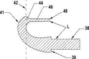
图3A是根据一种实施方式的心轴的示意图;Figure 3A is a schematic illustration of a mandrel according to one embodiment;
图3B是图3A中所示的心轴的示意性横截面图;Figure 3B is a schematic cross-sectional view of the mandrel shown in Figure 3A;
图3C和3D是图3A中所示的心轴的示意性端视图;Figures 3C and 3D are schematic end views of the mandrel shown in Figure 3A;
图4A是在心轴上电铸成形的喷嘴组件的示意性端视图;Figure 4A is a schematic end view of an electroformed nozzle assembly on a mandrel;
图4B是在联接到压力管的心轴上电铸成形的喷嘴组件的示意性横截面图;4B is a schematic cross-sectional view of an electroformed nozzle assembly on a mandrel coupled to a pressure tube;
图4C是根据一种实施方式的电铸成形喷嘴组件的示意图;4C is a schematic illustration of an electroforming nozzle assembly according to one embodiment;
图4D和4E是根据另一种实施方式的电铸成形喷嘴组件的示意图;4D and 4E are schematic illustrations of an electroforming nozzle assembly according to another embodiment;
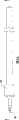
图5A是根据一种实施方式的第二心轴部分的示意图;Figure 5A is a schematic illustration of a second mandrel section according to one embodiment;
图5B是图5A中所示的第二心轴部分的示意性端视图;Figure 5B is a schematic end view of the second mandrel section shown in Figure 5A;
图5C是图5A中所示的第二心轴部分的示意性侧视图;Figure 5C is a schematic side view of the second mandrel section shown in Figure 5A;
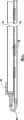
图6A是根据一种实施方式的用于电铸成形喷嘴组件的第一心轴部分和第二心轴部分的示意图;6A is a schematic illustration of a first mandrel portion and a second mandrel portion for an electroformed nozzle assembly according to one embodiment;
图6B是图6A中所示的第一心轴部分和第二心轴部分的示意性侧视图;Figure 6B is a schematic side view of the first and second mandrel sections shown in Figure 6A;
图6C是图6A中所示的第一心轴部分和第二心轴部分的示意性横截面图;Figure 6C is a schematic cross-sectional view of the first and second mandrel sections shown in Figure 6A;
图6D是图6C中所示的外科器械的示意性横截面细节图;Figure 6D is a schematic cross-sectional detail view of the surgical instrument shown in Figure 6C;
图7A是根据一种实施方式的电铸成形到第一心轴部分和第二心轴部分上的喷嘴组件的示意图;7A is a schematic illustration of a nozzle assembly electroformed onto a first mandrel portion and a second mandrel portion according to one embodiment;
图7B是图7A中所示的喷嘴组件的示意性端视图;Figure 7B is a schematic end view of the nozzle assembly shown in Figure 7A;
图7C是图7A中所示的喷嘴组件的示意性横截面图;Figure 7C is a schematic cross-sectional view of the nozzle assembly shown in Figure 7A;
图8A是根据一种实施方式的组织切割表面的示意图;Figure 8A is a schematic illustration of a tissue cutting surface according to one embodiment;
图8B和8C是图8A中所示的在喷嘴组件上的组织切割表面的示意图;8B and 8C are schematic illustrations of the tissue cutting surface on the nozzle assembly shown in FIG. 8A;
图9是根据另一种实施方式的电铸成形喷嘴组件的示意图;Figure 9 is a schematic illustration of an electroforming nozzle assembly according to another embodiment;
图10A和10B是根据另一种实施方式的用于电铸成形喷嘴组件的第一心轴部分和第二心轴部分的示意图;10A and 10B are schematic illustrations of a first mandrel section and a second mandrel section for an electroformed nozzle assembly according to another embodiment;
图11是根据又一种实施方式的用于电铸成形喷嘴组件的第一心轴部分和第二心轴部分的示意图;11 is a schematic illustration of a first mandrel portion and a second mandrel portion for an electroformed nozzle assembly according to yet another embodiment;
图12A是压力管和排出管的示意性横截面图;和Figure 12A is a schematic cross-sectional view of a pressure tube and a discharge tube; and
图12B是根据另一种实施方式的带有辅助管的压力管和排出管的示意性横截面图。Figure 12B is a schematic cross-sectional view of a pressure tube and a discharge tube with auxiliary tubes according to another embodiment.
具体实施方式Detailed ways
在这里公开了用于制造在各种应用中有用的各种液体射流器械的具有创造性的方法和由所述器械形成的各种创新液体射流器械。本发明的器械的某些实施方式尤其适合于各种外科手术。由本发明提供的液体射流器械的某些实施方式可以以各种不同的方式被构造用在各种外科手术领域中。根据本发明,某些外科器械被构造成外科手持件,所述外科手持件具有带抓握区域的近端或手柄,所述近端或手柄被成型和构造成由操作者的手舒适地把持。所述器械也可以具有远端,所述远端包括用于形成液体射流的至少一个喷嘴。本发明的外科器械的某些实施方式的远端可以用于对患者执行外科手术。本发明也可以利用具有各种构造和目的的液体射流器械来实施。由本发明提供的液体射流器械的某些实施方式可以在各种各样的外科应用中被广泛利用,以利用高压液流切割、钻孔、打洞、穿孔、剥离、分层、液化、消融、成型或成形患者的身体的各种组织、器官等。Inventive methods for making various liquid jet devices useful in various applications and various innovative liquid jet devices formed from the devices are disclosed herein. Certain embodiments of the devices of the present invention are particularly suitable for various surgical procedures. Certain embodiments of the liquid jet instruments provided by the present invention can be configured in various ways for use in various surgical fields. In accordance with the present invention, certain surgical instruments are configured as surgical handpieces having a proximal end or handle with a gripping region that is shaped and configured to be comfortably held by an operator's hand . The instrument may also have a distal end comprising at least one nozzle for forming a liquid jet. The distal end of certain embodiments of surgical instruments of the present invention can be used to perform surgical procedures on a patient. The invention may also be practiced with liquid jet devices of various configurations and purposes. Certain embodiments of liquid jet devices provided by the present invention can be widely utilized in a wide variety of surgical applications to cut, drill, punch, perforate, dissect, delaminate, liquefy, ablate, Shape or shape various tissues, organs, etc. of the patient's body.
应当注意的是,用于实施本发明的各种实施方式的液体射流外科器械的各种各样的设计参数、配置、结构材料和其他方面的设计、制造和结构在以下文献中被提供:共同拥有的美国专利Nos.5,944,686;6,375,635;6,511,493;6,451,017;7,122,017;和6,960,182;公开号为2003/0125660 A1,US2002-0176788 A1,US2004-0228736 A1,2004/0243157 A1,US2006-0264808 A1,和US2006-0229550的美国专利申请,上述每个文献被引用于此作为参考。关于这里所述的器械的液体射流部件的某些实施方式的结构和设计,读者可以参考这些发表的专利和专利公开文献以获得详细描述和指导。It should be noted that the design, manufacture and construction of various design parameters, configurations, materials of construction and other aspects of liquid jet surgical instruments for practicing various embodiments of the present invention are provided in the following documents: Common拥有的美国专利Nos.5,944,686;6,375,635;6,511,493;6,451,017;7,122,017;和6,960,182;公开号为2003/0125660 A1,US2002-0176788 A1,US2004-0228736 A1,2004/0243157 A1,US2006-0264808 A1,和US2006- 0229550, each of which is incorporated herein by reference. The reader is referred to these published patents and patent publications for a detailed description and guidance regarding the construction and design of certain embodiments of the liquid jet components of the devices described herein.
本发明的各种实施方式涉及液体射流外科器械,其中在心轴上电铸成形有喷嘴组件。电铸成形是通过在随后被去除的衬底或心轴上的电镀槽中电沉积制造金属部件的工艺。下面提供了电铸成形的简要说明。然而,应当理解的是,本领域技术人员公知的用于一般电铸成形金属部件的方法和设备并未在这里进行详细描述,原因是用于这些工艺的方法并非本质上与现有技术不同。Various embodiments of the invention relate to liquid jet surgical instruments in which a nozzle assembly is electroformed on a mandrel. Electroforming is the process of fabricating metal parts by electrodeposition in an electroplating bath on a substrate or mandrel that is subsequently removed. A brief description of electroforming is provided below. It should be understood, however, that methods and apparatus for electroforming metal parts in general, known to those skilled in the art, have not been described in detail here because the methods used for these processes are not substantially different from the prior art.
喷嘴组件可以位于外科器械的远端处或附近,然而,在该方面本发明不受限制。此外,许多下面所述的实施方式示出了具有喷嘴组件的外科器械,所述喷嘴组件沿近侧方向将射流发射到排出管中。然而,本发明的外科器械可以不同地被构造,原因是本发明并非如此被限制。例如,喷嘴组件能够沿远侧方向或沿侧向发射射流。可以预料具有不同详细规格的各种不同设计用于多种用途。例如,本发明可以在以下文献中公开的许多各种各样的液体射流外科器械结构的制造中实施:共同拥有的美国专利Nos.5,944,686;6,375,635;6,511,493;6,451,017;7,122,017;和6,960,182;公开号为2003/0125660A1,US2002-0176788 A1,US2004-0228736 A1,2004/0243157 A1,US2006-0264808 A1,和US2006-0229550的美国专利申请。The nozzle assembly may be located at or near the distal end of the surgical instrument, however, the invention is not limited in this respect. Additionally, many of the embodiments described below show a surgical instrument having a nozzle assembly that fires a jet in a proximal direction into the exhaust tube. However, the surgical instruments of the present invention may be configured differently, as the invention is not so limited. For example, the nozzle assembly can fire a jet in a distal direction or in a lateral direction. A variety of different designs with different detailed specifications are envisioned for a variety of uses. For example, the present invention may be practiced in the manufacture of many of the various liquid jet surgical instrument structures disclosed in commonly owned U.S. Patent Nos. 5,944,686; 6,375,635; 6,511,493; 6,451,017; US patent applications 2003/0125660A1, US2002-0176788A1, US2004-0228736A1, 2004/0243157A1, US2006-0264808A1, and US2006-0229550.
现在将在附图中示出的几种特定实施方式的上下文中更完整地详细描述某些具有创造性的液体射流外科器械。应当理解的是,所描述的实施方式仅仅是用于示例性目的,并且如所附权利要求书中所述的本发明的新颖性特征可以以其他方式实施或者用于具有其他结构的器械,这对于本领域的普通技术人员来说是可以想到的。Certain inventive liquid jet surgical instruments will now be described in more complete detail in the context of several specific embodiments illustrated in the accompanying drawings. It should be understood that the described embodiments are for illustrative purposes only, and that the novel features of the invention as described in the appended claims may be embodied in other ways or used with instruments having other configurations, which It is conceivable for those of ordinary skill in the art.
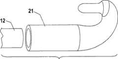
图1A-1C示出了根据本发明的一种实施方式的形成液体射流的外科器械的一种结构。具体而言,图1A示出了器械10的横截面图,图1B示出了器械10的侧视图,图1C示出了图1A中所示的末端区域的细节图。如图所示,在该实施方式中,液体射流26沿近侧方向被引导。在这些图中,外科器械总体上以附图标记10示出,末端区域总体上以附图标记20示出。显示了两个管,具有壁13和内腔14的压力管12,和具有壁17和内腔18的排出管16。具有与压力管内腔14流体连接的内部体积22的电铸成形喷嘴组件21联接到压力管12的出口。在一种实施方式中,喷嘴组件21电铸成形在压力管12的一部分上,例如出口部分上。在另一种实施方式中,喷嘴组件21可以通过在制造喷嘴组件21之后进行连接,例如焊接、熔接、压接、粘结或其他已知的连接技术而联接到压力管12上(例如参见图4D和4E)。如图所示,在一种实施方式中,喷嘴组件21联接到压力管12的远端上,在所示的实施方式中,所述远端包括出口。在该示例性实施方式中,压力管12用预成形的对准连接器15联接到排出管16,所述连接器同时刚性地连接到压力管和排出管。在另一种实施方式中,管12、16可以熔接在一起或以其他方式永久地连接。应当理解的是,在压力管12联接到排出管16的实施方式中,所述管可以在产生电铸成形喷嘴组件21之前或之后被联接。在又一替代的实施方式中,压力管和排出管刚性地联接,并且在某些这样的实施方式中,所述管中的至少一个相对于所述管中的另一个沿纵向、侧向和/或旋转地自由移动。在某些这样的实施方式中,这样的运动可以由器械的操作者控制,以便于器械的插入和展开、切割长度的变化等(例如参见美国专利No.6,375,635)。1A-1C illustrate a configuration of a liquid jet forming surgical instrument according to an embodiment of the present invention. In particular, FIG. 1A shows a cross-sectional view of instrument 10 , FIG. 1B shows a side view of instrument 10 , and FIG. 1C shows a detailed view of the tip region shown in FIG. 1A . As shown, in this embodiment the
如图所示,喷嘴组件21可以包括邻近喷射口25的准直喷嘴区域24(参见图1C)。喷嘴组件21可以具有适当的尺寸和形状,如下面进一步所述,以形成通过喷射口25的流体射流26。此外,喷嘴组件的窄的、选择性地收敛的准直喷嘴区域24可以帮助准直流体射流。流体射流26一旦离开喷射口25就可以以一定角度发散,所述角度取决于喷嘴的几何形状、准直区域的长度和形状等(参见美国专利No.6,375,635),并且可以在排出管16的接收口28处扩张到直径为D。射流26的直径D可以与在该点处的排出管远侧开口28的直径相同,优选稍小。在一些实施方式中,排出管16的射流接收口28在直径上小于在排出管16的剩余部分的内腔18的直径。在开口28处直径减小可以用于产生文丘里效应以夹带碎屑,如US6,375,635中所述。直径减小也可以使排出管的入口不太倾向于导致它接触的组织损伤,如US2006-0229550中所述。另外,排出管16在它的入口28处的直径减小可以帮助防止组织堵塞内腔18,原因是通过限制孔口28进入的组织足够小,从而穿过排出系统的剩余部分。As shown, the
现在参考图2,现在将更详细地说明制造例如图1A-1C中所示的形成液体射流的外科器械的一种具有创造性的方法。如图所示,根据一种实施方式,将心轴36(也被称为第一心轴部分36)联接到压力管12。如图所示,将心轴36插入到压力管12的远端19中。在该实施方式中,也将排出管16联接到压力管12。具体而言,通过对准连接器15的帮助将带有限定出口的远侧末端19的压力管12和带有入口28的排出管16联接在一起。也可以通过熔接、铜焊或类似方法将管12、16联接在一起或保持对准和靠近而没有刚性互连。Referring now to FIG. 2, one inventive method of making a liquid jet-forming surgical instrument such as that shown in FIGS. 1A-1C will now be described in more detail. As shown, according to one embodiment, a mandrel 36 (also referred to as a first mandrel portion 36 ) is coupled to the
在一种实施方式中,心轴36由热塑性材料例如聚苯乙烯制造。在其他实施方式中,心轴36可以由其他材料制造,并且在生产中例如可以通过加热/熔融、溶解、降解等可靠地被去除的任何材料都潜在地适用于本发明的一个或多个心轴。例如,心轴可以是铝,并且去除过程可以是通过用碱性溶液蚀刻去除铝。在另一种实施方式中,用于形成心轴36的材料可以被溶解,例如不用加热。在一种实施方式中,蜡可以是合适的心轴材料。如上所述,不会有害地改变器械的电铸成形末端的性质的任何心轴去除方法都可以用于本发明。在某些实施方式中,心轴36是实心的,而在其他实施方式中,心轴的部分可以是空心的,在该方面本发明不受限制。In one embodiment, the
当喷嘴组件21(由于还未形成因此未在该图中显示)形成在管12上的适当位置处时,心轴36的至少一部分和压力管12的至少一部分例如管12的终端区域29可以涂覆有导电材料例如金,或者在电铸成形发生之前以另外的方式使心轴和压力管均匀导电。应当认识到,如果喷嘴组件21被单独电铸成形并且随后在制造喷嘴组件21之后联接到压力管12,则管12上的导电材料通常是不需要的。如图所示,导电涂覆的区域29可以足够长,以重叠排出管16的进入口28。在其他实施方式中,涂覆的区域29可以较短,从压力管12的远端19延伸到压力管12上的点“P”,该点在排出管16的末端28的远侧(参见图6A)。When the nozzle assembly 21 (not shown in this figure as it has not yet been formed) is formed in place on the
图3A-3D示出了根据一种实施方式的第一心轴部分36。第一心轴部分36用于形成电铸成形喷嘴组件21。在一些实施方式中,第一心轴部分36是用于电铸成形喷嘴组件21的唯一心轴。如下面更详细地所述,在其他实施方式中,多个心轴部分可以用于电铸成形喷嘴组件21,在该方面本发明不受限制。在透视图(图3A)和横截面图(图3B)中可以看到,心轴36可以包括柱杆38,所述柱杆38被构造成紧密配合在压力管12的出口端19中。柱杆38可以终止于台肩39,在那里心轴扩宽到较大的直径。较大的心轴直径可以与压力管12的外径基本相等。在一种实施方式中,较大的心轴直径小于压力管12的外径,以使对通过成品喷嘴组件21的流动干扰最小化。在另一种实施方式中,心轴36不具有台肩39,并且柱杆38可以粘结或以另外的方式可逆地粘合或可逆地(reversibly)机械固定就位在压力管12的内部,以在加工期间在管12中保持适当的深度。在又一种实施方式中,台肩39是小的隆起,或者是与柱杆区域38相比的中间部分40(参见下面)的直径的小的扩张。在一种实施方式中,柱杆38是部分或基本上空心的,从而在电铸成形喷嘴组件21之后使它更容易去除。3A-3D illustrate a
在图3A-3D所示的实施方式中,心轴36具有位于台肩39和末端48之间的中间部分40。如图所示,心轴36的中间部分40可以具有曲率,并且当心轴弯曲时心轴部分40的直径可以逐渐减小。In the embodiment shown in FIGS. 3A-3D , the
在一种实施方式中,如图所示,心轴的曲率大小大约为180度。在该定向中,心轴36能够产生具有喷射口的喷嘴组件21,使得液体射流通过喷射口并且在近侧方向上沿着器械10的轴线被引导。在其他实施方式中,心轴36可以不同的方式被构造,在该方面本发明不受限制。例如,在一种实施方式中,心轴的曲率大小至少大约为145度。在另一种实施方式中,心轴的曲率大小至少大约为120度,并且在另一种实施方式中,心轴的曲率大小至少大约为90度或60度。In one embodiment, as shown, the magnitude of the curvature of the mandrel is approximately 180 degrees. In this orientation, the
在图3A-3D所示的实施方式中,心轴36的远侧末端位于附图标记41处。在垂直于器械轴线并且与远侧极端41的直接近侧的弯曲部分的内侧大致相切的平面42中,心轴的形状可以沿平行于图1的装置的轴线A-A的方向在渐缩区域44上变化到渐缩形状。这可以在图3A中最容易看到。在区域44之外,在所示实施方式中,心轴喷嘴区域紧靠直圆柱体并且在渐缩区域44的近侧向末端48延伸选定距离。喷嘴区域46可以关于渐缩区域44不对称,并且渐缩区域44不需要旋转对称,尽管在图3A中这样显示。喷嘴区域46的长度可以变化,在该方面本发明不受限制。更长的喷嘴区域46可以帮助准直射流束26(例如参见美国专利No.6,375,635),但是更长的喷嘴区域也可以移置有效切割区域,使得它在远侧极端41的更近侧。In the embodiment shown in FIGS. 3A-3D , the distal tip of the
在喷嘴组件21被电铸成形并且心轴被去除之后,心轴36被设计成产生喷嘴组件的内部体积22(图1A-1C)。该体积22是大体平滑的并且可以逐渐变细。在一些实施方式中,心轴36的设计是与台肩39处的压力管壁厚13精确匹配的。在其他实施方式中,尖锐台肩39可以由逐渐加宽的台肩替换。在另外其他实施方式中,台肩39被最小化以使压力管12和喷嘴组件21的壁21之间的壁轮廓中的过渡尽可能平滑。在另外其他实施方式中,柱杆38可以与区域40连续,并且可以具有与压力管12的外径大体相同或稍大的直径,以允许心轴滑动到管12上并且紧固就位。After the
在一些实施方式中,在心轴的喷嘴区域46的轴线与柱杆38的轴线之间为接近平行关系。在某些实施方式中,在这两个轴线之间有小于几度的偏差。在图3B所示的实施方式中基本平行的部分被标记“L”。由于喷嘴区域46可以具有小于大约0.005英寸(0.125mm)的直径,在心轴的生产和安装期间可能需要保持该平行度。接近平行在该实施方式中对于将液体射流26设置成与排出管16可再现地和精确地对准来说是重要的,如下面进一步所述。In some embodiments, there is a near parallel relationship between the axis of the
尽管图3A-3D中所示的心轴是一种示例性的实施方式,然而应当理解的是,在其他实施方式中,心轴不必平滑地渐缩或旋转对称。具有平滑设计的一个原因是防止喷嘴组件21中的压力大幅下降。在某些实施方式中,压力下降可能不太关键,因此也可以设想具有不太平滑设计的心轴。此外,也可以设想对于某些应用,也可以使用更容易设计原型和制造的其他更简单的形状。While the mandrel shown in FIGS. 3A-3D is one exemplary embodiment, it should be understood that in other embodiments, the mandrel need not be smoothly tapered or rotationally symmetric. One reason for having a smooth design is to prevent large drops in pressure in the
为了形成图1A-1C中所示的外科器械10,心轴36的至少一部分在其上受到电铸成形以形成喷嘴组件21,或其至少一部分。如上所述,电铸成形是通过在随后被移除的心轴上方的电镀槽中电沉积制造金属部件的工艺。通过控制穿过电解溶液的金属在金属或金属化心轴上的电沉积在心轴上成形金属部件。金属层或表皮积累在通过施加包含金属颗粒的涂料或涂层致使导电的心轴或任何表面上。用于电铸成形的方法一般是完善的,并且存在许多商业上可用的服务提供商,所述服务提供商将部件电铸成形为给定的规格。在本发明的某些实施方式中,本发明的喷嘴组件21由位于康涅狄格州Brookfield市的A.J.Tuck公司电铸成形。关于他们的电铸成形工艺的附加信息可以从他们的网站www.aituckco.com上获得。To form surgical instrument 10 shown in FIGS. 1A-1C , at least a portion of
在电铸成形工艺中,电解槽用于将镍或其他可电镀的金属沉积到导电心轴表面上。一旦电镀材料积累到预期的厚度,从心轴移除电铸成形部件或从电铸成形部件移除心轴。在一种特定的实施方式中,电铸成形工艺继续,直到喷嘴组件的壁的厚度至少大约为0.125毫米为止。In the electroforming process, an electrolytic bath is used to deposit nickel or other electroplatable metals onto the surface of a conductive mandrel. Once the plated material has accumulated to the desired thickness, the electroformed part is removed from the mandrel or the mandrel is removed from the electroformed part. In a particular embodiment, the electroforming process continues until the thickness of the walls of the nozzle assembly is at least about 0.125 millimeters.
图4C示出了电铸成形喷嘴组件的外观,其中图4A和4B示出了在联接到压力管12上的心轴36上电铸成形的喷嘴组件21。喷嘴组件21覆盖压力管12的出口区域和其末端19,和心轴的远侧区域40,44和46。FIG. 4C shows the appearance of the electroformed nozzle assembly, where FIGS. 4A and 4B show the
在一种实施方式中,在试图移除心轴36之前,在这里被显示成垂直于装置轴线的选定平面C处通过电铸成形的喷嘴组件21和心轴的末端区域46制造切口,以暴露喷嘴喷射口48。在移除该末端并且移除心轴材料之后,喷嘴组件21开始看上去更类似于图1和2中所示的喷嘴组件21。在该实施方式中,喷嘴喷射口已被精确地成形,并且在制造过程期间与器械的轴线精确地对准。有可能避免喷嘴与本发明的制造系统的昂贵的制造后对准。In one embodiment, prior to attempting to remove the
在电铸成形的喷嘴组件在心轴上成形之后,心轴的移除或心轴的一部分的移除可以由任何方便的工艺完成。如上所述,在一种实施方式中,心轴36由热塑性材料例如聚苯乙烯制造。在该实施方式中,末端区域可以被加热到大约430-475℉(摄氏222-250℃)。这完全在聚苯乙烯的熔点之上,从而减小了热塑性心轴的粘度。在加温之后或加温期间,可以施加一个或几个大气压,以将熔融的塑料心轴挤出末端。装置可以进一步用合适的溶剂清洁,例如丙酮、THF、二氯甲烷等,这可以在高温,例如50-100℃时进行。After the electroformed nozzle assembly is formed on the mandrel, removal of the mandrel or a portion of the mandrel may be accomplished by any convenient process. As noted above, in one embodiment, the
在图4D和4E中示出了替代的制造方法。在该替代的方法中,不同于在电铸成形与压力管的出口部分形成一体的喷嘴组件之前将心轴联接到压力管上,单独成形喷嘴组件21而不需要使心轴联接到压力管12上。在移除心轴之后,然后通过能够耐受预期操作压力(例如1000psig或以上)的任何合适的连接方法,例如熔接、铜焊、粘结、压接、压配合、焊接配合、电铸成形等,将独立的喷嘴组件联接到压力管12的出口上(图4E)。An alternative fabrication method is shown in Figures 4D and 4E. In this alternative method, instead of coupling the mandrel to the pressure tube prior to electroforming the nozzle assembly integrally formed with the outlet portion of the pressure tube, the
图5A-5C示出了第二心轴部分52,根据一些实施方式,第二心轴部分可以与第一心轴部分36组合使用。在例如图5A-5C所示的一些实施方式中,在电铸成形喷嘴组件21之前将排出管和压力管联接在一起。在该方面,两个管12、16可以被对准,使得可以使用第二心轴部分52获得喷射口25(图1C中所示)相对于排出管16的布置。如图5A的投影图和图5B的端视图中所示,第二心轴部分52具有空心第一部分54、凸形过渡的第二部分56、凹形过渡的第三部分58和直形末端第四部分60。凹形和凸形区域可以是环形凹入和凸出,即,围绕第二心轴52的圆周延伸。第一部分54在一侧被切掉,留下切口62(在图5A和图5C中最容易看到)。被显示成带有两个区段56和58的设计防止在该区域中形成尖锐棱角,这可能是理想的,但是在其他实施方式中,所述轮廓不需要被清楚地分割,并且可以具有棱角或锐边而不会损害功能性。5A-5C illustrate a
图5B中所示的空心区段54的全内径64可以足够大以容纳排出管16。切口62的尺寸可以使其容纳邻接的压力管12,并且该切口也可以防止第二心轴部分52相对于管12、16旋转。排出管16和第二心轴部分52的内径64之间的间隙可以尽可能地小,并且所述间隙与空心部分的长度L的组合被充分地限制以保持第二心轴部分52的纵向轴线(未标示)与排出管16的纵向轴线(如图6中所示)之间的平行性。第二心轴部分52能够保持排出管16,使得排出管16的轴线与第二心轴部分52的轴线在小于几度内平行,例如在一种实施方式中小于大约10度,在另一种实施方式中小于大约5度。The full inner diameter 64 of the hollow section 54 shown in FIG. 5B may be large enough to accommodate the
尽管在这些例子中由喷嘴组件中的喷射口发射的射流束的轴线与排出管的轴线基本平行并且基本同心,这些特征不是实施本发明所需要的。射流束不必与排出管平行,并且射流束不必同心地进入排出管。如下面更详细地所述,在一些实施方式中,可以没有排出管(例如参见下面的图9)。简单地沿控制方向相对于器械轴线发射射流束而不需要进行制造后调节可能是重要的。具有非同心和非对准轴线的有效水射流外科器械的例子是已知的,并且例如在申请人的共同未决申请US2003-0125660A1中被描述。可预测性、可再现性和不需要制造后对准帮助使本发明的某些实施方式的电铸成形喷嘴组件有利。Although in these examples the axis of the jet stream emitted by the jet in the nozzle assembly is substantially parallel and substantially concentric with the axis of the discharge pipe, these features are not required to practice the invention. The jet stream does not have to be parallel to the discharge pipe, and the jet stream does not have to enter the discharge pipe concentrically. As described in more detail below, in some embodiments, there may be no discharge tube (see, eg, FIG. 9 below). It may be important to simply launch the jet stream in a controlled direction relative to the instrument axis without requiring post-manufacturing adjustments. Examples of effective water jet surgical instruments with non-concentric and non-aligned axes are known and described, for example, in the applicant's co-pending application US2003-0125660A1. Predictability, reproducibility, and no need for post-manufacturing alignment aids benefit electroformed nozzle assemblies of certain embodiments of the present invention.
在图5A-5C中,第二心轴部分52的远侧末端部分60具有与轴线同心的第一圆孔66。孔66可以具有一直径,该直径足够大以容许第一心轴36的喷嘴区域46的末端48进入,如图3或图4中所示。在一种实施方式中,配合应当允许在没有力或变形的情况下使部件匹配,但是应当是足够紧密的配合,以保持从管12和16的外表面的共同定向导出的第一和第二心轴部分36和52的共同对准。末端部分60也可以具有第二孔68,所述孔可以垂直于第一孔66并且与它交叉,用于在孔66的加工期间去除碎片。In Figures 5A-5C, the distal tip portion 60 of the
在一种实施方式中,第一和第二心轴部分36,52通过注塑成型制造。可以使用适合于注塑成型的任何材料,例如耐冲击聚苯乙烯,只要在将最终形状电铸成形在心轴上之后所述材料可以通过蚀刻或其他常规工艺溶解和/或熔融和/或去除,以便打开喷嘴组件21的内部体积22。合适的材料包括但不限于可以通过熔融(和典型地压力喷射熔融物)和/或通过溶剂萃取从组件的内部去除的塑性材料。在许多实施方式中,心轴材料在电镀溶液中也是不可溶解的和不膨胀的,并且在某些实施方式中,心轴材料不会在大约130℉(大约55℃)以下熔融。在某些实施方式中,所述材料也能够接受导电涂层。在一种实施方式中,选定的材料是这样一种材料,其中熔融形式具有低粘度并且残余物是可溶剂萃取的。也会有利的是,心轴材料的熔融温度很好地从形成心轴的材料的降解或点火温度移开。预期形成心轴的某些材料包括但不限于聚苯乙烯、醋酸纤维素、醋酸乙烯酯和聚氯乙烯。在某些实施方式中,心轴由耐冲击聚苯乙烯制造,在电铸成形和切割之后,通过在230℉(110℃)以上的温度熔融,并且在一些实施方式中在例如430℉(222℃)的更高温度下熔融,之后在压力管的近端处施加压力以将熔融的塑料挤出喷嘴组件21,耐冲击聚苯乙烯被去除。其后,可以用溶剂漂洗喷嘴组件21以完全去除心轴材料。在电镀中使用的任何可去除的材料潜在地可适用于制造实施本发明的心轴。应当注意的是,各种浇口(未示出,但是在塑性模具的成形中是已知的)可以用在第一和第二心轴部分36、52的模具的成形中。In one embodiment, the first and
图6A-6C示出了联接到压力管12和排出管16的第一和第二心轴部分36、52,在电镀之前准备好施加均匀薄导电涂层。在一种实施方式中,导电涂层覆盖一个区域,该区域从远侧末端41到位于平面71和73之间的近侧界限P,即,在第二心轴部分52的末端区域60的近侧,并且在第二心轴部分52的空心部分54的远端的远侧。一旦导电涂层被施加,可以在远侧末端41和至少大约平面73之间电镀喷嘴组件21。电镀继续以获得电镀材料的预期厚度。在一种实施方式中,涂层可以朝更近侧延伸,例如到达与第二心轴部分52交叉的平面75。Figures 6A-6C illustrate the first and
图7示出了根据本发明的一种实施方式通过在两部分心轴系统上电铸成形产生的电铸成形的金属喷嘴组件121。类似于图4的喷嘴组件21,金属喷嘴组件121可以在原位成形(即,心轴部分连接到管12和16)或单独成形。如果单独成形,射流形成组件的端部76和78可以被切割以产生无金属端部,如图所示。金属层然后可以在点80处被切割,所述点被选择成位于喷嘴区域的直圆形准直喷嘴部分46中,从而暴露第一心轴部分36的末端区域48。在端部76和切口80之间的第二心轴部分52的区域可以被丢弃,并且从切口80到端部78的区域可以变成喷嘴组件121。在带有两个心轴部分的原位组件中,在76和78处的切口可以被消除,除了在80处的切口之外制造第二切口82以允许第二心轴部分52和重叠的电铸成形喷嘴组件121被去除而不会变形在80处的喷嘴端部区域。Figure 7 illustrates an electroformed
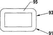
图8是本发明的又一种实施方式的电铸成形的喷嘴组件21的示意图,其中喷嘴组件的形状能够包括组织切割表面91。在该特定的实施方式中,喷嘴组件21的末端区域20包括刮擦装置91。除了刮擦装置91之外,喷嘴组件能够类似于上述组件中的一些,具有远端41,邻近喷射口25的准直喷嘴区域24。液体射流26可以从喷射口25朝着排出管16的射流接收口28发射。在该示例性的实施方式中,刮擦器91具有刃边93和倾斜表面95。如图所示,刮擦器91联接到喷嘴组件21的末端区域20,并且可以通过常规手段例如熔接或铜焊保持在那里。在其他实施方式中,组织切割表面可以与电镀喷嘴组件一体地形成。从刃边93刮离的组织可以被带入射流束26中进行浸渍和去除。FIG. 8 is a schematic illustration of an
通过将金属薄箔放置在适当位置,并且使用它作为形成电沉积层的表面,也可以一体地形成组织切割表面例如刮擦器91。电沉积后加工可以用于精制刃边。A tissue cutting surface such as
除了刮擦器91之外,各种组织操纵器的任何一个可以固定到本发明的器械并且通过该器械携带到手术部位。这些可以不仅包括带有组织切割表面的固定装置,例如刮擦器91,而且包括可以包含组织切割表面的更主动的装置,例如镊子、剪刀式和其他可活动的刀具、牵开器和外科或诊断装置的其他元件,如下面进一步所述。In addition to
在图9中显示了本发明的又一种实施方式。在该实施方式中,将具有末端92的心轴90插入在其中形成U形弯头的压力管94的出口中。该组件用薄导电层涂覆并且然后电镀,形成成形喷嘴组件96的层。喷嘴组件96和心轴末端92可以在C处被切割,以形成在喷嘴组件中的喷射口。然后可以去除心轴90的残余材料,如上所述。在一些实施方式中,也可以提供排出管(未显示)。也可以利用两部分心轴系统,在该方面本发明不受限制。在一些实施方式中,该结构是不太理想的,原因是对于给定的管尺寸它可能具有较大的轮廓。然而,使用一些类型的液体射流外科器械,例如在US2003/0125660中描述的那些,这可能是成形连接到压力管上的预对准喷嘴组件的简单方式。Yet another embodiment of the invention is shown in FIG. 9 . In this embodiment, a mandrel 90 having an end 92 is inserted into the outlet of a pressure tube 94 in which a U-bend is formed. This assembly is coated with a thin conductive layer and then plated, forming the layer that shapes the nozzle assembly 96 . Nozzle assembly 96 and mandrel end 92 may be cut at C to form a jet opening in the nozzle assembly. The remaining material of the mandrel 90 may then be removed, as described above. In some embodiments, a drain (not shown) may also be provided. A two-part mandrel system may also be utilized, as the invention is not limited in this respect. In some embodiments, this structure is less than ideal because it may have a larger profile for a given tube size. However, with some types of liquid jet surgical instruments, such as those described in US2003/0125660, this may be a simple way of shaping a pre-aligned nozzle assembly connected to a pressure tube.
在图9和1的实施方式中,液体射流朝近侧被引导。可以预料射流束的替代方向(未示出),包括远侧末端,其中液体射流朝远侧被引导(例如,与图9中相同,但是没有管中的弯头),或侧向发射射流的末端,即,成除了朝远侧(0度)或近侧180度(图9,图1)之外的某个角,例如大约45度、大约60度、大约75度、大约90度、大约120度,或其他角度。In the embodiment of Figs. 9 and 1, the liquid jet is directed proximally. Alternative directions of the jet stream (not shown) are contemplated, including a distal tip where the liquid jet is directed distally (e.g., the same as in FIG. 9 but without the bend in the tube), or a side-firing jet. The tip, i.e., at some angle other than 180 degrees distally (0 degrees) or proximally (FIG. 9, FIG. 1), such as about 45 degrees, about 60 degrees, about 75 degrees, about 90 degrees, about 120 degrees, or other angles.
图10A和10B示出了根据又一种实施方式用于电铸成形喷嘴组件的第一和第二心轴部分。在该实施方式中,第一心轴部分36类似于上述的第一心轴部分36(例如参见图6A-6C)。第二心轴部分152被成形为具有与第一心轴部分36类似的一些设计特征,原因在于它具有可以安全配合在排出管16内部的部分138,和朝管16的远侧延伸并且由台阶凸缘139定位的部分140。部分140类似于心轴52的部分60(例如参见图5A),并且具有中间孔166,第一心轴36的喷嘴区域46的末端48可以配合在所述中间孔中。与心轴52的情况一样,心轴152可以具有用于清洁碎片的第二孔168。10A and 10B illustrate first and second mandrel sections for an electroformed nozzle assembly according to yet another embodiment. In this embodiment, the
可以使图10A-10B中所示的实施方式在选定点H1的远侧导电,所述点被选择成防止心轴152的部分140的近侧区域的电铸成形,同时允许心轴36和152的剩余暴露部分和管12的远端的电铸成形。在电铸成形喷嘴组件(未示出)之后,可以在点C1和C2处制造切口。在C1处的切口可以去除末端48的近端,这可以形成在喷嘴组件中的喷射口,在C2处的切口可以被制造成稍稍在管16的端部的远侧。心轴的一种或多种材料被去除,并且成品装置可以准备好供使用。The embodiment shown in FIGS. 10A-10B can be made conductive distal to a selected point H1 selected to prevent electroforming of the proximal region of portion 140 of mandrel 152 while allowing
图11示出了另一种实施方式,其中第二心轴部分153能够通过排出管16在排出路径中提供缩窄结构。可以使部件在点H1的远侧导电,这可以允许排出管16的部分的电铸成形。第二心轴部分153可以朝远侧渐缩,并且具有凹痕,例如凹槽180。渐缩可以在电铸成形期间减小第二心轴部分153的近侧区域固定到压力管12上。在电铸成形之后,凹槽180在排出管16的流动路径中提供尺寸限制开孔。FIG. 11 shows another embodiment in which the second mandrel portion 153 is capable of providing a constriction in the discharge path through the
在电铸成形之后,可以在点C1和C2处切割组件。去除心轴的剩余材料。切口导致管16的功能扩展,但是在凹槽180的位置处具有缩窄结构,限制了管16的内腔18的直径。当射流束进入管16时,这可以帮助产生显著的临界压力,所述临界压力帮助排出液体和浸渍存在于装置的使用部位的固体。应当认识到,除了凹槽180之外,其他类型的凹痕,例如但不限于一个或多个窝坑或凹部,也可以形成于第二心轴部分153中,以产生在排出管16中的缩窄结构。After electroforming, the component can be cut at points C1 and C2. Remove remaining material from the mandrel. The incision results in a functional expansion of the
在本发明的又一方面中,可以通过在装置的电铸成形喷嘴组件中制造通道或孔来提供到手术部位的通路。各种常规装置的任何一个可以放置在这样的通道中。在某些实施方式中,当在身体中操作时,这些通道在器械的远侧末端区域通向环境。In yet another aspect of the invention, access to the surgical site may be provided by fabricating channels or holes in the electroformed nozzle assembly of the device. Any of a variety of conventional devices may be placed in such channels. In certain embodiments, these channels open to the environment at the distal tip region of the device when operating in the body.
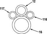
图12B示出了本发明的该特征的一种实施方式。在图12A中显示了联接到排出管16的压力管12的横截面。在图12B中,两个附加管,第一管116和可选的第二管117被加入组件,以形成沿着压力管和/或排出管延伸的两个通道。这些辅助管可以围绕心轴电铸成形,以提供邻近压力管的通道。管116和117可以朝操作电铸成形的喷嘴组件的近侧延伸,并且可以直接或通过与其他管的接头延伸到器械的近端。在一些实施方式中,可以在喷嘴组件的电铸成形期间形成管116和/或117。例如,在一种实施方式中,可以通过用作心轴的材料的固体挤出形成管116、117,在电铸成形之后所述材料可以去除。在一种实施方式中,当用例如不锈钢的预制管形成管116和/或117时,可以在电铸成形过程期间用心轴材料的销(未示出)在它们的远端堵住管。这些销可以朝管的远侧延伸并且可以在电铸成形末端之后被切割,以允许将存在于电铸成形末端中的孔与管116和117连通。Figure 12B illustrates one embodiment of this feature of the invention. A cross-section of the
在另一种实施方式中,管116和/或117可以由圆柱体或可萃取材料的其他细长形状形成。这些可以连接到排出管16和/或压力管12,然后在电铸成形之后,在待去除的远端以与心轴相同的方式,或者通过适合于管116,117的材料的不同程序被充分暴露。In another embodiment,
可以设想各种装置用于由管116、117产生的这些通道。这样的装置包括但不限于用于发射光和/或收集图像的光导纤维;例如驱动连接的装置例如镊子的电缆;用于诊断的探针(pH,pO2,电极等);和电流或电压源,例如电灸探针,或用于其他装置的电力供应。管116、117中的一个或多个通道可以将空气、真空、水、盐水、造影流体或药剂供应到手术部位。这些功能的任何一个可以通过嵌入的管116、117,或者通过向如上所述形成的电铸成形喷嘴组件中的一个或多个孔给送的独立供应被提供。Various means can be envisaged for these passages created by the tubes 116,117. Such devices include, but are not limited to, fiber optics for emitting light and/or collecting images; cables such as actuating connected devices such as tweezers; probes for diagnostics (pH,p02 , electrodes, etc.); and current or voltage sources, such as electromoxibustion probes, or power supplies for other devices. One or more channels in
应当认识到,尽管描述了在管116、117中具有一个或两个通道的实施方式,更多的开孔或管可以被提供,在该方面本发明不受限制。应当认识到,在一些实施方式中,更多的通道可以增加外科器械的轮廓(例如横截面面积)和减小挠性,同时包括通道的管可以弱化末端。因此,在某些实施方式中,通道的数量限于特定外科程序所需的通道的数量。It should be appreciated that although embodiments are described with one or two passages in the
本发明的另一方面涉及使用如上所述制造的创新外科器械对患者执行外科或医疗程序。在一种实施方式中,本发明提供了一种对患者执行医疗或外科程序的方法,所述方法包括将在至少1000psig,在某些情况下至少2000psig,至少5000psig,至少10000psig,至少15000psig,至少30000psig,或至少50000psig的压力下的液体供应给通过如上所述的创新电铸成形方法制造的液体射流外科器械的压力管,用所述器械产生液体射流,和在患者的组织处引导液体射流以切割、消融、粉碎和/或清除组织。在某些这样的实施方式中,所述方法还包括仅仅使用由液体射流生成的临界压力去除液体而不需要应用于排出管的外部抽吸源,所述液体包括液体射流和通过从手术部位到排出管的近端的射流从患者去除的组织。Another aspect of the invention relates to performing a surgical or medical procedure on a patient using the innovative surgical instrument manufactured as described above. In one embodiment, the present invention provides a method of performing a medical or surgical procedure on a patient, the method comprising exposing the blood to a patient at least 1000 psig, in some cases at least 2000 psig, at least 5000 psig, at least 10000 psig, at least 15000 psig, at least Liquid at a pressure of 30,000 psig, or at least 50,000 psig, is supplied to the pressure tube of a liquid jet surgical instrument manufactured by the innovative electroforming process described above, the instrument is used to generate a liquid jet, and the liquid jet is directed at the patient's tissue to Cutting, ablating, pulverizing and/or removing tissue. In certain such embodiments, the method further comprises removing fluid comprising the fluid jet and passing from the surgical site to The proximal end of the expulsion tube ejects the removed tissue from the patient.
尽管在这里描述和示出了本发明的几种实施方式,本领域的普通技术人员将容易预见用于执行功能和/或获得这里所述的结果或优点的各种其他手段和结构,并且每种这样的变化、修改和改进被认为在本发明的范围内。更具体而言,本领域的技术人员将容易理解这里所述的所有参数、尺寸、材料和结构意味着是示例性的,并且实际参数、尺寸、材料和结构将取决于本发明的教导所用于的特定应用。本领域的技术人员将认识到或者能够仅仅使用常规试验确定这里所述的本发明的特定实施方式的许多等同方式。所以,应当理解前述实施方式仅仅作为例子被提出,并且在所附权利要求书及按等同原则确定的范围内,本发明可以以不同于具体所述的另外方式被实施。本发明涉及这里所述的每种个体特征、系统、材料和/或方法。另外,两个或以上这样的特征、系统、材料和/或方法的任何组合被包括在本发明的范围内,只要这样的特征、系统、材料和/或方法不相互矛盾。如这里所限定和使用的所有定义应当被理解成控制字典定义,被引用作为参考的文献中的定义或用法,和/或定义术语的普通含义。Although several embodiments of the present invention have been described and illustrated herein, those of ordinary skill in the art will readily envision various other means and structures for performing the functions and/or obtaining the results or advantages described herein, and each Such variations, modifications and improvements are considered to be within the scope of the present invention. More specifically, those skilled in the art will readily understand that all parameters, dimensions, materials and constructions described herein are meant to be exemplary and that actual parameters, dimensions, materials and constructions will depend on the teachings of the present invention being used specific application. Those skilled in the art will recognize, or be able to ascertain using no more than routine experimentation, many equivalents to the specific embodiments of the invention described herein. It is therefore to be understood that the foregoing embodiments are presented by way of example only, and that within the scope of the appended claims and the doctrine of equivalents, the invention may be practiced otherwise than as specifically described. The present invention is directed to each individual feature, system, material and/or method described herein. In addition, any combination of two or more such features, systems, materials and/or methods is included within the scope of the present invention as long as such features, systems, materials and/or methods are not mutually inconsistent. All definitions, as defined and used herein, should be understood to control over dictionary definitions, definitions or usage in documents cited by reference, and/or ordinary meanings of the defined terms.
也应当理解的是,除非相反地清楚指出,在这里要求保护的包括一个以上步骤或动作的任何方法中,方法的步骤或动作的顺序不一定被限制到叙述所述方法的步骤或动作的顺序。It should also be understood that in any method claimed herein comprising more than one step or action, the order of the steps or actions of the method is not necessarily limited to the order in which the steps or actions of the method are recited, unless expressly stated to the contrary. .
在权利要求中(以及在上面的说明书中),所有过渡短语或包含短语例如“包含”,“包括”,“携带”,“具有”,“含有”,“包括有”,“由...制造”,“由...形成”,“涉及”等,应当被理解成是开放式的,即,表示“包括但不限于”,所以,包含在其后列出的项及其等同项以及附加项。只有过渡短语或包含短语“由...组成”和“基本由...组成”应当分别被理解成封闭式或半封闭式短语。除非清楚指出相反情况,在这里的说明书和权利要求书中使用的不定冠词“一”应当被理解成表示“至少一个”。In the claims (as well as in the specification above), all transitional phrases or inclusion phrases such as "comprises", "comprises", "carries", "has", "comprises", "comprises", "consisting of... Manufactured", "formed by", "relates to", etc., should be understood as open-ended, that is, to mean "including but not limited to", so that the items listed thereafter and their equivalents and Additional items. Only transitional or containing phrases "consisting of" and "consisting essentially of" should be read as closed or semi-closed phrases, respectively. The indefinite article "a" or "a" as used herein in the specification and claims should be understood to mean "at least one" unless clearly indicated to the contrary.
Claims (36)
Translated fromChineseApplications Claiming Priority (2)
| Application Number | Priority Date | Filing Date | Title |
|---|---|---|---|
| US79486706P | 2006-04-25 | 2006-04-25 | |
| US60/794,867 | 2006-04-25 |
Related Child Applications (1)
| Application Number | Title | Priority Date | Filing Date |
|---|---|---|---|
| CN2010105919743ADivisionCN102058424A (en) | 2006-04-25 | 2007-04-25 | Electroformed liquid jet surgical instrument |
Publications (1)
| Publication Number | Publication Date |
|---|---|
| CN101460101Atrue CN101460101A (en) | 2009-06-17 |
Family
ID=38801783
Family Applications (2)
| Application Number | Title | Priority Date | Filing Date |
|---|---|---|---|
| CNA2007800207166APendingCN101460101A (en) | 2006-04-25 | 2007-04-25 | Electroformed liquid jet surgical instrument |
| CN2010105919743APendingCN102058424A (en) | 2006-04-25 | 2007-04-25 | Electroformed liquid jet surgical instrument |
Family Applications After (1)
| Application Number | Title | Priority Date | Filing Date |
|---|---|---|---|
| CN2010105919743APendingCN102058424A (en) | 2006-04-25 | 2007-04-25 | Electroformed liquid jet surgical instrument |
Country Status (6)
| Country | Link |
|---|---|
| US (1) | US20090306692A1 (en) |
| EP (1) | EP2019628A4 (en) |
| KR (1) | KR20090031674A (en) |
| CN (2) | CN101460101A (en) |
| BR (1) | BRPI0710922A2 (en) |
| WO (1) | WO2007142756A1 (en) |
Cited By (11)
| Publication number | Priority date | Publication date | Assignee | Title |
|---|---|---|---|---|
| CN103251440A (en)* | 2012-01-26 | 2013-08-21 | 科维蒂恩有限合伙公司 | Thrombectomy catheter systems |
| CN105125258A (en)* | 2010-03-03 | 2015-12-09 | 精工爱普生株式会社 | FLUID INJECTION DEVICE and surgery apparatus |
| CN106572864A (en)* | 2014-06-30 | 2017-04-19 | 普罗赛普特生物机器人公司 | Fluid jet tissue ablation and coagulation (liquid ablation) methods and devices |
| CN107865683A (en)* | 2016-09-27 | 2018-04-03 | 惠州科赛医疗有限公司 | Nozzle, water knife apparatus, nozzle forming method and water knife apparatus forming method |
| US10588609B2 (en) | 2010-02-04 | 2020-03-17 | Procept Biorobotics Corporation | Gene analysis and generation of stem cell methods and apparatus |
| CN112401972A (en)* | 2020-11-18 | 2021-02-26 | 江苏金泰医疗器械有限公司 | Device for removing thrombus from external water film of catheter |
| CN113795207A (en)* | 2019-06-10 | 2021-12-14 | 新加坡施乐辉亚太有限公司 | Water jet debridement and wound bed preparation |
| US11207058B2 (en) | 2014-09-05 | 2021-12-28 | Procept Biorobotics Corporation | Apparatus for removing intact cells from a surgical site |
| US11213313B2 (en) | 2013-09-06 | 2022-01-04 | Procept Biorobotics Corporation | Tissue resection and treatment with shedding pulses |
| US11406453B2 (en) | 2009-03-06 | 2022-08-09 | Procept Biorobotics Corporation | Physician controlled tissue resection integrated with treatment mapping of target organ images |
| WO2023160315A1 (en)* | 2022-02-28 | 2023-08-31 | 蓝帆外科器械有限公司 | Medical water jet scalpel device and medical water jet scalpel system |
Families Citing this family (43)
| Publication number | Priority date | Publication date | Assignee | Title |
|---|---|---|---|---|
| EP3689274A1 (en) | 2007-02-05 | 2020-08-05 | Boston Scientific Limited | Thrombectomy system |
| US8088163B1 (en) | 2008-02-06 | 2012-01-03 | Kleiner Jeffrey B | Tools and methods for spinal fusion |
| US20210378834A1 (en) | 2008-05-22 | 2021-12-09 | Spinal Surgical Strategies, Inc., A Nevada Corporation D/B/A Kleiner Device Labs | Spinal fusion cage system with inserter |
| USD853560S1 (en) | 2008-10-09 | 2019-07-09 | Nuvasive, Inc. | Spinal implant insertion device |
| US9510854B2 (en) | 2008-10-13 | 2016-12-06 | Boston Scientific Scimed, Inc. | Thrombectomy catheter with control box having pressure/vacuum valve for synchronous aspiration and fluid irrigation |
| US8366748B2 (en) | 2008-12-05 | 2013-02-05 | Kleiner Jeffrey | Apparatus and method of spinal implant and fusion |
| US9717403B2 (en) | 2008-12-05 | 2017-08-01 | Jeffrey B. Kleiner | Method and apparatus for performing retro peritoneal dissection |
| US8864654B2 (en) | 2010-04-20 | 2014-10-21 | Jeffrey B. Kleiner | Method and apparatus for performing retro peritoneal dissection |
| US9247943B1 (en) | 2009-02-06 | 2016-02-02 | Kleiner Intellectual Property, Llc | Devices and methods for preparing an intervertebral workspace |
| USD656610S1 (en) | 2009-02-06 | 2012-03-27 | Kleiner Jeffrey B | Spinal distraction instrument |
| US10973656B2 (en) | 2009-09-18 | 2021-04-13 | Spinal Surgical Strategies, Inc. | Bone graft delivery system and method for using same |
| USD750249S1 (en) | 2014-10-20 | 2016-02-23 | Spinal Surgical Strategies, Llc | Expandable fusion cage |
| US8685031B2 (en) | 2009-09-18 | 2014-04-01 | Spinal Surgical Strategies, Llc | Bone graft delivery system |
| US9173694B2 (en) | 2009-09-18 | 2015-11-03 | Spinal Surgical Strategies, Llc | Fusion cage with combined biological delivery system |
| US9629729B2 (en) | 2009-09-18 | 2017-04-25 | Spinal Surgical Strategies, Llc | Biological delivery system with adaptable fusion cage interface |
| US9186193B2 (en) | 2009-09-18 | 2015-11-17 | Spinal Surgical Strategies, Llc | Fusion cage with combined biological delivery system |
| US20170238984A1 (en) | 2009-09-18 | 2017-08-24 | Spinal Surgical Strategies, Llc | Bone graft delivery device with positioning handle |
| US9060877B2 (en) | 2009-09-18 | 2015-06-23 | Spinal Surgical Strategies, Llc | Fusion cage with combined biological delivery system |
| US10245159B1 (en) | 2009-09-18 | 2019-04-02 | Spinal Surgical Strategies, Llc | Bone graft delivery system and method for using same |
| USD723682S1 (en) | 2013-05-03 | 2015-03-03 | Spinal Surgical Strategies, Llc | Bone graft delivery tool |
| US8906028B2 (en) | 2009-09-18 | 2014-12-09 | Spinal Surgical Strategies, Llc | Bone graft delivery device and method of using the same |
| HK1197964A2 (en) | 2011-12-03 | 2015-02-27 | DePuy Synthes Products, Inc. | Safe cutting heads and systems for fast removal of a target tissue |
| EP3021768B1 (en) | 2013-07-19 | 2020-08-19 | DePuy Synthes Products, Inc. | An anti-clogging device for a vacuum-assisted, tissue removal system |
| US9883877B2 (en) | 2014-05-19 | 2018-02-06 | Walk Vascular, Llc | Systems and methods for removal of blood and thrombotic material |
| US10561440B2 (en) | 2015-09-03 | 2020-02-18 | Vesatek, Llc | Systems and methods for manipulating medical devices |
| USD797290S1 (en) | 2015-10-19 | 2017-09-12 | Spinal Surgical Strategies, Llc | Bone graft delivery tool |
| US10492805B2 (en) | 2016-04-06 | 2019-12-03 | Walk Vascular, Llc | Systems and methods for thrombolysis and delivery of an agent |
| US10492821B2 (en) | 2016-06-24 | 2019-12-03 | Hydrocision, Inc. | Selective tissue removal treatment device |
| US10485568B2 (en) | 2016-06-24 | 2019-11-26 | Hydrocision, Inc. | Selective tissue removal treatment device |
| GB2566947B (en)* | 2017-09-27 | 2021-12-08 | Ge Aviat Systems Ltd | Strut and method of forming strut |
| US11686012B2 (en)* | 2017-10-26 | 2023-06-27 | Unison Industries, Llc | Mandrel for electroforming |
| US11678905B2 (en) | 2018-07-19 | 2023-06-20 | Walk Vascular, Llc | Systems and methods for removal of blood and thrombotic material |
| EP3934558A4 (en) | 2019-03-07 | 2022-12-14 | PROCEPT BioRobotics Corporation | Robotic arms and methods for tissue resection and imaging |
| US11071601B2 (en) | 2019-11-11 | 2021-07-27 | Procept Biorobotics Corporation | Surgical probes for tissue resection with robotic arms |
| US11096753B1 (en) | 2020-06-26 | 2021-08-24 | Procept Biorobotics Corporation | Systems and methods for defining and modifying range of motion of probe used in patient treatment |
| US11877818B2 (en) | 2020-06-26 | 2024-01-23 | Procept Biorobotics Corporation | Integration of robotic arms with surgical probes |
| JP2024506374A (en) | 2021-02-15 | 2024-02-13 | ウォーク バスキュラー, エルエルシー | System and method for removing blood and thrombotic material |
| US12274458B2 (en) | 2021-02-15 | 2025-04-15 | Walk Vascular, Llc | Systems and methods for removal of blood and thrombotic material |
| CN113082342B (en)* | 2021-03-30 | 2022-08-02 | 绵阳美科电子设备有限责任公司 | Disposable pipeline system for cutting or flushing wound surface by adopting high-pressure fluid |
| JP2024515193A (en) | 2021-04-20 | 2024-04-05 | プロセプト バイオロボティクス コーポレイション | Surgical probe with independent energy source - Patents.com |
| CN113662630A (en)* | 2021-08-31 | 2021-11-19 | 蓝帆外科器械有限公司 | Medical water jet scalpel and medical system |
| CN113881986B (en)* | 2021-10-28 | 2025-03-18 | 惠州市本正智能设备有限公司 | Energy-saving nozzles and electroplating equipment |
| EP4613212A1 (en) | 2024-03-07 | 2025-09-10 | Erbe Elektromedizin GmbH | Device and method for superficial cell harvesting |
Family Cites Families (10)
| Publication number | Priority date | Publication date | Assignee | Title |
|---|---|---|---|---|
| DE8426270U1 (en)* | 1984-09-06 | 1985-02-14 | Veltrup, Elmar Michael, Dipl.-Ing., 4150 Krefeld | DEVICE FOR REMOVING SOLID BODIES OR DEPOSITS FROM BODY VESSELS |
| US4715848A (en)* | 1985-04-15 | 1987-12-29 | Beroza Gregory A | Gastro-intestinal lavage system and method |
| CA2048120A1 (en)* | 1990-08-06 | 1992-02-07 | William J. Drasler | Thrombectomy method and device |
| DE4126886A1 (en)* | 1991-08-14 | 1993-02-18 | Hp Medica Gmbh | RINSING CATHETER |
| US5871462A (en)* | 1995-06-07 | 1999-02-16 | Hydrocision, Inc. | Method for using a fluid jet cutting system |
| US6216573B1 (en)* | 1995-06-07 | 2001-04-17 | Hydrocision, Inc. | Fluid jet cutting system |
| US6375635B1 (en)* | 1999-05-18 | 2002-04-23 | Hydrocision, Inc. | Fluid jet surgical instruments |
| US6451017B1 (en)* | 2000-01-10 | 2002-09-17 | Hydrocision, Inc. | Surgical instruments with integrated electrocautery |
| US8162966B2 (en)* | 2002-10-25 | 2012-04-24 | Hydrocision, Inc. | Surgical devices incorporating liquid jet assisted tissue manipulation and methods for their use |
| US7115100B2 (en)* | 2002-11-15 | 2006-10-03 | Ethicon, Inc. | Tissue biopsy and processing device |
- 2007
- 2007-04-25CNCNA2007800207166Apatent/CN101460101A/enactivePending
- 2007-04-25EPEP07809026.3Apatent/EP2019628A4/ennot_activeWithdrawn
- 2007-04-25KRKR1020087028863Apatent/KR20090031674A/ennot_activeWithdrawn
- 2007-04-25BRBRPI0710922-9Apatent/BRPI0710922A2/ennot_activeIP Right Cessation
- 2007-04-25CNCN2010105919743Apatent/CN102058424A/enactivePending
- 2007-04-25WOPCT/US2007/010040patent/WO2007142756A1/enactiveApplication Filing
- 2007-04-25USUS12/298,638patent/US20090306692A1/ennot_activeAbandoned
Cited By (20)
| Publication number | Priority date | Publication date | Assignee | Title |
|---|---|---|---|---|
| US11406453B2 (en) | 2009-03-06 | 2022-08-09 | Procept Biorobotics Corporation | Physician controlled tissue resection integrated with treatment mapping of target organ images |
| US10448966B2 (en) | 2010-02-04 | 2019-10-22 | Procept Biorobotics Corporation | Fluid jet tissue resection and cold coagulation methods |
| US10588609B2 (en) | 2010-02-04 | 2020-03-17 | Procept Biorobotics Corporation | Gene analysis and generation of stem cell methods and apparatus |
| CN105125258A (en)* | 2010-03-03 | 2015-12-09 | 精工爱普生株式会社 | FLUID INJECTION DEVICE and surgery apparatus |
| US9238122B2 (en) | 2012-01-26 | 2016-01-19 | Covidien Lp | Thrombectomy catheter systems |
| CN103251440A (en)* | 2012-01-26 | 2013-08-21 | 科维蒂恩有限合伙公司 | Thrombectomy catheter systems |
| US10064643B2 (en) | 2012-01-26 | 2018-09-04 | Covidien Lp | Thrombectomy catheter systems |
| US10932810B2 (en) | 2012-01-26 | 2021-03-02 | Covidien Lp | Thrombectomy catheter systems |
| CN103251440B (en)* | 2012-01-26 | 2015-08-19 | 科维蒂恩有限合伙公司 | thrombectomy catheter system |
| US11213313B2 (en) | 2013-09-06 | 2022-01-04 | Procept Biorobotics Corporation | Tissue resection and treatment with shedding pulses |
| CN106572864A (en)* | 2014-06-30 | 2017-04-19 | 普罗赛普特生物机器人公司 | Fluid jet tissue ablation and coagulation (liquid ablation) methods and devices |
| US11350963B2 (en) | 2014-06-30 | 2022-06-07 | Procept Biorobotics Corporation | Fluid jet tissue ablation apparatus |
| US12053202B2 (en) | 2014-06-30 | 2024-08-06 | Procept Biorobotics Corporation | Tissue treatment with pulsatile shear waves |
| US12207803B2 (en) | 2014-09-05 | 2025-01-28 | Procept Biorobotics Corporation | Method for removing intact cells from a surgical site |
| US11207058B2 (en) | 2014-09-05 | 2021-12-28 | Procept Biorobotics Corporation | Apparatus for removing intact cells from a surgical site |
| CN107865683A (en)* | 2016-09-27 | 2018-04-03 | 惠州科赛医疗有限公司 | Nozzle, water knife apparatus, nozzle forming method and water knife apparatus forming method |
| WO2018058757A1 (en)* | 2016-09-27 | 2018-04-05 | 惠州科赛医疗有限公司 | Nozzle, water jet scalpel, nozzle molding method, and water jet scalpel molding method |
| CN113795207A (en)* | 2019-06-10 | 2021-12-14 | 新加坡施乐辉亚太有限公司 | Water jet debridement and wound bed preparation |
| CN112401972A (en)* | 2020-11-18 | 2021-02-26 | 江苏金泰医疗器械有限公司 | Device for removing thrombus from external water film of catheter |
| WO2023160315A1 (en)* | 2022-02-28 | 2023-08-31 | 蓝帆外科器械有限公司 | Medical water jet scalpel device and medical water jet scalpel system |
Also Published As
| Publication number | Publication date |
|---|---|
| BRPI0710922A2 (en) | 2012-03-06 |
| WO2007142756A1 (en) | 2007-12-13 |
| CN102058424A (en) | 2011-05-18 |
| US20090306692A1 (en) | 2009-12-10 |
| EP2019628A4 (en) | 2014-03-05 |
| KR20090031674A (en) | 2009-03-27 |
| EP2019628A1 (en) | 2009-02-04 |
Similar Documents
| Publication | Publication Date | Title |
|---|---|---|
| CN101460101A (en) | Electroformed liquid jet surgical instrument | |
| US5921916A (en) | Endoscope utilizing a fiber optic holding tube with a jacket slit for lateral placement of the fiber optic | |
| JP4290013B2 (en) | Endoscope outflow system | |
| JP5866421B2 (en) | Surgical cutting instrument with distal suction function | |
| US20140088577A1 (en) | Devices and methods for laser surgery | |
| JP6661652B2 (en) | RF energy-enabled tissue debridement device | |
| JP5279852B2 (en) | Nozzle assembly for liquid jet surgical instrument and surgical instrument using the nozzle assembly | |
| US12042135B2 (en) | Steerable instrument comprising a radial spacer between coaxial cylindrical elements | |
| CA2326420C (en) | Method of making a tool tip and tool tip | |
| JP2009131650A (en) | Fluid type thrombectomy catheter | |
| WO2018058757A1 (en) | Nozzle, water jet scalpel, nozzle molding method, and water jet scalpel molding method | |
| JP2006204745A (en) | Endoscopic treatment tool | |
| CN113662630A (en) | Medical water jet scalpel and medical system | |
| CN215821086U (en) | Medical water jet scalpel and medical system | |
| NL2028739B1 (en) | Steerable instrument for endoscopic or invasive applications | |
| CN106551788A (en) | Optical Needle with Light Guide Groove | |
| WO2021117649A1 (en) | Biopsy needle and tissue collection device | |
| CN113543746A (en) | Dual spray nozzle tip assembly | |
| CN108065986B (en) | Medical tool bit structure, medical water jet instrument and forming method thereof | |
| WO2018086135A1 (en) | Medical tool bit structure, medical water jet instrument and molding method therefor | |
| CN114098588B (en) | Binocular ureteroscope and manufacturing method thereof | |
| EP3875066A1 (en) | Ophthalmic surgery instrument | |
| CN112773500A (en) | Plasma electric cutting and laser enucleation integrated mirror assembly | |
| JP2006223714A (en) | Endoscope | |
| JP3168428U (en) | Bipolar electrical treatment instrument |
Legal Events
| Date | Code | Title | Description |
|---|---|---|---|
| C06 | Publication | ||
| PB01 | Publication | ||
| C10 | Entry into substantive examination | ||
| SE01 | Entry into force of request for substantive examination | ||
| C02 | Deemed withdrawal of patent application after publication (patent law 2001) | ||
| WD01 | Invention patent application deemed withdrawn after publication | Open date:20090617 |