CN101451678A - Solid lighting device - Google Patents
Solid lighting deviceDownload PDFInfo
- Publication number
- CN101451678A CN101451678ACNA2007102028995ACN200710202899ACN101451678ACN 101451678 ACN101451678 ACN 101451678ACN A2007102028995 ACNA2007102028995 ACN A2007102028995ACN 200710202899 ACN200710202899 ACN 200710202899ACN 101451678 ACN101451678 ACN 101451678A
- Authority
- CN
- China
- Prior art keywords
- light
- solid
- lighting device
- state lighting
- optical
- Prior art date
- Legal status (The legal status is an assumption and is not a legal conclusion. Google has not performed a legal analysis and makes no representation as to the accuracy of the status listed.)
- Pending
Links
- 239000007787solidSubstances0.000titleabstractdescription3
- 230000003287optical effectEffects0.000claimsabstractdescription81
- 238000000605extractionMethods0.000claimsabstractdescription43
- VYPSYNLAJGMNEJ-UHFFFAOYSA-NSilicium dioxideChemical groupO=[Si]=OVYPSYNLAJGMNEJ-UHFFFAOYSA-N0.000claimsdescription7
- 239000000463materialSubstances0.000claimsdescription5
- 239000011521glassSubstances0.000claimsdescription4
- 239000010453quartzSubstances0.000claimsdescription4
- 239000011347resinSubstances0.000claimsdescription4
- 229920005989resinPolymers0.000claimsdescription4
- 239000000741silica gelSubstances0.000claimsdescription3
- 229910002027silica gelInorganic materials0.000claimsdescription3
- 239000000758substrateSubstances0.000claimsdescription3
- -1acrylChemical group0.000claims1
- 230000000694effectsEffects0.000abstractdescription5
- 239000000945fillerSubstances0.000description4
- 229920003229poly(methyl methacrylate)Polymers0.000description4
- 239000004926polymethyl methacrylateSubstances0.000description3
- NIXOWILDQLNWCW-UHFFFAOYSA-Nacrylic acid groupChemical groupC(C=C)(=O)ONIXOWILDQLNWCW-UHFFFAOYSA-N0.000description2
- 229920006397acrylic thermoplasticPolymers0.000description1
- 230000007812deficiencyEffects0.000description1
- 238000005516engineering processMethods0.000description1
- 230000004313glareEffects0.000description1
- 238000005286illuminationMethods0.000description1
- 230000031700light absorptionEffects0.000description1
- 238000000034methodMethods0.000description1
- 230000002093peripheral effectEffects0.000description1
- 229920001296polysiloxanePolymers0.000description1
- 230000005855radiationEffects0.000description1
- 238000001228spectrumMethods0.000description1
- 239000000126substanceSubstances0.000description1
- ISXSCDLOGDJUNJ-UHFFFAOYSA-Ntert-butyl prop-2-enoateChemical compoundCC(C)(C)OC(=O)C=CISXSCDLOGDJUNJ-UHFFFAOYSA-N0.000description1
Images


Classifications
- F—MECHANICAL ENGINEERING; LIGHTING; HEATING; WEAPONS; BLASTING
- F21—LIGHTING
- F21V—FUNCTIONAL FEATURES OR DETAILS OF LIGHTING DEVICES OR SYSTEMS THEREOF; STRUCTURAL COMBINATIONS OF LIGHTING DEVICES WITH OTHER ARTICLES, NOT OTHERWISE PROVIDED FOR
- F21V31/00—Gas-tight or water-tight arrangements
- F21V31/04—Provision of filling media
- F—MECHANICAL ENGINEERING; LIGHTING; HEATING; WEAPONS; BLASTING
- F21—LIGHTING
- F21K—NON-ELECTRIC LIGHT SOURCES USING LUMINESCENCE; LIGHT SOURCES USING ELECTROCHEMILUMINESCENCE; LIGHT SOURCES USING CHARGES OF COMBUSTIBLE MATERIAL; LIGHT SOURCES USING SEMICONDUCTOR DEVICES AS LIGHT-GENERATING ELEMENTS; LIGHT SOURCES NOT OTHERWISE PROVIDED FOR
- F21K9/00—Light sources using semiconductor devices as light-generating elements, e.g. using light-emitting diodes [LED] or lasers
- F21K9/60—Optical arrangements integrated in the light source, e.g. for improving the colour rendering index or the light extraction
- F21K9/68—Details of reflectors forming part of the light source
- F—MECHANICAL ENGINEERING; LIGHTING; HEATING; WEAPONS; BLASTING
- F21—LIGHTING
- F21V—FUNCTIONAL FEATURES OR DETAILS OF LIGHTING DEVICES OR SYSTEMS THEREOF; STRUCTURAL COMBINATIONS OF LIGHTING DEVICES WITH OTHER ARTICLES, NOT OTHERWISE PROVIDED FOR
- F21V13/00—Producing particular characteristics or distribution of the light emitted by means of a combination of elements specified in two or more of main groups F21V1/00 - F21V11/00
- F21V13/02—Combinations of only two kinds of elements
- F21V13/04—Combinations of only two kinds of elements the elements being reflectors and refractors
- F—MECHANICAL ENGINEERING; LIGHTING; HEATING; WEAPONS; BLASTING
- F21—LIGHTING
- F21Y—INDEXING SCHEME ASSOCIATED WITH SUBCLASSES F21K, F21L, F21S and F21V, RELATING TO THE FORM OR THE KIND OF THE LIGHT SOURCES OR OF THE COLOUR OF THE LIGHT EMITTED
- F21Y2103/00—Elongate light sources, e.g. fluorescent tubes
- F21Y2103/30—Elongate light sources, e.g. fluorescent tubes curved
- F21Y2103/33—Elongate light sources, e.g. fluorescent tubes curved annular
- F—MECHANICAL ENGINEERING; LIGHTING; HEATING; WEAPONS; BLASTING
- F21—LIGHTING
- F21Y—INDEXING SCHEME ASSOCIATED WITH SUBCLASSES F21K, F21L, F21S and F21V, RELATING TO THE FORM OR THE KIND OF THE LIGHT SOURCES OR OF THE COLOUR OF THE LIGHT EMITTED
- F21Y2115/00—Light-generating elements of semiconductor light sources
- F21Y2115/10—Light-emitting diodes [LED]
Landscapes
- Engineering & Computer Science (AREA)
- General Engineering & Computer Science (AREA)
- Physics & Mathematics (AREA)
- Microelectronics & Electronic Packaging (AREA)
- Optics & Photonics (AREA)
- Non-Portable Lighting Devices Or Systems Thereof (AREA)
Abstract
Translated fromChinese
Description
Translated fromChinese技术领域technical field
本发明涉及一种固态照明装置,特别涉及一种具有环形出光面的固态照明装置。The invention relates to a solid-state lighting device, in particular to a solid-state lighting device with a ring-shaped light-emitting surface.
背景技术Background technique
目前,具有环形出光面的固态照明装置一般包括一环状的荧光灯管及用以调节该荧光灯管的亮度的一灯罩,该荧光灯管存在耗电、体积大、寿命不长、无法及时启动、需要镇流器才能使光稳定输出、光源会闪烁等不足之处。At present, a solid-state lighting device with a ring-shaped light-emitting surface generally includes a ring-shaped fluorescent tube and a lampshade for adjusting the brightness of the fluorescent tube. The ballast can make the light output stable, the light source will flicker and other deficiencies.
随着科学技术的发展及进步,发光二极管(Light Emitting Diode,LED)因具光质佳(也即光源述出的光谱)及发光效率高等特性而逐渐取代荧光灯管作为照明装置的发光元件,具体可参见Michael S.Shur等人在文献Proceedings of the IEEE,Vol.93,No.10(2005年10月)中发表的“Solid-State Lighting:Toward Superior Illumination”一文。With the development and progress of science and technology, light-emitting diodes (Light Emitting Diode, LED) have gradually replaced fluorescent tubes as light-emitting elements of lighting devices due to their good light quality (that is, the spectrum emitted by the light source) and high luminous efficiency. See the article "Solid-State Lighting: Toward Superior Illumination" published by Michael S. Shur et al. in Proceedings of the IEEE, Vol.93, No.10 (October 2005).
但是,如何将发光元件元件与固态照明装置的其他组件合理搭配,使固态照明装置更具节能的特性,也是业者所面临的一个新的课题。However, how to reasonably match the light-emitting element with other components of the solid-state lighting device to make the solid-state lighting device more energy-saving is also a new issue faced by the industry.
发明内容Contents of the invention
有鉴于此,有必要提供一种节能的具有环形出光面的固态照明装置。In view of this, it is necessary to provide an energy-saving solid-state lighting device with a ring-shaped light-emitting surface.
一种固态照明装置,包括至少一发光元件、一第一光学转向元件、一第二光学转向元件及一环形的光萃取元件,该第一光学转向元件具有一容置腔及位于该容置腔顶端的开口,该光萃取元件环绕该第二光学转向元件且两者均设于该第一光学转向元件的开口处,以封闭该容置腔,该光萃取元件具有设置于该容置腔内的一入光面及与该入光面相对的一出光面,该至少一发光元件位于该容置腔内,并与该第二光学转向元件相对,该至少一发光元件所发出的光经由该第一、第二光学转向元件改变其行进方向至该光萃取元件的入光面,并经由该光萃取元件的出光面射出该固态照明装置。A solid-state lighting device, comprising at least one light-emitting element, a first optical steering element, a second optical steering element, and an annular light extraction element, the first optical steering element has an accommodating cavity and is located in the accommodating cavity The opening at the top, the light extraction element surrounds the second optical diversion element and both are arranged at the opening of the first optical diversion element to close the accommodating cavity, the light extraction element has a A light incident surface and a light exit surface opposite to the light incident surface, the at least one light-emitting element is located in the accommodating cavity, and is opposite to the second optical turning element, the light emitted by the at least one light-emitting element passes through the The first and second optical turning elements change their traveling directions to the light incident surface of the light extraction element, and emit out of the solid state lighting device through the light exit surface of the light extraction element.
与现有技术相比,本发明固态照明装置设有与光源相配合的第一、第二光学转向元件、环形的光萃取元件等结构,光源发出的光经第一光学转向元件及第二光学转向元件反射,并经由光萃取元件传至固态照明装置外,从而尽量避免光被吸收,减少光的耗损,使该固态照明装置具有良好的节能效果。Compared with the prior art, the solid-state lighting device of the present invention is provided with structures such as first and second optical turning elements matched with the light source, and a ring-shaped light extraction element. The light emitted by the light source passes through the first optical turning element and the second optical turning element. The diverting element is reflected and transmitted to the outside of the solid-state lighting device through the light extraction element, so as to avoid light absorption as much as possible and reduce light loss, so that the solid-state lighting device has a good energy-saving effect.
附图说明Description of drawings
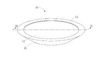
图1为本发明第一较佳实施例的固态照明装置的立体示意图。FIG. 1 is a schematic perspective view of a solid-state lighting device according to a first preferred embodiment of the present invention.
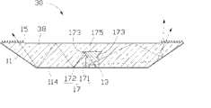
图2为图1所示固态照明装置沿II-II线的剖面示意图。FIG. 2 is a schematic cross-sectional view of the solid-state lighting device shown in FIG. 1 along line II-II.
图3为本发明第二较佳实施例的固态照明装置的剖面示意图。FIG. 3 is a schematic cross-sectional view of a solid-state lighting device according to a second preferred embodiment of the present invention.
图4为本发明第三较佳实施例的固态照明装置的剖面示意图。FIG. 4 is a schematic cross-sectional view of a solid-state lighting device according to a third preferred embodiment of the present invention.
图5为本发明第四较佳实施例的固态照明装置的剖面示意图。FIG. 5 is a schematic cross-sectional view of a solid-state lighting device according to a fourth preferred embodiment of the present invention.
图6为图5所示固态照明装置中光源的立体放大示意图。FIG. 6 is a three-dimensional enlarged schematic view of the light source in the solid-state lighting device shown in FIG. 5 .
图7为本发明第五较佳实施例的固态照明装置的剖面示意图。7 is a schematic cross-sectional view of a solid-state lighting device according to a fifth preferred embodiment of the present invention.
图8为图7所示固态照明装置中光源的立体放大示意图。FIG. 8 is a three-dimensional enlarged schematic view of the light source in the solid-state lighting device shown in FIG. 7 .
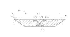
图9为本发明第六较佳实施例的固态照明装置的剖面示意图。FIG. 9 is a schematic cross-sectional view of a solid-state lighting device according to a sixth preferred embodiment of the present invention.
图10为本发明第七较佳实施例的固态照明装置中的光萃取元件外形的平面示意图。10 is a schematic plan view of the shape of the light extraction element in the solid-state lighting device according to the seventh preferred embodiment of the present invention.
图11为本发明第八较佳实施例的固态照明装置中的光萃取元件外形的平面示意图。11 is a schematic plan view of the shape of the light extraction element in the solid-state lighting device according to the eighth preferred embodiment of the present invention.
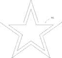
图12为本发明第九较佳实施例的固态照明装置中的光萃取元件外形的平面示意图。12 is a schematic plan view of the shape of the light extraction element in the solid-state lighting device according to the ninth preferred embodiment of the present invention.
具体实施方式Detailed ways
下面参照附图,结合具体实施例对本发明作进一步的描述。The present invention will be further described below in conjunction with specific embodiments with reference to the accompanying drawings.
图1与图2所示为本发明第一较佳实施例的固态照明装置10,该固态照明装置10包括一第一光学转向元件11、一第二转向光学元件12、一光源13及一光萃取元件15。1 and 2 show a solid-
该第一光学转向元件11具有一容置腔114及设于该容置腔114顶端的一开口115,该第一光学转向元件11位于容置腔114内的表面为反射面。The first
该第二光学转向元件12设于该第一光学转向元件11的开口115处,该第二光学转向元件12为圆板状,其位于容置腔114内的表面为反射面,该第二光学转向元件12外径小于该开口115的大小。The second
该光萃取元件15呈环形,其同样设置于该第一光学转向元件11的开口115处,该光萃取元件15环设于该第二光学转向元件12的外围,以封闭该容置腔114。该光萃取元件15由透光材料制成,如硅胶(silicone)、树脂(resin)、玻璃(glass)、压克力(acrylics,化学名称为聚甲基丙烯酸甲酯(polymethyl methacrylate,PMMA))、石英(quartz)等。该光萃取元件15具有位于该第一光学转向元件11的容置腔114内的一入光面151及与该入光面151相对的一出光面152,该出光面152上形成光学微结构,该光学微结构为锯齿形凸远,当光经由该光萃取元件15时,该光萃取元件15的出光面152上的光学微结构,可发散通过该光萃取元件15的光,并使光于出光面152上均匀分布,从而使人眼看起来有雾化的效果而不至于刺眼。当然,该具有光学微结构的出光面152还可为其他形状,如图3所示的本发明第二较佳实施例的固态照明装置20,该固态照明装置20中的光萃取元件25的出光面252的光学微结构为矩形凸远。The
请再参照图2,该光源13设于该第一光学转向元件11的容置腔114内,并与该第二光学转向元件12相对,该光源13包括一发光元件132。该发光元件132的外围罩设一第三光学转向元件17,该第三光学转向元件17为透镜,其包括一本体部171及位于该本体部171上端的一顶部172,该顶部171具有两个相对的倾斜侧面173及相对远离该本体部171的顶面175,该两个倾斜侧面173为透光面,该顶面175为反射面,该本体部171及该顶部172的倾斜侧面173、顶面175共同作用,以用来改变发光元件132发出的光的行进方向。Referring to FIG. 2 again, the
当固态照明装置10工作时,收容于第一光学转向元件11的容置腔114内的发光元件132发出光,一部分光经过第三光学转向元件17的本体部171折射,改变原来的行进方向直接射向第一光学转向元件11及第二光学转向元件12,另一部分光经过第三光学转向元件17的本体部171至顶部172的顶面175,经顶面175反射后由倾斜侧面173折射射出,并改变原来的行进方向至射向第一光学转向元件11及第二光学转向元件12。射向第一光学转向元件11及第二光学转向元件12的光再经过第一光学转向元件11的内表面及第二光学转向元件12的下表面一次或多次反射改变其行进方向,最后沿不同的角度射向该光萃取元件15的入光面151,并经由该光萃取元件15的出光面152传至固态照明装置10外。对于整个固态照明装置10而言,可发光的区域即为该环形的光萃取元件15的部分。When the solid-
与现有技术相比,该固态照明装置10、20设有与光源13相配合的第一光学转向元件11、第二光学转向元件12、第三光学转向元件17及光萃取元件15等结构,使光源13发出的光经第三光学转向元件17的反射及折射,并经由第一光学转向元件11及第二光学转向元件12反射后,最后经由光萃取元件15传至固态照明装置10、20外,从而可尽量避免光被吸收,减少光的耗损,使固态照明装置10、20具有良好的节能效果,同时该光萃取元件15的出光面152具有光学微结构,可使光均匀分布于出光面152上且产生不刺眼的效果。Compared with the prior art, the solid-
图4所示为本发明第三较佳实施例的固态照明装置30的剖面示意图,与本发明第一较佳实施例相比,该固态照明装置30的第一光学元件11内的容置腔114内还填充有填充物38,该填充物38填满容置腔114内含有空气的部分,该填充物38由透光材料制成,如硅胶、树脂、玻璃、压克力、石英等,其折射率与该光萃取元件15及第三光学转向元件17的折射率大致相同,该填充物38的主要作用是减少光行进路径中所经过的界面,从而进一步减少光的耗损。4 is a schematic cross-sectional view of a solid-
当然,上述固态照明装置10、20、30中的光源13的结构还可为其他形式,如以下实施例。Of course, the structure of the
图5与图6所示为本发明第四较佳实施例的固态照明装置40,该光源43包括一圆柱状的基板431及多个发光元件432,这些发光元件432结合于该基板431的圆周侧面上,从而形成一环状的放射光源,使发光元件432产生的光沿侧向方向出射。相比本发明第一至第三较佳实施例的固态照明装置10、20、30的光源13,本实施例中,该光源43上并未设第三光学转向元件,使得本实施例的固态照明装置40仅用到第一、第二光学转向元件,就可达到有效出光的目的。另外,相对单个发光元件,本实施例中的多个发光元件432也使得该环状装置照明40的亮度增加。5 and 6 show a solid-
图7与图8所示为本发明第五较佳实施例的固态照明装置50,该光源53包括多个发光元件532,这些发光元件532均匀排列在一环状的底板533上,在该环状的底板533的中央设有一圆锥状(剖面为三角形)的第三光学转向元件57,该第三光学转向元件57的锥顶设于该底板533的中央,其锥面为一反射面,以改变由该光源53发出的光的行进方向,当然,该圆锥状的第三光学转向元件57也可为透镜,其锥面为透光面,顶面为反射面,其中光的传出的方式与第一较佳实施例中基本相同。另外,该固态照明装置50中的圆锥状的第三光学转向元件57也可为其他形式,如图9所示的本发明第六较佳实施例的固态照明装置60,该固态照明装置60中的第三光学转向元件67包括一中心部671,该中心部671设于该光源53的中央,该中心部671沿远离其肩部方向平滑延伸形成一外围部672,该外围部672靠近发光元件532的表面为反射面,该反射面为圆滑曲面,当然,该反射面也可为平面。7 and 8 show a solid-
另外,上述较佳实施例中,该固态照明装置10、20、30、40、50、60的环形的光萃取元件15(即环形的出光面)的外形不仅限于圆形,如图10所示的第七较佳实施例中,该环形的光萃取元件75的外形为多边形,如图11所示的第八较佳实施例中,该环形的光萃取元件85的外形为十字架形,如图12所示的第九较佳实施例中,该环形的光萃取元件95的外形为星形。上述图10至12所示的第七至九较佳实施例中,该固态照明装置的第一、第二光学转向元件的形状也可对应该光萃取元件75、85、95的外形而改变。In addition, in the above-mentioned preferred embodiments, the shape of the ring-shaped light extraction element 15 (that is, the ring-shaped light-emitting surface) of the solid-
Claims (14)
- [claim 1] a kind of solid-state lighting device, comprise at least one light-emitting component, it is characterized in that: this solid-state lighting device also comprises one first optical inversion element, the light extraction element of one second an optical inversion element and an annular, the opening that this first optical inversion element has a containing cavity and is positioned at this containing cavity top, this light extraction element all is located at the opening part of this first optical inversion element around this second optical inversion element and both, to seal this containing cavity, this light extraction element has an incidence surface and an exiting surface relative with this incidence surface that is arranged in this containing cavity, this at least one light-emitting component is positioned at this containing cavity, and it is relative with this second optical inversion element, the light that this at least one light-emitting component sent via this first, the second optical inversion element changes the incidence surface of its direct of travel to this light extraction element, and penetrates this solid-state lighting device via the exiting surface of this light extraction element.
- [claim 2] solid-state lighting device as claimed in claim 1 is characterized in that: this light extraction element material therefor is silica gel, resin, glass, acryl or quartz.
- [claim 3] solid-state lighting device as claimed in claim 1 is characterized in that: this annular light extraction element is circle, polygon, star or crux.
- [claim 4] solid-state lighting device as claimed in claim 1 is characterized in that: the exiting surface of this light extraction element has optical microstructures.
- [claim 5] solid-state lighting device as claimed in claim 4 is characterized in that: this optical microstructures is that zigzag is protruding far away or rectangle is protruding far away.
- [claim 6] solid-state lighting device as claimed in claim 1 is characterized in that: be filled with light transmissive material in this containing cavity.
- [claim 7] solid-state lighting device as claimed in claim 6 is characterized in that: the refractive index of this light transmissive material is identical with the refractive index of this light extraction element.
- [claim 8] solid-state lighting device as claimed in claim 1 is characterized in that: also comprise the 3rd optical inversion element, the 3rd optical inversion element is located in this containing cavity, and is oppositely arranged with this at least one light-emitting component.
- [claim 9] solid-state lighting device as claimed in claim 8, it is characterized in that: the 3rd optical inversion element covers at described light-emitting component periphery, it comprises a body and is positioned at a top of this body upper end, this top has two opposing inclined sides and relatively away from the end face of this body, the light of injecting the 3rd optical inversion element penetrates via this inclined side.
- [claim 10] solid-state lighting device as claimed in claim 8 is characterized in that: described light-emitting component is a plurality of, and described a plurality of light-emitting components are arranged on the base plate of a ring-type, and the 3rd optical inversion element is located at the central authorities of base plate.
- [claim 11] solid-state lighting device as claimed in claim 10 is characterized in that: the 3rd optical inversion element is coniform, and its vertex of a cone is located at the central authorities of base plate, and the conical surface is a reflecting surface.
- [claim 12] solid-state lighting device as claimed in claim 10 is characterized in that: the 3rd optical inversion element is cone shape lens, and its vertex of a cone is located at the central authorities of base plate, and the conical surface is a transparent surface, and end face is a reflecting surface.
- [claim 13] solid-state lighting device as claimed in claim 10, it is characterized in that: the 3rd optical element has a central part and along an outer part that extends away from the shoulder direction of this central part, this outer part is a reflecting surface near the surface of these a plurality of light-emitting components.
- [claim 14] solid-state lighting device as claimed in claim 1 is characterized in that: described light-emitting component is a plurality of, and described a plurality of light-emitting components are arranged on the circumferential lateral surface of substrate of a column.
Priority Applications (2)
| Application Number | Priority Date | Filing Date | Title |
|---|---|---|---|
| CNA2007102028995ACN101451678A (en) | 2007-12-06 | 2007-12-06 | Solid lighting device |
| US11/967,127US7726848B2 (en) | 2007-12-06 | 2007-12-29 | Solid-state illuminating apparatus |
Applications Claiming Priority (1)
| Application Number | Priority Date | Filing Date | Title |
|---|---|---|---|
| CNA2007102028995ACN101451678A (en) | 2007-12-06 | 2007-12-06 | Solid lighting device |
Publications (1)
| Publication Number | Publication Date |
|---|---|
| CN101451678Atrue CN101451678A (en) | 2009-06-10 |
Family
ID=40721479
Family Applications (1)
| Application Number | Title | Priority Date | Filing Date |
|---|---|---|---|
| CNA2007102028995APendingCN101451678A (en) | 2007-12-06 | 2007-12-06 | Solid lighting device |
Country Status (2)
| Country | Link |
|---|---|
| US (1) | US7726848B2 (en) |
| CN (1) | CN101451678A (en) |
Cited By (2)
| Publication number | Priority date | Publication date | Assignee | Title |
|---|---|---|---|---|
| CN112762409A (en)* | 2019-11-05 | 2021-05-07 | 漳州立达信灯具有限公司 | Lens and lamp |
| WO2022057896A1 (en)* | 2020-09-21 | 2022-03-24 | 苏州欧普照明有限公司 | Lighting lamp and light source system thereof |
Families Citing this family (11)
| Publication number | Priority date | Publication date | Assignee | Title |
|---|---|---|---|---|
| JP5093597B2 (en)* | 2007-03-30 | 2012-12-12 | 日本光電工業株式会社 | Biosignal measurement probe |
| CN101655213A (en)* | 2008-08-21 | 2010-02-24 | 鸿富锦精密工业(深圳)有限公司 | Light-emitting diode light source module |
| JP5212720B2 (en)* | 2008-12-11 | 2013-06-19 | スタンレー電気株式会社 | Lamp |
| CN101907264A (en)* | 2010-06-18 | 2010-12-08 | 海洋王照明科技股份有限公司 | Light distribution structure capable of adjusting projection direction and lamp |
| WO2012042429A2 (en)* | 2010-09-30 | 2012-04-05 | Koninklijke Philips Electronics N.V. | Illumination device and luminaire |
| CN101956919A (en)* | 2010-10-11 | 2011-01-26 | 鸿富锦精密工业(深圳)有限公司 | Light emitting diode lamp |
| US9618678B1 (en)* | 2012-10-23 | 2017-04-11 | Cooper Technologies Company | Waveguide light fixtures |
| JP6002071B2 (en)* | 2013-03-26 | 2016-10-05 | 株式会社東芝 | Illumination device and light guide member |
| CN106164578A (en) | 2014-02-13 | 2016-11-23 | 飞利浦灯具控股公司 | LED illuminator |
| TWI586919B (en)* | 2016-11-04 | 2017-06-11 | 光寶電子(廣州)有限公司 | Lighting device |
| US11346528B2 (en)* | 2019-08-16 | 2022-05-31 | Kenall Manufacturing Company | Lighting fixture having uniform brightness |
Family Cites Families (11)
| Publication number | Priority date | Publication date | Assignee | Title |
|---|---|---|---|---|
| US4587601A (en) | 1981-07-23 | 1986-05-06 | Collins Dynamics, Inc. | Combined flood and spot light incorporating a reflector member of circular and parabolic longitudinal cross section |
| US4920469A (en)* | 1988-11-02 | 1990-04-24 | Harding David K | Light beam amplifier |
| GB9108033D0 (en) | 1991-04-16 | 1991-06-05 | Britax Vega Ltd | Vehicle lamp |
| DE4417695C2 (en) | 1994-05-20 | 1998-01-29 | Reitter & Schefenacker Gmbh | Motor vehicle light |
| DE19644959A1 (en) | 1996-10-29 | 1998-04-30 | Berchtold Gmbh & Co Geb | Operating light |
| JP4181691B2 (en) | 1999-04-30 | 2008-11-19 | スタンレー電気株式会社 | Vehicle lighting |
| JP4235992B2 (en) | 1999-09-01 | 2009-03-11 | スタンレー電気株式会社 | Vehicle lighting |
| US6543911B1 (en) | 2000-05-08 | 2003-04-08 | Farlight Llc | Highly efficient luminaire having optical transformer providing precalculated angular intensity distribution and method therefore |
| US6598998B2 (en) | 2001-05-04 | 2003-07-29 | Lumileds Lighting, U.S., Llc | Side emitting light emitting device |
| KR100631992B1 (en)* | 2005-07-19 | 2006-10-09 | 삼성전기주식회사 | Side-emitting dual lens structure LED package |
| JP2007299599A (en) | 2006-04-28 | 2007-11-15 | Stanley Electric Co Ltd | Ring lamp |
- 2007
- 2007-12-06CNCNA2007102028995Apatent/CN101451678A/enactivePending
- 2007-12-29USUS11/967,127patent/US7726848B2/ennot_activeExpired - Fee Related
Cited By (2)
| Publication number | Priority date | Publication date | Assignee | Title |
|---|---|---|---|---|
| CN112762409A (en)* | 2019-11-05 | 2021-05-07 | 漳州立达信灯具有限公司 | Lens and lamp |
| WO2022057896A1 (en)* | 2020-09-21 | 2022-03-24 | 苏州欧普照明有限公司 | Lighting lamp and light source system thereof |
Also Published As
| Publication number | Publication date |
|---|---|
| US20090147525A1 (en) | 2009-06-11 |
| US7726848B2 (en) | 2010-06-01 |
Similar Documents
| Publication | Publication Date | Title |
|---|---|---|
| CN101451678A (en) | Solid lighting device | |
| RU2544393C2 (en) | Light-emitting device and lighting unit | |
| US9442241B2 (en) | Optics for illumination devices | |
| TWI535978B (en) | Optical lens and lighting element using same | |
| US9534766B2 (en) | Lighting units having light-diffusing optical fiber | |
| KR101948378B1 (en) | Omni-directional reflector comprising a frusto-conical surface for a light-emitting diode | |
| EP2745039B1 (en) | Candle light led light bulbs | |
| CN100595478C (en) | Light emitting device and lens used therefor | |
| TWI537523B (en) | Optical lens and lighting element using the same | |
| CN205244911U (en) | Lighting device and optical member thereof | |
| KR101490065B1 (en) | Lighting apparatus | |
| CN105264288B (en) | Lenses and Lighting Equipment | |
| JP2013084346A (en) | Lighting apparatus | |
| CN204083863U (en) | Lighting device and photoconduction | |
| TWI479107B (en) | Led light distributing lens and light source apparatus using the same | |
| JP6347390B2 (en) | Lighting device | |
| JP2012064558A (en) | Light guide pole uniformly emitting light beam and led lamp applying this light guide pole | |
| CN205037087U (en) | Illuminating device | |
| CN205227197U (en) | Diffuser plate and lamps and lanterns | |
| CN104296068A (en) | Lens for lighting device and lighting device with same | |
| TWI580902B (en) | Light emitting diode light source module | |
| JP3162282U (en) | Light emitting diode | |
| JP5125437B2 (en) | Illumination body | |
| TWM462330U (en) | Light apparatus with curved surface structure | |
| CN104075235A (en) | a surrounding lens |
Legal Events
| Date | Code | Title | Description |
|---|---|---|---|
| C06 | Publication | ||
| PB01 | Publication | ||
| C10 | Entry into substantive examination | ||
| SE01 | Entry into force of request for substantive examination | ||
| C12 | Rejection of a patent application after its publication | ||
| RJ01 | Rejection of invention patent application after publication | Open date:20090610 |