CN101449590A - System and method for removing optical cross-sectional image lines - Google Patents
System and method for removing optical cross-sectional image linesDownload PDFInfo
- Publication number
- CN101449590A CN101449590ACNA2007800186263ACN200780018626ACN101449590ACN 101449590 ACN101449590 ACN 101449590ACN A2007800186263 ACNA2007800186263 ACN A2007800186263ACN 200780018626 ACN200780018626 ACN 200780018626ACN 101449590 ACN101449590 ACN 101449590A
- Authority
- CN
- China
- Prior art keywords
- image
- omega
- output image
- cos
- sin
- Prior art date
- Legal status (The legal status is an assumption and is not a legal conclusion. Google has not performed a legal analysis and makes no representation as to the accuracy of the status listed.)
- Granted
Links
Images


Classifications
- A—HUMAN NECESSITIES
- A61—MEDICAL OR VETERINARY SCIENCE; HYGIENE
- A61B—DIAGNOSIS; SURGERY; IDENTIFICATION
- A61B6/00—Apparatus or devices for radiation diagnosis; Apparatus or devices for radiation diagnosis combined with radiation therapy equipment
- A61B6/52—Devices using data or image processing specially adapted for radiation diagnosis
- A61B6/5258—Devices using data or image processing specially adapted for radiation diagnosis involving detection or reduction of artifacts or noise
- G—PHYSICS
- G01—MEASURING; TESTING
- G01B—MEASURING LENGTH, THICKNESS OR SIMILAR LINEAR DIMENSIONS; MEASURING ANGLES; MEASURING AREAS; MEASURING IRREGULARITIES OF SURFACES OR CONTOURS
- G01B11/00—Measuring arrangements characterised by the use of optical techniques
- G01B11/24—Measuring arrangements characterised by the use of optical techniques for measuring contours or curvatures
- G01B11/25—Measuring arrangements characterised by the use of optical techniques for measuring contours or curvatures by projecting a pattern, e.g. one or more lines, moiré fringes on the object
- G—PHYSICS
- G02—OPTICS
- G02B—OPTICAL ELEMENTS, SYSTEMS OR APPARATUS
- G02B21/00—Microscopes
- G02B21/36—Microscopes arranged for photographic purposes or projection purposes or digital imaging or video purposes including associated control and data processing arrangements
- G02B21/365—Control or image processing arrangements for digital or video microscopes
- G02B21/367—Control or image processing arrangements for digital or video microscopes providing an output produced by processing a plurality of individual source images, e.g. image tiling, montage, composite images, depth sectioning, image comparison
- H—ELECTRICITY
- H04—ELECTRIC COMMUNICATION TECHNIQUE
- H04N—PICTORIAL COMMUNICATION, e.g. TELEVISION
- H04N13/00—Stereoscopic video systems; Multi-view video systems; Details thereof
- H04N13/20—Image signal generators
- H04N13/204—Image signal generators using stereoscopic image cameras
- H04N13/207—Image signal generators using stereoscopic image cameras using a single 2D image sensor
- H—ELECTRICITY
- H04—ELECTRIC COMMUNICATION TECHNIQUE
- H04N—PICTORIAL COMMUNICATION, e.g. TELEVISION
- H04N13/00—Stereoscopic video systems; Multi-view video systems; Details thereof
- H04N13/20—Image signal generators
- H04N13/204—Image signal generators using stereoscopic image cameras
- H04N13/254—Image signal generators using stereoscopic image cameras in combination with electromagnetic radiation sources for illuminating objects
Landscapes
- Engineering & Computer Science (AREA)
- Physics & Mathematics (AREA)
- Multimedia (AREA)
- Computer Vision & Pattern Recognition (AREA)
- Health & Medical Sciences (AREA)
- Life Sciences & Earth Sciences (AREA)
- Optics & Photonics (AREA)
- General Physics & Mathematics (AREA)
- Signal Processing (AREA)
- Medical Informatics (AREA)
- Heart & Thoracic Surgery (AREA)
- Public Health (AREA)
- Radiology & Medical Imaging (AREA)
- Biomedical Technology (AREA)
- Nuclear Medicine, Radiotherapy & Molecular Imaging (AREA)
- Molecular Biology (AREA)
- Surgery (AREA)
- Animal Behavior & Ethology (AREA)
- General Health & Medical Sciences (AREA)
- Pathology (AREA)
- Veterinary Medicine (AREA)
- Electromagnetism (AREA)
- High Energy & Nuclear Physics (AREA)
- Biophysics (AREA)
- Chemical & Material Sciences (AREA)
- Analytical Chemistry (AREA)
- Image Processing (AREA)
- Studio Devices (AREA)
Abstract
Description
Translated fromChinese相关申请的交叉引用Cross References to Related Applications
本申请主张2006年5月22日提出的美国专利申请11/419,566的优先权,其全部内容引用结合于此。This application claims priority to US Patent Application Serial No. 11/419,566, filed May 22, 2006, which is hereby incorporated by reference in its entirety.
技术领域technical field
本发明涉及用于从光学图像的断层去除线条的系统。The invention relates to a system for removing lines from a slice of an optical image.
背景技术Background technique
获得三维对象的二维图像经常是期望的,例如,用于器官研究。对对象成像经常通过显微镜来进行。通过成像三维对象的特定二维平面-切片,则图像的清晰度得到增强。It is often desirable to obtain two-dimensional images of three-dimensional objects, for example, for organ studies. Imaging an object is often performed through a microscope. By imaging a specific two-dimensional plane-slice of a three-dimensional object, the sharpness of the image is enhanced.
传统系统通过多种不同方法产生三维对象内的二维平面的图像,包括去卷积、共焦激光扫描和光学断层(optical sectioning)。对于光学断层,传统系统将格栅图案投影在三维图像内的特定平面,并仅由该格栅图案落在的那些像素来构造图像。该平面是相对于对象来选择的一个平面。待成像对象的平面取决于对象相对于所选择的平面的位移。格栅图案是指改变光强度的图案,其可以绘制成针对像素测量的正弦波,使得峰和最低强度每隔给定数目的像素周期性出现。图1为说明用于执行光学断层的传统系统(例如显微镜)的部件的示意图。灯100发射光,光照射在水平线的格栅102上且随后作为格栅图案被分束器104反射到待成像对象上。由该对象反射的光,包括该格栅图案,随后被相机106捕获为图像。该图像由处理器108处理以产生输出图像。具体而言,处理器108提供仅由格栅图案落在的那些像素构成的输出图像。Conventional systems produce images of two-dimensional planes within three-dimensional objects by a number of different methods, including deconvolution, confocal laser scanning, and optical sectioning. For optical tomography, conventional systems project a grid pattern at specific planes within the three-dimensional image and construct an image from only those pixels where the grid pattern falls. The plane is a plane selected relative to the object. The plane of the object to be imaged depends on the displacement of the object relative to the selected plane. A grid pattern refers to a pattern of varying light intensity that can be plotted as a sine wave measured for pixels such that peaks and minimum intensities occur periodically every given number of pixels. FIG. 1 is a schematic diagram illustrating components of a conventional system, such as a microscope, used to perform optical tomography. The
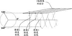
尽管将格栅图案投影在对象上使得可以除去不属于该对象期望平面的那些像素,但是这也在得到的图像中增加了不期望的格栅图案。相应地,格栅102移动到多个位置,在这些位置的每一个得到图像,且这些图像被组合以形成无格栅线的单幅图像。提供压电驱动致动器110以移动格栅102。压电驱动致动器110响应于输入电压。该电压例如可以由处理器108产生。压电驱动致动器110移动格栅102的程度取决于施加到压电驱动致动器110的具体电压。格栅图案的特定强度投影在上面的对象的特定部分,取决于格栅102的位置。压电驱动致动器110被移动以在三个位置之间移动格栅。这些位置设置为使得所得到的相应格栅图案的强度可以绘制成相应正弦波,其中该正弦波内特定点在该三个格栅图案之间被相移相同相位角,即,0度、120度和240度的相位角,每个分隔120度。对于格栅102的三个位置的每一个,相机106捕获相应图像。图2示出相互叠加的3幅图像及其相应格栅线强度曲线。Although projecting a grid pattern onto an object makes it possible to remove those pixels that do not belong to the desired plane of the object, it also adds an undesired grid pattern to the resulting image. Accordingly, grid 102 is moved to a plurality of positions, images are taken at each of these positions, and the images are combined to form a single image without grid lines. A piezo-driven
对于每个像素,处理器108使用公式

为了保证施加到压电驱动致动器110的电压将致使压电驱动致动器110把格栅102移动正确量(此时格栅图案相移120度),某些或所有传统系统需要校准。对于校准,具有大致上均匀表面的对象,例如平滑镜子,作为待成像对象被插入,且如上所述捕获三幅图像。如果相位不正确,伪影出现在组合图像内,其中该伪影为格栅图案频率的谐波。相应地,施加到压电驱动致动器110的电压,且因此相位,被反复改变。对于每一改变,记录三幅图像,且通过快速傅立叶变换(FFT)来测量组合图像内的伪影的信号功率。这些改变被重复,直到该信号功率确定为小于特定阈值,表明伪影的基本除去,这对应于近似正确的相移。一旦得到近似正确的相移,校准完成。To ensure that voltage applied to piezo-driven
该过程需要组合每组三幅图像的像素值,用于进行伪影分析。该过程通常花45秒,但是可长达5分钟。此外,相位角不是直接确定。相反,得到的是近似对应于图像位于期望相位角的情形的相位角,即,低于伪影信号阈值的减小。该过程无法精确得到期望相位角。此外,伪影信号低于阈值的情形无法使用FFT来精确地确定,特别是考虑FFT低的精确度,这至少部分可归因于以离散值测量信号功率。因此,未完全从图像除去格栅线和/或伪影。This process requires combining pixel values from each set of three images for artifact analysis. The process typically takes 45 seconds, but can take as long as 5 minutes. Furthermore, the phase angle is not directly determined. Instead, what is obtained is a phase angle that approximately corresponds to the situation where the image is at the desired phase angle, ie a reduction below the threshold of the artifact signal. This process cannot accurately obtain the desired phase angle. Furthermore, situations where the artifact signal is below the threshold cannot be accurately determined using the FFT, especially considering the low accuracy of the FFT, which is at least in part attributable to measuring the signal power in discrete values. Therefore, gridlines and/or artifacts are not completely removed from the image.
此外,就图像强度值而言,由相机106返回的像素值经常不精确。相应地,伪影的强度的测量经常不准确。压电驱动致动器110因此被不准确地校准。Furthermore, the pixel values returned by the
再者,与校准过程的精确度无关地,通过组合三幅图像得到的输出图像经常包含伪影。伪影经常为与格栅图案类似的图像强度的正弦变化。尽管伪影的正弦变化不一定与格栅图案频率相同,但是其通常是格栅图案的产物且位于格栅图案的正弦波的某个谐波。伪影存在诸多可能起因。示例性起因为例如压电驱动致动器110的部件的未对准,这导致图像的像素值之间的强度变化(而非格栅图案本身导致的强度变化)。这种强度变化导致三幅图案在组合时格栅图案并不抵消。其它因素也对伪影产生贡献。Furthermore, regardless of the accuracy of the calibration process, the output image obtained by combining the three images often contains artifacts. Artifacts are often sinusoidal variations in image intensity similar to grid patterns. Although the sinusoidal variation of the artifact is not necessarily at the same frequency as the grid pattern, it is usually a product of the grid pattern and lies at some harmonic of the grid pattern's sine wave. There are many possible causes of artifacts. An exemplary cause is misalignment of components such as
此外,尽管组合三幅图像可以除去格栅线,但是该过程不产生最优图像。Furthermore, although combining the three images can remove the grid lines, this process does not produce an optimal image.
相应地,本领域需要一种系统和方法,用于有效地校准格栅102的移动并提供无格栅线或伪影的最优图像。Accordingly, what is needed in the art is a system and method for efficiently calibrating the movement of the grid 102 and providing an optimal image free of grid lines or artifacts.
发明内容Contents of the invention
本发明的实施例涉及,通过确定连续地投影在待成像对象上的格栅图案的相位角,经由光学断层来产生图像的设备、计算机系统和方法。本发明的实施例涉及基于格栅图案的相位角来产生图像的设备、计算机系统和方法,其中格栅图案的相位角是参照为实际记录像素值的对数值或近似对数像素值的像素值来设置或确定的。本发明的实施例涉及基于多幅图像的值来产生图像的设备、计算机系统和方法,该图像包含超过三幅图像组合,特别是其中该多幅图像的每对连续图像中的图像是以不同相位角来得到的,即,每一幅图像的相位角均与其前一幅图像不同。此处使用的连续图像是指就格栅图案相位角而言是连续的,而非记录时间上的连续。本发明的实施例涉及从通过光学断层产生的输出图像除去伪影的设备、计算机系统和方法。Embodiments of the invention relate to devices, computer systems and methods for generating images via optical tomography by determining the phase angle of a grating pattern successively projected onto an object to be imaged. Embodiments of the invention relate to devices, computer systems, and methods for generating images based on the phase angle of a grid pattern, wherein the phase angle of the grid pattern is referenced to a pixel value that is a logarithmic or approximately logarithmic pixel value of an actual recorded pixel value to set or determine. Embodiments of the invention relate to apparatus, computer systems and methods for generating an image based on the values of a plurality of images, the image comprising more than three image combinations, in particular wherein the images in each pair of consecutive images of the plurality of images are in different The phase angle is obtained, that is, the phase angle of each image is different from that of the previous image. Sequential images as used herein means continuous in terms of grid pattern phase angles, not continuous in recording time. Embodiments of the invention relate to apparatus, computer systems and methods for removing artifacts from output images produced by optical tomography.
该计算机系统可包含以任何传统计算机语言写入的计算机程序。可用于实施本发明的计算机系统和方法的示例性计算机语言可以为C和/或MATLAB。The computer system may contain computer programs written in any conventional computer language. Exemplary computer languages that may be used to implement the computer systems and methods of the present invention may be C and/or MATLAB.
附图说明Description of drawings
图1为说明用于执行光学断层的传统成像系统的部件的框图。FIG. 1 is a block diagram illustrating components of a conventional imaging system for performing optical tomography.
图2说明传统系统内记录的三幅图像的叠加及其相应格栅图案强度。Figure 2 illustrates the superposition of three images recorded in a conventional system and their corresponding grid pattern intensities.
图3为说明本发明示例性实施例的成像系统的示例性部件的框图。FIG. 3 is a block diagram illustrating exemplary components of an imaging system according to an exemplary embodiment of the present invention.
图4为说明本发明示例性实施例的用于产生光学断面图像(optical section image)的过程的流程和数据流图。FIG. 4 is a flowchart and data flow diagram illustrating a process for generating an optical section image according to an exemplary embodiment of the present invention.
图5说明本发明示例性实施例的用于确定输出图像像素值的,像素值的同相及正交分量与输出像素值的关系。5 illustrates the relationship between the in-phase and quadrature components of a pixel value and the output pixel value for determining an output image pixel value according to an exemplary embodiment of the present invention.
图6为说明本发明示例性实施例的用于产生光学断面图像的第二过程的流程和数据流图。FIG. 6 is a flow and data flow diagram illustrating a second process for generating an optical cross-sectional image according to an exemplary embodiment of the present invention.
图7说明一示例性成像区域,该成像区域具有对同一像素行产生不同影响的格栅图案。FIG. 7 illustrates an exemplary imaging region with a grid pattern that affects the same row of pixels differently.
图8说明本发明示例性实施例的可用于确定格栅图案倾斜的频率集。Figure 8 illustrates a set of frequencies that may be used to determine the tilt of a grid pattern according to an exemplary embodiment of the present invention.
图9说明分量r、a、b和相位角的关系,其中a和b分别为幅值的余弦和正弦分量。Figure 9 illustrates the relationship between the components r, a, b and the phase angle, where a and b are the cosine and sine components of the magnitude, respectively.
图10说明本发明示例性实施例的用于产生输出图像的超过三幅图像的相位角。Figure 10 illustrates the phase angles of more than three images used to generate an output image according to an exemplary embodiment of the present invention.
图11a和11b示出未变换图像和本发明实施例的变换图像的图像强度正弦变化之间的差异。Figures 11a and 11b show the difference between the sinusoidal variation in image intensity of an untransformed image and a transformed image of an embodiment of the invention.
图12为说明本发明示例性实施例的通过减去代表伪影的正弦波来除去伪影的过程的流程。FIG. 12 is a flowchart illustrating a process of removing an artifact by subtracting a sine wave representing the artifact according to an exemplary embodiment of the present invention.
图13为说明本发明示例性实施例的通过修正图像压缩数据来除去伪影的过程的流程。FIG. 13 is a flowchart illustrating a process of removing artifacts by correcting image compression data according to an exemplary embodiment of the present invention.
图14为包括通过光学断层产生的伪影的示例性图像。FIG. 14 is an exemplary image including artifacts produced by optical tomography.
图15为依据本发明示例性实施例可产生的示例性压缩图像。Fig. 15 is an exemplary compressed image that may be generated according to an exemplary embodiment of the present invention.
图16为本发明示例性实施例的通过从光学断面图像除去伪影可产生示例性图像。FIG. 16 is an exemplary image that can be generated by removing artifacts from an optical cross-sectional image according to an exemplary embodiment of the present invention.
具体实施方式Detailed ways
直接计算相位角Calculate the phase angle directly
图3说明本发明实施例的成像系统的部件。图3中参考图1在上文所述的部件使用相同的参考符号。参考图3,在本发明实施例中,为了获得对象的图像,格栅102可以通过压电驱动致动器110移动到三个不同位置。将理解,可以使用压电驱动致动器以外的致动器。每个位置可处于不同相位角。对于该三个位置的每一个,相机106,例如CCD(电荷耦合装置)相机或其他传统相机,可以记录包括格栅线的相应图像。处理器108可以基于三幅记录图像产生输出图像,该处理器可以是任何恰当合适的计算机处理器或其等同物。处理器108可以是任何恰当合适的计算装置,例如计算机、个人数字助理(PDA)、膝上型计算机、笔记本计算机、移动电话、基于硬盘的装置、或者可以接收、发送和存储数据的任何装置。Figure 3 illustrates components of an imaging system of an embodiment of the invention. Components in FIG. 3 that were described above with reference to FIG. 1 use the same reference symbols. Referring to FIG. 3 , in an embodiment of the present invention, grid 102 can be moved to three different positions by piezo-driven
可使用三个格栅位置和相应图像,以便基于与偏移120°的格栅相位角对应的图像而产生输出图像。备选地,三个格栅位置和相应图像即使未偏移120°,仍可用于为每个像素提供三个方程,每幅图像一个方程。每个方程可包括与像素值的分量相对应的三个未知变量。每个方程可以是In=Iw+Iccosφn+Issinφn,其中In代表三幅图像中的特定图像n的像素值,Iw代表像素值的广视野分量,φn代表特定图像n的相位角,Ic代表同相分量,以及Is代表正交分量。如果三幅图像的相应相位角确定,则由于为仅三个未知数提供了三个方程,因此可以计算得到未知数Iw、Ic和Is的值。Three grid positions and corresponding images may be used to generate an output image based on images corresponding to grid phase angles offset by 120°. Alternatively, the three grid positions and corresponding images, even if not offset by 120°, can still be used to provide three equations for each pixel, one equation per image. Each equation may include three unknown variables corresponding to the components of the pixel value. Each equation can beIn = Iw + Ic cos φn + Is sin φn , where In represents the pixel value of a specific image n among the three images,I wrepresents the wide-field component of the pixel value, and φn represents For the phase angle of a particular image n, Ic represents the in-phase component, and Is represents the quadrature component. If the corresponding phase angles of the three images are determined, the values of the unknowns Iw , Ic and Is can be calculated since three equations are provided for only three unknowns.
对于所记录的图像中的每一个,该系统可确定该图像的相位角,其中处理器108基于所记录的图像的组合而产生输出图像。就此而言,处理器108可将这些图像之一例如这些图像的第一幅指定为0°相位角,而不管相应格栅位置,这是因为相位角可对应于图像之间相位偏移,而不考虑格栅线相对于外部对象的移动,即,图像相位相对于彼此被测量。处理器108随后计算其余图像的各自相位角,该相位角表示与被指定为0°相位角的图像的相位之间的相位偏移。为了确定相位角,可以拍摄从大致上均匀表面反射的光的图像。例如,如果待成像的对象不具有大致上均匀表面,为了确定相位角,则需要将具有大致上均匀表面的不同对象插入相机的视线内。For each of the recorded images, the system may determine the phase angle of the image, wherein the
在本发明实施例中,处理器108可校准致动器110以移动格栅102,以使得相位角设置为预定相位角,例如0°、120°和240°的相位角。为了校准致动器110,处理器108可致使相机106反复地记录图像集。对于该图像集中的每幅图像,处理器108可分别确定相应图像相位角并将其与预定相位角比较。基于所确定的实际相位角与预定相位角之间的偏差,处理器108可输出新电压值;依据该新电压值,电压被施加到致动器110以移动格栅102。该循环(即,施加电压到致动器110,捕获图像集,分别确定该图像集中的图像的相位角,将所确定的相位角与预定相位角比较,以及输出新电压值),可以反复地执行,直至所确定的实际相位角在预定容差范围内与该预定相位角匹配。如果存在匹配,处理器108可终止该校准而不改变电压值。该校准可以快速地执行,因为对于每个循环,由相机106记录的图像的相位角可以直接确定。In an embodiment of the invention, the
在校准之后,处理器108例如响应于使用者指令,通过致使相机106记录三幅图像并根据公式
图4为说明本发明实施例的用于获得图像的过程的流程,该过程例如可以由如图4标题所示的处理器108、相机106和致动器110来执行。例如,通过执行作为计算机可执行指令而存储于处理器108内的计算机可读取介质、存储器312、或者本领域普通技术人员已知的成像系统的任何其他部分内的算法、软件或者方程,可以执行图4、6、12和13的过程。该计算机可读取介质可包括软盘、光盘、数字视频盘、计算机盘只读存储器(CD-ROM)等。在400,校准过程开始。在402,处理器108指示相机106记录例如三幅图像的图像集。在404,相机开始图像集的记录。在图像集的图像记录之间,处理器108在406可致使施加电压到压电驱动致动器110。响应于该电压,致动器110在408可移动格栅102。在图像记录之后,相机106在410可将记录的图像传输到处理器108。将理解,相机106可在每幅图像的记录之后传输每幅图像,或者通过单一批次传递来传输这些图像。在414,处理器108可分别确定每幅图像的图像相位角。如果处理器在416确定相位角未偏移120°,则处理器108可继续该校准过程。否则,处理器108在418结束该校准过程。FIG. 4 is a flowchart illustrating a process for obtaining an image according to an embodiment of the present invention, which may be performed, for example, by the
在校准之后,例如响应于使用者指令,处理器108在420开始针对输出图像的图像产生过程。对于该图像产生过程,最初可执行402-410。如果待成像对象提供足够数据以确定图像相位角,则402-410的再次执行可以省略。就此而言,如果待成像对象本身具有均匀表面,例如镜子,则可使用待成像对象来执行校准。相应地,处理器108可使用在校准过程中使用的图像数据用于该图像产生过程。此外,即使待成像对象具有非均匀表面,也有可能从对象的图像得到的数据对于校准过程是足够的。通过计算每幅图像的角频率(在下文详述)和相位角,可以比较计算结果。如果结果大致上匹配,则假定该对象已经提供足够的数据,即,对具有特定性能的校准片(calibration slide)的成像可以省略。由于待成像对象经常未提供足够数据用于确定相位角,指定对象的分别记录可被执行用于相位角确定。随后,在422,处理器108可将公式
在本发明备选实施例中,校准可省略。根据该实施例,处理器108可致使相机记录具有大致上均匀表面的对象的单个图像集以确定由格栅102移动导致的图像的相位角。处理器108可将所确定的相位角保存在存储器312内。备选地,如果待成像对象具有均匀表面或者包括大量细节使得可以从对象图像获得大量数据,则处理器108可根据待成像对象的图像来确定图像相位角,而不预先成像另一对象,其中该另一对象插入到相机的视线内仅用于确定相位角。In alternative embodiments of the invention, calibration may be omitted. According to this embodiment, the
在将所确定的相位角保存在存储器312内之后,例如响应于使用者指令,通过致使相机106记录三幅图像并将输出图像的每个像素的值设置为将所保存的相位角代入方程矩阵并求解像素值的Ic和Is分量而得到的值,处理器108产生对象的输出图像。如上所述,对于该三幅图像的每一幅,特定像素值为In=Iw+Iccosφn+Issinφn。相应地,特定像素可定义为:After saving the determined phase angles in
该方程矩阵可以如下重写以求解变量Iw、Ic和Is:This equation matrix can be rewritten as follows to solve for the variablesIw ,Ic andIs :
一旦计算得到Ic和Is,处理器108可确定输出图像的像素值Ip,因为Ic和Is为像素值Ipi的同相和正交聚焦(in focus)分量,如图5所示(IW为广视野图像)。处理器108可根据公式
图6为说明本发明该实施例的用于获得图像的过程的流程,该过程例如可以由图4标题所示的处理器108、相机106和致动器110来执行。图6中的参考图4在上文所述的部件使用相同的参考符号。根据本实施例,不执行校准。相反,仅执行相位角确定过程。400和418因此用600和618替代,且416的确定不执行。对于420,如上所述,如果待成像图像提供足够数据以确定图像相位角,402-410的再次执行可以省略。此外,由于根据本实施例并不执行用于获得偏移120°的相位角的校准,422被522替代,其中在522应用公式
将理解,即使根据不执行校准过程的本实施例,处理器108可使用公式
相应地,通过确定三幅图像的相位角,可以快速地执行校准。此外,通过确定相位角,可以基于处于不同相位角的图像的集合来产生输出图像,即使不校准致动器110以致使该图像集的图像的格栅线位于预定相位角。Accordingly, by determining the phase angles of the three images, calibration can be performed quickly. Furthermore, by determining the phase angle, an output image can be generated based on a set of images at different phase angles, even without calibrating the
参考图4和6,在本发明实施例中,处理器108可在412确定该图像集的图像的格栅线的角频率,并可以基于图像的像素值与所确定的频率的关联来计算该图像集的图像的相位角,如下所述。具体参考图4,尽管在本发明一个实施例中,可通过比较所确定的频率在用于质量控制的校准过程的每次迭代期间执行412,但是在备选实施例中,在校准过程的除了第一次迭代的每次迭代期间可以省略412,因为一旦频率已知,就无需重新计算。将理解,频率不被固定。例如,频率可依赖于反射图像或者反射到对象上的光的放大倍数,该放大倍数可取决于透镜的位置。为了通过像素值与所确定频率的关联来计算相位角,需要高度精确地确定频率。例如,使用FFT对于频率的确定可能是不够的。在本发明示例性实施例中,处理器108可使用贝叶斯频谱分析(Bayesian Spectral Analysis)高精度地估计频率,本领域技术人员公认的是,贝叶斯频谱分析这种分析提供了比使用FFT获得的离散值结果更为流畅的结果。4 and 6, in an embodiment of the present invention, the
为了应用贝叶斯频谱分析,可以收集图像的信号数据。每个信号可以使用与图像强度的正弦变化相关的方程来表述。该方程可以是f(yi)=rcos(ωyi+φ)+c,其中r为幅值,ω为所确定的角频率,y为像素位置,φ为相位角,以及c为图像强度的平均值。关于y,将理解,其可以是沿垂直方向或者沿水平方向的像素坐标,取决于格栅线的取向。例如,格栅102的取向可以使得格栅线水平地投影在图像上,由此导致沿垂直方向的图像强度变化。在这种情形下,像素坐标为沿垂直方向的像素坐标。图像强度的正弦变化也可以用f(yi)=acosωyi+bsinωyi+c表示,其中a和b为幅值的余弦和正弦分量。尽管前述两个方程是等价的,前一个方程仅包含两个未知数ω和φ,而后一个方程仅包含这两个未知数之一,即ω。相应地,使用后一个公式,例如通过下述方式通过贝叶斯频谱分析可以确定角频率ω。In order to apply Bayesian spectral analysis, signal data of an image can be collected. Each signal can be expressed using an equation related to the sinusoidal variation in image intensity. The equation can be f(yi )=rcos(ωyi +φ)+c, where r is the magnitude, ω is the determined angular frequency, y is the pixel position, φ is the phase angle, and c is the ratio of the image intensity average value. Regarding y, it will be understood that it may be a pixel coordinate in the vertical direction or in the horizontal direction, depending on the orientation of the grid lines. For example, the grid 102 may be oriented such that grid lines are projected horizontally on the image, thereby causing image intensity variations in the vertical direction. In this case, the pixel coordinates are pixel coordinates in the vertical direction. The sinusoidal variation of image intensity can also be represented by f(yi )=acosωyi +bsinωyi +c, where a and b are the cosine and sine components of the amplitude. Although the preceding two equations are equivalent, the former contains only two unknowns, ω and φ, while the latter contains only one of these two unknowns, namely ω. Accordingly, using the latter formula, the angular frequency ω can be determined, for example, by Bayesian spectral analysis in the following manner.
将后一个公式应用到多个数据样本‘d’,可以得到下述矩阵表述:Applying the latter formula to multiple data samples 'd' leads to the following matrix representation:
因此可以得到一矩阵,其中:So a matrix can be obtained, where:
可以积分(integrate out)得到线性系数和噪声标准偏差。然后通过将G矩阵应用到贝叶斯公式
在本发明一个示例性实施例中,图像的窄条可以用作数据源,而不是整幅图像。例如,如果格栅线水平地投影在图像上,导致沿垂直方向的图像强度变化,图像的垂直条可用作数据源。尽管与使用整幅图像相比,使用窄条提供更少的数据用于输入到方程内,但是这可以增加精确度,因为格栅线可以相对于成像区域成角度地投影,由此使数据输入歪斜,如下文所详述。In an exemplary embodiment of the invention, a narrow strip of an image may be used as a data source rather than the entire image. For example, if the grid lines are projected horizontally on the image, resulting in variations in image intensity along the vertical direction, the vertical strips of the image can be used as a data source. Although using narrow bars provides less data to enter into the equations than using the entire image, it can increase accuracy because the gridlines can be projected at an angle relative to the imaged area, thereby making the data input Skew, as detailed below.
在本发明备选实施例中,对于用作输入到贝叶斯频谱分析的数据,可以使用所有的图像像素的值。In an alternative embodiment of the invention, the values of all image pixels may be used for data used as input to Bayesian spectral analysis.
在又一实施例中,可以对每一像素行(或者像素列,如果格栅线垂直投影)求和。每行的像素值和
然而,关于后两个实施例,如果格栅102置为使得格栅线相对于成像区域成角度投影,则由投影格栅图案导致的图像强度的正弦变化将不等地影响沿同一行的像素,如上所述。图7说明这种现象。图7示出格栅图案702成角度地投影在其上的成像区域700。对于选定行704,格栅图案702不同地影响行704的不同像素的值。例如,尽管像素2示为未受影响,但是像素13显示为受很大影响。相应地,如果选定行704的像素值被求和或者以其他方式组合用作频率确定的数据输入,所得到的频率值可能不正确。However, with respect to the latter two embodiments, if the grid 102 is positioned such that the grid lines are projected at an angle relative to the imaging area, the sinusoidal variation in image intensity caused by the projected grid pattern will affect pixels along the same row unequally , as above. Figure 7 illustrates this phenomenon. FIG. 7 shows an
因此,在本发明示例性实施例中,在确定格栅图案的频率之前,图像可被旋转使得格栅图案平行于成像区域的横坐标(或者平行于纵坐标,如果格栅线垂直投影)。格栅线相对于横坐标投影的角度(α)可确定,且图像可旋转-α。Therefore, in an exemplary embodiment of the invention, prior to determining the frequency of the grid pattern, the image may be rotated such that the grid pattern is parallel to the abscissa of the imaging area (or parallel to the ordinate, if the grid lines are projected vertically). The angle (α) of the grid lines relative to the abscissa projection can be determined, and the image can be rotated by -α.
在本发明实施例中,格栅线相对于成像区域的横坐标投影的弧度角可以如下确定:(a)确定格栅图案沿两个任意对角线的频率,所述对角线叠加在图像上且相对于成像区域的横坐标以相反的角度45°和-45°布置,以及(b)将所确定的频率应用到公式

例如,图8示出相对于成像区域700的横坐标在45°角绘制的对角线801和在-45°角绘制的对角线802。当格栅图案成角度布置时,格栅线的实际频率可能不同于沿对角线得到的频率。此外,沿两个对角线得到的频率会不同。例如,沿实际频率线800得到的格栅线频率代表图8中的实际格栅频率,约为图8的测量单位的0.5603。然而,沿对角线801和802测量的格栅线频率分别约为测量单位的1.1420和0.6402。For example, FIG. 8 shows a
将这些频率应用到

注意,图8示出对角线801和802以及实际频率线800的格栅线周期。然而,通过2π/周期将周期转换成角频率得到相同结果。例如,对于周期1.1420,角频率为5.50191358,以及对于周期0.6402,角频率为9.81441004。将这些频率的周期代入方程
一旦倾斜得到校正,该系统和方法可以按照上述方式确定格栅线频率。Once the tilt is corrected, the system and method can determine the grid line frequency as described above.
一旦频率确定,则图像的相位角可以确定。对于图像的像素值,acosωyi+bsinωyi+c的a和b分量可以通过使用像素值到所确定频率的线性回归来估计。一旦a和b被估计,图像的相位角可以根据图9所示的关系而计算为arctan(b/a)。可以进行任意单个图像的相位角的确定而不使用与图像集中的其他图像有关的数据。例如,参考图4和6,只要从相机106接收到图像即可执行412和414,即使相机106在每幅图像的记录之后分别立即传输该图像。相应地,在致动器110移动格栅102以准备记录后一图像和/或当相机106记录后一图像时,处理器108可对先前接收的图像执行412和414。Once the frequency is determined, the phase angle of the image can be determined. For pixel values of an image, the a and b components of acosωyi +bsinωyi +c can be estimated by using linear regression of the pixel values to the determined frequencies. Once a and b are estimated, the phase angle of the image can be calculated as arctan(b/a) according to the relationship shown in FIG. 9 . The determination of the phase angle for any single image can be done without using data related to other images in the set of images. For example, with reference to Figures 4 and 6, 412 and 414 may be performed whenever an image is received from
使用超过三幅图像Use more than three images
如上所详述,通过基于图像集的相应像素值的组合确定像素值,可以执行图像产生过程,其中对于每一图像,格栅线以不同相位角被投影。尽管用于产生输出图像的图像集通常包含三幅图像,在本发明实施例中,为了获得更好质量图像,处理器108可以基于超过三幅图像的像素值来产生输出图像。例如,相位角之间的偏移可以减小,如图10所示。图10示出图像之间偏移30°相位角。为了清楚,仅示出单幅图像即参考图像的强度曲线。虚线表示其余图像强度曲线的开始。根据本实施例,矩阵公式
如上所述确定相位角,超过三幅图像的图像集提供了比未知数多的方程,因为仅Iw、Ic和Is是未知数。由于噪声,这些方程可能不完全一致。相应地,例如最小二乘方回归的回归分析可应用于Iw、Ic和Is,这可以减小信号中存在的噪声。具体而言,可以应用下述最小二乘方回归公式:Determining the phase angle as described above, an image set of more than three images provides more equations than unknowns, since onlyIw ,Ic , andIs are unknowns. These equations may not agree exactly due to noise. Accordingly, regression analysis such as least squares regression can be applied toIw ,Ic andIs , which can reduce the noise present in the signal. Specifically, the following least squares regression formula can be applied:
其中in
且GT为G的转置矩阵。即使在仅使用三幅图像时,仍可应用该公式。And GT is the transpose matrix of G. The formula can still be applied even when only three images are used.
如果超过三幅图像中的每对连续图像的相位角偏移相同角度数,则可以应用其他公式。与图像集的图像数目(M)无关,Iw、Ic和Is可以计算如下:If the phase angles of each pair of successive images in more than three images are offset by the same number of degrees, other formulas can be applied. Independent of the number of images (M) of the image set,Iw ,Ic andIs can be calculated as follows:
即使当M=3时,也可以应用该公式。一旦Ic和Is使用前述两个公式中任一个来计算,Ip可以使用公式
在本发明实施例中,根据用于更新最小二乘方解的传统过程来修正最小二乘方解,所产生的图像的像素值可被递归更新以说明新得到的图像。例如,递归最小二乘方公式可包括传统上使用的公式,例如Sherman-Morrison公式或者Woodbury公式。相应地,在基于三幅或更多幅图像的像素数据的图像被输出之后,使用者可以指示处理器108产生更增强的图像。相应地,处理器108可获得新记录的图像(包括格栅图案),且可更新已经计算的Ic和Is的值而不使用先前使用的图像来重新进行该计算。相应地,对于期望更新的情形,不需要存储先前使用的图像。In an embodiment of the present invention, the least squares solution is revised according to the conventional procedure for updating the least squares solution, and the pixel values of the resulting image may be recursively updated to account for the newly obtained image. For example, the recursive least squares formula may include conventionally used formulas such as the Sherman-Morrison formula or the Woodbury formula. Accordingly, after an image based on the pixel data of three or more images is output, the user may instruct the
预处理—像素数据的转换用于估计参数Preprocessing — conversion of pixel data to estimate parameters
由相机106返回的图像的像素值经常提供图像强度的不均匀正弦变化。相应地,如果是基于由相机106记录的像素值,则校准致动器110以提供特定相位角,无论是基于用FFT对伪影的测量还是基于相位角的直接计算,和/或计算相位角用以基于
在转换之后,执行传统的校准或者根据直接计算的相位角的校准。备选地,可以计算相位角而不进行前文所详述的校准。在校准和/或相位角的计算之后,处理器108可根据前文所详述的过程基于未变换的即原始记录的像素值来产生输出图像。After conversion, a conventional calibration or a calibration based on directly calculated phase angles is performed. Alternatively, the phase angle can be calculated without the calibration detailed above. Following calibration and/or calculation of phase angles,
在本发明一个实施例中,为了转换所记录的像素值,可以将每个像素简单变换为其对数值。根据本实施例,可以实现相反的效果,其中在低图像强度下的噪声被放大,这使图像强度值失真。在备选实施例中,可以对每个像素使用逆双曲线正弦函数sinh-1(x/2),其中x为原始记录的图像强度值。对大的像素值,后一函数近似以e为底的函数log(x)(自然对数),但对于较小的像素值,并不如此。根据本实施例,低图像强度下噪声的放大可以避免。将理解,可以使用跨过图像使强度的正弦变化的幅值变得平滑的任何函数来进行像素值的转换。In one embodiment of the invention, to convert the recorded pixel values, each pixel may be simply transformed to its logarithmic value. According to this embodiment, the opposite effect can be achieved, where noise at low image intensities is amplified, which distorts the image intensity values. In an alternative embodiment, an inverse hyperbolic sine function sinh-1 (x/2) may be used for each pixel, where x is the original recorded image intensity value. The latter function approximates the base-e function log(x) (natural logarithm) for large pixel values, but not for smaller pixel values. According to this embodiment, amplification of noise at low image intensities can be avoided. It will be appreciated that any function that smoothes the magnitude of the sinusoidally varying intensity across the image may be used for the conversion of pixel values.
预处理—从输出图像除去伪影Preprocessing - removing artifacts from the output image
不管校准过程或者相位角确定的精确度如何,通过组合三幅或者更多幅图像而得到的输出图像可包括伪影。伪影可以是与格栅图案相似的正弦变化。伪影的正弦变化可以是格栅图案的产物,且可以位于格栅图案正弦波的特定谐波。尤其是,可以假定伪影的正弦变化在格栅图案频率的三个谐波之内。Regardless of the calibration process or the precision of the phase angle determination, the output image obtained by combining three or more images may include artifacts. Artifacts can be sinusoidal variations similar to grid patterns. The sinusoidal variation of the artifacts may be a product of the grid pattern and may be located at specific harmonics of the grid pattern sine wave. In particular, it can be assumed that the sinusoidal variation of the artifacts is within three harmonics of the grid pattern frequency.
在本发明的示例性实施例中,该系统和方法可以从输出图像除去由伪影引起的图像强度的正弦变化。In an exemplary embodiment of the invention, the system and method can remove sinusoidal variations in image intensity caused by artifacts from an output image.
在本发明的一个示例性实施例中,可以确定代表由于伪影引起的图像强度的正弦变化的正弦波。从该图像减去所确定的正弦波,得到无伪影的图像。输出图像的像素值可用Q=I+B表示,其中Q为像素值,I为由被成像对象贡献的像素值的部分,以及B为由伪影贡献的像素值的部分。对于每个像素值,B的相应值可被确定并从Q减去以得到I,即,无任何伪影贡献的像素值。In an exemplary embodiment of the invention, a sine wave representing a sinusoidal variation in image intensity due to artifacts may be determined. Subtracting the determined sine wave from this image yields an artifact-free image. The pixel values of the output image can be represented by Q=I+B, where Q is the pixel value, I is the portion of the pixel value contributed by the imaged object, and B is the portion of the pixel value contributed by the artifact. For each pixel value, the corresponding value of B can be determined and subtracted from Q to get I, the pixel value without any artifact contribution.
如上文所详述,由于投影格栅图案引起的图像强度的正弦变化可以用f(yi)=acosωyi+bsinωyi+c表示。类似地,B(在y行伪影对像素值的贡献,假定垂直投影的格栅图案和伪影)可以用a1cos(ωyi)+b1sin(ωyi)+a2cos(2ωyi)+b2sin(2ωyi)+a3cos(3ωyi)+b3sin(3ωyi)表示。每个cos/sin组可对应于伪影。可以假设伪影为谐波1至3中的一个或多个。因此,该系统和方法可以假定包含三个cos/sin组的上述方程代表图像内的伪影,如果有任何伪影。As detailed above, the sinusoidal variation in image intensity due to the projected grid pattern can be expressed by f(yi )=acosωyi +bsinωyi +c. Similarly, B (contribution of artifacts to pixel values at row y, assuming vertically projected grid pattern and artifacts) can be given by a1 cos(ωyi )+b1 sin(ωyi )+a2 cos(2ωyi )+b2 sin(2ωyi )+a3 cos(3ωyi )+b3 sin(3ωyi ) means. Each cos/sin group may correspond to an artifact. Artifacts may be assumed to be one or more of harmonics 1-3. Therefore, the system and method can assume that the above equations involving the three cos/sin sets represent artifacts, if any, within the image.
因此,在特定行yi的像素值可以用Q(x,yi)=I(x,yi)+a1cos(ωyi)+b1sin(ωyi)+a2cos(2ωyi)+b2sin(2ωyi)+a3cos(3ωyi)+b3sin(3ωyi)表示。例如,取沿垂直条的像素,像素的值可以表示如下:Therefore, the pixel value at a particular row yi can be expressed by Q(x, yi )=I(x, yi )+a1 cos(ωyi )+b1 sin(ωyi )+a2 cos(2ωyi )+b2 sin(2ωyi )+a3 cos(3ωyi )+b3 sin(3ωyi ) means. For example, taking a pixel along a vertical bar, the value of the pixel can be represented as follows:
Q1=I1+a1cos(ω1)+b1sin(ω1)+a2cos(2ω1)+b2sin(2ω1)+a3cos(3ω1)+b3sin(3ω1);Q1 =I1 +a1 cos(ω1)+b1 sin(ω1)+a2 cos(2ω1)+b2 sin(2ω1)+a3 cos(3ω1)+b3 sin(3ω1);
Q2=I2+a1cos(ω2)+b1sin(ω2)+a2cos(2ω2)+b2sin(2ω2)+a3cos(3ω2)+b3sin(3ω2);Q2 =I2 +a1 cos(ω2)+b1 sin(ω2)+a2 cos(2ω2)+b2 sin(2ω2)+a3 cos(3ω2)+b3 sin(3ω2);
Q3=I3+a1cos(ω3)+b1sin(ω3)+a2cos(2ω3)+b2sin(2ω3)+a3cos(3ω3)+b3sin(3ω3);Q3 =I3 +a1 cos(ω3)+b1 sin(ω3)+a2 cos(2ω3)+b2 sin(2ω3)+a3 cos(3ω3)+b3 sin(3ω3);
..
..
..
Qn=In+a1cos(ωn)+b1sin(ωn)+a2cos(2ωn)+b2sin(2ωn)+a3cos(3ωn)+b3sin(3ωn)Qn =In +a1 cos(ωn)+b1 sin(ωn)+a2 cos(2ωn)+b2 sin(2ωn)+a3 cos(3ωn)+b3 sin(3ωn)
这些方程可以重新写成q=b*G的矩阵形式,其中:These equations can be rewritten in matrix form q=b*G, where:
以及as well as
尽管I的值取决于确切的像素位置(x,y),然而对于确定由伪影引起的强度的正弦变化,这不重要。因此,对于上述矩阵,I乘以1,而与行无关。Although the value of I depends on the exact pixel location (x, y), this is not important for determining the sinusoidal variation in intensity caused by the artifact. So, for the above matrix, I is multiplied by 1 regardless of the rows.
如果格栅图案的角频率确定,则该G矩阵的每个分量的值可以已知。相应地,该系统和方法可首先如上所述确定角频率。例如,像素值可以输入贝叶斯频谱分析。这包括旋转图像以产生与横坐标平行的格栅图案以及对每一行内的像素值求和,如参考图8在上文所述。在角频率被确定以用于确定相位角的实施例中,例如在校准期间,先前确定的频率可以代入方程,而不再次执行角频率确定。在后处理(postprocess)图像之前不确定角频率的实施例中,该系统和方法可以执行角频率确定用于该后处理过程。根据该实施例,该系统和方法可以取回输入图像的存储像素值以确定格栅图案的角频率,并将所确定的频率输入到G矩阵,但是可以取回输出图像的像素值用于输入到q矩阵。If the angular frequency of the grid pattern is determined, the value of each component of this G matrix can be known. Accordingly, the system and method may first determine the angular frequency as described above. For example, pixel values can be input into Bayesian spectral analysis. This involves rotating the image to produce a grid pattern parallel to the abscissa and summing the pixel values within each row, as described above with reference to FIG. 8 . In embodiments where the angular frequency is determined for use in determining the phase angle, for example during calibration, the previously determined frequency may be substituted into the equation without performing the angular frequency determination again. In embodiments where the angular frequency is not determined prior to post-processing the image, the system and method may perform the angular frequency determination for the post-processing. According to this embodiment, the system and method can retrieve the stored pixel values of the input image to determine the angular frequency of the grid pattern and input the determined frequency to the G matrix, but can retrieve the pixel values of the output image for the input to the q matrix.
因此,通过将上述矩阵输入回归分析,可以确定(b矩阵的)a1、b1、a2、b2、a3和b3的值。例如,可以使用该G矩阵应用下述最小二乘方回归公式:Therefore, by entering the above matrix into a regression analysis, the values of a1, b1, a2, b2, a3, and b3 (of the b matrix) can be determined. For example, the following least squares regression formula can be applied using this G matrix:
其中GT为G的转置矩阵。尽管在上文示出了每行(或者列,如果格栅图案是由垂直线形成)一个像素样本,每行(或列)的额外像素样本可以输入到q矩阵内,且G矩阵可相应地包含额外的行。因此G矩阵的多个行可涉及相同的ωyi值。Where GT is the transpose matrix of G. Although one pixel sample per row (or column, if the grid pattern is formed by vertical lines) is shown above, additional pixel samples per row (or column) can be input into the q matrix, and the G matrix can be correspondingly Contains additional lines. Thus multiple rows of the G matrix may relate to the same value of ωyi .
一旦矩阵b的值确定,则下述的值:Once the value of matrix b is determined, the following values:
a1cos(ω1)+b1sin(ω1)+a2cos(2ω1)+b2sin(2ω1)+a3cos(3ω1)+b3sin(3ω1);a1 cos(ω1)+b1 sin(ω1)+a2 cos(2ω1)+b2 sin(2ω1)+a3 cos(3ω1)+b3 sin(3ω1);
a1cos(ω2)+b1sin(ω2)+a2cos(2ω2)+b2sin(2ω2)+a3cos(3ω2)+b3sin(3ω2);a1 cos(ω2)+b1 sin(ω2)+a2 cos(2ω2)+b2 sin(2ω2)+a3 cos(3ω2)+b3 sin(3ω2);
a1cos(ω3)+b1sin(ω3)+a2cos(2ω3)+b2sin(2ω3)+a3cos(3ω3)+b3sin(3ω3);a1 cos(ω3)+b1 sin(ω3)+a2 cos(2ω3)+b2 sin(2ω3)+a3 cos(3ω3)+b3 sin(3ω3);
..
..
..
a1cos(ωn)+b1sin(ωn)+a2cos(2ωn)+b2sin(2ωn)+a3cos(3ωn)+b3sin(3ωn)a1 cos(ωn)+b1 sin(ωn)+a2 cos(2ωn)+b2 sin(2ωn)+a3 cos(3ωn)+b3 sin(3ωn)
可以通过b*G确定。这些值可以是伪影对像素的贡献。伪影在不同行的贡献不同以及因此在不同行方程值不同,原因可能是由于图像强度的垂直正弦变化,其中格栅图案垂直投影。It can be determined by b*G. These values can be the contribution of the artifact to the pixel. The different contribution of artifacts in different rows and thus different equation values in different rows may be due to the vertical sinusoidal variation of image intensity, where the grid pattern is projected vertically.
一旦这些值确定,可以从输出图像像素值减去上述方程的值。例如,对于行1的每个像素,可以从像素值减去a1cos(ω1)+b1sin(ω1)+a2cos(2ω1)+b2sin(2ω1)+a3cos(3ω1)+b3sin(3ω1)的值。对于正弦波减去阶段,该系统和方法可以赋予每行与输入到回归分析时该行被赋予的相同的行号。例如,如果对于回归分析,成像区域第一行的像素被指定为用“行1”标记的行,则可以从成像区域第一行的像素减去a1cos(ω1)+b1sin(ω1)+a2cos(2ω1)+b2sin(2ω1)+a3cos(3ω1)+b3sin(3ω1)的值。否则,会从每一行减去错误的值。Once these values are determined, the values of the above equations can be subtracted from the output image pixel values. For example, for each pixel of
输出图像中的伪影可能是由格栅图案的少于三个谐波构成,这种情况下,a1cos(ωi)+b1sin(ωi)+a2cos(2ωi)+b2sin(2ωi)+a3cos(3ωi)+b3sin(3ωi)的一些部分可能等于0。例如,如果伪影仅为格栅图案的一次谐波,则a2cos(2ωi)+b2sin(2ωi)+a3cos(3ωi)+b3sin(3ωi)等于0。Artifacts in the output image may consist of fewer than three harmonics of the grid pattern, in which case a1 cos(ωi)+b1 sin(ωi)+a2 cos(2ωi)+b2 sin Some parts of (2ωi)+a3 cos(3ωi)+b3 sin(3ωi) may be equal to zero. For example, a2 cos(2ωi)+b2 sin(2ωi)+a3 cos(3ωi)+b3 sin(3ωi) equals zero if the artifact is only the first harmonic of the grid pattern.
在本发明的一个实施例中,总是假定3个谐波。这种情况下,回归分析会得到接近或等于0的a2、b2、a3和b3的值。In one embodiment of the invention, 3 harmonics are always assumed. In this case, regression analysis will yield values of a2 , b2 , a3 and b3 that are close to or equal to zero.
在本发明的另一实施例中,不采用3个谐波假定,可根据用于确定谐波数目的传统过程,最初确定形成伪影的格栅图案频率的谐波数目。该系统和方法可以根据这种确定来改变矩阵结构。例如,如果确定伪影包括格栅图案频率的两个谐波的分量,则不采用上述矩阵结构,该系统和方法可将n×5G矩阵而非n×7矩阵输入该回归分析。该矩阵可具有下述结构:In another embodiment of the invention, instead of using the 3 harmonics assumption, the number of harmonics of the artifact-forming grid pattern frequency may be initially determined according to conventional procedures for determining the number of harmonics. The system and method can change the matrix structure based on this determination. For example, if the artifact is determined to include components of two harmonics of the grid pattern frequency, then instead of employing the matrix structure described above, the system and method may input the nx5G matrix instead of the nx7 matrix into the regression analysis. This matrix can have the following structure:
该矩阵使得可以确定系数a1、a2、b1和b2,而不确定系数a3和b3,因为基于谐波数目确定可以假定后一对系数等于0。这可以提高确定前两对系数的值的精确度,因为回归分析不将任何值归因于虚构的第三对系数。This matrix makes it possible to determine the coefficients a1 , a2 , b1 and b2 , but not to determine the coefficients a3 and b3 , since the latter pair of coefficients can be assumed to be equal to zero based on the harmonic number determination. This improves the precision of determining the values of the first two pairs of coefficients because the regression analysis does not attribute any values to the imaginary third pair of coefficients.
在本发明的示例性实施例中,输出图像的窄条例如垂直条可用作q矩阵的输入。备选地,可以使用图像的更多部分。在一个特定实施例中,例如每行的像素值之和可用作q矩阵的输入。在本发明的一个特定实施例中,输出图像可旋转以使得伪影,如果有任何伪影,平行于成像区域的横坐标,如上文参考图8有关角频率确定和格栅图案所描述。In an exemplary embodiment of the invention, narrow strips of the output image, such as vertical strips, may be used as input to the q-matrix. Alternatively, more parts of the image can be used. In one particular embodiment, eg the sum of pixel values for each row may be used as input to the q-matrix. In a particular embodiment of the invention, the output image may be rotated so that artifacts, if any, are parallel to the abscissa of the imaging region, as described above with reference to FIG. 8 in relation to angular frequency determination and grid pattern.
在本发明示例性实施例中,不使用实际输出图像像素值用于q矩阵,该系统和方法可使用预处理输出图像像素值用于q矩阵。这些输出图像像素值可通过对像素值的对数或近似对数转换来预处理,以得到图像强度的更为均匀的正弦变化,如上文参考图11所述。类似地,对于G矩阵的格栅图案角频率确定,可使用输入图像的预处理像素值,而不使用输入图像的实际像素值。In exemplary embodiments of the present invention, instead of using actual output image pixel values for the q-matrix, the systems and methods may use pre-processed output image pixel values for the q-matrix. These output image pixel values may be preprocessed by a logarithmic or near logarithmic transformation of the pixel values to obtain a more uniform sinusoidal variation in image intensity, as described above with reference to FIG. 11 . Similarly, for grid pattern angular frequency determination of the G matrix, preprocessed pixel values of the input image may be used instead of actual pixel values of the input image.
根据本实施例,如果有任何伪影,则可以从经预处理的输出图像像素值减去伪影对输出图像的贡献,而不是从实际输出图像像素值减去。在该减去之后,该系统和方法可将修正的预处理像素值输入到用于逆对数转换的方程,以得到修正的实际输出图像像素值,即,如果有任何伪影,通过除去伪影修正。According to this embodiment, if there are any artifacts, the contribution of the artifacts to the output image may be subtracted from the preprocessed output image pixel values instead of the actual output image pixel values. After this subtraction, the system and method can input the corrected preprocessed pixel values into the equation for the inverse logarithmic transformation to obtain corrected actual output image pixel values, i.e., by removing artifacts, if any, shadow correction.
图12为说明本发明示例性实施例的用于从输出图像除去伪影的过程的流程,例如可以由处理器108来执行该过程。在1202,包括输入图像1200a和输出图像1200b的图像1200可被预处理以输出经预处理图像1203,该经预处理图像1203包括图像强度的正弦变化更为均匀的经预处理输入图像1203a和经预处理输出图像1203b。在1204,经预处理图像1203可被旋转,使得输入图像1203a的投影格栅线图案和输出图像1203b的伪影平行于其相应成像区域的横坐标(假定水平格栅线的垂直格栅图案),如果他们之前不是平行的。在1206,包括旋转输入图像1205a和旋转输出图像1205b的旋转图像1205的一些或所有行的像素值(假定水平格栅线的垂直格栅图案),可被求和以产生像素列1207,该像素列1207包括输入图像像素列1207a和输出图像像素列1207b。12 is a flowchart illustrating a process for removing artifacts from an output image, such as may be performed by
在1206之后,1208和1210可顺序或同时执行,因为二者的执行相互独立。在1208,基于输入图像像素列1207a来确定输入图像的格栅图案的角频率1209。在1210,基于输出图像像素列1207b来确定形成伪影的谐波数目1211。After 1206, 1208 and 1210 may be performed sequentially or concurrently, since both are performed independently of each other. At 1208, an
在1212,基于输出图像像素列1207b(对于q矩阵)、频率1209(对于G矩阵)和谐波数目1211(对于G矩阵),确定经预处理输出图像像素值的伪影贡献1213。在1214,可以从经预处理输出图像1203b的像素值减去伪影贡献1213以得到修正的经预处理输出图像1215。在1216,对修正的经预处理输出图像1215执行图像预处理的逆处理以产生修正的输出图像,其中该修正的输出图像实际而言与不包含伪影的输出图像1200b相同,如果有任何伪影。At 1212, based on output
在本发明实施例中,其中通过计算伪影贡献并从输出图像的像素值减去该伪影贡献以除去输出图像的伪影,伪影除去可以通过1208-1214来执行,而不执行1202-1206、1210和1216中的一个或多个,例如全部。例如,未旋转输出图像1200b的实际像素值,而不是经预处理像素值和/或行的和,可用于q矩阵。类似地,可以基于未旋转、未预处理以及未行求和的原始输入图像1200a来确定输入图像1200a的格栅图案的角频率。类似地,可以使用未预处理输出图像1200b、经预处理输出图像1203b或者未预处理输出图像像素列,而不是输出图像像素列1207b,作为用于确定谐波数目1211的输入。此外,不是确定谐波数目1211,而假定一数目,例如3。最后,如果输出图像1200b未被预处理,则预处理的逆处理可略去。例如,1214可产生修正的输出图像1217。In an embodiment of the invention, in which artifacts are removed from the output image by computing the artifact contribution and subtracting it from the pixel values of the output image, artifact removal may be performed by 1208-1214 instead of 1202- One or more, for example all, of 1206, 1210 and 1216. For example, actual pixel values of the unrotated output image 1200b, rather than preprocessed pixel values and/or row sums, may be used for the q-matrix. Similarly, the angular frequency of the grid pattern of the
此外,在本发明的示例性实施例中,不在1208确定格栅图案频率用于伪影除去,而可以在1208获得在伪影除去过程之前确定的格栅图案频率。Furthermore, in an exemplary embodiment of the invention, instead of determining at 1208 a grid pattern frequency for artifact removal, the grid pattern frequency determined prior to the artifact removal process may be obtained at 1208 .
在本发明备选示例性实施例中,为了从光学断层输出图像除去伪影,该系统和方法可除去该输出图像的代表图像变换数据的图像(这里称为变换图像)的断面(section),其中该断面位于该变换图像的预定位置,即,位于该预定位置的形成变换图像的该部分的图像变换数据的部分可被除去。In an alternative exemplary embodiment of the invention, in order to remove artifacts from an optical tomographic output image, the system and method may remove sections of the output image that represent image transformation data (referred to herein as transformed images), Where the section is located at a predetermined position of the transformed image, that is, the portion of the image transformed data at the predetermined position forming the portion of the transformed image may be removed.
图13为说明本发明示例性实施例的通过相应变换图像以从输出图像除去伪影的过程的流程,例如可以由处理器108来执行该过程。在1300,执行图像变换以形成图像变换数据。可以使用的示例性图像变换的非穷举清单为小波变换、离散余弦变换(DCT)、离散正弦变换(DST)、快速傅立叶变换(FFT)、阿达玛(Hadamard)变换、哈特利(Hartley)变换和离散小波变换(DWT)。示例性的DWT变换可以是Haar小波和Daubechies小波。FIG. 13 is a flowchart illustrating a process of removing artifacts from an output image by correspondingly transforming the image according to an exemplary embodiment of the present invention, such as may be performed by the
在1302,可以产生代表图像变换数据的变换图像。例如,图14为包含多条水平线的伪影1402的示例性输出图像1400,某些水平线被挑选出来。图15为示例性变换图像1500,该变换图像1500代表通过将图像变换应用到输出图像1400而产生的变换数据。At 1302, a transformed image representing image transformed data can be generated. For example, FIG. 14 is an
在1304,该系统和方法可以除去所产生的变换图像的预定断面。对于代表输出图像的变换数据的任何变换图像,该预定断面可以是同一限定区域。该预定断面可以是变换图像的一部分,变换图像的该部分对应于被确定为具有低水平频率和高垂直频率(其中格栅线且因此伪影被水平地投影)的输出图像的元素,这是与输出图像的无伪影元素相比而言的。可以假定无伪影元素将不会表现在变换图像的该断面内。具体而言,如果变换图像是下述情形,即,变换图像的像素的行号越小,该像素所对应的图像元素沿垂直方向的频率越低,并且变换图像的像素的列号越小,该像素所对应的图像元素沿水平方向的频率越低,则该断面可包含在变换图像的左手侧开始的约1至2%连续像素列的底部约80%的像素。然而,可以根据伪影的预期频率来选择其他像素和列百分比。示例性伪影断层1502描绘于图15。伪影部分(artefact section)的除去可将与该伪影部分相对应的数据设置为0。At 1304, the systems and methods can remove predetermined sections of the generated transformed image. The predetermined section may be the same defined area for any transformed image representing the transformed data of the output image. The predetermined section may be a portion of the transformed image corresponding to an element of the output image determined to have a low horizontal frequency and a high vertical frequency (where the grid lines and thus artifacts are projected horizontally), which is Compared to the artifact-free elements of the output image. It can be assumed that artifact-free elements will not appear within this section of the transformed image. Specifically, if the transformed image is in the following situation, that is, the smaller the row number of the pixel of the transformed image is, the lower the frequency of the image element corresponding to the pixel along the vertical direction is, and the smaller the column number of the pixel of the transformed image is, The image element to which the pixel corresponds is less frequently in the horizontal direction, the section may contain the bottom approximately 80% of the approximately 1 to 2% of consecutive pixel columns starting on the left hand side of the transformed image. However, other pixel and column percentages can be chosen depending on the expected frequency of artifacts. An exemplary artifact slice 1502 is depicted in FIG. 15 . Removal of an artefact section may set the data corresponding to the artifact section to zero.
在1306,该系统和方法可执行逆变换以基于修正的变换数据来产生未变换图像。在1306产生的图像基本上与排除伪影的输出图像相同。例如,图16为由与图14输出图像1400相对应的修正的变换数据所产生的示例性修正的输出图像1600。修正的输出图像1600不包含图14所示的伪影1402。At 1306, the systems and methods can perform an inverse transform to generate an untransformed image based on the revised transformed data. The resulting image at 1306 is substantially identical to the output image excluding artifacts. For example, FIG. 16 is an exemplary corrected output image 1600 generated from the corrected transformed data corresponding to the
本领域技术人员从前述说明可以理解,本发明可按照各种形式来实施。因此,尽管已经结合其具体示例来描述本发明的实施例,本发明的实施例的真正范围不应限于这些实施例,因为本领域技术人员在研究附图、说明书和所附权利要求书之后可以显见其他变形。It will be apparent from the foregoing description to those skilled in the art that the invention may be embodied in various forms. Therefore, although embodiments of the present invention have been described in conjunction with specific examples thereof, the true scope of embodiments of the present invention should not be so limited to those embodiments since those skilled in the art, after studying the drawings, the specification, and the appended claims, will recognize Other deformations are evident.
Claims (56)
Applications Claiming Priority (3)
| Application Number | Priority Date | Filing Date | Title |
|---|---|---|---|
| US11/419,566US7729559B2 (en) | 2006-05-22 | 2006-05-22 | System and method for optical section image line removal |
| US11/419,566 | 2006-05-22 | ||
| PCT/US2007/069325WO2007137213A2 (en) | 2006-05-22 | 2007-05-21 | System and method for optical section image line removal |
Publications (2)
| Publication Number | Publication Date |
|---|---|
| CN101449590Atrue CN101449590A (en) | 2009-06-03 |
| CN101449590B CN101449590B (en) | 2014-03-05 |
Family
ID=38712046
Family Applications (1)
| Application Number | Title | Priority Date | Filing Date |
|---|---|---|---|
| CN200780018626.3AExpired - Fee RelatedCN101449590B (en) | 2006-05-22 | 2007-05-21 | System and method for removing lines from an optical section image |
Country Status (6)
| Country | Link |
|---|---|
| US (1) | US7729559B2 (en) |
| EP (1) | EP2057848A2 (en) |
| JP (1) | JP5037610B2 (en) |
| CN (1) | CN101449590B (en) |
| AU (1) | AU2007253766B2 (en) |
| WO (1) | WO2007137213A2 (en) |
Cited By (3)
| Publication number | Priority date | Publication date | Assignee | Title |
|---|---|---|---|---|
| CN107101982A (en)* | 2017-03-09 | 2017-08-29 | 深圳先进技术研究院 | Fluorescence microscopy device |
| CN107993199A (en)* | 2016-10-26 | 2018-05-04 | 卡普索影像公司 | The image captured using capsule cameras goes artifact |
| CN107440729B (en)* | 2016-04-19 | 2021-01-01 | 西门子保健有限责任公司 | Method for correcting X-ray images, X-ray device and electronically readable data carrier |
Families Citing this family (5)
| Publication number | Priority date | Publication date | Assignee | Title |
|---|---|---|---|---|
| WO2011145319A1 (en)* | 2010-05-19 | 2011-11-24 | 株式会社ニコン | Shape measuring device and shape measuring method |
| NL2010512C2 (en)* | 2013-03-22 | 2014-09-24 | Univ Delft Tech | Image filtering for microscopy. |
| US9350921B2 (en) | 2013-06-06 | 2016-05-24 | Mitutoyo Corporation | Structured illumination projection with enhanced exposure control |
| CN105096260A (en)* | 2014-05-12 | 2015-11-25 | 陈跃泉 | Method of eliminating digital type X ray machine image grid lines |
| CN108305220B (en)* | 2017-12-29 | 2020-06-02 | 华中科技大学 | Airborne infrared degraded image correction method |
Family Cites Families (19)
| Publication number | Priority date | Publication date | Assignee | Title |
|---|---|---|---|---|
| US4742544A (en)* | 1984-07-09 | 1988-05-03 | Kupnicki Richard A | Television transmission network with scrambling and descrambling |
| US5218299A (en)* | 1991-03-25 | 1993-06-08 | Reinhard Dunkel | Method for correcting spectral and imaging data and for using such corrected data in magnet shimming |
| US5818957A (en)* | 1991-10-08 | 1998-10-06 | Computed Anatomy Incorporated | Processing of keratoscopic images |
| US5715334A (en)* | 1994-03-08 | 1998-02-03 | The University Of Connecticut | Digital pixel-accurate intensity processing method for image information enhancement |
| JP3790905B2 (en)* | 1996-02-22 | 2006-06-28 | オリンパス株式会社 | Phase contrast microscope |
| US5937103A (en)* | 1997-01-25 | 1999-08-10 | Neopath, Inc. | Method and apparatus for alias free measurement of optical transfer function |
| JP2000023040A (en)* | 1998-06-30 | 2000-01-21 | Toshiba Corp | Solid-state imaging device and system-on-chip solid-state imaging device |
| US6282326B1 (en)* | 1998-12-14 | 2001-08-28 | Eastman Kodak Company | Artifact removal technique for skew corrected images |
| US6584233B1 (en)* | 1999-07-19 | 2003-06-24 | Eastman Kodak Company | Method for determining the components of image noise patterns of an imaging device and use of this method in an imaging device |
| US20010033638A1 (en)* | 2000-02-04 | 2001-10-25 | Hitoshi Inoue | Image acquisition method and apparatus |
| US6826256B2 (en)* | 2000-02-04 | 2004-11-30 | Canon Kabushiki Kaisha | Apparatus and method for a radiation image through a grid |
| US7054490B2 (en)* | 2000-12-28 | 2006-05-30 | Kabushiki Kaisha Toshiba | Image processing apparatus and image processing system |
| JP2003161889A (en)* | 2001-11-27 | 2003-06-06 | Nikon Corp | Grating illumination microscope |
| US7365858B2 (en)* | 2001-12-18 | 2008-04-29 | Massachusetts Institute Of Technology | Systems and methods for phase measurements |
| US6873728B2 (en)* | 2002-01-16 | 2005-03-29 | Eastman Kodak Company | Vertical black line removal implementation |
| KR20040095249A (en)* | 2002-03-05 | 2004-11-12 | 소니 가부시끼 가이샤 | Imager and stripe noise removing method |
| DE10213564A1 (en)* | 2002-03-26 | 2003-10-16 | Siemens Ag | Method for suppressing ghosting in X-ray pictures applies a subtraction process to correct an X-ray shot by processing residual image portions |
| DE102004044698A1 (en)* | 2004-09-15 | 2006-03-30 | Siemens Ag | A method of eliminating ring artifacts from tomograms generated by a computed tomography device |
| US20070177820A1 (en)* | 2006-01-27 | 2007-08-02 | O Ruanaidh Joseph J | System and method for providing an optical section image by direct phase angle determination and use of more than three images |
- 2006
- 2006-05-22USUS11/419,566patent/US7729559B2/ennot_activeExpired - Fee Related
- 2007
- 2007-05-21JPJP2009512240Apatent/JP5037610B2/ennot_activeExpired - Fee Related
- 2007-05-21AUAU2007253766Apatent/AU2007253766B2/ennot_activeCeased
- 2007-05-21CNCN200780018626.3Apatent/CN101449590B/ennot_activeExpired - Fee Related
- 2007-05-21WOPCT/US2007/069325patent/WO2007137213A2/enactiveApplication Filing
- 2007-05-21EPEP20070797604patent/EP2057848A2/ennot_activeWithdrawn
Cited By (4)
| Publication number | Priority date | Publication date | Assignee | Title |
|---|---|---|---|---|
| CN107440729B (en)* | 2016-04-19 | 2021-01-01 | 西门子保健有限责任公司 | Method for correcting X-ray images, X-ray device and electronically readable data carrier |
| CN107993199A (en)* | 2016-10-26 | 2018-05-04 | 卡普索影像公司 | The image captured using capsule cameras goes artifact |
| CN107993199B (en)* | 2016-10-26 | 2021-11-19 | 卡普索影像公司 | Deartifact reduction using images captured by a capsule camera |
| CN107101982A (en)* | 2017-03-09 | 2017-08-29 | 深圳先进技术研究院 | Fluorescence microscopy device |
Also Published As
| Publication number | Publication date |
|---|---|
| CN101449590B (en) | 2014-03-05 |
| JP5037610B2 (en) | 2012-10-03 |
| US20070269134A1 (en) | 2007-11-22 |
| WO2007137213A2 (en) | 2007-11-29 |
| AU2007253766B2 (en) | 2011-09-01 |
| AU2007253766A1 (en) | 2007-11-29 |
| US7729559B2 (en) | 2010-06-01 |
| EP2057848A2 (en) | 2009-05-13 |
| JP2009538480A (en) | 2009-11-05 |
| WO2007137213A3 (en) | 2008-03-13 |
Similar Documents
| Publication | Publication Date | Title |
|---|---|---|
| CN101449590B (en) | System and method for removing lines from an optical section image | |
| US8401257B2 (en) | Methods, systems and computer program products for processing images generated using Fourier domain optical coherence tomography (FDOCT) | |
| JP6165809B2 (en) | Tomographic image generating apparatus, method and program | |
| US9861332B2 (en) | Tomographic image generation device and method, and recording medium | |
| US10089713B2 (en) | Systems and methods for registration of images | |
| KR20130040121A (en) | System and method for depth from defocus imaging | |
| JP5554681B2 (en) | Method and apparatus for determining height map of object surface | |
| JP2005052553A (en) | Radiation image processing method and apparatus, and grid selection method and apparatus | |
| JPWO2007088789A1 (en) | Surface shape measuring method and apparatus using the same | |
| JP6185023B2 (en) | Tomographic image generating apparatus, method and program | |
| JP2014203162A (en) | Inclination angle estimation device, mtf measuring apparatus, inclination angle estimation program and mtf measurement program | |
| JP6533914B2 (en) | Computer readable recording medium recording measurement method, measurement device, measurement program and measurement program | |
| CN110476043B (en) | Method and optical system for acquiring a tomographic profile of a wavefront of an electromagnetic field | |
| JP2001343208A (en) | Fringe analysis method and apparatus using Fourier transform | |
| CN110853113B (en) | TOF-PET image reconstruction algorithm and reconstruction system based on BPF | |
| CN117336449A (en) | Calibration device, calibration system, calibration method and recording medium | |
| CN111629652A (en) | Post-processing method for improving tracking based on LSO in OCT | |
| JP2019191087A (en) | Interference signal phase correction method | |
| Bradley et al. | Sub-pixel registration technique for x-ray phase contrast imaging | |
| JP2009525469A (en) | System and method for providing optical cross-sectional images by direct phase angle determination and use of more than three images | |
| Dowling | Three Dimensional Digital Image Correlation for Dynamic Measurements | |
| CN119313757A (en) | Spatial frequency domain imaging method | |
| JP2020085618A (en) | Measuring apparatus and method for measuring optical characteristics inside object | |
| JP2003319928A (en) | Method and apparatus, and program for restoring phase information |
Legal Events
| Date | Code | Title | Description |
|---|---|---|---|
| C06 | Publication | ||
| PB01 | Publication | ||
| C10 | Entry into substantive examination | ||
| SE01 | Entry into force of request for substantive examination | ||
| GR01 | Patent grant | ||
| GR01 | Patent grant | ||
| CF01 | Termination of patent right due to non-payment of annual fee | Granted publication date:20140305 Termination date:20150521 | |
| EXPY | Termination of patent right or utility model |