CN101448540B - Medical Delivery Systems for Transporting Medical Payloads - Google Patents
Medical Delivery Systems for Transporting Medical PayloadsDownload PDFInfo
- Publication number
- CN101448540B CN101448540BCN2007800068604ACN200780006860ACN101448540BCN 101448540 BCN101448540 BCN 101448540BCN 2007800068604 ACN2007800068604 ACN 2007800068604ACN 200780006860 ACN200780006860 ACN 200780006860ACN 101448540 BCN101448540 BCN 101448540B
- Authority
- CN
- China
- Prior art keywords
- change
- controlled element
- active component
- shape
- wire
- Prior art date
- Legal status (The legal status is an assumption and is not a legal conclusion. Google has not performed a legal analysis and makes no representation as to the accuracy of the status listed.)
- Expired - Fee Related
Links
Images


Classifications
- A—HUMAN NECESSITIES
- A61—MEDICAL OR VETERINARY SCIENCE; HYGIENE
- A61M—DEVICES FOR INTRODUCING MEDIA INTO, OR ONTO, THE BODY; DEVICES FOR TRANSDUCING BODY MEDIA OR FOR TAKING MEDIA FROM THE BODY; DEVICES FOR PRODUCING OR ENDING SLEEP OR STUPOR
- A61M25/00—Catheters; Hollow probes
- A61M25/01—Introducing, guiding, advancing, emplacing or holding catheters
- A61M25/0105—Steering means as part of the catheter or advancing means; Markers for positioning
- A—HUMAN NECESSITIES
- A61—MEDICAL OR VETERINARY SCIENCE; HYGIENE
- A61F—FILTERS IMPLANTABLE INTO BLOOD VESSELS; PROSTHESES; DEVICES PROVIDING PATENCY TO, OR PREVENTING COLLAPSING OF, TUBULAR STRUCTURES OF THE BODY, e.g. STENTS; ORTHOPAEDIC, NURSING OR CONTRACEPTIVE DEVICES; FOMENTATION; TREATMENT OR PROTECTION OF EYES OR EARS; BANDAGES, DRESSINGS OR ABSORBENT PADS; FIRST-AID KITS
- A61F2/00—Filters implantable into blood vessels; Prostheses, i.e. artificial substitutes or replacements for parts of the body; Appliances for connecting them with the body; Devices providing patency to, or preventing collapsing of, tubular structures of the body, e.g. stents
- A61F2/95—Instruments specially adapted for placement or removal of stents or stent-grafts
- A—HUMAN NECESSITIES
- A61—MEDICAL OR VETERINARY SCIENCE; HYGIENE
- A61M—DEVICES FOR INTRODUCING MEDIA INTO, OR ONTO, THE BODY; DEVICES FOR TRANSDUCING BODY MEDIA OR FOR TAKING MEDIA FROM THE BODY; DEVICES FOR PRODUCING OR ENDING SLEEP OR STUPOR
- A61M25/00—Catheters; Hollow probes
- A61M25/01—Introducing, guiding, advancing, emplacing or holding catheters
- A61M25/0105—Steering means as part of the catheter or advancing means; Markers for positioning
- A61M25/0133—Tip steering devices
- A61M25/0147—Tip steering devices with movable mechanical means, e.g. pull wires
- A—HUMAN NECESSITIES
- A61—MEDICAL OR VETERINARY SCIENCE; HYGIENE
- A61M—DEVICES FOR INTRODUCING MEDIA INTO, OR ONTO, THE BODY; DEVICES FOR TRANSDUCING BODY MEDIA OR FOR TAKING MEDIA FROM THE BODY; DEVICES FOR PRODUCING OR ENDING SLEEP OR STUPOR
- A61M25/00—Catheters; Hollow probes
- A61M25/01—Introducing, guiding, advancing, emplacing or holding catheters
- A61M25/0105—Steering means as part of the catheter or advancing means; Markers for positioning
- A61M25/0133—Tip steering devices
- A61M25/0152—Tip steering devices with pre-shaped mechanisms, e.g. pre-shaped stylets or pre-shaped outer tubes
- A—HUMAN NECESSITIES
- A61—MEDICAL OR VETERINARY SCIENCE; HYGIENE
- A61M—DEVICES FOR INTRODUCING MEDIA INTO, OR ONTO, THE BODY; DEVICES FOR TRANSDUCING BODY MEDIA OR FOR TAKING MEDIA FROM THE BODY; DEVICES FOR PRODUCING OR ENDING SLEEP OR STUPOR
- A61M25/00—Catheters; Hollow probes
- A61M25/01—Introducing, guiding, advancing, emplacing or holding catheters
- A61M25/0105—Steering means as part of the catheter or advancing means; Markers for positioning
- A61M25/0133—Tip steering devices
- A61M25/0155—Tip steering devices with hydraulic or pneumatic means, e.g. balloons or inflatable compartments
- A—HUMAN NECESSITIES
- A61—MEDICAL OR VETERINARY SCIENCE; HYGIENE
- A61M—DEVICES FOR INTRODUCING MEDIA INTO, OR ONTO, THE BODY; DEVICES FOR TRANSDUCING BODY MEDIA OR FOR TAKING MEDIA FROM THE BODY; DEVICES FOR PRODUCING OR ENDING SLEEP OR STUPOR
- A61M25/00—Catheters; Hollow probes
- A61M25/01—Introducing, guiding, advancing, emplacing or holding catheters
- A61M25/0105—Steering means as part of the catheter or advancing means; Markers for positioning
- A61M25/0133—Tip steering devices
- A61M25/0158—Tip steering devices with magnetic or electrical means, e.g. by using piezo materials, electroactive polymers, magnetic materials or by heating of shape memory materials
Landscapes
- Health & Medical Sciences (AREA)
- Life Sciences & Earth Sciences (AREA)
- Engineering & Computer Science (AREA)
- Biomedical Technology (AREA)
- Veterinary Medicine (AREA)
- Animal Behavior & Ethology (AREA)
- Public Health (AREA)
- Heart & Thoracic Surgery (AREA)
- General Health & Medical Sciences (AREA)
- Hematology (AREA)
- Anesthesiology (AREA)
- Pulmonology (AREA)
- Biophysics (AREA)
- Cardiology (AREA)
- Oral & Maxillofacial Surgery (AREA)
- Transplantation (AREA)
- Vascular Medicine (AREA)
- Media Introduction/Drainage Providing Device (AREA)
- Materials For Medical Uses (AREA)
Abstract
Description
Translated fromChinese对相关申请的交叉引用 Cross References to Related Applications
本申请在35U.S.C.§119(e)下重新要求对2006年1月6日提出的美国临时专利申请no.60/757,123的优先权。 This application reclaims priority under 35 U.S.C. §119(e) to U.S. Provisional Patent Application no. 60/757,123, filed January 6, 2006. the
技术领域technical field
本披露物涉及用于将医用的有效负载通过病人的身体内的通道,诸如脉管系统或内腔,输送到感兴趣的场所的输送系统。医用的有效负载可以为治疗设备,诸如支架,或者其可以为诊断工具,诸如照相机。由于其结构或形状特征,本发明的输送系统适用于将医用的有效负载运载到并且通过脉管曲率并且到达其中的分支的区(例如,分叉)。而且,设备适用于在自身呈现曲率的诸如导线的引导元件上行进通过脉管。 The present disclosure relates to delivery systems for delivering medical payloads through passageways within a patient's body, such as vasculature or lumens, to a site of interest. A medical payload may be a therapeutic device, such as a stent, or it may be a diagnostic tool, such as a camera. Due to its structural or shape features, the delivery system of the present invention is suitable for carrying medical payloads to and through vessel curvature and to branched regions (eg, bifurcations) therein. Furthermore, the device is adapted to be advanced through a vessel over a guide element, such as a guide wire, which itself exhibits curvature. the
背景技术Background technique
脉管系统的疾病,诸如血管和其它身体脉管内的狭窄、缩窄或动脉瘤,能够通过将诸如支架、移植物、成像设备等的有效负载定位在疾病的场所治疗或诊断。能够通过具有用于运载和激活有效负载的导管的输送设备将这样的有效负载运载到植入场所。能够预期导管在相对长的距离运载有效负载,经常从病人的腹股沟区域内的切口,通过脉管系统,到达要求动作的位置。例如,病人的心脏附近的场所可以为用于有效负载配置的目标。 Diseases of the vasculature, such as stenosis, constriction or aneurysm within blood vessels and other body vessels, can be treated or diagnosed by positioning payloads such as stents, grafts, imaging devices, etc. at the site of the disease. Such payloads can be carried to the implantation site by a delivery device having catheters for carrying and activating the payload. Catheters can be expected to carry payloads over relatively long distances, often from an incision in the patient's groin region, through the vasculature, to the site where the action is required. For example, a location near a patient's heart may be targeted for payload configuration. the
从切口到配置场所的路径通过导管必须行进的脉管的内部限定。脉管可以具有难以横贯的片段。脉管内的弯曲或分叉例示能够存在这样的困难的两种特别的类型的片段。相似地,配置场所可以是弯曲的,或者分叉可以存在于配置的场所处。 The path from the incision to the deployment site is defined by the interior of the vessel through which the catheter must travel. Vessels can have segments that are difficult to traverse. Bends or bifurcations within vessels exemplify two particular types of segments that can present such difficulties. Similarly, the configuration site may be curved, or a bifurcation may exist at the configuration site. the
脉管内的分叉为脉管分为两个分支或部分的位置。脉管的分叉通常具有圆周的不对称性。即,分叉的脉管通常在主脉管分成两个分支的位置处围绕它们的圆周呈现不对称性。从而,侧部的分支脉管连接主分支脉管的侧部的分支脉管内的开口可以为不对称的。侧部的分支脉管可以以斜角连接主分支脉管,这可以导致分叉横截面的不对称性。 A bifurcation within a vessel is a location where a vessel divides into two branches or parts. Bifurcations of vessels often have circumferential asymmetry. That is, bifurcated vessels typically exhibit asymmetry around their circumference at the point where the main vessel splits into two branches. Thus, the opening in the side branch vessel to which the side branch vessel connects the main branch vessel may be asymmetrical. The lateral branch vessels can join the main branch vessels at oblique angles, which can lead to asymmetry in the cross-section of the bifurcation. the
一种类型的现有技术的分叉输送设备利用多个导线和/或临床医生相对于分叉定向和操纵设备。例如,已经尝试仅通过使用两个线或线状元件(分叉的每个分支内一个)推动设备旋转以匹配脉管解剖学结构实现此目的。此方法具有缺点。首先,通过要求在两个线上将医用设备输送到分叉的位置(用于大致整个输送),大大增加了线缠绕的机会。这阻止设备的完全输送并且能够导致临床医生必须撤回线并且重新走线脉管,导致重大的程序上的延迟和病人风险。其次,依靠两个线用于设备定向通常不足以保证整个医用设备与侧部的分支小孔(特别地,靠近分叉的隆突(或顶点)的设备的部分)的完全的和准确的对准。即使当分叉的全部两个分支走线并且医用设备安置在隆突上时,线通常不能在设备上施加足够的旋转影响以对准有效负载的整个长度。 One type of prior art bifurcation delivery device utilizes multiple guidewires and/or the clinician orients and steers the device relative to the bifurcation. For example, attempts have been made to achieve this simply by using two wires or wire-like elements (one in each branch of the bifurcation) to push the device into rotation to match the vessel anatomy. This method has disadvantages. First, by requiring the medical device to be delivered on two wires to the point of divergence (for substantially the entire delivery), the chance of wire entanglement is greatly increased. This prevents complete delivery of the device and can result in the clinician having to withdraw the wire and reroute the vessel, causing significant procedural delay and patient risk. Second, relying on two lines for device orientation is generally not sufficient to ensure complete and accurate alignment of the entire medical device with the side branch apertures (in particular, the portion of the device near the bifurcated carina (or apex)). allow. Even when both legs of the bifurcation are routed and the medical device is seated on the keel, the wire typically cannot exert sufficient rotational influence on the device to align the entire length of the payload. the
在任何情况中,运载有效负载通过脉管曲率、分叉,或否则在这样的位置处配置有效负载能够在横贯或进入场所方面提出难题。此外,在有效负载需要处于特定的朝向(诸如为了最大化有效负载的治疗效果或诊断目的)的场合,在这样的曲率或分叉内实现希望的朝向对于本领域中的普通技术人员提出另一个难题。 In any event, carrying a payload through a vessel curvature, bifurcation, or otherwise deploying a payload at such a location can present challenges in traversing or entering a site. Furthermore, where the payload needs to be in a particular orientation (such as for maximizing the therapeutic effect of the payload or for diagnostic purposes), achieving the desired orientation within such a curvature or bifurcation presents another challenge to those of ordinary skill in the art. problem. the
作为相关的参考,披露了题目为“Catheter with Biased Shaft”的美国专利No.6,544,218。 As a related reference, US Patent No. 6,544,218 entitled "Catheter with Biased Shaft" is disclosed. the
发明内容Contents of the invention
本发明涉及用于将医用的有效负载输送到病人的身体内的目标场所的系统和方法。作为示例,系统可以为柔性的导管,并且医用的有效负载可以为支架或旋切术设备。在这些情况中,医用的有效负载被输送到病人的血管内的疾病的场所。在再一个示例中,医用的有效负载可以为能够被运载到为了进行医学诊断准许观察的场所的照相机、灯、或二者全部。在本发明的一个方面,呈现弯曲的形状的定向区定位在输送设备的远端。在根据其优先的朝向输送期间,弯曲的形状促进有效负载旋转到希望的位置。即,定向远侧区在优选的方向弯曲或折弯,导致设备根据脉管或导线(如果拥有弯曲的片段)的形状旋转,可以在脉管或导线上跟踪输送设备,以便实现有效负载的希望的朝向。 The present invention relates to systems and methods for delivering a medical payload to a target site within a patient's body. As an example, the system may be a flexible catheter and the medical payload may be a stent or atherectomy device. In these cases, a medical payload is delivered to the site of disease within the patient's blood vessels. In yet another example, a medical payload may be a camera, a light, or both, capable of being carried to a location where viewing is permitted for medical diagnosis. In one aspect of the invention, the orientation zone exhibiting a curved shape is positioned at the distal end of the delivery device. The curved shape facilitates rotation of the payload into a desired position during delivery according to its preferred orientation. That is, orienting the distal region to bend or bend in a preferred direction, causing the device to rotate according to the shape of the vessel or guidewire (if possessing curved segments), over which the delivery device can be tracked in order to achieve the desired payload orientation. the
从而,本发明的输送设备适合将医用有效负载(诸如支架)输送到脉管,脉管为弯曲的和/或分叉的,或其它脉管构造,诸如那些具有通过 配置定向的设备更好地服务的偏心的病害的脉管构造。即,存在设备应该相对于分叉、曲率、或其它脉管特征以特定的方式定向,或甚至响应导线内的折曲定向的场合。这样的定向能够用本发明实现。 Thus, the delivery devices of the present invention are suitable for delivering medical payloads, such as stents, to vessels that are curved and/or bifurcated, or other vascular configurations, such as those having devices oriented by configuration better Vascular structures serving eccentric disease. That is, there are instances where the device should be oriented in a particular manner relative to a bifurcation, curvature, or other vascular feature, or even in response to a bend within the guidewire. Such orientation can be achieved with the present invention. the
在本发明的另一个方面,具有弯曲的形状的定向构件远侧地定位在输送设备上并且联结到其,以允许定向构件相对于设备的其它零件的一定程度的扭转运动。即,定向构件以允许定向构件根据需要旋转以定向构件并且符合设备的远端的方式接附到输送设备,在那里,构件对脉管系统的形状定位,以便配置或运载有效负载,使得能够适当地定向有效负载。 In another aspect of the invention, an orienting member having a curved shape is positioned distally on and coupled to the delivery device to allow a degree of torsional movement of the orienting member relative to other parts of the device. That is, the orientation member is attached to the delivery device in a manner that allows the orientation member to be rotated as needed to orient the member and conform to the distal end of the device, where the member is positioned to the shape of the vasculature to deploy or carry a payload such that the appropriate Orient the payload. the
在本发明的再一个方面,有效负载能够与定向构件共同定位。例如,支架能够定位在定向构件内部或上。在替代的设置中,有效负载没有与定向构件共同定位,但是通过足够的干涉结构联结到定向构件,以便响应定向构件的朝向承受旋转。 In yet another aspect of the invention, the payload can be co-located with the orienting member. For example, a bracket can be positioned within or on the orienting member. In an alternative arrangement, the payload is not co-located with the orienting member, but is coupled to the orienting member by sufficient interfering structure to withstand rotation in response to the orientation of the orienting member. the
本发明的特定的方面包括用于将定位在设备上的医用的有效负载相对于身体内腔内的非直线的路径运载到感兴趣的位置的设备。设备包括具有近端和远端部分的伸长的内腔内的构件。内腔内的构件确定尺寸并且确定尺度为行进到身体内腔内的感兴趣的位置。设备还包括沿伸长的内腔内的构件的远端部分定位的定向构件。定向构件呈现弯曲的形状并且构造为响应非直线的路径旋转。 Particular aspects of the invention include devices for carrying a medical payload positioned on the device to a location of interest relative to a non-linear path within a body lumen. The device includes an elongated lumen member having proximal and distal portions. The components within the lumen determine the size and dimension to travel to the location of interest within the body lumen. The device also includes an orientation member positioned along a distal portion of the member within the elongate lumen. The orientation member exhibits a curved shape and is configured to rotate in response to a non-linear path. the
当设备行进通过(1)脉管内的弯曲或分叉,(2)导线内的弯曲或折弯,或(3)定位在脉管内的形成弯曲的路径的其它偏心时,给予本发明的定向构件的弯曲的形状促进设备的定向。只要定向构件拥有足够的旋转自由度,其将在其行进期间采取阻抗最小的路径,并且由此旋转/定向其自身以以独特的、可重复的和可预期的方式符合脉管内的弯曲。从而,通过链接或使得有效负载与处于已知的相对位置的定向构件相关,能够由于经由定向构件呈现的旋转动作获得有效负载的定向。 When a device is advanced through (1) a bend or bifurcation within a vessel, (2) a bend or bend within a guide wire, or (3) other eccentricities positioned within a vessel forming a curved path, the orientation means of the present invention are imparted The curved shape facilitates device orientation. As long as the orienting member possesses sufficient rotational degrees of freedom, it will take the path of least resistance during its travel, and thereby rotate/orient itself to conform to the bends within the vessel in a unique, repeatable and predictable manner. Thus, by linking or relating the payload to the orientation member in a known relative position, the orientation of the payload can be obtained due to the rotational action exhibited via the orientation member. the
除适合相对容易地通过脉管系统内的折曲和弯曲以外,自定向的构件能够以许多有利的方式使用。在分叉的场所处或附近配置的支架可以具有不对称的设计特征,企图符合分叉,并且特别地,侧部的分支小孔。这样的支架必须以适当的朝向配置,这通过将这样的支架联结到定向构件,并且随后允许构件在脉管内定向其自身实现。相似地,照相机或其它诊断工具,诸如超声波换能器(IVUS)、压力换能器、红外传感器、 联结到定向构件的内窥镜透镜,能够由于定向构件朝向适当地定向。此外,可以说,在通过经过导管的导线给予的弯曲的位置,自定向的性质是有用的。例如,定向构件可以在通入分叉的侧部的分支的导线上行进,允许支架在侧部的分支内以其适当的朝向配置。在再一个示例中,具有预先折曲的或弯曲的区段的导线能够用于在脉管特性不是产生定向的性质的情形中实现定向构件的定向。换句话说,通过在希望的位置定位导线内的折曲,定向构件将当其横贯折曲时定向其自身。此设置在希望在相对直的脉管片段中实现定向的场合是有利的。在任何情况中,用这些设置,促进定向构件的旋转,以为了配置或其它医用的目的定位有效负载。此外,应该理解,用本发明的定向构件,适当地定向的不仅是有效负载。例如,在分叉脉管的情况中,侧部的分支导线出口能够定向为面向侧部的分支脉管的小孔。换句话说,当定向构件旋转时,侧部的分支导线出口根据定向构件朝向对准,侧部的分支导线元件面向侧部的分支小孔。此设置使得,当设备安置在分叉的隆突处时,定向构件可能对侧部的分支解剖学结构适当地定向。此设置还使得侧部的分支导线更加容易前进从输送导管出去并且进入侧部的分支。 In addition to being adapted to relatively easily navigate the bends and bends within the vasculature, self-orienting members can be used in a number of advantageous ways. Stents deployed at or near the site of a bifurcation may have asymmetrical design features in an attempt to conform to the bifurcation, and in particular, the lateral branch eyelets. Such a stent must be deployed in the proper orientation, which is achieved by coupling such a stent to an orienting member, and then allowing the member to orient itself within the vessel. Similarly, a camera or other diagnostic tool, such as an ultrasound transducer (IVUS), pressure transducer, infrared sensor, endoscopic lens coupled to the orienting member, can be properly oriented due to the orientation of the orienting member. Furthermore, it can be said that the self-orienting property is useful at the location of the bend imparted by the guide wire passing through the catheter. For example, an orienting member may travel over a wire leading into a side branch of a bifurcation, allowing the stent to be deployed in its proper orientation within the side branch. In yet another example, a guide wire having pre-bent or bent sections can be used to achieve orientation of the orientation member in situations where vessel properties are not of the orientation-producing nature. In other words, by positioning the bend within the wire at the desired location, the orienting member will orient itself as it traverses the bend. This arrangement is advantageous where orientation is desired in relatively straight vessel segments. In any event, with these arrangements, rotation of the orientation member is facilitated to position the payload for deployment or other medical purposes. Furthermore, it should be understood that with the orienting members of the present invention, it is not only the payload that is properly oriented. For example, in the case of a bifurcated vessel, the side branch wire exit can be oriented to face the small hole of the side branch vessel. In other words, when the orientation member is rotated, the side branch wire outlets are aligned according to the orientation of the orientation member, and the side branch wire elements face the side branch holes. This arrangement makes it possible for the orientation member to properly orient the lateral bifurcated anatomy when the device is positioned at the bifurcated keel. This arrangement also makes it easier to advance the side branch lead out of the delivery catheter and into the side branch. the
沿导管的远端在定向构件内引入弯曲的形状可以在输送过程之前或期间的任何时间实现,但是优选地在将设备前进到分叉之前进行。从而,输送系统可以包括能够沿定向构件引入弯曲的形状的元件,帮助控制导管10和有效负载的朝向。元件可以为主动的部件元件或被动的部件元件。 Introducing a curved shape within the orienting member along the distal end of the catheter can be accomplished at any time prior to or during the delivery procedure, but is preferably performed prior to advancing the device to the bifurcation. Thus, the delivery system may include elements capable of introducing a curved shape along the orienting member, helping to control the orientation of the
化学的、电的/热的或机械的装置能够用于主动地修改定向构件,使得定向构件能够横向地移动,导致优选的曲率。例如,可以通过在定向构件内手动放置或移动折曲或可折曲的构件为定向构件提供弯曲。 Chemical, electrical/thermal or mechanical means can be used to actively modify the orienting member such that the orienting member can move laterally resulting in a preferred curvature. For example, bending may be provided to the orienting member by manually placing or moving a curved or bendable member within the orienting member. the
被动的部件可以为输送设备或定向构件的一部分或加入输送设备或定向构件,以允许输送设备或定向构件塑性地变形为弯曲的形状。 The passive component may be part of or added to the delivery device or orienting member to allow the delivery device or orienting member to plastically deform into a curved shape. the
附图说明Description of drawings
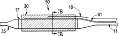
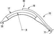
图1为示出了根据本发明的一个实施例的输送设备的透视图。 FIG. 1 is a perspective view showing a delivery device according to one embodiment of the present invention. the
图2为示出了根据本发明的一个实施例的图1所示的输送设备的横截面视图。 FIG. 2 is a cross-sectional view showing the delivery device shown in FIG. 1 according to one embodiment of the present invention. the
图3为示出了根据本发明的一个实施例的图1所示的输送设备的横 截面视图。 Figure 3 is a cross-sectional view showing the delivery device shown in Figure 1 according to one embodiment of the present invention. the
图4A为示出了本发明的另一个方面的横截面视图。 Figure 4A is a cross-sectional view illustrating another aspect of the present invention. the
图4B为示出了本发明的另一个方面的横截面视图。 Figure 4B is a cross-sectional view illustrating another aspect of the present invention. the
图5A为示出了根据本发明的一个实施例的输送系统的远端的侧视图,特别地示出了输送导管,具有沿远端接附的定向构件。 5A is a side view showing the distal end of a delivery system, in particular a delivery catheter, with an orienting member attached along the distal end, according to one embodiment of the present invention. the
图5B为示出了根据本发明的一个实施例的输送系统的远端的横截面视图,特别地示出了输送导管,具有沿远端接附的定向构件。 5B is a cross-sectional view showing the distal end of a delivery system, in particular a delivery catheter, with an orienting member attached along the distal end, according to one embodiment of the present invention. the
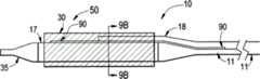
图6A为示出了根据本发明的一个实施例的具有沿定向构件定位的成形的囊(在未膨胀的构造)的输送设备的透视图。 Figure 6A is a perspective view showing a delivery device with a shaped balloon (in an uninflated configuration) positioned along an orienting member, according to one embodiment of the present invention. the
图6B为示出了根据本发明的一个实施例的具有沿定向构件定位的成形的囊(在膨胀的构造)的输送设备的透视图。 6B is a perspective view showing a delivery device with a shaped balloon (in an expanded configuration) positioned along an orienting member, according to one embodiment of the present invention. the
图7A为具有定向构件的导管的示意性的侧视图,定向构件包括能够在激活时为定向构件引入弯曲的形状的主动的元件。 7A is a schematic side view of a catheter with an orienting member comprising an active element capable of introducing a curved shape to the orienting member when activated. the
图7B为具有定向构件的导管的示意性的剖视图,定向构件包括能够在激活时为定向构件引入弯曲的形状的主动的元件。 7B is a schematic cross-sectional view of a catheter with an orienting member comprising an active element capable of introducing a curved shape to the orienting member when activated. the
图7C为具有定向构件的导管的示意性的侧视图,定向构件包括在激活之后为定向构件引入弯曲的形状的主动的元件。 7C is a schematic side view of a catheter with an orienting member including active elements that introduce a curved shape to the orienting member after activation. the
图8A为根据本发明的一个实施例的机械类型的主动的元件的放大的侧视图。 Figure 8A is an enlarged side view of a mechanical type active element according to one embodiment of the present invention. the
图8B为根据本发明的一个实施例的机械类型的主动的元件61的放大的剖视图。 FIG. 8B is an enlarged cross-sectional view of a mechanical type
图8C为根据本发明的一个实施例的机械类型的主动的元件的放大的侧视图。 Figure 8C is an enlarged side view of a mechanical type active element according to one embodiment of the present invention. the
图8D为根据本发明的一个实施例的用作主动的元件61的柔性的顶端导线的放大的侧视剖视图。 8D is an enlarged side cross-sectional view of a flexible tip lead used as
图9A为根据本发明的一个实施例的输送设备的侧视图,示出了加入定向构件的被动的偏置元件。 Figure 9A is a side view of a delivery device showing a passive biasing element incorporated into an orientation member, according to one embodiment of the present invention. the
图9B为根据本发明的一个实施例的输送设备的剖视图,示出了加入定向构件的被动的偏置元件。 9B is a cross-sectional view of a delivery device showing a passive biasing element incorporated into an orientation member, according to one embodiment of the present invention. the
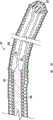
图10A示出了根据本发明的一个实施例的导管输送系统,具有弯曲的形状,在定向构件的外半径上具有第二内腔,还称作较大的弯曲折曲。 Figure 10A illustrates a catheter delivery system according to one embodiment of the present invention having a curved shape with a second lumen on the outer radius of the orienting member, also referred to as a larger curved bend. the
图10B示出了根据本发明的一个实施例的导管输送系统,具有弯曲的形状,在定向构件的内半径上具有第二内腔,有时还称作较小的弯曲折曲。 Figure 10B illustrates a catheter delivery system according to one embodiment of the present invention having a curved shape with a second lumen on the inner radius of the orienting member, sometimes referred to as a smaller curved bend. the
图11A示出了根据本发明的一个实施例的导管输送系统,具有预先折曲的偏置线,具有弯曲的形状,在定向构件的外半径上具有第二内腔,还称作较大的弯曲折曲。 Figure 11A shows a catheter delivery system according to one embodiment of the present invention having a pre-bent bias wire having a curved shape with a second lumen on the outer radius of the orienting member, also referred to as the larger Bend and bend. the
图11B示出了根据本发明的一个实施例的导管输送系统,具有预先折曲的偏置线,具有弯曲的形状,在定向构件的内半径上具有第二内腔,有时还称作较小的弯曲折曲。 11B illustrates a catheter delivery system with a pre-bent bias wire having a curved shape with a second lumen, sometimes referred to as a smaller lumen, on the inner radius of the orienting member, in accordance with one embodiment of the invention. of bends. the
图12A示出了根据本发明的一个实施例的脉管解剖学结构,具有主分支折曲和离开主分支折曲的较大的弯曲(凸出侧)的侧部的分支。 Figure 12A shows a vessel anatomy with a main branch flexure and a lateral branch of the larger curve (convex side) away from the main branch flexure, according to one embodiment of the present invention. the
图12B示出了根据本发明的一个实施例的脉管解剖学结构,具有主分支折曲和离开主分支折曲的较小的弯曲(凹入)的侧部的分支。 Figure 12B shows a vessel anatomy with a main branch flexure and a lesser curved (concave) lateral branch away from the main branch flexure, according to one embodiment of the present invention. the
图13A示出了根据本发明的一个实施例的在具有较大的弯曲解剖学结构的主分支脉管内配置的导线。 Figure 13A illustrates a guidewire deployed within a main branch vessel having a relatively curved anatomy, according to one embodiment of the present invention. the
图13B示出了根据本发明的一个实施例的在具有较小的弯曲解剖学结构的主分支脉管内配置的导线。 Figure 13B illustrates a guidewire deployed within a main branch vessel with less curved anatomy, according to one embodiment of the present invention. the
图14A示出了根据本发明的一个实施例的具有沿两个导线的较大的弯曲解剖学结构的主分支脉管内配置的输送导管。 FIG. 14A shows a main branch intravascularly deployed delivery catheter with a larger curved anatomy along two guidewires, according to one embodiment of the present invention. the
图14A示出了根据本发明的一个实施例的具有沿两个导线的较小的弯曲解剖学结构的主分支脉管内配置的输送导管。 Figure 14A shows a main branch intravascularly deployed delivery catheter with a lesser curved anatomy along two guidewires, according to one embodiment of the present invention. the
具体实施方式Detailed ways
本发明描述了用于设计医用设备输送系统的远侧的部分的新的方法和构造。输送系统能够朝向单一的线上的目标位置跟踪医用设备,并且相对于目标位置预先定向输送系统的有效负载。此设计促进有效负载旋转到用于使用的位置。为了实现此旋转,在将设备前进到目标位置之前,在输送系统的定向构件上引入弯曲的形状。作为此实施例中的示例,弯曲的形状应该选择为使得设备的曲率与目标位置附近的曲率近似匹配。当设备旋转时,设备的弯曲与脉管的弯曲对准,将有效负载定向到希望的位置。 The present invention describes new methods and configurations for designing the distal portion of a medical device delivery system. The delivery system is capable of tracking the medical device towards a target location on a single line, and pre-orients the payload of the delivery system relative to the target location. This design facilitates rotation of the payload into position for use. To achieve this rotation, a curved shape is introduced on the orientation member of the delivery system before advancing the device to the target location. As an example in this embodiment, the curved shape should be chosen such that the curvature of the device approximately matches the curvature in the vicinity of the target location. As the device rotates, the bends of the device align with the bends of the vessel, orienting the payload to the desired location. the
在一个特别的实施例中,本发明描述了用于设计诸如支架输送系统(SDS)的医用设备输送系统的远侧的部分的新的方法和构造。输送系统能够朝向单一的线上的分叉跟踪医用设备,并且朝向侧部的分支小孔预先定向输送系统和设备的侧部的分支特征。此设计促进分叉设备旋转 到用于配置的位置。为了实现此旋转,在将设备前进到分叉之前,在定向构件上引入弯曲的形状。作为此实施例中的示例,弯曲的形状应该选择为使得设备的曲率与小孔的附近的曲率大致匹配,侧部的分支导线出口面向侧部的分支脉管的小孔。当设备旋转时,设备的弯曲匹配主分支脉管的弯曲,并且侧部的分支设备元件将最终面向侧部的分支小孔的方向。这确保一旦全部两个分支走线并且设备被安置在分叉的隆突处,设备对于侧部的分支解剖学结构完全地定向。如果主分支脉管不具有显著的曲率,设备的弯曲的形状还能够用于匹配侧部的分支脉管的弯曲。 In a particular embodiment, the present invention describes new methods and configurations for designing the distal portion of a medical device delivery system, such as a stent delivery system (SDS). The delivery system is capable of tracking the medical device towards the bifurcation on a single line and preorienting the delivery system and the side branching features of the device towards the side branching aperture. This design facilitates the rotation of the bifurcated device into position for deployment. To achieve this rotation, a curved shape is introduced on the orienting member before advancing the device to the bifurcation. As an example in this embodiment, the curved shape should be chosen such that the curvature of the device approximately matches the curvature of the vicinity of the ostium, with the lateral branch wire exit facing the ostium of the lateral branch vessel. As the device is rotated, the curvature of the device matches the curvature of the main branch vessel, and the side branch device elements will eventually face in the direction of the side branch ostium. This ensures that the device is fully oriented to the lateral branch anatomy once both branches are routed and the device is seated at the prominence of the bifurcation. The curved shape of the device can also be used to match the curvature of the side branch vessels if the main branch vessel does not have significant curvature. the
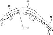
图1和2示出了输送系统,包括适用于处理分叉的类型的导管10,其中,有效负载为囊可扩张的支架。导管10包括可膨胀的囊并且因此可用于配置囊可扩张的支架,然而,应该理解,这里描述的输送系统能够与自扩张的支架一起使用,消除对于膨胀囊和用于传送膨胀流体的内腔的需要,应该注意,如果有效负载为自膨胀的支架,诸如由镍钛诺材料制造的自膨胀的支架,那么设备将需要定位在支架上的外部的抑制护套。导管10通常包括具有近端12、远端13的伸长的导管轴11。至少一个导线内腔14适合接收和经过导线,然而在这里示出了第二导线内腔18。在导管轴11的近端处的膨胀端口20具有用于接收来自外部源的膨胀流体的开口。膨胀端口与存在与轴11内部的打开的环形空间16流体连通。导线入口25位于近侧设备端,并且能够与下面讨论的导线内腔14或18连通。如图1所示,RX导线内腔端口19定位在近端和远端12和13之间。RX导线内腔端口19与导线内腔14或18中的另一个连通。 Figures 1 and 2 show a delivery system comprising a
在图1所示的实施例中,轴11为多内腔轴,典型地挤压或以其它方式形成为具有至少一个导线内腔14,并且可能具有存在于环形空间16内的第二导线内腔18。环形空间在其外部上通过轴11的壁密封,并且因此用作用于传递囊膨胀流体的管道。这里,在设备打算用于在分叉的场所处输送支架的场合,使用能够接收和经过至少两个导线32和33的导管是有利的,然而不是完全必要的。导管轴提供有用于主分支和侧部的分支导线的内腔,这样的内腔分别指定为14和18。 In the embodiment shown in FIG. 1 ,
可膨胀的囊17布置在导管轴11的远侧的区段上,具有固定并且密封到轴11的近端和远端。在其近端处的囊内的开口与环形空间16流体连通,使得当膨胀流体从外部源流动通过膨胀端口20、通过环形空间 16、并且进入囊17时,囊能够接收并且保持膨胀流体。支架30安装在囊17上。看图3。还示出了侧部的分支导线32,指示有效负载跟踪侧部的分支导线,并且从而有效负载配置邻近分叉脉管的侧部的分支小孔进行。此描述绝不打算以任何方式限制本申请的范围,有效负载能够描述为跟踪主分支导线,即,打算在分叉的主分支内配置。 An
定向构件50定位在导管10的远端处。定向构件50安装在轴11的远端处。在特定的设置中,轴11的近端由呈现足够高的扭转柔性的材料构造,使得导管的定向构件部分能够经历定向设备所必须的旋转。使用弹性体的材料在定向构件50的近侧的区域内构造轴是获得此结果的一个方法。在其它设置中,轴11的尺度能够改变以便在定向构件连接到导管的区内给予扭转柔性。例如,轴11的壁厚度能够在靠近轴11结合到定向构件50的位置的区域减小,或替代地,能够减小此区内的轴11的直径。在再一个设置中,定向构件对接焊接到导线内腔14或18中的一个的端部。 Orienting
用于主分支和侧部的分支导线的远侧的出口27和29分别定位在对于侧部的分支导线(没有示出)的远侧的有效负载的大致中间部分和对于主分支导线的导管顶端(35)。
如图4A所示,定向构件50与主分支导线33同轴地设置,即,导线同轴地设置在定向构件50内。定向构件50在囊17内延伸并且在长度的至少一部分与囊17共同定位(图1),支架30在囊和定向构件部分上运载。定向构件50的一部分足够远侧地向有效负载延伸,以便定向设备和有效负载以用于配置。 As shown in FIG. 4A , the
根据本发明的另一个实施例,如图4B所示,定向构件50与主分支导线33同轴地设置,即,导线同轴地设置在定向构件50内。囊17与侧部的分支导线32同轴地定位,支架30在囊上运载。定向构件50的一部分足够远侧地向有效负载延伸,以便定向设备和有效负载以用于配置。 According to another embodiment of the present invention, as shown in FIG. 4B , the
图5A和5B分别示出了根据本发明的一个实施例的输送系统的远端的侧视和剖视图,特别地示出了具有沿远端13接附的定向构件50的导管10。应该注意,为了清晰,已经移除了医用设备(支架),并且这些图中所示的设备还不具有沿远端部分引入的弯曲的形状。 5A and 5B show side and cross-sectional views, respectively, of the distal end of a delivery system, in
如上所述,导管10包括外部主体、具有近端12和远端13的导管 轴11、和形成导线内腔14、18的一个或多个内部主体等。远端还可以具有远侧的顶端35,以当在导线上跟踪和/或导航通过脉管系统时帮助输送系统。 As noted above,
可扩张的构件,囊17沿导管10的远端接附,并且第二导线内腔18沿可扩张的构件17的外部表面定位。 An expandable member, a
接口可以集成在近侧的轴内以允许导管11沿近端12接附到把手、膨胀端口、或相似的设备。在本发明的一个实施例中,导管10制造为在通过脉管系统到目标位置放置的导线上跟踪。可以使用用于在导线上跟踪导管10的本领域中已知的任何方法,包括在线上(OTW)型设备或快速交换设备。因此,导管10分别可以具有OTW(线上)端口或Rx(快速交换)端口。 An interface may be integrated within the proximal shaft to allow attachment of the
如上所述,导管10的目的为将医用设备输送和定向到脉管内的目标位置。作为示例,支架描述为在脉管分叉处以特别的方式定向的医用设备。然而,本领域中的普通技术人员将理解,还能够输送和定向能够加入输送导管的远端的其它医用设备,包括但不限于,医用囊、照相机、传感器、药物输送设备、和各种内腔。 As noted above, the purpose of
本发明的一个关键构思为沿导管10的远端在定向构件50内引入弯曲的形状。弯曲的形状可以在输送过程之前或期间的任何时间制造,但是优选地在将设备前进到目标位置之前进行。因此,输送系统可以包括能够沿定向构件50引入弯曲的形状的元件,以帮助控制导管10和有效负载的定向。元件可以为主动的部件元件或被动的部件元件。 A key concept of the present invention is to introduce a curved shape within the
主动的部件包括能够在引入脉管系统之后成形为弯曲的形状的部件。在优选的实施例中,主动的元件能够进入具有相对直的纵向的构造的脉管系统,诸如图5A所示的设备,并且在随后的时间,优选地一旦设备靠近希望的位置,折曲成希望的形状。然而,此顺序描述不打算限制本发明的范围,并且本领域中的普通技术人员将理解,主动的部件能够在进入脉管系统之前成形为弯曲。 Active components include components that can be formed into a curved shape after introduction into the vasculature. In preferred embodiments, the active element is capable of entering vasculature with a relatively straight longitudinal configuration, such as the device shown in FIG. the shape of hope. However, this sequential description is not intended to limit the scope of the invention, and one of ordinary skill in the art will understand that the active component can be shaped into a bend prior to entering the vasculature. the
有数种方法能够用于主动地沿导管10的远端引入弯曲的形状且在此示例性地呈现。本领域中的普通技术人员将理解还可以使用其它方法。 There are several methods that can be used to actively introduce a curved shape along the distal end of
能够用于引入弯曲的形状的一个方法利用液压和当充满时呈现弯曲的形状的压力腔室。例如,弯曲的或成形的医用囊可以加入定向构件 50或沿导管10。图6A和6B为具有与囊17分开的沿定向构件50定位的成形的囊60的导管10的透视图。 One method that can be used to introduce a curved shape utilizes hydraulic pressure and pressure chambers that assume a curved shape when filled. For example, a curved or shaped medical balloon can be added to the
囊60在图6A中示出为处于未膨胀的构造,导管10和定向构件50采取相对直的位置。在输送期间,囊60在未膨胀的、受约束的和缠绕的构造中保持相对直和柔性。为了沿定向构件50给予弯曲的形状,通过输送导管10将流体引入囊60,增加囊的内部压力并且最终充满囊60,直到囊60呈现弯曲的形状,如图6B所示。膨胀的囊具有足够强度和刚性以将定向构件50偏转到希望的弯曲的形状。流体可以是可压缩的或不可压缩的,但是优选地为诸如盐水的大致不可压缩的生物相容的流体。 Balloon 60 is shown in FIG. 6A in an uninflated configuration, with
在本发明的另一个实施例中,定向构件50包括能够在引入一些类型的能量时改变形状的至少一个元件。此能量源可以采取机械的、电的、化学的、热的或磁的能量的形式。 In another embodiment of the invention, the orienting
图7A和7B为具有定向构件50的导管10的侧视和剖视图,定向构件50包括能够在激活时将弯曲的形状引入定向构件50的主动的元件61。图7C为示出了在激活主动的元件61之后处于弯曲的构造的定向构件50的侧视图。 7A and 7B are side and cross-sectional views of a
主动的元件61典型地通过临床医生或技术人员操纵或触发与主动的元件相关的可操作的部件激活。在许多情况中,可操作的部件沿导管10的近端定位。从而,利用主动的元件61的输送导管10的一些实施例具有在可操作的部件和主动的元件61之间的通信装置。在本发明的其它实施例中,主动的元件61自身或主动的元件的部件零件可以横贯通过导管10内的第二内腔到达近端部分12。在本发明的再其它的实施例中,主动的元件61能够通过环境状态的改变自动激活。在此后面的情况中,主动的部件具有沿导管10的近端部分12的手动地可操作的部件可以不是必要的。
在本发明的一个实施例中,主动的元件61为通过施加通过接附到近侧地定位的可操作的部件的拉线或相似地构造的连通构件传递的相对运动或力改变定向构件50的形状的一个或多个机械的元件。这些元件61可以包括线、可偏转的管、可偏转的导管、或可偏转的顶端导线(例如Cordis Steer-it TM导线)并且通常在可偏转的顶端导管和导线的技术领域中已知。 In one embodiment of the invention, the
图8A和8B为根据本发明的一个实施例的另一个机械类型的主动的元件61的放大的侧视和剖视图。机械的主动的元件61包括沿导管轴11的远端部分接附的半顺性的元件81。柔性的元件82固定地接附到半顺性的元件81的远端,并且具有足够的柔性以当处于压缩的负载状态下时折曲,以在定向构件50内提供希望的曲率。拉线80接附到沿柔性的构件82的远端定位的锚83,并且近侧地行进通过拉线内腔84和导管轴11到达沿导管10的近端定位的可操作的部件。拉线内腔84偏离中心,导致柔性的构件82在特别的方向偏转。即,偏移拉线内腔导致柔性的构件82弯曲,使得内半径或较小的弯曲在拉线内腔84的侧上。 8A and 8B are enlarged side and cross-sectional views of another mechanical type
主动的元件61在定向构件50内或沿定向构件50定位,并且当被引入脉管系统和前进到希望的位置时保持相对直和柔性。
当临床医生希望引入弯曲的形状时,他在输送导管10的近端处将机械的力或运动给予拉线80,拉线80将此能量转换为沿可偏转的远端部分到与定向构件50相关的可偏转的元件82的运动。此偏转折曲定向构件50以呈现弯曲的形状。图8C为根据本发明的一个实施例的当偏转为弯曲的形状时的机械的主动的元件61的放大的侧视图。 When the clinician wishes to introduce a curved shape, he imparts mechanical force or movement at the proximal end of the
在本发明的另一个实施例中,可偏转的顶端导线还可以适用于作为与定向构件50一起的主动的元件61。相似的导线构思在全文作为参考加入这里的题目为“Guidewire With Deflectable Tip”的美国专利No.7,128,718中披露。披露的可偏转的导线为双方向的并且具有包括纵向的海波管和接附到海波管的远端的弹簧线圈的可偏转的远侧的顶端。可偏转的导线还包括接附到弹簧线圈的远端的纵向地可运动的偏转构件和从海波管的远端延伸到弹簧线圈的远端的用于提供远侧的顶端的非常精确的偏转的顶端保持构件。 In another embodiment of the invention, a deflectable tip lead may also be adapted as an
图8D为根据本发明的一个实施例的用作主动的元件61的柔性的顶端导线的放大的侧视剖视图。主动地可折曲的导线包括伸长的海波管86、接附到并且从海波管86的远端延伸的螺旋线圈88。螺旋线圈88优选地由铂钨形成,近侧的匝缠绕为使得近侧的部分的邻近的匝与彼此接触。 8D is an enlarged side cross-sectional view of a flexible tip lead used as
虽然本发明的优选的实施例包括螺旋线圈88,此元件可以采取任何柔性的圆柱的构件的形式,诸如例如薄金属管,具有或不具有例如通过激光切割移除的管的部分,以便形成非常柔性的圆柱的构件。伸长的、 偏转构件85从控制把手的近端延伸通过海波管86并且通过螺旋线圈88,并且连接到布置在螺旋线圈88的远侧的顶端处的接附构件或圆形的珠87内。另外,保持带89连接到海波管86的远端并且还连接到圆形的珠87。 Although the preferred embodiment of the invention includes a
操作中,因为预先成形的偏转带134和保持带89的弯曲,主动的元件61的远侧的顶端正常地被偏置到如图8D所示的向下弯曲的位置。当沿导管10的近端的可操作的部件远侧地运动时,偏转构件85将远侧地运动,由此导致偏转带134在远侧的方向运动。当偏转带远侧地运动时,力施加到圆形的珠87的顶部部分。保持带89接附到珠87的下部部分以由此将珠保持在距离海波管86的远端的固定的距离。当偏转带134运动到右面时,导致导线的顶端向下偏转到偏转的最大位置。 In operation, the distal tip of
在本发明的另一个实施例中,定向构件50包括对应电势或电流的改变来改变形状的至少一个主动的元件61。在这些状态下改变形状的电主动的元件61在本技术领域中已知,并且包括压电的、具有电阻加热元件的双金属片和MEMS(机电促动器)设备。电主动的元件61还可以包括在电势的影响下呈现形状记忆性质的材料。本技术领域中已知的一个这样的材料为当电势增加时收缩并且当去极化时放松或伸长的一族导电聚合物。这些元件的收缩/放松可以用于局部地导致机械元件位移,导致将折曲或弯曲引入定向构件50。 In another embodiment of the invention, the orienting
当临床医生希望引入弯曲的形状时,他允许电能流到电主动的元件61。这可以例如通过闭合在导管10的近端12处的开关实现。此电势或电流改变导致电主动的元件61改变形状或偏转。此偏转折曲定向构件50。 When the clinician wishes to introduce a curved shape, he allows electrical energy to flow to the
在本发明的再一个实施例中,定向构件50具有对应磁场的改变来改变形状的至少一个主动的元件61。磁场可以在身体或脉管系统的内部或外部。用于此类型的应用的一个特别的类型的材料为磁致伸缩的材料。磁致伸缩为响应改变其磁化的材料的物理尺度的改变。换句话说,当磁致伸缩材料经历磁场时,磁致伸缩材料将磁的能量转换为动能并且改变形状。磁致伸缩材料的一个商标为TerfenolTM。 In yet another embodiment of the invention, the
当临床医生希望引入弯曲的形状时,他使磁致伸缩主动的元件61经历磁场。此磁场导致磁致伸缩元件61将磁的能量转换为动能并且改变形状。此偏转折曲定向构件50以呈现弯曲的形状。 When the clinician wishes to introduce a curved shape, he subjects the magnetostrictive
在其它实施例中,导管10,特别地定向构件50具有含铁的或铁磁的部分或元件61并且响应外部磁场。从而,定向构件50可以朝向吸引的磁场折曲,或者远离排斥的磁场折曲,导致导管10内的相似的折曲。 In other embodiments, the
定向构件50还可以通过经由化学地响应的元件61施加的力主动地折曲,元件61响应局部的化学性质的改变来改变形状。此改变可以通过化学主动的元件61内的化学反应或化学浓度的改变导致。在任一情况中,化学响应的元件61可以响应局部的化学性质的改变增大或延长并且改变形状。本领域中的普通技术人员将理解,此形状改变或增大可以直接在定向构件50内给予弯曲。相似地,形状改变或增大可以间接地通过局部地操纵机械主动的元件在定向构件50内给予弯曲。 Orienting
相似地,通过热响应的主动的元件61施加的力也可以主动地操纵定向构件50。在这些实施例中,局部温度的改变可以作为将设备放置到温暖的脉管内的结果,或替代地,通过引入热的或冷的媒体改变局部温度。在一个特别的实施例中,热主动的元件61与沿通过通道的导管10的近端部分定位的可操作的部件流体连通。临床医生可以初始媒体流动通过导管通道到达热主动的元件61,导致热主动的元件改变形状并且弯曲或折曲定向构件50。 Similarly, force applied by the thermally responsive
在一个实施例中,热响应的主动的元件61可以对应温度的改变来改变形状。例如,材料可以作为局部温度增加或降低的结果经历形状的改变。 In one embodiment, thermally responsive
在另一个实施例中,热响应的主动的元件61包括具有不同的热膨胀系数的部件-例如双金属片。当将元件引入不同的热环境时,不同的部件不同地响应,并且以不同的速率扩张。这将导致热响应的主动的元件61改变形状或折曲。此偏转折曲定向构件50以呈现弯曲的形状。另外,具有各向异性的热扩张性质的材料可以用于沿定向构件50给予曲率。本领域中的普通技术人员将理解,通过热扩张的此形状改变可以直接在定向构件50内给予弯曲。相似地,通过热扩张的形状改变可以间接地通过局部地操纵机械主动的元件在定向构件50内给予弯曲。 In another embodiment, the thermally responsive
热响应的主动的元件61还可以经历相位改变,导致材料呈现形状记忆或超弹性的特性。一种这样的材料为镍钛诺。 The thermally responsive
镍钛诺用于多种应用,包括如上文中所述的医用设备应用。由于多种原因,包括其生物力学相容性、其生物相容性、其抗疲劳性、其抗纽 结性、其均一的塑性变形、其磁共振成像相容性、其施加恒定的和平缓的向外压力的能力、其动态干扰、其热配置能力、其弹性配置能力、其滞后现象特性,并且适度地不透射线,镍钛诺或镍钛合金广泛地用于制造或构造医用设备。 Nitinol is used in a variety of applications, including medical device applications as described above. For a number of reasons, including its biomechanical compatibility, its biocompatibility, its fatigue resistance, its kink resistance, its uniform plastic deformation, its magnetic resonance imaging compatibility, its constant and gentle application Its outward pressure capability, its dynamic disturbance, its thermal deployment capability, its elastic deployment capability, its hysteresis properties, and being moderately radiopaque, Nitinol or Nitinol alloys are widely used in the manufacture or construction of medical devices. the
如上文中所述的,镍钛诺呈现形状记忆和/或超弹性的特性。形状记忆特性可以简单地如下文中所述。金属结构,例如,处于奥氏体相位的镍钛诺管可以被冷却到使得其处于马氏体相位的温度。一旦处于马氏体相位,可以通过施加应力将镍钛诺管变形为特别的构造或形状。只要镍钛诺管保持在马氏体相位,镍钛诺管将保持在其变形的形状。如果镍钛诺管被加热到足够导致镍钛诺管达到奥氏体相位的温度,镍钛诺管将返回其原始的或规划的形状。原始的形状通过众所周知的技术规划为特别的形状。 As noted above, Nitinol exhibits shape memory and/or superelastic properties. The shape memory properties may simply be as described below. A metallic structure, eg, a nitinol tube in the austenite phase may be cooled to a temperature such that it is in the martensitic phase. Once in the martensitic phase, the nitinol tube can be deformed into a particular configuration or shape by applying stress. As long as the nitinol tube remains in the martensitic phase, the nitinol tube will remain in its deformed shape. If the nitinol tube is heated to a temperature sufficient to cause the nitinol tube to reach the austenitic phase, the nitinol tube will return to its original or planned shape. The original shape is programmed into a particular shape by well-known techniques. the
超弹性的特性可以简单地如下文中所述。金属结构,例如,处于奥氏体相位的镍钛诺管可以通过施加机械的能量变形为特别的形状或构造。施加机械的能量导致应力引入的马氏体相位转换。换句话说,机械的能量导致镍钛诺管从奥氏体相位转换到马氏体相位。通过利用适当的测量器具,能够确定来自机械的能量的应力导致镍钛诺管内的温度下降。一旦机械的能量或应力释放,镍钛诺管经历回到奥氏体相位的另一个机械的相位转换并且从而回到其初始的或规划的形状。如上文中所述,原始的形状通过众所周知的技术规划。马氏体和奥氏体相位为许多金属中的通用的相位。 The properties of superelasticity can be simply as described below. Metallic structures, such as nitinol tubes in the austenitic phase, can be deformed into particular shapes or configurations by the application of mechanical energy. Application of mechanical energy results in a stress-induced martensitic phase transformation. In other words, mechanical energy causes the nitinol tube to transform from the austenite phase to the martensitic phase. By using appropriate measuring instruments, it can be determined that the stress from the mechanical energy causes the temperature drop inside the Nitinol tube. Once the mechanical energy or stress is released, the nitinol tube undergoes another mechanical phase transition back to the austenitic phase and thereby returns to its original or planned shape. As mentioned above, the original shape was planned by well known techniques. The martensite and austenite phases are common phases in many metals. the
由镍钛诺构造的医用设备典型地用于马氏体相位和/或奥氏体相位。马氏体相位为低温相位。处于马氏体相位的材料典型地非常软和有延展性。这些性质使得更加容易将镍钛诺成形或构造为复杂的或综合的结构。奥氏体相位为高温相位。处于奥氏体相位的材料通常具有比处于马氏体相位的材料高得多的强度。典型地,许多医用设备被冷却到马氏体相位以用于操纵和装载到输送系统内。当设备在体温配置时,它们返回奥氏体相位。 Medical devices constructed from Nitinol are typically used in the martensitic and/or austenitic phases. The martensitic phase is a low-temperature phase. Materials in the martensitic phase are typically very soft and ductile. These properties make it easier to shape or structure nitinol into complex or composite structures. The austenite phase is a high temperature phase. Materials in the austenite phase generally have much higher strength than materials in the martensitic phase. Typically, many medical devices are cooled to the martensitic phase for handling and loading into delivery systems. When the devices are configured at body temperature, they return to the austenitic phase. the
也可以使用具有形状记忆特性的其它材料,例如,一些聚合物和金属复合物材料。 Other materials with shape memory properties may also be used, for example, some polymer and metal composite materials. the
弯曲的形状还可以形成在导管10的远端内,即,使用被动的部件的定向构件50。被动的部件为不能在被引入脉管系统之后成形的元件, 但是能够在将设备引入脉管系统之前成形为弯曲的形状。然而,即使一旦引入脉管系统或身体内腔,被动的部件大致保持给予其的弯曲的形状。这可以在制造过程期间进行,或者替代地,通过临床医生或技术人员正好在将输送设备引入脉管系统之前进行。 The curved shape can also be formed in the distal end of the
许多加入导管10的远端的部件可以设计为被动的部件以促进引入弯曲的形状。例如,在支架输送系统的情况中,支架自身可以在插入脉管之前制造或成形为具有弯曲的形状。另外,导管内部主体、导线内腔14,包括主分支元件、侧部的分支元件、或全部元件,可以在引入脉管之前制造或随后成形为具有弯曲的形状。 Many of the components added to the distal end of
除了构成上面描述的输送系统的典型的部件,可以添加其它部件以引入或促进定向构件50内或沿导管10的远端的弯曲的形状。在本发明的一个实施例中,偏置元件添加到定向构件50以促进弯曲的形状。此元件可以例如以增加刚性的线、带或挤压物的形式。本领域中的普通技术人员还将理解,能够使用其它偏置元件。 In addition to the typical components that make up the delivery system described above, other components may be added to introduce or facilitate the curved shape within orienting
图9A和9B示出了根据本发明的一个实施例的输送系统,导管10的侧视和剖视图,具有沿远端13加入定向构件50的偏置元件90。 9A and 9B illustrate a delivery system, side and cross-sectional views of a
如图所示,被动的输送设备具有与图1到4B所示的输送设备10相似的部件,包括用于在导线33上跟踪的内部主体导线内腔14、外部主体导管轴11、扩张设备(囊)17、远侧的顶端35、和用于第二或侧部的分支导线32的第二内腔18。这些图中还示出了医用设备,支架30。然而,图9A和9B所示的输送设备10还具有在囊17近侧的密封处开始并且沿定向构件50远侧地行进到靠近远端35的点的一对偏置线90。偏置线90能够折曲并且成组以沿定向构件50形成弯曲的形状。 As shown, the passive delivery device has similar components to the
应该注意,图9A示出了在远端上引入弯曲的形状之前的处于相对直的构造的偏置线90和导管10输送系统。如上文中披露的,偏置线90可以例如在制造期间或正好在插入脉管之前通过临床医生折曲。 It should be noted that Figure 9A shows the
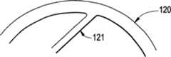
图10A和10B示出了包括具有沿远端的半径R的弯曲的形状的导管输送设备10。图10A示出了包括还称作较大的弯曲折曲的具有在定向构件50的外半径上的第二内腔18的弯曲的形状的输送设备。图10B示出了包括有时还称作较小的弯曲折曲的具有在定向构件50的内半径上的第二内腔18的弯曲的形状的输送设备。 10A and 10B illustrate a
存在并且在这里示例性地示出了数种能够用于沿导管输送系统10 的远端在定向构件50内被动地引入弯曲的形状的方法。本领域中的普通技术人员将理解也可以使用其它方法。 Several methods exist and are exemplarily shown here that can be used to passively introduce a curved shape within the
如上面讨论的,弯曲的形状可以在制造过程期间,或替代地,通过临床医生或技术人员正好在将输送导管10引入脉管系统或身体内腔之前设定到导管输送设备10内。 As discussed above, the curved shape may be set into
在本发明的一个实施例中,输送导管10和部件,特别地定向构件50,能够制造为弯曲的形状。可以制造数种不同的弯曲的形状以允许临床医生具有能够从其选择具有最接近地类似实际的脉管解剖学结构的弯曲的形状的输送导管10的组。替代地,定向构件50可以根据需要适当地成形。 In one embodiment of the invention, the
在本发明的另一个实施例中,包括输送导管10的远端的典型的部件是柔性的。具有预先确定的弯曲的形状的辅助的被动的部件,诸如预先折曲的偏置线91,加入远端并且为定向构件50提供弯曲的形状。替代地,预先折曲的偏置线91可以前进或缩回通过身体内部的内腔14以为导管10的柔性的远端部分提供设定形状。 In another embodiment of the invention, the exemplary components comprising the distal end of
包括沿定向构件50引入具有半径R的弯曲的形状的预先折曲的偏置线的导管输送设备10在图11A和11B中示出。图11A示出了包括具有在定向构件50的外半径(较大的弯曲折曲)上的第二内腔18的弯曲的形状的输送导管10。图11B示出了包括具有在定向构件50的内半径(较小的弯曲折曲)上的第二内腔18的弯曲的形状的输送设备。在每个情况中,预先折曲的偏置线91加入定向构件50,以为导管10的远端部分提供希望的弯曲的形状。 A
在本发明的再一个实施例中,包括输送导管10的远端13的部件中的一个或多个由能够通过临床医生在将导管10引入脉管之前塑性地变形的材料制造。此输送之前的机械的折曲可以通过经由临床医生使用或不使用折曲工具进行的实际的操纵和成形。折曲的其它方法能够包括特殊地设计的包装,当以一定的方式移除时,将在输送设备的远端上引入折曲。例如,包装可以设计为,如果在一个特别的方向从包装移除输送导管10,给予用于在较大的弯曲脉管解剖学结构中使用的凸出(外半径)的折曲,并且,如果在不同的方向移除输送导管10,给予用于在较小的弯曲脉管解剖学结构中使用的凹入(内半径)的折曲。 In yet another embodiment of the invention, one or more of the components including the
另外,对于在引入脉管系统之后的主动的折曲描述的方法可以用于 在将输送导管10或定向构件50引入解剖学结构之前在输送导管10或定向构件50内引入被动的弯曲的形状。 Additionally, the methods described for active bending after introduction into the vasculature may be used to introduce a passively curved shape within the
弯曲的形状应该选择为使得靠近目标有效负载区的设备的曲率,即,定向构件50的曲率,大致匹配脉管系统解剖学结构的曲率。一种确定脉管的解剖学结构的方法为将初级的输送导线33插入脉管并且观察相对于脉管的曲率的通过导线33采取的曲率,或者,在分叉脉管的情况中,侧部的分支脉管的小孔。 The curved shape should be chosen such that the curvature of the device, ie, the curvature of the orienting
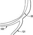
作为示例,图12A示出了具有主分支折曲120和离开主分支折曲的较大的弯曲(凸出侧)的侧部的分支121的脉管解剖学结构。图13A示出了在具有较大的弯曲解剖学结构的相似的主分支脉管120内配置的导线33并且帮助观察脉管解剖学结构。为了用随后输送的第二导线32进入侧部的分支121,临床医生将使用如图10A所示的具有较大的弯曲侧部的分支折曲的输送导管10。在初级的导线33上跟踪输送导管10到分叉位置,并且自然地旋转到适当的位置,使得第二导线管18面向侧部的分支脉管121。如图14A所示,第二导线32能够随后前进通过第二导线管18进入侧部的分支脉管121。这确保一旦全部分支走线并且设备安置在分叉的隆突处,设备对于侧部的分支解剖学结构完全地定向。 As an example, FIG. 12A shows a vascular anatomy with a
相似地,图12B示出了具有主分支折曲和离开主分支折曲的较小的弯曲(凹入侧)的侧部的分支的脉管解剖学结构。导线能够插入脉管的主分支以帮助观察脉管解剖学结构。图13B示出了在具有较小的弯曲解剖学结构的相似的主分支脉管内配置的导线33。为了用随后输送的第二导线32进入侧部的分支,临床医生将使用如图10B所示的具有较小的弯曲侧部的分支折曲的输送导管10。在初级的导线33上跟踪输送导管10到分叉位置,并且自然地旋转到适当的位置,使得第二导线管18面向侧部的分支脉管121。如图14B所示,第二导线32能够随后前进通过第二导线管18进入侧部的分支脉管121。这确保一旦全部分支走线并且设备安置在分叉的隆突处,设备对于侧部的分支解剖学结构完全地定向。 Similarly, Figure 12B shows the vascular anatomy of a branch with a main branch flexure and a side of a smaller bend (concave side) away from the main branch flexure. Guidewires can be inserted into the main branches of vessels to aid in visualization of vascular anatomy. Figure 13B shows
当选择或沿输送导管系统10的远端引入弯曲的形状时,可以考虑数个因素,特别地,弯曲的形状的位置和形状,和侧部的分支元件对于弯曲的形状的朝向。 When selecting or introducing a curved shape along the distal end of the
此外,容易理解,由于设备的多功能性,能够类似地实现在侧部的 分支121内的执行。例如,如图4B所示,通过使得主分支导线33通过定向构件50(具有对于外部负载相同地定位的外部),囊17和侧部的分支导线32在有效负载(支架)30内,能够通过当定向构件通过脉管内的折曲时允许定向构件50旋转导管设备10的远端适当地定向设备。通过此设置,支架能够通入侧部的分支121的小孔并且随后在侧部的分支121内配置。 Furthermore, it is readily understood that due to the versatility of the device, execution within the
应该理解,本披露物在许多方面仅是示例性的。细节可以在不超出本发明的范围的情况下改变,特别地在与零件的形状、尺寸、材料和设置有关的方面。因此,本发明的范围在后附的权利要求书中限定。 It should be understood that this disclosure is exemplary in many respects. Details may be changed without departing from the scope of the invention, particularly in respects to the shape, size, material and arrangement of parts. Accordingly, the scope of the invention is defined in the appended claims. the
Claims (81)
Translated fromChineseApplications Claiming Priority (3)
| Application Number | Priority Date | Filing Date | Title |
|---|---|---|---|
| US75712306P | 2006-01-06 | 2006-01-06 | |
| US60/757,123 | 2006-01-06 | ||
| PCT/US2007/060243WO2007082189A2 (en) | 2006-01-06 | 2007-01-08 | A medical delivery system of a medically useful payload |
Publications (2)
| Publication Number | Publication Date |
|---|---|
| CN101448540A CN101448540A (en) | 2009-06-03 |
| CN101448540Btrue CN101448540B (en) | 2012-08-01 |
Family
ID=38181070
Family Applications (1)
| Application Number | Title | Priority Date | Filing Date |
|---|---|---|---|
| CN2007800068604AExpired - Fee RelatedCN101448540B (en) | 2006-01-06 | 2007-01-08 | Medical Delivery Systems for Transporting Medical Payloads |
Country Status (9)
| Country | Link |
|---|---|
| US (2) | US20070270781A1 (en) |
| EP (1) | EP1979036B1 (en) |
| JP (1) | JP5179377B2 (en) |
| CN (1) | CN101448540B (en) |
| AU (1) | AU2007204738B2 (en) |
| CA (1) | CA2636286C (en) |
| ES (1) | ES2436409T3 (en) |
| MX (1) | MX2008008848A (en) |
| WO (1) | WO2007082189A2 (en) |
Families Citing this family (36)
| Publication number | Priority date | Publication date | Assignee | Title |
|---|---|---|---|---|
| US7776310B2 (en) | 2000-11-16 | 2010-08-17 | Microspherix Llc | Flexible and/or elastic brachytherapy seed or strand |
| US7736293B2 (en) | 2005-07-22 | 2010-06-15 | Biocompatibles Uk Limited | Implants for use in brachytherapy and other radiation therapy that resist migration and rotation |
| US8187159B2 (en)* | 2005-07-22 | 2012-05-29 | Biocompatibles, UK | Therapeutic member including a rail used in brachytherapy and other radiation therapy |
| US8518052B2 (en)* | 2006-01-06 | 2013-08-27 | Cordis Corporation | Medical delivery system for delivery of a medically useful payload |
| JP4868905B2 (en)* | 2006-03-24 | 2012-02-01 | オリンパス株式会社 | Receiver |
| US9387100B2 (en) | 2007-01-08 | 2016-07-12 | Cardinal Health Switzerland GmbH | Intraluminal medical device having variable axial flexibility about the circumference of the device |
| JP4357536B2 (en) | 2007-02-16 | 2009-11-04 | 株式会社神戸製鋼所 | Copper alloy sheet for electrical and electronic parts with excellent strength and formability |
| EP2216067B1 (en)* | 2007-10-27 | 2016-07-13 | Kaneka Corporation | Catheter |
| US8545440B2 (en) | 2007-12-21 | 2013-10-01 | Carticept Medical, Inc. | Injection system for delivering multiple fluids within the anatomy |
| WO2009086182A1 (en) | 2007-12-21 | 2009-07-09 | Carticept Medical, Inc. | Articular injection system |
| US9044542B2 (en) | 2007-12-21 | 2015-06-02 | Carticept Medical, Inc. | Imaging-guided anesthesia injection systems and methods |
| US10456554B2 (en)* | 2008-04-17 | 2019-10-29 | W. L. Gore & Associates, Inc. | Device delivery catheter having a curved distal tip |
| JP5526311B2 (en) | 2008-08-26 | 2014-06-18 | クック メディカル テクノロジーズ エルエルシー | Thorax guide |
| CN102413863A (en)* | 2009-10-14 | 2012-04-11 | 奥林巴斯医疗株式会社 | Flexible medical tube and insertion part of medical instrument |
| CN101961269B (en)* | 2010-04-19 | 2012-09-05 | 杭州启明医疗器械有限公司 | Conveying device for conveying artificial cardiac valve replacement device |
| CN103327935B (en)* | 2010-12-14 | 2016-10-19 | 杭州启明医疗器械有限公司 | Including the alignment device of device, set group and method |
| CN102525380B (en)* | 2010-12-23 | 2016-03-30 | 德昌电机(深圳)有限公司 | Warp architecture and use the endoscope and image processing device of this warp architecture, stomach tube and mechanical joint |
| WO2013170053A1 (en) | 2012-05-09 | 2013-11-14 | The Regents Of The University Of Michigan | Linear magnetic drive transducer for ultrasound imaging |
| EP2887994B1 (en) | 2012-08-24 | 2019-02-20 | Boston Scientific Corporation | Device for improving brachytherapy |
| US10206592B2 (en)* | 2012-09-14 | 2019-02-19 | Endotronix, Inc. | Pressure sensor, anchor, delivery system and method |
| WO2014100382A1 (en)* | 2012-12-20 | 2014-06-26 | Jeremy Stigall | Implant delivery system and implants |
| US10039657B2 (en) | 2012-12-21 | 2018-08-07 | CARDINAL HEALTH SWITZERLAND 515 GmbH | Cannulation guiding device for bifurcated stent and method of use |
| US20140180385A1 (en)* | 2012-12-21 | 2014-06-26 | Cordis Corporation | Stent cannulation guiding device and method of use |
| US9398921B2 (en)* | 2013-01-30 | 2016-07-26 | Invatec S.P.A. | Catheter with deflectable tip |
| EP2805695A1 (en)* | 2013-05-21 | 2014-11-26 | Medtentia International Ltd Oy | Medical system for annuloplasty |
| CN103293593A (en)* | 2013-05-27 | 2013-09-11 | 上海大学 | Buckling and deforming optical fiber and application thereof in endoscopic catheter |
| WO2015045429A1 (en)* | 2013-09-24 | 2015-04-02 | 公立大学法人広島市立大学 | Elastic tube, control device, and medical equipment |
| WO2015052852A1 (en)* | 2013-10-10 | 2015-04-16 | アイハート・メディカル株式会社 | Blood-vessel catheter system, and cto-lesion penetration method |
| KR102211335B1 (en)* | 2013-12-20 | 2021-02-03 | 마이크로벤션, 인코포레이티드 | Device delivery system |
| WO2017070147A1 (en) | 2015-10-23 | 2017-04-27 | Boston Scientific Scimed, Inc. | Radioactive stents |
| US20220265969A1 (en)* | 2019-07-15 | 2022-08-25 | Ecole Polytechnique Federale De Lausanne (Epfl) | Ultraflexible Flow Directed Device And System |
| US11103324B2 (en)* | 2019-08-28 | 2021-08-31 | Massachusetts Institute Of Technology | Magnetically steerable continuum robotic guidewires for neurovascular applications |
| US20210402156A1 (en)* | 2020-06-30 | 2021-12-30 | Becton, Dickinson And Company | Catheter tip passive control device and related systems and methods |
| WO2023087477A1 (en)* | 2021-11-17 | 2023-05-25 | 上海腾复医疗科技有限公司 | Bending-adjustable sheath |
| CN113908404A (en)* | 2021-11-17 | 2022-01-11 | 上海腾复医疗科技有限公司 | Adjustable bent sheath pipe |
| WO2023114368A2 (en)* | 2021-12-17 | 2023-06-22 | Deinde Medical Corp. | Steerable catheters and related methods |
Citations (5)
| Publication number | Priority date | Publication date | Assignee | Title |
|---|---|---|---|---|
| EP0508473A2 (en)* | 1991-04-11 | 1992-10-14 | Endovascular Technologies, Inc. | Endovascular graft having bifurcation and apparatus and method for deploying the same |
| US5843153A (en)* | 1997-07-15 | 1998-12-01 | Sulzer Intermedics Inc. | Steerable endocardial lead using magnetostrictive material and a magnetic field |
| US6869414B2 (en)* | 2002-03-22 | 2005-03-22 | Cardiac Pacemakers, Inc. | Pre-shaped catheter with proximal articulation and pre-formed distal end |
| US6939338B2 (en)* | 2002-04-19 | 2005-09-06 | Medtronic, Inc. | Methods and apparatus for imparting curves in elongated medical catheters |
| US6979319B2 (en)* | 2001-12-31 | 2005-12-27 | Cardiac Pacemakers, Inc. | Telescoping guide catheter with peel-away outer sheath |
Family Cites Families (31)
| Publication number | Priority date | Publication date | Assignee | Title |
|---|---|---|---|---|
| US6221102B1 (en)* | 1983-12-09 | 2001-04-24 | Endovascular Technologies, Inc. | Intraluminal grafting system |
| US5041126A (en)* | 1987-03-13 | 1991-08-20 | Cook Incorporated | Endovascular stent and delivery system |
| JPH021292A (en)* | 1988-06-01 | 1990-01-05 | Terumo Corp | Catheter tube |
| US4911148A (en)* | 1989-03-14 | 1990-03-27 | Intramed Laboratories, Inc. | Deflectable-end endoscope with detachable flexible shaft assembly |
| US5242721A (en)* | 1989-11-27 | 1993-09-07 | Sumitomo Rubber Industries, Ltd. | Structural member of pipe shape |
| US5329923A (en)* | 1991-02-15 | 1994-07-19 | Lundquist Ingemar H | Torquable catheter |
| US5454787A (en)* | 1991-02-15 | 1995-10-03 | Lundquist; Ingemar H. | Torquable tubular assembly and torquable catheter utilizing the same |
| JPH05177002A (en)* | 1991-09-17 | 1993-07-20 | Olympus Optical Co Ltd | Mechanochemical actuator and medical tube |
| US5397321A (en)* | 1993-07-30 | 1995-03-14 | Ep Technologies, Inc. | Variable curve electrophysiology catheter |
| US6132390A (en)* | 1996-02-28 | 2000-10-17 | Eupalamus Llc | Handle for manipulation of a stylet used for deflecting a tip of a lead or catheter |
| AU2785597A (en)* | 1996-05-31 | 1998-01-05 | Bard Galway Limited | Bifurcated endovascular stents and method and apparatus for their placement |
| JP3698831B2 (en)* | 1996-09-20 | 2005-09-21 | 新弥 勝山 | Intestinal obstruction treatment catheter |
| WO1998038947A1 (en)* | 1997-03-05 | 1998-09-11 | Scimed Life Systems, Inc. | Conformal laminate stent device |
| KR20010052459A (en)* | 1998-05-29 | 2001-06-25 | 바이-패스, 인크. | Methods and devices for vascular surgery |
| US6187034B1 (en)* | 1999-01-13 | 2001-02-13 | John J. Frantzen | Segmented stent for flexible stent delivery system |
| US7744613B2 (en)* | 1999-06-25 | 2010-06-29 | Usgi Medical, Inc. | Apparatus and methods for forming and securing gastrointestinal tissue folds |
| US6246914B1 (en)* | 1999-08-12 | 2001-06-12 | Irvine Biomedical, Inc. | High torque catheter and methods thereof |
| US6829497B2 (en)* | 1999-09-21 | 2004-12-07 | Jamil Mogul | Steerable diagnostic catheters |
| US6375660B1 (en)* | 1999-11-22 | 2002-04-23 | Cordis Corporation | Stent delivery system with a fixed guide wire |
| US6554848B2 (en)* | 2000-06-02 | 2003-04-29 | Advanced Cardiovascular Systems, Inc. | Marker device for rotationally orienting a stent delivery system prior to deploying a curved self-expanding stent |
| US6544218B1 (en) | 2000-07-26 | 2003-04-08 | Advanced Cardiovascular Systems, Inc. | Catheter with biased shaft |
| US7018372B2 (en)* | 2001-04-17 | 2006-03-28 | Salviac Limited | Catheter |
| US6605110B2 (en)* | 2001-06-29 | 2003-08-12 | Advanced Cardiovascular Systems, Inc. | Stent with enhanced bendability and flexibility |
| US7493156B2 (en)* | 2002-01-07 | 2009-02-17 | Cardiac Pacemakers, Inc. | Steerable guide catheter with pre-shaped rotatable shaft |
| US6907298B2 (en)* | 2002-01-09 | 2005-06-14 | Medtronic, Inc. | Method and apparatus for imparting curves in implantable elongated medical instruments |
| US7351214B2 (en)* | 2002-03-22 | 2008-04-01 | Cordis Corporation | Steerable balloon catheter |
| US20040006305A1 (en)* | 2002-07-03 | 2004-01-08 | Stephen Hebert | Balloon catheter having an expandable distal end |
| US8007489B2 (en)* | 2003-06-25 | 2011-08-30 | Volcano Corporation | Method and apparatus for curving a catheter |
| US7763063B2 (en)* | 2003-09-03 | 2010-07-27 | Bolton Medical, Inc. | Self-aligning stent graft delivery system, kit, and method |
| AU2005229019A1 (en)* | 2004-03-30 | 2005-10-13 | Cathrx Ltd | A catheter steering device |
| US7682352B2 (en)* | 2004-09-28 | 2010-03-23 | Medtronic Vascular, Inc. | Catheter with curved distal section having reinforcing strip and method of making same |
- 2007
- 2007-01-08CNCN2007800068604Apatent/CN101448540B/ennot_activeExpired - Fee Related
- 2007-01-08AUAU2007204738Apatent/AU2007204738B2/ennot_activeCeased
- 2007-01-08USUS11/621,047patent/US20070270781A1/ennot_activeAbandoned
- 2007-01-08JPJP2008549677Apatent/JP5179377B2/ennot_activeExpired - Fee Related
- 2007-01-08MXMX2008008848Apatent/MX2008008848A/enactiveIP Right Grant
- 2007-01-08WOPCT/US2007/060243patent/WO2007082189A2/enactiveApplication Filing
- 2007-01-08ESES07717904Tpatent/ES2436409T3/enactiveActive
- 2007-01-08CACA2636286Apatent/CA2636286C/enactiveActive
- 2007-01-08EPEP07717904.2Apatent/EP1979036B1/ennot_activeNot-in-force
- 2012
- 2012-06-21USUS13/529,632patent/US20120265285A1/ennot_activeAbandoned
Patent Citations (5)
| Publication number | Priority date | Publication date | Assignee | Title |
|---|---|---|---|---|
| EP0508473A2 (en)* | 1991-04-11 | 1992-10-14 | Endovascular Technologies, Inc. | Endovascular graft having bifurcation and apparatus and method for deploying the same |
| US5843153A (en)* | 1997-07-15 | 1998-12-01 | Sulzer Intermedics Inc. | Steerable endocardial lead using magnetostrictive material and a magnetic field |
| US6979319B2 (en)* | 2001-12-31 | 2005-12-27 | Cardiac Pacemakers, Inc. | Telescoping guide catheter with peel-away outer sheath |
| US6869414B2 (en)* | 2002-03-22 | 2005-03-22 | Cardiac Pacemakers, Inc. | Pre-shaped catheter with proximal articulation and pre-formed distal end |
| US6939338B2 (en)* | 2002-04-19 | 2005-09-06 | Medtronic, Inc. | Methods and apparatus for imparting curves in elongated medical catheters |
Also Published As
| Publication number | Publication date |
|---|---|
| EP1979036B1 (en) | 2013-09-04 |
| CN101448540A (en) | 2009-06-03 |
| EP1979036A2 (en) | 2008-10-15 |
| US20070270781A1 (en) | 2007-11-22 |
| ES2436409T3 (en) | 2013-12-30 |
| JP5179377B2 (en) | 2013-04-10 |
| WO2007082189A2 (en) | 2007-07-19 |
| MX2008008848A (en) | 2008-09-25 |
| US20120265285A1 (en) | 2012-10-18 |
| AU2007204738A1 (en) | 2007-07-19 |
| JP2009522072A (en) | 2009-06-11 |
| CA2636286A1 (en) | 2007-07-19 |
| WO2007082189A3 (en) | 2007-09-20 |
| AU2007204738B2 (en) | 2012-03-08 |
| CA2636286C (en) | 2014-10-21 |
Similar Documents
| Publication | Publication Date | Title |
|---|---|---|
| CN101448540B (en) | Medical Delivery Systems for Transporting Medical Payloads | |
| US10806898B2 (en) | Steerable surgical devices with shape memory alloy wires | |
| EP1892008B1 (en) | A medical delivery system for delivery of a medically useful payload | |
| JP7015831B2 (en) | Equipment for the introduction and operation of multiple telescopic catheters | |
| US8197536B2 (en) | Method for placing a medical device at a bifurcated conduit | |
| US20140276923A1 (en) | Vibrating catheter and methods of use | |
| US6939338B2 (en) | Methods and apparatus for imparting curves in elongated medical catheters | |
| US11896781B2 (en) | Actuating elements for bending medical devices | |
| JP2010523208A (en) | Self-crimping radiopaque marker | |
| JP2010501209A (en) | An electrically operated annulus | |
| EP3962565A1 (en) | Catheter including contractible electroactive elements | |
| EP3831437B1 (en) | Anchoring elements for a steerable device and assembly method thereof | |
| WO1999058184A1 (en) | Medical apparatus formed of beta-titanium alloys |
Legal Events
| Date | Code | Title | Description |
|---|---|---|---|
| C06 | Publication | ||
| PB01 | Publication | ||
| C10 | Entry into substantive examination | ||
| SE01 | Entry into force of request for substantive examination | ||
| C14 | Grant of patent or utility model | ||
| GR01 | Patent grant | ||
| TR01 | Transfer of patent right | Effective date of registration:20170510 Address after:Swiss Swiss Patentee after:CARDINAL HEALTH SWITZERLAND 515 GmbH Address before:American Florida Patentee before:Cordis Corp. | |
| TR01 | Transfer of patent right | ||
| CF01 | Termination of patent right due to non-payment of annual fee | Granted publication date:20120801 | |
| CF01 | Termination of patent right due to non-payment of annual fee |