CN101446738A - Micro shutter having iris function, method for manufacturing the same, and micro camera module - Google Patents
Micro shutter having iris function, method for manufacturing the same, and micro camera moduleDownload PDFInfo
- Publication number
- CN101446738A CN101446738ACNA2008101339760ACN200810133976ACN101446738ACN 101446738 ACN101446738 ACN 101446738ACN A2008101339760 ACNA2008101339760 ACN A2008101339760ACN 200810133976 ACN200810133976 ACN 200810133976ACN 101446738 ACN101446738 ACN 101446738A
- Authority
- CN
- China
- Prior art keywords
- layer
- base
- transparent
- blades
- rollup blades
- Prior art date
- Legal status (The legal status is an assumption and is not a legal conclusion. Google has not performed a legal analysis and makes no representation as to the accuracy of the status listed.)
- Granted
Links
Images


Classifications
- G—PHYSICS
- G03—PHOTOGRAPHY; CINEMATOGRAPHY; ANALOGOUS TECHNIQUES USING WAVES OTHER THAN OPTICAL WAVES; ELECTROGRAPHY; HOLOGRAPHY
- G03B—APPARATUS OR ARRANGEMENTS FOR TAKING PHOTOGRAPHS OR FOR PROJECTING OR VIEWING THEM; APPARATUS OR ARRANGEMENTS EMPLOYING ANALOGOUS TECHNIQUES USING WAVES OTHER THAN OPTICAL WAVES; ACCESSORIES THEREFOR
- G03B9/00—Exposure-making shutters; Diaphragms
- G03B9/08—Shutters
- G03B9/28—Roller blind or flexible plate
- G—PHYSICS
- G03—PHOTOGRAPHY; CINEMATOGRAPHY; ANALOGOUS TECHNIQUES USING WAVES OTHER THAN OPTICAL WAVES; ELECTROGRAPHY; HOLOGRAPHY
- G03B—APPARATUS OR ARRANGEMENTS FOR TAKING PHOTOGRAPHS OR FOR PROJECTING OR VIEWING THEM; APPARATUS OR ARRANGEMENTS EMPLOYING ANALOGOUS TECHNIQUES USING WAVES OTHER THAN OPTICAL WAVES; ACCESSORIES THEREFOR
- G03B9/00—Exposure-making shutters; Diaphragms
- G03B9/02—Diaphragms
Landscapes
- Physics & Mathematics (AREA)
- General Physics & Mathematics (AREA)
- Shutters For Cameras (AREA)
- Diaphragms For Cameras (AREA)
- Mechanical Light Control Or Optical Switches (AREA)
Abstract
Translated fromChinese
Description
Translated fromChinese技术领域technical field
根据本发明的设备和方法涉及一种光学快门,更具体地讲,涉及一种具有可变光阑功能的微型快门、一种制造该微型快门的方法以及一种具有该微型快门的微型相机模块。The apparatus and method according to the present invention relate to an optical shutter, and more particularly, to a micro shutter having the function of an iris diaphragm, a method of manufacturing the micro shutter, and a micro camera module having the micro shutter .
背景技术Background technique
随着数字技术的进步,便携式数字装置(例如蜂窝电话、便携式游戏机、个人数字助理(PDA)、个人多媒体播放器(PMP)、数字摄像机(digitalcamcorder)等)通常具有相机功能。With the advancement of digital technology, portable digital devices (such as cellular phones, portable game consoles, personal digital assistants (PDAs), personal multimedia players (PMPs), digital camcorders, etc.) generally have camera functions.
设置在便携式数字装置中的相机单元通常包括快门,以象普通相机一样拍摄照片。A camera unit provided in a portable digital device generally includes a shutter to take pictures like a general camera.
为了提高便携式数字装置的便携性,便携式数字装置需要具有尽可能小的尺寸。因此,可用于便携式数字装置的相机单元通常具有电子快门。In order to improve the portability of portable digital devices, the portable digital devices need to have as small a size as possible. Accordingly, camera units available for portable digital devices typically have electronic shutters.
然而,相机单元需要使用机械快门来拍摄出象普通相机拍摄的一样的质量好的照片。However, the camera unit needs to use a mechanical shutter to take good quality pictures like those taken by a normal camera.
作为可用于小型相机单元(例如用在便携式数字装置中的相机单元)的机械快门,有一种叶片快门。然而,相关技术的叶片快门在减小其尺寸方面受到限制,并且操作速度慢。因此,由于制造成本和技术问题(例如,小型化)等,不利于在便携式数字装置中使用相关技术的机械快门。As a mechanical shutter that can be used for a compact camera unit such as a camera unit used in a portable digital device, there is a leaf shutter. However, the leaf shutter of the related art has limitations in reducing its size and is slow in operating speed. Therefore, it is disadvantageous to use the related art mechanical shutter in a portable digital device due to manufacturing costs, technical issues (eg, miniaturization), etc.
此外,当使用可变光阑时,需要在相机单元中设置与快门分开形成的可变光阑单元,从而限制了相机单元的小型化。Furthermore, when an iris is used, it is necessary to provide an iris unit formed separately from a shutter in the camera unit, thereby limiting miniaturization of the camera unit.
发明内容Contents of the invention
根据本发明的一方面,提供一种微型快门、一种用于制造该微型快门的方法以及具有该微型快门的微型相机模块,所述微型快门可以按照微型尺寸形成,高速操作并且可起可变光阑的作用。According to an aspect of the present invention, there are provided a micro-shutter, a method for manufacturing the same, and a micro-camera module having the same, the micro-shutter can be formed in a miniature size, operate at a high speed, and can function variable The role of the aperture.
本发明的其它方面和特点一部分将在下面的描述中进行阐述,一部分将通过描述而清楚,或者可通过对本发明构思的实施而了解。Additional aspects and features of the invention will be set forth in the description which follows and, in part, will be apparent from the description, or may be learned by practice of the inventive concept.
本发明的上述和/或其它方面和特点可通过提供一种具有可变光阑功能的微型快门来实现,所述微型快门包括:底座,具有允许光穿过的透明部分;多个卷起叶片,这些卷起叶片阻挡光,按照规则的多边形被布置在底座上的透明部分的圆周上,以遮盖透明部分,并且所述多个卷起叶片的每个具有被固定到底座上的固定部分以及朝着固定部分卷起的运动部分;控制器,与底座和所述多个卷起叶片电连接,控制所述多个卷起叶片的打开程度。The above and/or other aspects and features of the present invention can be achieved by providing a micro-shutter with variable aperture function, said micro-shutter comprising: a base having a transparent portion allowing light to pass through; a plurality of rolled blades , these rolling blades block light, are arranged on the circumference of the transparent part on the base according to a regular polygon to cover the transparent part, and each of the plurality of rolling blades has a fixed part fixed to the base and The moving part is rolled up towards the fixed part; the controller is electrically connected with the base and the plurality of rolling blades, and controls the opening degree of the plurality of rolling blades.
所述多个卷起叶片的每个可形成三角薄膜形。Each of the plurality of rolled blades may form a triangular film shape.
此外,所述多个卷起叶片的每个可包括:底部绝缘层,接触底座;顶部电极层,形成在底部绝缘层上,其中,底部绝缘层和顶部电极层具有彼此不同的残余应力,从而运动部分朝着固定部分卷起。In addition, each of the plurality of rolled blades may include: a bottom insulating layer contacting the base; a top electrode layer formed on the bottom insulating layer, wherein the bottom insulating layer and the top electrode layer have residual stresses different from each other, thereby The moving part rolls up towards the fixed part.
此外,所述顶部电极层可具有残余拉应力。In addition, the top electrode layer may have residual tensile stress.
所述多个卷起叶片的每个可包括:绝缘层,接触其上具有透明的基础绝缘层的底座;压电驱动层,形成在绝缘层上。Each of the plurality of rolling blades may include: an insulating layer contacting a base having a transparent base insulating layer thereon; and a piezoelectric driving layer formed on the insulating layer.
所述压电驱动层可包括第一电极层、压电层和第二电极层,电压被施加给第一电极层或第二电极层,从而在压电驱动层中产生压电驱动力,在压电驱动层和底座之间产生静电力。The piezoelectric driving layer may include a first electrode layer, a piezoelectric layer, and a second electrode layer, and a voltage is applied to the first electrode layer or the second electrode layer, thereby generating a piezoelectric driving force in the piezoelectric driving layer. An electrostatic force is generated between the piezo-actuated layer and the base.
所述多个卷起叶片的每个可包括:压电驱动层,接触底座;绝缘层,形成在压电驱动层上。Each of the plurality of rolling blades may include: a piezoelectric driving layer contacting the base; and an insulating layer formed on the piezoelectric driving layer.
所述多个卷起叶片的两个相邻的卷起叶片可彼此部分地重叠。Two adjacent ones of the plurality of turned-up blades may partially overlap each other.
此外,所述多个卷起叶片可包括至少两层。Additionally, the plurality of turned-up blades may comprise at least two layers.
所述多个卷起叶片的每个可包括与卷起方向垂直地形成的多个褶。Each of the plurality of rolling blades may include a plurality of pleats formed perpendicular to a rolling direction.
所述底座可包括透明基底和设置在透明基底上的透明电极。The base may include a transparent base and a transparent electrode disposed on the transparent base.
所述透明基底可包括至少一个光学元件。The transparent substrate may include at least one optical element.
所述控制器可通过至少三个步骤控制所述多个卷起叶片的打开程度。The controller may control the degree of opening of the plurality of rolling blades through at least three steps.
所述控制器可使用磁力控制所述多个卷起叶片的打开程度。The controller may control the degree of opening of the plurality of rolling blades using magnetic force.
所述具有可变光阑功能的微型快门还可包括在底座上的被设置在所述多个卷起叶片上方的盖子。The micro shutter having an iris function may further include a cover disposed above the plurality of rolled blades on the base.
本发明的上述和/或其它方面和特点还可通过提供一种具有可变光阑功能的微型快门来实现,所述微型快门包括:底座,具有允许光穿过的透明部分;一对卷起叶片,这一对卷起叶片阻挡光,被布置为在底座上的透明部分的相对两侧上彼此面对,并且这一对卷起叶片的每个具有被固定到底座上的固定部分以及朝着固定部分卷起的运动部分;控制器,与底座和所述一对卷起叶片电连接,控制所述一对卷起叶片的打开程度。The above and/or other aspects and features of the present invention can also be achieved by providing a micro-shutter with variable aperture function, said micro-shutter comprising: a base with a transparent portion allowing light to pass through; a pair of roll-up The blades, the pair of rolled blades blocking light, are arranged to face each other on opposite sides of the transparent portion on the base, and each of the pair of rolled blades has a fixed portion fixed to the base and facing toward The moving part is rolled up by the fixed part; the controller is electrically connected with the base and the pair of rolling blades, and controls the opening degree of the pair of rolling blades.
所述透明部分可与图像传感器相应地形成。The transparent part may be formed correspondingly to the image sensor.
所述控制器可控制所述一对卷起叶片以形成缝隙,并且缝隙从透明部分的一侧移动到透明部分的另一侧。The controller may control the pair of rolling blades to form a slit, and the slit moves from one side of the transparent part to the other side of the transparent part.
本发明的上述和/或其它方面和特点还可通过提供一种微型相机模块来实现,所述微型相机模块包括:图像传感器;底座,设置在图像传感器的上方,底座具有允许光穿过并与图像传感器对应地形成的透明部分;至少一个卷起叶片,阻挡光;控制器,与底座和所述至少一个卷起叶片电连接,控制所述至少一个卷起叶片的打开程度,其中,所述至少一个卷起叶片具有被固定到底座上的透明部分的一侧的固定部分以及朝着固定部分卷起并具有与透明部分对应的形状的运动部分。The above and/or other aspects and features of the present invention can also be achieved by providing a miniature camera module, the miniature camera module comprising: an image sensor; A transparent part formed correspondingly by the image sensor; at least one roll-up blade, blocking light; a controller, electrically connected to the base and the at least one roll-up blade, to control the opening degree of the at least one roll-up blade, wherein the The at least one rolling blade has a fixed part fixed to one side of the transparent part on the base and a moving part rolled up toward the fixed part and having a shape corresponding to the transparent part.
所述透明部分可具有圆形,并且所述至少一个卷起叶片包括在透明部分的圆周上按照规则的多边形布置的多个卷起叶片,以遮盖透明部分。The transparent part may have a circular shape, and the at least one rolled blade includes a plurality of rolled blades arranged in a regular polygon on the circumference of the transparent part to cover the transparent part.
此外,所述卷起叶片的每个可形成三角形。Furthermore, each of the rolled blades may form a triangle.
所述卷起叶片可包括:底部绝缘层,接触底座;顶部电极层,设置在底部绝缘层上,具有拉应力。The rolled-up blade may include: a bottom insulating layer contacting the base; and a top electrode layer disposed on the bottom insulating layer and having a tensile stress.
本发明的上述和/或其它方面和特点还可通过提供一种制造具有可变光阑功能的微型快门的方法来实现,该方法包括:在透明基底上形成透明电极层;在透明电极层上形成与透明部分相应的牺牲层;在牺牲层和透明电极层上形成形状与卷起叶片相应的绝缘层;在绝缘层上形成薄的电极层;去除牺牲层。The above and/or other aspects and features of the present invention can also be achieved by providing a method of manufacturing a micro shutter with variable diaphragm function, the method comprising: forming a transparent electrode layer on a transparent substrate; forming a transparent electrode layer on the transparent electrode layer Forming a sacrificial layer corresponding to the transparent part; forming an insulating layer whose shape corresponds to the rolling blade on the sacrificial layer and the transparent electrode layer; forming a thin electrode layer on the insulating layer; removing the sacrificial layer.
所述绝缘层和电极层可形成为具有彼此不同的残余应力。The insulating layer and the electrode layer may be formed to have different residual stresses from each other.
本发明的上述和/或其它方面和特点还可通过提供一种具有具有可变光阑功能的微型快门来实现,所述微型快门包括:透明部分,允许光穿过;至少一个卷起叶片,阻挡光穿过透明部分;控制器,电控制至少一个卷起叶片的打开程度。The above and/or other aspects and features of the present invention can also be achieved by providing a micro-shutter having the function of an iris diaphragm, said micro-shutter comprising: a transparent portion allowing light to pass through; at least one rolled blade, blocking light from passing through the transparent portion; and a controller electrically controlling the degree of opening of the at least one rolled-up blade.
附图说明Description of drawings
通过下面结合附图对示例性实施例进行的描述,本发明的这些和其它方面和特点将会变得清楚并更加易于理解,其中:These and other aspects and features of the present invention will become clear and more comprehensible through the following description of exemplary embodiments in conjunction with the accompanying drawings, in which:
图1A是示出根据本发明的第一示例性实施例的具有可变光阑功能的微型快门处于打开状态的透视图;1A is a perspective view illustrating a micro shutter having an iris function according to a first exemplary embodiment of the present invention in an open state;
图1B是示出图1A的具有可变光阑功能的微型快门阻挡光的透视图;FIG. 1B is a perspective view showing that the micro-shutter with the iris function of FIG. 1A blocks light;
图1C是示出图1A的具有可变光阑功能的微型快门形成可变光阑的透视图;FIG. 1C is a perspective view showing that the micro-shutter with the iris function of FIG. 1A forms an iris;
图2A和图2B分别是示出沿着图1A和图1B中的II-II线截取的图1A和图1B的具有可变光阑功能的微型快门的截面图;2A and 2B are respectively a sectional view showing the micro-shutter with the iris function of FIG. 1A and FIG. 1B taken along the line II-II in FIG. 1A and FIG. 1B ;
图3A是示出根据本发明的示例性实施例的具有可变光阑功能的微型快门的卷起叶片的残余应力分布的局部截面图;3A is a partial cross-sectional view illustrating residual stress distribution of a rolled-up blade of a micro shutter having an iris function according to an exemplary embodiment of the present invention;
图3B是示出具有图3A的残余应力分布的卷起叶片的弯曲的局部截面图;Figure 3B is a partial cross-sectional view showing the bending of a turned-up blade having the residual stress distribution of Figure 3A;
图4A和图4B是示出根据本发明的示例性实施例的具有不同的残余应力分布的具有可变光阑功能的微型快门的卷起叶片的局部截面图;4A and 4B are partial cross-sectional views illustrating rolled-up blades of a micro shutter having an iris function having different residual stress distributions according to an exemplary embodiment of the present invention;
图5A和图5B是示出可用于根据本发明的示例性实施例的具有可变光阑功能的微型快门的卷起叶片的例子的局部截面图;5A and 5B are partial cross-sectional views illustrating examples of rolled blades usable for a micro shutter having an iris function according to an exemplary embodiment of the present invention;
图6是示出根据本发明的示例性实施例的具有彼此交叠的多个卷起叶片的具有可变光阑功能的微型快门的透视图;6 is a perspective view illustrating a micro shutter having an iris function having a plurality of rolled blades overlapping each other according to an exemplary embodiment of the present invention;
图7A至图7C是示出根据本发明的第二示例性实施例的具有可变光阑功能的微型快门的操作的透视图;7A to 7C are perspective views illustrating operations of a micro shutter having an iris function according to a second exemplary embodiment of the present invention;
图8A和图8B是示出根据本发明的第三示例性实施例的具有可变光阑功能的微型快门的操作的透视图;8A and 8B are perspective views illustrating the operation of a micro shutter having an iris function according to a third exemplary embodiment of the present invention;
图9A至图9C是示出根据本发明的第四示例性实施例的具有可变光阑功能的微型快门的操作的透视图;9A to 9C are perspective views illustrating the operation of a micro shutter having an iris function according to a fourth exemplary embodiment of the present invention;
图10是示意性地示出根据本发明的示例性实施例的具有具有可变光阑功能的微型快门的微型相机模块的截面图;10 is a cross-sectional view schematically illustrating a micro camera module having a micro shutter having an iris function according to an exemplary embodiment of the present invention;
图11A至图11E是示出用于制造根据本发明的示例性实施例的具有可变光阑功能的微型快门的工艺的过程视图。11A to 11E are process views illustrating a process for manufacturing a micro shutter having an iris function according to an exemplary embodiment of the present invention.
具体实施方式Detailed ways
现在将详细地说明本发明的示例性实施例,其例子在附图中示出,其中,相同的标号始终指示相同的元件。以下通过参照附图描述示例性实施例以解释本发明。Exemplary embodiments of the present invention will now be described in detail, examples of which are illustrated in the accompanying drawings, wherein like reference numerals refer to like elements throughout. The exemplary embodiments are described below in order to explain the present invention by referring to the figures.
提供在说明书中限定的内容(例如,详细的结构及其元件)是为了帮助全面理解本发明。因此,显然,在没有这些限定的内容的情况下也可以实现本发明的构思。此外,公知的功能或构造被省略,以在此为示例性实施例提供清楚和简洁的描述。The matters defined in the specification, such as a detailed structure and elements thereof, are provided to assist in a comprehensive understanding of the present invention. Therefore, it is obvious that the idea of the present invention can also be implemented without these defined matters. Also, well-known functions or constructions are omitted to provide a clear and concise description of the exemplary embodiments herein.
图1A是示出根据本发明的第一示例性实施例的具有可变光阑功能的微型快门处于打开状态的透视图。图1B是示出图1A的具有可变光阑功能的微型快门阻挡光的透视图。图1C是示出图1A的具有可变光阑功能的微型快门形成可变光阑的透视图。图2A和图2B分别是示出沿着图1A和图1B每个中的II-II线截取的图1A和图1B的具有可变光阑功能的微型快门的截面图。FIG. 1A is a perspective view illustrating an open state of a micro shutter having an iris function according to a first exemplary embodiment of the present invention. FIG. 1B is a perspective view illustrating that the micro-shutter having an iris function of FIG. 1A blocks light. FIG. 1C is a perspective view illustrating that the micro-shutter having an iris function of FIG. 1A forms an iris. FIGS. 2A and 2B are cross-sectional views showing the micro shutter having an iris function of FIGS. 1A and 1B , respectively, taken along line II-II in each of FIGS. 1A and 1B .
参照图1A、图1B、图1C、图2A和图2B,根据本发明的第一示例性实施例的具有可变光阑功能的微型快门100包括底座110、多个卷起叶片120和控制器150。1A, FIG. 1B, FIG. 1C, FIG. 2A and FIG. 2B, according to the first exemplary embodiment of the present invention, a micro-shutter 100 with variable aperture function includes a
参照图1A和图2A,底座110包括光可穿过的透明基底111以及形成在透明基底111的顶表面上的透明电极112。透明部分113形成在透明电极112的顶表面上。在该示例性实施例中,透明部分113基本上按照圆形形状形成。然而,透明部分113可按照各种形状(例如,圆形、三角形、椭圆形、梯形、多边形、不规则的封闭图案等)形成。此外,不透明部分140可在透明电极112的顶表面上形成在透明部分113的外侧,以防止光穿过。不透明部分140可由光学不透明材料形成,以防止可见光线或光穿过。另一种方案是,在透明电极112上,在透明部分113的外侧可以不形成不透明部分140。在这种情况下,微型快门100被装配于其中的相机模块的其它元件可被构造成能够防止光穿过透明部分113的外侧。Referring to FIGS. 1A and 2A , the
透明基底111可由(例如)玻璃、石英、塑料、硅石等这样的材料形成。透明电极112可由(例如)铟锡氧化物(ITO)、ZnO、SnO2、纳米碳管(CNT)、导电聚合物等这样的材料形成。不透明部分140可由铬(Cr)形成。不透明部分也可以由光学黑材料(optical black material)形成。
可形成多个卷起叶片120,以选择性地遮盖底座110的透明部分113,从而防止光穿过透明部分113。即,当没有驱动力被施加到所述多个卷起叶片120上时,每个卷起叶片120保持卷起状态,如图1A所示。当被施加驱动力时,所述多个卷起叶片120的每个打开,以遮盖透明部分113,如图1B所示,从而防止光穿过透明部分113。所述多个卷起叶片120的每个按照两层121和122形成,如图2A和图2B所示,并包括:固定部分120a,被固定到底座110上,在透明部分113的一侧;运动部分120b,朝着固定部分120a卷起。即,卷起叶片120按照与透明部分113的形状对应的薄膜形状形成,并包括:底部绝缘层121,接触底座110;顶部电极层122,形成在底部绝缘层121的顶表面上。因此,所述多个卷起叶片120可按照与透明部分113的形状对应的形状形成。即,所述多个卷起叶片120可按照与透明部分113的形状对应的各种形状(例如,圆形,三角形、椭圆形、梯形、多边形、不规则的封闭图案等)中的一种形成。所述多个卷起叶片120的每个的底部绝缘层121接触底座110的透明部分113。A plurality of rolled
在该实施例中,所述多个卷起叶片120被设置在圆形透明部分113的外侧,即,在圆形透明部分113的圆周上。所述多个卷起叶片120被设置为形成规则的多边形,以围绕圆形透明部分113,如图1B所示,从而完全遮盖圆形透明部分113。因此,所述多个卷起叶片120的每个可按照三角形形成,该三角形的顶点形成透明部分113的中心113c。如图1B所示,形成一个卷起叶片120的三角形的底边120d位于多边形的每个边上。因此,靠近卷起叶片120的底边120d的部分形成被固定到底座110上的固定部分120a,并且卷起叶片120的其它部分形成卷起或打开以选择性地遮盖透明部分113的运动部分120b。在该示例性实施例中,如图1B和图1C所示,所述多个卷起叶片120形成规则的十二边形。随着规则的多边形具有的边越多,由所述多个卷起叶片120形成的可变光阑开口101变得越来越象圆。In this embodiment, the plurality of rolling
此外,卷起叶片120可具有形成在运动部分120b上的多个褶120c,从而卷起叶片120可沿着预定的方向被卷起。所述多个褶120c可与卷起叶片120卷起和打开的方向(图1A中的箭头A所示的方向)垂直地形成在卷起叶片120的运动部分120b上,从而卷起叶片120如图1A所示卷起。In addition, the rolling
卷起叶片120的底部绝缘层121和顶部电极层122具有彼此不同的残余应力,从而当驱动力未被施加到卷起叶片120上时,卷起叶片120的运动部分120b保持被卷起的状态。图3A示出了卷起叶片120的残余应力分布的示例。参照图3A,顶部电极层122具有残余拉应力,而底部绝缘层121具有残余压应力。因此,当驱动力未被施加到顶部电极层122上时,顶部电极层122由于残余拉应力而受到沿压缩方向的力σ1,而底部绝缘层121由于残余压应力而受到沿拉伸方向的力σ2。结果,卷起叶片120在顶部电极层122上卷起,从而顶部电极层122凹入地弯曲,如图3B所示。图3B中的R1表示凹入地弯曲的卷起叶片120的顶部电极层122的曲率半径。The bottom insulating
此外,如图4A所示,当卷起叶片120的顶部电极层122具有残余拉应力而其底部绝缘层121不具有残余应力时,由于残余拉应力,顶部电极层122仅受到沿压缩方向的力σ1,从而卷起叶片120在顶部电极层122上凹入地弯曲。在这种情况下,顶部电极层122的曲率半径R2大于R1。In addition, as shown in FIG. 4A, when the
此外,如图4B所示,当卷起叶片120的顶部电极层122具有残余拉应力而其底部绝缘层121具有比顶部电极层122的残余拉应力小的残余拉应力时,被施加给顶部电极层122的压缩力σ1大于被施加给底部绝缘层121的压缩力σ3,从而卷起叶片120在顶部电极层122上凹入地弯曲。在这种情况下,顶部电极层122的曲率半径R3大于R2。In addition, as shown in FIG. 4B , when the
因此,在该实施例中所使用的卷起叶片120中,顶部电极层122的残余应力和底部绝缘层121的残余应力可被控制以调节卷起叶片120的运动部分120b的曲率。当卷起叶片120的运动部分120b形成为具有小的曲率半径时,卷起叶片120可卷起多于一圈,如图1A和图2A所示。因此,可降低微型快门100的高度。Therefore, in the
卷起叶片120的底部绝缘层121可由例如PECVD、Si3N4、SiO2、聚对二甲苯(parylene)等的材料形成。卷起叶片120的顶部电极层122可由例如Cr、Al、Au、Mo、Cu等的材料形成,此外,卷起叶片120的底部绝缘层121和顶部电极层122中的至少一层可由具有光学黑特性的材料形成,以阻挡可见光线或光。The bottom insulating
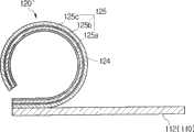
卷起叶片120′和120″的其它示例示出在图5A和图5B中。在图5A和图5B中示出的卷起叶片120′和120″具有两个层,卷起叶片120′的两个层中的一个层由压电驱动层125形成,卷起叶片120″的两个层中的一个层由压电驱动层127形成。Other examples of roll-up
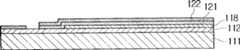
图5A中示出的卷起叶片120′具有在其底部的绝缘层124和形成在绝缘层124的顶表面上的压电驱动层125。卷起叶片120′的底部绝缘层124具有残余压应力,并且其顶部压电驱动层125具有残余拉应力,从而卷起叶片120′可卷起。图5B中示出的卷起叶片120″具有在其底部的压电驱动层127和形成在压电驱动层127的顶表面上的绝缘层126。卷起叶片120″的底部压电驱动层127具有残余压应力,而其顶部绝缘层126具有残余拉应力,从而卷起叶片120″可卷起。这里,压电驱动层125被构造为由第一电极层125a、压电层125b和第二电极层125c构成的层结构,而压电驱动层127被构造为由第一电极层127a、压电层127b和第二电极层127c构成的层结构。因此,透明的基础绝缘层117形成在底座110的透明电极112上,图5B中示出的卷起叶片120″接触透明的基础绝缘层117,以防止压电驱动层127的第二压电层127c接触透明的电极112。The turn-up
电压被施加给与底座110的透明电极112最近的卷起叶片120′的压电驱动层125的电极层125c,以产生使卷起叶片120′打开的静电力;电压被施加给与底座110的透明电极112最近的卷起叶片120″的压电驱动层127的电极层127c,以产生使卷起叶片120″打开的静电力。即,两个电极层125a和125c中较接近透明电极112的电极层125c被用作电极,以在电极层125c和透明电极112之间产生静电力,并且在压电驱动层125的电极层125c和另一电极层125a之间产生压电驱动力;两个电极层127a和127c中较接近透明电极112的电极层127c被用作电极,以在电极层127c和透明电极112之间产生静电力,并在压电驱动层127的电极层127c和另一电极层127a之间产生压电驱动力。The voltage is applied to the
例如,当压电驱动层125在绝缘层124的顶表面上时,如图5A所示,电压被施加到透明电极112、第一电极层125a和第二电极层125c上,从而在压电驱动层125的第二电极层125c和底座110的透明电极112之间产生静电力,而在压电驱动层125的第一电极层125a和第二电极层125c之间产生压电驱动力。例如,当+5V电压被施加给压电驱动层125的第二电极层125c时,透明电极112和第一电极层125a被设为0V。当上述电压被施加给压电驱动层125和透明电极112时,在透明电极112和第二电极层125c之间产生静电力,并且在第一电极层125a和第二电极层125c之间产生压电驱动力,从而卷起叶片120′同时被压电驱动力和静电力驱动。在上述解释中,被施加给透明电极112、第一电极层125a和第二电极层125c的电压仅是示例性的,目的不在于限制。所述电压可按照各种方法被施加到上述层上。For example, when the
此外,当压电驱动层127在绝缘层126之下时,如图5B所示,电压被施加给透明电极112、第一电极层127a和第二电极层127c,从而在压电驱动层127的第二电极层127c和透明电极112之间产生静电力,在压电驱动层127的第一电极层127a和第二电极层127c之间产生压电驱动力。当压电驱动层125的一个电极层125c被用作如上所述的用于静电驱动的电极时,所述静电力和压电驱动力可同时被用于控制卷起叶片120′的打开程度;当压电驱动层127的一个电极层127c被用作如上所述的用于静电驱动的电极时,所述静电力和压电驱动力可同时被用于控制卷起叶片120″的打开程度。In addition, when the
如上所述,如果卷起叶片120′被构造成具有压电驱动层125,则在卷起叶片120′和透明电极112之间操作的静电力和压电驱动层125的压电驱动力可被用于打开卷起叶片120′;如果卷起叶片120″被构造成具有压电驱动层127,则在卷起叶片120″和透明电极112之间操作的静电力和压电驱动层127的压电驱动力可被用于打开卷起叶片120″。因此,可减小用于操作卷起叶片120′和120″的电压的大小。As described above, if the rolling blade 120' is configured with the
再次参照图1A、图1B、图1C、图2A和图2B,控制器150将预定的电压施加给所述多个卷起叶片120的每个的顶部电极层122和底座110的透明电极112,从而卷起部分120的运动部分120b展开,以接触透明部分113。控制器150可控制被施加到所述多个卷起叶片120和底座110上的电压的大小,从而控制器150可以按照多个步骤控制每个卷起叶片120的运动部分120b的打开程度。光可穿过的透明部分113的区域相应于卷起叶片120的运动部分120b的打开程度而改变,从而穿过透明部分113的光的量相应于卷起叶片120的运动部分120b的打开程度而改变。因此,所述多个卷起叶片120可起可变光阑的作用。1A, 1B, 1C, 2A and 2B again, the
下面,将参照图1A、图1B、图1C、图2A和图2B详细解释根据本发明总体构思的第一实施例的具有可变光阑功能的微型快门100的操作。Hereinafter, the operation of the
当控制器150不将电压施加给所述多个卷起叶片120时,如图1A和图2A所示,所述多个卷起叶片保持其运动部分120b在其固定部分120a上卷起的状态。底座110的透明部分113完全打开,从而最大量的光穿过透明部分113。When the
当控制器150在这种状态下接收快门操作信号时,控制器150将快门电压施加给所述多个卷起叶片120的每个的顶部电极层122和底座110的透明电极112。当快门电压被施加到所述多个卷起叶片120和透明电极112之间时,卷起叶片120的运动部分120b通过在卷起叶片120的运动部分120b和透明电极112之间产生的静电力逐渐打开,以遮盖透明部分113,如图1B和图2B所示。当所述多个卷起叶片120的运动部分120b完全遮盖底座110的透明部分113时,光被阻挡。这里,快门电压指能够完全打开所述多个卷起叶片120的运动部分120b以使其紧密地接触透明部分113的电压的大小。When the
当控制器150中断被施加给所述多个卷起叶片120的快门电压时,所述多个卷起叶片120的运动部分120b由于其残余应力而沿逆时针方向自己卷起,并位于所述多个卷起叶片120的固定部分120a之上,如图1A和图2A所示。结果,底座110的透明部分113被打开,从而光可穿过被打开的透明部分113。When the
此外,当根据本发明的示例性实施例的微型快门100被用作可变光阑时,控制器150在所述多个卷起叶片120的顶部电极层122和透明电极112之间施加比快门电压小的电压。当电压被施加到所述多个卷起叶片120和透明电极112之间时,卷起叶片120的运动部分120b遮盖透明部分113的与被施加的电压的大小对应的一部分,以在透明部分113的中心形成基本上为圆形的可变光阑开口101,如图1C所示。光通过可变光阑开口101穿过透明部分113。控制器150控制被施加到所述多个卷起叶片120上的电压的大小,以调节可变光阑开口101的尺寸。因此,控制器150可控制穿过透明部分113的光的量。此外,控制器150可控制被施加到所述多个卷起叶片120上的电压的大小,以至少分三步调节所述多个卷起叶片120的打开程度,即,第一步,卷起叶片120完全卷起;第二步,卷起叶片120部分打开;第三步,卷起叶片120完全打开。In addition, when the micro-shutter 100 according to the exemplary embodiment of the present invention is used as an iris diaphragm, the
根据本发明的第一示例性实施例的具有可变光阑功能的微型快门100具有按照薄膜形状形成的所述多个卷起叶片120,从而微型快门100可被低的电功率驱动。因此,电功率的消耗降低,并且其控制容易。此外,薄膜卷起叶片120具有小的惯性质量,从而卷起叶片120可高速操作。如果所述多个卷起叶片120被布置成规则的多边形,则所述多个卷起叶片120可形成与圆形相似的可变光阑开口101。The
在上述描述中,静电力被用作调节卷起叶片120的打开程度的驱动力。另一种方案是,磁力可被用作调节卷起叶片120的打开程度的驱动力。卷起叶片120和底座110可被构造为使得磁力被选择性地在叶片120和底座110之间产生。In the above description, electrostatic force is used as a driving force for adjusting the degree of opening of the
如图6所示,根据本发明的示例性实施例的微型快门200可具有多个卷起叶片220,两个相邻的卷起叶片220彼此局部重叠。所述多个卷起叶片220可形成多层。例如,所述多个卷起叶片220中的奇数卷起叶片n1和n3形成在第一层中,其中的偶数卷起叶片n2和n4形成在第二层中。如图6所示,靠近形成在第一层和第二层中的卷起叶片220的两侧的部分221彼此重叠,从而防止光在两个相邻的卷起叶片220之间穿过。As shown in FIG. 6, the
另一种方案是,虽然未在图6中示出,但是所述多个卷起叶片220可形成三层,即,第一层由其奇数卷起叶片构成,第二层由其偶数卷起叶片构成,第三层由遮盖中心的中心遮盖卷起叶片(未显示)构成,所述多个卷起叶片220的顶点集中在所述中心。此外,所述多个卷起叶片220可形成为使得所述卷起叶片220的每个形成与其它卷起叶片220不同的层。Alternatively, although not shown in FIG. 6 , the plurality of rolled
图7A至图7C示出了根据本发明的第二示例性实施例的具有可变光阑功能的具有24个卷起叶片320的微型快门300。即,所述多个卷起叶片320布置成规则的二十四边形(icosikaitetragon或icositetragon)。在图7A中,底座110的透明部分113被打开。在图7C中,所述多个卷起叶片320遮盖透明部分113,以阻挡光。在图7B中,比快门电压低的电压被施加到所述多个卷起叶片320上,从而卷起叶片320形成可变光阑开口301,该可变光阑开口301的直径比被完全打开的透明部分113的直径小。图7B的可变光阑开口301比图1C中的可变光阑开口101更加类似于圆形。所述多个卷起叶片320的每个的结构与根据本发明总体构思的第一实施例的微型开口100的卷起叶片120的结构基本上相同,因此,将不重复对其进行详细解释。7A to 7C illustrate a
控制器150将电压施加到所述多个卷起叶片320,以分多个步骤控制卷起叶片320的打开程度。当控制器150将快门电压施加给所述多个卷起叶片320时,所有的卷起叶片320打开,以遮盖圆形透明部分113,从而阻挡光。当控制器150中断快门电压时,所述多个卷起部分320的每个的运动部分320b自己卷起,然后位于其固定部分320b之上。因此,基座110的透明部分113被完全打开。The
当控制器150将比快门电压小的电压施加到所述多个卷起叶片320时,所述多个卷起叶片320在透明部分113的中心形成可变光阑开口301,如图7B所示。因此,光经可变光阑开口301穿过透明部分113。控制器150控制被施加到所述多个卷起叶片320上的电压的大小,从而可变光阑开口301的尺寸几乎线性地改变。因此,根据本发明的示例性实施例的微型快门300可被用作可变光阑。When the
图8A和图8B是示出根据本发明总体构思的第三示例性实施例的具有可变光阑功能的微型快门400的透视图。8A and 8B are perspective views illustrating a
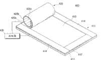
参照图8A和图8B,根据本发明总体构思的第三实施例的具有可变光阑功能的微型快门400包括底座410、卷起叶片420和控制器430。Referring to FIGS. 8A and 8B , a
底座410包括透明基底411和形成在透明基底411的顶表面上的透明电极412。透明部分413形成在透明电极412的顶表面上。在该实施例中,透明部分413基本上按照矩形形成。然而,透明部分413可按照各种形状(例如,圆形、三角形、椭圆形、梯形、多边形、不规则的封闭图案等)形成。此外,不透明部分414可在透明电极412的顶表面上形成在透明部分413的外侧,以防止光穿过。The
卷起叶片420形成为选择性地遮盖底座410的透明部分413,并防止光穿过透明部分413。即,当没有驱动力被施加到卷起叶片420上时,卷起叶片420保持卷起的状态。当驱动力被施加时,卷起叶片420打开以遮盖透明部分413,从而防止光穿过透明部分413。卷起叶片420形成两层,并包括:固定部分420a,被固定到底座410上,在透明部分413的一侧;运动部分420b,朝着固定部分420a卷起,如图8A所示。此外,卷起叶片420可具有与卷起叶片420卷起和打开的方向垂直地形成在运动部分420b上的多个褶420c。The rolling
控制器430将电压施加到卷起叶片420上,以分多个步骤控制卷起叶片420的打开程度。The
除了一个卷起叶片420闭合和打开透明部分413以外,根据该示例性实施例的微型开关400的结构和操作与上述根据第一实施例的微型开关100的那些结构和操作基本上相同。因此,不重复对其进行详细解释。The structure and operation of the
图9A至图9C是示出根据本发明总体构思的第四实施例的具有可变光阑功能的微型快门500的透视图。9A to 9C are perspective views illustrating a
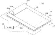
参照图9A至图9C,根据本发明总体构思的第四实施例的具有可变光阑功能的微型快门500包括底座510、一对卷起叶片520和530以及控制器550。Referring to FIGS. 9A to 9C , a
底座510包括透明基底511和形成在透明基底511的顶表面上的透明电极512。透明部分513基本上按照矩形形成在透明电极412的顶表面上。不透明部分540可在透明电极512的顶表面上形成在透明部分513的外侧,以防止光穿过。底座510的结构与根据第一实施例的微型开关100的底座的结构基本上相同,因此,将不重复对其进行详细描述。The
所述一对卷起叶片520和530被设置为在透明电极512上在透明部分513的相对两侧互相面对,以遮盖透明部分513。所述一对卷起叶片520和530的每个具有完全遮盖透明部分513的尺寸。所述一对卷起叶片520和530的结构和操作与根据第一示例性实施例的微型快门100的卷起叶片120的结构和操作基本相同;因此,将不重复对其进行详细解释。The pair of rolling
控制器550将电压施加到所述一对卷起叶片520和530,以分多个步骤控制所述一对卷起叶片520和530的打开程度。在图9A中,控制器550将快门电压施加到右侧卷起叶片530,而没有电压被施加到左侧卷起叶片520。那么,右侧卷起叶片530打开,以遮盖透明部分513,从而光不能穿过透明部分513。在图9C中,控制器550将快门电压施加给左侧卷起叶片520,而没有电压被施加给右侧卷起叶片530。那么,左侧卷起叶片520打开以遮盖透明部分513,从而光不能穿过透明部分513。The
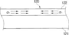
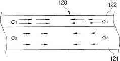
图9B是示出根据该示例性实施例的微型快门500的操作的透视图。控制器550将预定的电压施加给所述一对卷起叶片520和530,从而所述一对卷起叶片520和530不互相接触并且彼此分开预定间隙W。那么,在所述一对卷起叶片520和530之间形成缝隙501,光可穿过缝隙501。接着,控制器550控制所述一对卷起叶片520和530,从而缝隙501从透明部分513的一侧运动到透明部分513的相对侧。即,当控制器550增大被施加到一个卷起叶片520或530上的电压的大小而减小被施加到另一卷起叶片530或520上的电压的大小时,缝隙沿着透明部分513运动。因此,根据该实施例的微型快门500可被用作高速缝隙焦平面快门(high-speed slit focal plane shutter)。FIG. 9B is a perspective view showing the operation of the
图10是示意性地示出根据本发明的示例性实施例的具有具有可变光阑功能的微型快门100的微型相机模块600的截面图。FIG. 10 is a cross-sectional view schematically illustrating a
参照图10,微型相机模块600包括微型快门100、透镜单元700和图像传感器800。Referring to FIG. 10 , the
微型快门100操作所述多个卷起叶片120,以控制进入到图像传感器800的光的量,并且还如上所述起到可变光阑的作用。盖子102可设置在微型快门100的底座110上,以保护所述多个卷起叶片120。微型快门100的底座110的透明基底111可与用于调节穿过透明部分113的光的光学元件(例如,滤光器、透镜等)一体地形成。The micro-shutter 100 operates the plurality of rolling
透镜单元700允许穿过微型快门100的光聚焦在图像传感器800上。虽然未示出,但是其它的透镜单元700可被设置在微型快门100之上。The
图像传感器800具有多个象素,从而用户可拍摄具有用户想要的分辨率的照片。例如,可使用2百万至8百万象素范围的图像传感器800。因此,当根据本发明总体构思的实施例的微型快门100操作时,图像传感器800形成用户想要的图像。The
下面,将参照图11A至图11E详细地解释制造根据本发明总体构思的实施例的具有可变光阑功能的微型快门100的方法。当制造根据本发明的示例性实施例的具有可变光阑功能的微型快门100时,可使用晶片级半导体制造工艺(wafer level semiconductor fabrication process)。为了方便解释,图11A至图11E仅示出了形成一个卷起叶片120的过程。Hereinafter, a method of manufacturing the
首先,准备透明基底111。在透明基底111的顶表面上形成透明电极112。例如玻璃、石英、塑料、硅石等的材料可被用作透明基底111。例如铟锡氧化物(ITO)、电活性聚合物(electro active substrate)等的材料可被用于形成透明电极112。First, a
牺牲层118被图案化并形成在透明电极112上。牺牲层118可按照与卷起叶片120的运动部分120b相应的形状形成。牺牲层118可由例如光刻胶、聚对二甲苯、等离子增强化学气相沉积无定形硅(PECVDa-Si)、多晶硅等的材料形成。A
用作卷起叶片120的底部绝缘层的绝缘层121被图案化并形成在牺牲层的顶表面上。用作卷起叶片120的固定部分120a的绝缘层121的一部分121a形成在透明电极112上。绝缘层121可由具有光学黑特性的材料形成。绝缘层121可由例如PECVD、Si3N4、SiO2、聚对二甲苯等的材料形成。An insulating
接着,用作卷起叶片120的顶部电极层的电极层122被图案化并形成在绝缘层121的顶表面上。电极层122可由金属或其它电极材料形成。例如,电极层122可由例如Cr、Al、Au、Mo、Cu等的材料形成。此外,电极层122可由具有光学黑特性的材料形成。此外,电极层122和绝缘层121的残余应力被适当地调节,以使得具有绝缘层121和电极层122的卷起叶片120可自己卷起。Next, an
最后,通过等离子体蚀刻工艺、气相蚀刻工艺等去除牺牲层118。然后,形成卷起叶片120的绝缘层121和电极层122自己卷起,即,由于其残余应力而沿逆时针方向自己卷起,如图11E所示。Finally, the
当使用用于制造微型快门100的晶片级半导体制造工艺时,微型快门100的卷起叶片120的数量可通过改变半导体制造工艺中的光掩模的设计而被容易地调整。因此,微型快门100的卷起叶片120的数量可容易地增加。此外,因为使用半导体制造工艺,所以微型快门100的制造容易,并且微型快门100的生产率提高。此外,微型快门100可与晶片级透镜阵列或晶片级图像传感器模块一体地制造。When using a wafer-level semiconductor manufacturing process for manufacturing the micro-shutter 100, the number of rolled
虽然已经示出并描述了本发明总体构思的一些示例性实施例,但是本领域技术人员应当理解,在不脱离本发明构思的原理和精神的情况下,可对这些实施例进行改变,本发明构思的范围由权利要求及其等同物限定。Although some exemplary embodiments of the general inventive concept have been shown and described, it should be understood by those skilled in the art that changes may be made to these embodiments without departing from the principles and spirit of the inventive concept. The scope of the concept is defined by the claims and their equivalents.
Claims (25)

Applications Claiming Priority (3)
| Application Number | Priority Date | Filing Date | Title |
|---|---|---|---|
| KR10-2007-0122918 | 2007-11-29 | ||
| KR1020070122918 | 2007-11-29 | ||
| KR1020070122918AKR100933294B1 (en) | 2007-11-29 | 2007-11-29 | Shutter and micro camera module having same |
Publications (2)
| Publication Number | Publication Date |
|---|---|
| CN101446738Atrue CN101446738A (en) | 2009-06-03 |
| CN101446738B CN101446738B (en) | 2012-04-04 |
Family
ID=40675817
Family Applications (1)
| Application Number | Title | Priority Date | Filing Date |
|---|---|---|---|
| CN2008101339760AExpired - Fee RelatedCN101446738B (en) | 2007-11-29 | 2008-07-18 | Micro shutter having iris function, method for manufacturing the same, and micro camera module |
Country Status (4)
| Country | Link |
|---|---|
| US (2) | US8061910B2 (en) |
| JP (1) | JP5450990B2 (en) |
| KR (1) | KR100933294B1 (en) |
| CN (1) | CN101446738B (en) |
Cited By (11)
| Publication number | Priority date | Publication date | Assignee | Title |
|---|---|---|---|---|
| CN102540503A (en)* | 2010-12-17 | 2012-07-04 | 三星电子株式会社 | Light screening apparatus and electronic device including same |
| CN104662473A (en)* | 2012-03-07 | 2015-05-27 | 新加坡国立大学 | A MEMS iris diaphragm for an optical system and method for adjusting a size of an aperture thereof |
| CN105511201A (en)* | 2016-02-29 | 2016-04-20 | 联想(北京)有限公司 | Camera module and electronic equipment |
| CN107355730A (en)* | 2017-07-17 | 2017-11-17 | 上海小糸车灯有限公司 | Car light MEMS intelligent illuminating systems, vehicle lamp assembly and automobile |
| CN108627971A (en)* | 2018-03-22 | 2018-10-09 | 无锡微奥科技有限公司 | A kind of MEMS transmission-types Shutter array structures |
| CN109882798A (en)* | 2019-04-02 | 2019-06-14 | 华域视觉科技(上海)有限公司 | Transmission-type MEMS chip, split transmission-type chip, lighting system and automobile |
| CN110568607A (en)* | 2019-08-02 | 2019-12-13 | 南京航空航天大学 | A Piezoelectrically Actuated Integrated Aperture |
| WO2021057646A1 (en)* | 2019-09-26 | 2021-04-01 | 维沃移动通信有限公司 | Camera module and electronic device |
| CN112666700A (en)* | 2020-11-23 | 2021-04-16 | 山东大学 | Vane type rapid mechanical optical switch based on piezoelectric drive |
| CN115453801A (en)* | 2022-08-24 | 2022-12-09 | 清华大学 | Assembly-free ultra-miniature camera and its molding manufacturing method based on additive manufacturing |
| CN116088248A (en)* | 2021-11-05 | 2023-05-09 | 宁波舜宇光电信息有限公司 | Electrostatic iris diaphragm, camera module and method for controlling light inlet quantity of camera module |
Families Citing this family (12)
| Publication number | Priority date | Publication date | Assignee | Title |
|---|---|---|---|---|
| KR101557485B1 (en)* | 2008-12-09 | 2015-10-06 | 삼성전자 주식회사 | Micro shutter device and manufacturing method thereof |
| US8576469B2 (en) | 2009-05-13 | 2013-11-05 | Samsung Electronics Co., Ltd. | Light screening apparatus including roll-up actuators |
| KR20110081700A (en)* | 2010-01-08 | 2011-07-14 | 삼성전자주식회사 | Light shielding device and manufacturing method thereof |
| KR101878719B1 (en)* | 2011-06-24 | 2018-07-16 | 삼성전자 주식회사 | Light screening apparatus and its fabricating method |
| KR102065116B1 (en) | 2011-07-14 | 2020-01-10 | 삼성전자주식회사 | Optical transmittance adjusting device, Image apparatus and Method for manufacturing the device |
| KR101288255B1 (en)* | 2011-11-10 | 2013-07-26 | 삼성전기주식회사 | Camera module |
| EP2801089A1 (en)* | 2012-01-03 | 2014-11-12 | Koninklijke Philips N.V. | Electrostatically controllable device |
| US9217857B2 (en) | 2013-03-12 | 2015-12-22 | Pixtronix, Inc. | Multi-state shutter assemblies having segmented drive electrode sets |
| US10077885B2 (en)* | 2015-06-15 | 2018-09-18 | Martin Professional Aps | Iris diaphragm system |
| US10288191B2 (en) | 2015-12-23 | 2019-05-14 | University Of Louisville Research Foundation, Inc. | Bilayer microvalve arrays for pneumatic and fluidic applications |
| DE102020123024B4 (en) | 2020-09-03 | 2024-12-24 | Universität Kassel | mirror shutter system |
| US12114127B2 (en)* | 2021-09-17 | 2024-10-08 | Apple Inc. | Dynamic valve for an electronic device |
Family Cites Families (29)
| Publication number | Priority date | Publication date | Assignee | Title |
|---|---|---|---|---|
| US3989357A (en)* | 1974-02-01 | 1976-11-02 | Kalt Charles G | Electro-static device with rolling electrode |
| US4234245A (en)* | 1977-04-22 | 1980-11-18 | Rca Corporation | Light control device using a bimorph element |
| US4266339A (en)* | 1979-06-07 | 1981-05-12 | Dielectric Systems International, Inc. | Method for making rolling electrode for electrostatic device |
| JPS5642218A (en)* | 1979-09-17 | 1981-04-20 | Sony Corp | Diaphragm mechanism of image pickup device |
| JPS59148003A (en)* | 1983-02-14 | 1984-08-24 | Matsushita Electric Ind Co Ltd | Piezoelectric light shielding device |
| JPS61503057A (en)* | 1984-08-21 | 1986-12-25 | シンプソン,ジヨ−ジ ア−ル. | Electrostatically actuated binary device array |
| JPS61140327U (en)* | 1985-02-22 | 1986-08-30 | ||
| WO1989001217A1 (en)* | 1987-07-24 | 1989-02-09 | Battelle Memorial Institute | Device for unrolling on a substrate a material in sheet form rolled elastically in a spiral and use of said device |
| CA2058396C (en)* | 1990-12-25 | 1995-05-30 | Osamu Sato | Light-quantity control device |
| US5233459A (en)* | 1991-03-06 | 1993-08-03 | Massachusetts Institute Of Technology | Electric display device |
| JPH04312436A (en)* | 1991-04-11 | 1992-11-04 | Olympus Optical Co Ltd | Endoscope |
| JPH05119366A (en)* | 1991-10-24 | 1993-05-18 | Olympus Optical Co Ltd | Diaphragm controller for solid-state image pickup device |
| CA2163981C (en)* | 1993-07-02 | 2002-12-31 | Carl O. Bozler | Spatial light modulator |
| JP3636252B2 (en)* | 1996-05-24 | 2005-04-06 | 富士写真フイルム株式会社 | Variable aperture device and endoscope |
| US5781331A (en)* | 1997-01-24 | 1998-07-14 | Roxburgh Ltd. | Optical microshutter array |
| JPH112764A (en) | 1997-06-10 | 1999-01-06 | Sharp Corp | Optical switching device, display device, and method of manufacturing optical switching device |
| JPH1172722A (en)* | 1997-08-28 | 1999-03-16 | Sharp Corp | Optical switching device, display device, and manufacturing method thereof |
| JPH11167078A (en)* | 1997-12-05 | 1999-06-22 | Nikon Corp | Optical shutter and its manufacture |
| US6067183A (en)* | 1998-12-09 | 2000-05-23 | Eastman Kodak Company | Light modulator with specific electrode configurations |
| US6226116B1 (en) | 1999-11-30 | 2001-05-01 | Eastman Kodak Company | Magnetic micro-shutters |
| EP1107051A1 (en)* | 1999-11-30 | 2001-06-13 | Eastman Kodak Company | One time use camera using magnetic micro-shutter as an exposure frame counter |
| US6313937B1 (en)* | 1999-11-30 | 2001-11-06 | Eastman Kodak Company | Electrically actuated magnetic micro-shutters |
| US6443637B1 (en)* | 2000-03-15 | 2002-09-03 | Eastman Kodak Company | Camera with electrostatic light valve that functions as diaphragm |
| JP4806850B2 (en)* | 2001-01-24 | 2011-11-02 | パナソニック株式会社 | Actuator |
| ITTO20010250A1 (en)* | 2001-03-16 | 2002-09-16 | Fiat Ricerche | ELECTROSTATIC CONTROL OPTICAL MICRO-SHUTTER DEVICE WITH FIXED NON-TRANSPARENT ELECTRODE. |
| US6586738B2 (en)* | 2001-04-13 | 2003-07-01 | Mcnc | Electromagnetic radiation detectors having a micromachined electrostatic chopper device |
| JP4147214B2 (en)* | 2004-10-08 | 2008-09-10 | キヤノン株式会社 | Light amount adjusting device and optical apparatus |
| CA2537569C (en)* | 2005-02-24 | 2014-04-29 | National Research Council Of Canada | Microblinds and a method of fabrication thereof |
| KR100773018B1 (en) | 2007-02-16 | 2007-11-02 | 한국과학기술원 | Micro Shutter Device Using Polymer Pattern as Mold, Micro Shutter Device Using Polymer Pattern as Mold |
- 2007
- 2007-11-29KRKR1020070122918Apatent/KR100933294B1/ennot_activeExpired - Fee Related
- 2008
- 2008-06-06USUS12/134,324patent/US8061910B2/enactiveActive
- 2008-07-03JPJP2008174606Apatent/JP5450990B2/ennot_activeExpired - Fee Related
- 2008-07-18CNCN2008101339760Apatent/CN101446738B/ennot_activeExpired - Fee Related
- 2011
- 2011-10-11USUS13/270,723patent/US8147150B2/ennot_activeExpired - Fee Related
Cited By (15)
| Publication number | Priority date | Publication date | Assignee | Title |
|---|---|---|---|---|
| CN102540503A (en)* | 2010-12-17 | 2012-07-04 | 三星电子株式会社 | Light screening apparatus and electronic device including same |
| CN104662473A (en)* | 2012-03-07 | 2015-05-27 | 新加坡国立大学 | A MEMS iris diaphragm for an optical system and method for adjusting a size of an aperture thereof |
| CN105511201A (en)* | 2016-02-29 | 2016-04-20 | 联想(北京)有限公司 | Camera module and electronic equipment |
| CN105511201B (en)* | 2016-02-29 | 2019-01-15 | 联想(北京)有限公司 | A kind of camera module and electronic equipment |
| CN107355730A (en)* | 2017-07-17 | 2017-11-17 | 上海小糸车灯有限公司 | Car light MEMS intelligent illuminating systems, vehicle lamp assembly and automobile |
| CN108627971A (en)* | 2018-03-22 | 2018-10-09 | 无锡微奥科技有限公司 | A kind of MEMS transmission-types Shutter array structures |
| CN109882798A (en)* | 2019-04-02 | 2019-06-14 | 华域视觉科技(上海)有限公司 | Transmission-type MEMS chip, split transmission-type chip, lighting system and automobile |
| CN109882798B (en)* | 2019-04-02 | 2024-03-12 | 华域视觉科技(上海)有限公司 | Transmission type MEMS chip, split transmission type chip, lighting system and automobile |
| CN110568607A (en)* | 2019-08-02 | 2019-12-13 | 南京航空航天大学 | A Piezoelectrically Actuated Integrated Aperture |
| CN110568607B (en)* | 2019-08-02 | 2021-05-11 | 南京航空航天大学 | Piezoelectricity driven integral type diaphragm |
| WO2021057646A1 (en)* | 2019-09-26 | 2021-04-01 | 维沃移动通信有限公司 | Camera module and electronic device |
| CN112666700A (en)* | 2020-11-23 | 2021-04-16 | 山东大学 | Vane type rapid mechanical optical switch based on piezoelectric drive |
| CN112666700B (en)* | 2020-11-23 | 2022-04-22 | 山东大学 | Vane type rapid mechanical optical switch based on piezoelectric drive |
| CN116088248A (en)* | 2021-11-05 | 2023-05-09 | 宁波舜宇光电信息有限公司 | Electrostatic iris diaphragm, camera module and method for controlling light inlet quantity of camera module |
| CN115453801A (en)* | 2022-08-24 | 2022-12-09 | 清华大学 | Assembly-free ultra-miniature camera and its molding manufacturing method based on additive manufacturing |
Also Published As
| Publication number | Publication date |
|---|---|
| JP2009134248A (en) | 2009-06-18 |
| JP5450990B2 (en) | 2014-03-26 |
| US8061910B2 (en) | 2011-11-22 |
| KR100933294B1 (en) | 2009-12-22 |
| KR20090055996A (en) | 2009-06-03 |
| US20120027397A1 (en) | 2012-02-02 |
| US8147150B2 (en) | 2012-04-03 |
| US20090142050A1 (en) | 2009-06-04 |
| CN101446738B (en) | 2012-04-04 |
Similar Documents
| Publication | Publication Date | Title |
|---|---|---|
| CN101446738B (en) | Micro shutter having iris function, method for manufacturing the same, and micro camera module | |
| JP5520898B2 (en) | Method for manufacturing MEMS device for controlling air gap | |
| US9019390B2 (en) | Optical image stabilization using tangentially actuated MEMS devices | |
| KR101158200B1 (en) | Optical Image Stabilizer and Method of manufacturing the same | |
| US8576469B2 (en) | Light screening apparatus including roll-up actuators | |
| CN103180239B (en) | Piezoelectric based microelectromechanical lens actuation system | |
| TWI576635B (en) | Angled facets for display devices | |
| JP2006099104A (en) | Method for forming a pre-structure for a MEMS system | |
| TW200938930A (en) | MEMS devices requiring no mechanical support | |
| WO2012142849A1 (en) | Display device provided with mems light valve and forming method thereof | |
| JP4266661B2 (en) | Photomask for near-field exposure | |
| CN102841482A (en) | Light screening apparatus and fabricating method thereof | |
| US20110170158A1 (en) | Optical shuttering device and method of manufacturing the same | |
| US8616791B2 (en) | Rotationally deployed actuator devices | |
| JP2009113128A (en) | Micro oscillating device and method of manufacturing micro oscillating device | |
| CN114105081A (en) | Micro Scanning Mirror | |
| JP2006154315A (en) | Electrostatic comb-type oscillator device and manufacturing method thereof | |
| KR101715878B1 (en) | Light screening device and manufacturing method thereof | |
| TW201238880A (en) | Apparatus and method for supporting a mechanical layer | |
| JP6397478B2 (en) | Control of arc motion in electrostatic actuators. | |
| JP5521553B2 (en) | Actuator mechanism | |
| JP5171489B2 (en) | Method of manufacturing structure by anisotropic etching, and silicon substrate with etching mask | |
| JP4544574B2 (en) | Optical deflection device | |
| JP4360761B2 (en) | Light modulator | |
| KR101184677B1 (en) | Electromagnetic Flapping Actuator |
Legal Events
| Date | Code | Title | Description |
|---|---|---|---|
| C06 | Publication | ||
| PB01 | Publication | ||
| C10 | Entry into substantive examination | ||
| SE01 | Entry into force of request for substantive examination | ||
| C14 | Grant of patent or utility model | ||
| GR01 | Patent grant | ||
| CF01 | Termination of patent right due to non-payment of annual fee | Granted publication date:20120404 | |
| CF01 | Termination of patent right due to non-payment of annual fee |