CN101443261B - flow meter assembly - Google Patents
flow meter assemblyDownload PDFInfo
- Publication number
- CN101443261B CN101443261BCN2005800522744ACN200580052274ACN101443261BCN 101443261 BCN101443261 BCN 101443261BCN 2005800522744 ACN2005800522744 ACN 2005800522744ACN 200580052274 ACN200580052274 ACN 200580052274ACN 101443261 BCN101443261 BCN 101443261B
- Authority
- CN
- China
- Prior art keywords
- fluid
- flow counter
- connector assembly
- beverage dispenser
- manifold
- Prior art date
- Legal status (The legal status is an assumption and is not a legal conclusion. Google has not performed a legal analysis and makes no representation as to the accuracy of the status listed.)
- Active
Links
Images


Classifications
- B—PERFORMING OPERATIONS; TRANSPORTING
- B67—OPENING, CLOSING OR CLEANING BOTTLES, JARS OR SIMILAR CONTAINERS; LIQUID HANDLING
- B67D—DISPENSING, DELIVERING OR TRANSFERRING LIQUIDS, NOT OTHERWISE PROVIDED FOR
- B67D1/00—Apparatus or devices for dispensing beverages on draught
- B67D1/08—Details
- B67D1/12—Flow or pressure control devices or systems, e.g. valves, gas pressure control, level control in storage containers
- B67D1/1202—Flow control, e.g. for controlling total amount or mixture ratio of liquids to be dispensed
- B67D1/1234—Flow control, e.g. for controlling total amount or mixture ratio of liquids to be dispensed to determine the total amount
- B67D1/1243—Flow control, e.g. for controlling total amount or mixture ratio of liquids to be dispensed to determine the total amount comprising flow or pressure sensors, e.g. for controlling pumps
- B—PERFORMING OPERATIONS; TRANSPORTING
- B67—OPENING, CLOSING OR CLEANING BOTTLES, JARS OR SIMILAR CONTAINERS; LIQUID HANDLING
- B67D—DISPENSING, DELIVERING OR TRANSFERRING LIQUIDS, NOT OTHERWISE PROVIDED FOR
- B67D1/00—Apparatus or devices for dispensing beverages on draught
- B67D1/08—Details
- B67D1/0855—Details concerning the used flowmeter
- B—PERFORMING OPERATIONS; TRANSPORTING
- B67—OPENING, CLOSING OR CLEANING BOTTLES, JARS OR SIMILAR CONTAINERS; LIQUID HANDLING
- B67D—DISPENSING, DELIVERING OR TRANSFERRING LIQUIDS, NOT OTHERWISE PROVIDED FOR
- B67D1/00—Apparatus or devices for dispensing beverages on draught
- B67D1/08—Details
- B67D1/12—Flow or pressure control devices or systems, e.g. valves, gas pressure control, level control in storage containers
- B67D1/1202—Flow control, e.g. for controlling total amount or mixture ratio of liquids to be dispensed
- B67D1/1204—Flow control, e.g. for controlling total amount or mixture ratio of liquids to be dispensed for ratio control purposes
- B67D1/1211—Flow rate sensor
- B—PERFORMING OPERATIONS; TRANSPORTING
- B67—OPENING, CLOSING OR CLEANING BOTTLES, JARS OR SIMILAR CONTAINERS; LIQUID HANDLING
- B67D—DISPENSING, DELIVERING OR TRANSFERRING LIQUIDS, NOT OTHERWISE PROVIDED FOR
- B67D2210/00—Indexing scheme relating to aspects and details of apparatus or devices for dispensing beverages on draught or for controlling flow of liquids under gravity from storage containers for dispensing purposes
- B67D2210/00028—Constructional details
- B67D2210/00047—Piping
- B67D2210/0006—Manifolds
- Y—GENERAL TAGGING OF NEW TECHNOLOGICAL DEVELOPMENTS; GENERAL TAGGING OF CROSS-SECTIONAL TECHNOLOGIES SPANNING OVER SEVERAL SECTIONS OF THE IPC; TECHNICAL SUBJECTS COVERED BY FORMER USPC CROSS-REFERENCE ART COLLECTIONS [XRACs] AND DIGESTS
- Y10—TECHNICAL SUBJECTS COVERED BY FORMER USPC
- Y10T—TECHNICAL SUBJECTS COVERED BY FORMER US CLASSIFICATION
- Y10T137/00—Fluid handling
- Y10T137/2496—Self-proportioning or correlating systems
- Y10T137/2708—Plural sensors
- Y—GENERAL TAGGING OF NEW TECHNOLOGICAL DEVELOPMENTS; GENERAL TAGGING OF CROSS-SECTIONAL TECHNOLOGIES SPANNING OVER SEVERAL SECTIONS OF THE IPC; TECHNICAL SUBJECTS COVERED BY FORMER USPC CROSS-REFERENCE ART COLLECTIONS [XRACs] AND DIGESTS
- Y10—TECHNICAL SUBJECTS COVERED BY FORMER USPC
- Y10T—TECHNICAL SUBJECTS COVERED BY FORMER US CLASSIFICATION
- Y10T29/00—Metal working
- Y10T29/49—Method of mechanical manufacture
- Y10T29/49826—Assembling or joining
Landscapes
- Chemical & Material Sciences (AREA)
- Analytical Chemistry (AREA)
- Physics & Mathematics (AREA)
- Fluid Mechanics (AREA)
- Devices For Dispensing Beverages (AREA)
Abstract
Description
Translated fromChinese技术领域technical field
本发明总体上涉及液体或半液体分配系统,更具体地,涉及饮料分配器,其中,一种或多种浓缩物根据预定比例混入饮用液体。The present invention relates generally to liquid or semi-liquid dispensing systems and, more particularly, to beverage dispensers in which one or more concentrates are mixed into a drinking liquid in predetermined proportions.
背景技术Background technique
液体分配器广泛用于各种工业。包含肥料、杀虫剂和洗涤剂等的化学溶液通常在分配之前由各种浓缩物和溶剂混合而成来使用或存储。类似的分配器也在医学领域中获得应用。在食品和饮料工业中,液体分配器广泛用于各种场所,例如快速服务餐馆。Liquid dispensers are widely used in various industries. Chemical solutions including fertilizers, pesticides, and detergents, among others, are often mixed with various concentrates and solvents for use or storage prior to dispensing. Similar dispensers also find application in the medical field. In the food and beverage industry, liquid dispensers are widely used in various establishments such as quick service restaurants.
用于食品和饮料工业的液体分配器将果汁浆液浓缩物和饮用稀释剂(例如饮用水)重组,然后将重组的果汁在消费点分配到容器中。这种分配器有时被称作“后混合”分配器,因为其产生最终产物,与“预混合”饮料相反,所述“预混合”饮料用最终组分(香料、气体等)预包装并且为消费做好准备。基于安全和味道的原因,后混合饮料分配器通常需要在含有各种成分的分配器中制冷,所述各种成分最后变成后混合产物。Liquid dispensers for the food and beverage industry reconstitute fruit juice slurry concentrates and potable diluents such as drinking water, and then dispense the reconstituted juice into containers at the point of consumption. Such dispensers are sometimes referred to as "post-mix" dispensers because they produce a final product, as opposed to "pre-mix" beverages, which are pre-packaged with final ingredients (flavors, gases, etc.) Prepare to spend. For safety and taste reasons, post-mix beverage dispensers typically require refrigeration in the dispenser containing the various ingredients that eventually become the post-mix product.
用于食品和饮料工业的现有的液体分配装置已经变得越来越复杂以力求符合来自消费者的日益增长的特定需求。结果,这些分配装置变得更庞大且更难以维修。然而,随着快速服务餐馆的发展且柜台空间受到重视,强烈需要更小占地面积的机器,同时更易于维修。易于诊断任何操作问题且易于更换零件的更小的机器将进一步推动工业的发展。Existing liquid dispensing devices used in the food and beverage industry have become increasingly complex in an effort to meet the increasing specific demands from consumers. As a result, these dispensing devices become bulkier and more difficult to maintain. However, with the growth of quick service restaurants and the emphasis on counter space, there is a strong need for machines with a smaller footprint while being easier to service. Smaller machines with easy diagnosis of any operational issues and easy replacement of parts will further advance the industry.
发明内容Contents of the invention
本发明涉及改进的液体分配器的各种特征。这些特征将在食品和饮料工业的范围内为说明的目的进行论述,但不应理解成受限于这样的应用。The present invention relates to various features of an improved liquid dispenser. These characteristics will be discussed for purposes of illustration within the context of the food and beverage industry, but should not be construed as being limited to such application.
本发明将改变液体流向、测量流率、调节流动压力和闸门保持的功能组合到一个紧凑模块中。此外,容易连接上下游管道的连接器被安装到组件中。由此得到的装置节省了空间且易于替换。The present invention combines the functions of redirecting liquid flow, measuring flow rate, regulating flow pressure and gate holding into one compact module. In addition, connectors for easy connection of upstream and downstream pipes are installed into the assembly. The resulting device is space-saving and easily replaceable.
在一方面,本发明提供集成模块,用于监控和调节流体的流动,并提供包括这种模块的饮料分配装置。所述模块包括歧管、流量计、适配器、压力补偿流动控制阀和闸门保持阀。所述歧管与至少一个用于流体输入的进口和至少一个用于流体输出的出口流体连通。流量计集成在歧管中并位于进口的下游和出口的上游;流量计通过产生表示流体流的速率的输出来响应流体流。适配器邻近流量计并且构造成容纳传感器,所述传感器用于感测并传送由流量计产生的输出。压力补偿流动控制阀集成在流量计上游的歧管中,并构造成调节流入流量计的流体流。闸门保持阀,例如电磁阀,被固定到歧管且位于流量计的下游和出口的上游,而且所述闸门保持阀构造成控制所述流体流。所述模块还包括单向阀,例如止回阀,所述单向阀集成在流量计下游的歧管中以防止任何朝向流量计的实质性回流。In one aspect, the present invention provides an integrated module for monitoring and regulating the flow of fluid, and a beverage dispensing device comprising such a module. The modules include manifolds, flow meters, adapters, pressure compensated flow control valves and gate holding valves. The manifold is in fluid communication with at least one inlet for fluid input and at least one outlet for fluid output. A flow meter is integrated in the manifold and located downstream of the inlet and upstream of the outlet; the flow meter responds to fluid flow by producing an output indicative of the rate of fluid flow. An adapter is adjacent to the flow meter and is configured to receive a sensor for sensing and transmitting an output generated by the flow meter. A pressure compensated flow control valve is integrated in the manifold upstream of the flow meter and is configured to regulate fluid flow into the flow meter. A gate holding valve, such as a solenoid valve, is secured to the manifold downstream of the flow meter and upstream of the outlet, and the gate holding valve is configured to control the fluid flow. The module also includes a one-way valve, such as a check valve, integrated in the manifold downstream of the flow meter to prevent any substantial backflow towards the flow meter.
在一个实施例中,歧管是注模成型的。此外,组件可包括:第一连接器组件,构造成安装在进口之内以用于密封地接收上游管道;以及第二连接器组件,构造成安装在出口之内以用于密封地接收下游管道。连接器组件中的至少一个可以是速卸式接头和/或包括O形环。可以有一体化壳体,其包含至少压力补偿流动控制阀、歧管和流量计。In one embodiment, the manifold is injection molded. Additionally, the assembly may include a first connector assembly configured to fit within the inlet for sealingly receiving the upstream conduit; and a second connector assembly configured to fit within the outlet for sealingly receiving the downstream conduit . At least one of the connector assemblies may be a quick release fitting and/or include an O-ring. There may be an integral housing containing at least a pressure compensated flow control valve, a manifold and a flow meter.
在另一方面,本发明提供集成模块,其包括歧管、流量计、适配器、闸门保持阀和连接器组件。所述模块还可包括压力补偿流动控制阀。在一个特征中,也提供结合了这种模块的饮料分配装置。In another aspect, the present invention provides an integrated module that includes a manifold, a flow meter, an adapter, a gate holding valve, and a connector assembly. The module may also include a pressure compensated flow control valve. In one feature, a beverage dispensing device incorporating such a module is also provided.
在又一方面,提供一种用于制造监控流体流动的集成模块的方法。所述方法包括步骤:In yet another aspect, a method for manufacturing an integrated module for monitoring fluid flow is provided. The method comprises the steps of:
(a)提供压力补偿流动控制阀、流量计和单向阀;(a) provide pressure compensated flow control valves, flow meters and check valves;
(b)提供一体化壳体,其限定从进口到出口的通孔,并在所述一体化壳体的内部装配所述压力补偿流动控制阀、流量计和单向阀,其中,压力补偿流动控制阀、流量计和单向阀沿着所述通孔按流体流下的顺序布置;以及(b) providing an integral housing defining a through hole from the inlet to the outlet, and fitting said pressure compensated flow control valve, flow meter and check valve inside said integral housing, wherein the pressure compensated flow a control valve, a flow meter, and a one-way valve are arranged along said through hole in the order in which fluid flows; and
(c)将闸门保持阀固定到所述一体化壳体。(c) securing the gate holding valve to the integral housing.
所述方法还包括步骤:在进口装备用于密封地接收上游管道的第一连接器,并且在出口装备用于密封地接收下游管道的第二连接器。The method further comprises the steps of equipping the inlet with a first connector for sealingly receiving an upstream pipe, and equipping the outlet with a second connector for sealingly receiving a downstream pipe.
附图说明Description of drawings
从所附的说明、附图和权利要求将更充分地理解本发明的前述的和其它的特征及优点,以及本发明本身。附图不必按比例绘制,代替地,重点大致放在解释本发明的原理上。在附图中,同样的附图标记在所有各个视图和各个实施例中用于表示同样的零件。The foregoing and other features and advantages of the invention, as well as the invention itself, will be more fully understood from the accompanying description, drawings and claims. The drawings are not necessarily to scale, emphasis instead generally being placed upon explaining the principles of the invention. In the drawings, like reference numerals are used to refer to like parts throughout the various views and embodiments.
图1是根据本发明的实施例的饮料分配器的前侧、上侧和左侧的透视图;Figure 1 is a perspective view of the front side, upper side and left side of a beverage dispenser according to an embodiment of the present invention;
图2是主要沿图1的2-2线截取的剖视图;Fig. 2 is a sectional view mainly taken along line 2-2 of Fig. 1;
图3是用于本发明的分配器的制冷系统的实施例的剖视图;Figure 3 is a cross-sectional view of an embodiment of a refrigeration system for the dispenser of the present invention;
图4是图3的制冷系统的制冷剂回路的视图;Figure 4 is a view of the refrigerant circuit of the refrigeration system of Figure 3;
图5是用于本发明的实施例的硬焊板式热交换器的分解剖视图;Figure 5 is an exploded sectional view of a brazed plate heat exchanger used in an embodiment of the present invention;
图6是可在图1所示分配器之内运行的供水系统的实施例的透视图;Figure 6 is a perspective view of an embodiment of a water supply system operable within the dispenser shown in Figure 1;
图7是根据本发明的实施例的流量计组件的透视图;Figure 7 is a perspective view of a flow meter assembly according to an embodiment of the present invention;
图8是图7的流量计的分解侧视图;Figure 8 is an exploded side view of the flow meter of Figure 7;
图9是图1所示分配器实施例的透视图,所述分配器的前门被移除,并且在右边具有呈分解图形式的分配器之内的生产线的一部分;Figure 9 is a perspective view of the embodiment of the dispenser shown in Figure 1 with the front door removed and with a portion of the production line within the dispenser in exploded view on the right;
图10是图9所示浓缩物运送系统的一部分的剖视图,以及图9所示的混合喷嘴在其安置在混合壳体内之前的透视图;10 is a cross-sectional view of a portion of the concentrate delivery system shown in FIG. 9, and a perspective view of the mixing nozzle shown in FIG. 9 prior to its placement in the mixing housing;
图11是根据图9所示实施例位于装配位置的浓缩物排出管、活塞和混合喷嘴的详细透视图;Figure 11 is a detailed perspective view of the concentrate discharge tube, piston and mixing nozzle in assembled position according to the embodiment shown in Figure 9;
图12是活塞的实施例的侧面和顶部的透视图;Figure 12 is a side and top perspective view of an embodiment of a piston;
图13A是混合喷嘴的实施例的侧面和顶部的透视图;Figure 13A is a side and top perspective view of an embodiment of a mixing nozzle;
图13B是图13A所示混合喷嘴的侧面的另一透视图;Figure 13B is another perspective view of the side of the mixing nozzle shown in Figure 13A;
图13C是沿13C-13C线截取的图13B所示实施例的截面图;Figure 13C is a cross-sectional view of the embodiment shown in Figure 13B taken along
图14A是根据本发明的实施例的适配器面板的实施例顶视图;Figure 14A is an embodiment top view of an adapter panel according to an embodiment of the present invention;
图14B是图14A的适配器面板的底视图;Figure 14B is a bottom view of the adapter panel of Figure 14A;
图15是图13A的混合喷嘴的截面图,其根据本发明的原理在解锁位置在饮料分配器中接合图14A的适配器面板;15 is a cross-sectional view of the mixing nozzle of FIG. 13A engaging the adapter panel of FIG. 14A in an unlocked position in a beverage dispenser in accordance with the principles of the present invention;
图16是图13A的混合喷嘴的透视图,其根据本发明的原理在锁定位置在饮料分配器中接合图14A的适配器面板;16 is a perspective view of the mixing nozzle of FIG. 13A engaging the adapter panel of FIG. 14A in a locked position in a beverage dispenser in accordance with the principles of the present invention;
图17是分配器的前部的一部分的透视图,其中前门打开以显露数据输入系统;Figure 17 is a perspective view of a portion of the front of the dispenser with the front door open to reveal the data entry system;
图18是根据本发明的实施例的与各个浓缩物包装相关的标签内容的公式表示;Figure 18 is a formulaic representation of label content associated with individual concentrate packages in accordance with an embodiment of the invention;
图19是根据本发明的实施例、表述涉及操作者和分配器的控制系统的操作步骤的方框图。19 is a block diagram illustrating operational steps involving an operator and a control system of a dispenser, according to an embodiment of the present invention.
具体实施方式Detailed ways
如本领域技术人员应当显而易见的,可单独实现或以组合方式实现本发明的特征。重复内容的省略是为了简洁起见,且不应限制权利要求的范围。除非另有提出,对于本发明的技术领域的技术人员来说,本文使用的所有术语都具有相同的含义。The features of the invention may be implemented individually or in combination, as will be apparent to a person skilled in the art. The omission of repetitions is for the sake of brevity and should not limit the scope of the claims. Unless otherwise stated, all terms used herein have the same meaning to one skilled in the technical field of the present invention.
本文使用的术语“饮料”指的是用于消费的液体或半液体,并且包括但不限于:果汁、浆液、苏打(碳酸的或蒸馏的)、水、牛奶、酸奶、冰凌、冰淇淋、其它乳制品及上述制品的任意组合。The term "beverage" as used herein refers to a liquid or semi-liquid intended for consumption and includes, but is not limited to: fruit juice, syrup, soda (carbonated or distilled), water, milk, yogurt, ice cream, ice cream, other milk Products and any combination of the above products.
术语“控制系统”、“控制回路”和用作名词的“控制”在本文可互换地使用。The terms "control system", "control loop" and "control" used as nouns are used interchangeably herein.
本文使用的术语“液体”指的是纯液体和混合物,在所述混合物中,很大部分是液体,使得所述混合物可以是液体、半液体或者包含少量的固体物质。As used herein, the term "liquid" refers to both pure liquids and mixtures in which a substantial portion is liquid such that the mixture may be liquid, semi-liquid, or contain small amounts of solid matter.
本发明提供液体或半液体分配器,其在需要时制冷分配器内的液体流。“在需要时”的意思是指使目标冷却而不会显著延迟的能力。一般地,对于饮料分配器,例如那些用于快速服务餐馆的饮料分配器,在分配器内流动的流体是间歇式的。饮料流在用餐时间可几乎是连续的,但在清闲的时候可具有延长至长达数小时的空闲时间。现有的使用冷库(例如储冰桶)的饮料分配器必须要求冷库的持续的补充,因为冷库持续地耗散热量,因此是经常需要操作员的持续维护和维修的不经济的系统。The present invention provides a liquid or semi-liquid dispenser which, when required, refrigerates the flow of liquid within the dispenser. What is meant by "when needed" is the ability to cool down the target without significant delay. Typically, for beverage dispensers, such as those used in quick service restaurants, the fluid flow within the dispenser is intermittent. Beverage flow can be nearly continuous during meal times, but can have idle periods extending up to several hours during off-hours. Existing beverage dispensers that use cold storage (eg, ice storage buckets) must require constant replenishment of the cold storage, which is an uneconomical system that often requires ongoing maintenance and repair by the operator because the cold storage continuously dissipates heat.
为了能够在使用中既能处理忙碌时间也能处理清闲时间而不持续地浪费能量,理想的制冷系统需要制冷系统的热交换部分的高度的效率。本发明提供这样的设计成在液体分配器中起作用的制冷系统。现在描述这种液体分配器的示例。In order to be able to handle both busy and idle times in use without constantly wasting energy, an ideal refrigeration system requires a high degree of efficiency in the heat exchange portion of the refrigeration system. The present invention provides such a refrigeration system designed to function in a liquid distributor. An example of such a liquid dispenser is now described.
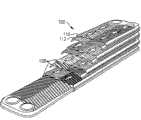
参考图1,图示出根据本发明的一个实施例的后混合饮料分配器50。从外侧看去,饮料分配器50包括具有铰接前门54的壳体52。壳体52还包括平台或滴盘56,用于放置接收器58,例如接收后混合产物的各种大小的杯子。分配按钮60a和60b可位于壳体52上的各种位置,以便操作者启动分配循环。在图1所示的具体实施例中,一组分配按钮60a或60b位于滴盘56的每一侧上以控制来自每一分配喷嘴(未示出)的产物的分配。使分配按钮处在除了前门54之外的位置,使得更易于接线,而且在前门54打开的时候,按钮也仍旧是操作者可看见的和可用到的。Referring to FIG. 1 , a
如图示的示例所示,分配按钮60a和60b可包括对应于各种份量大小的按钮,例如:小、中、大和超大。按钮也可包括这样的按钮:允许操作者取消/中断已经起动的分配循环、或者在按钮被按压(“结束”或“暂时开动”)时手工地分配。所述按钮也可包括指示机器的状态的灯。分配按钮60a和60b可以有背光照明以增强可见性,并且可以是在分配器上提供更多信息的较大显示器(或界面)的一部分。As shown in the illustrated example, dispensing
仍然参考图1,示出了显示器62,例如液晶显示器,其位于滴盘56的下面且在分配器壳体52上,用于显示与机器有关的信息。这种信息可包括错误信息、状态、诊断信息、操作指令等。类似于分配按钮,使显示器62远离前门54在接线和功能性的方面是有利的。分配器壳体52的其它零件可包括带有狭缝66的金属面板64,所述狭缝66用于制冷系统所需的进气。Still referring to FIG. 1 , there is shown a
现在参考图2,分配器50的剖视图显示出其各个内部零件。在壳体52的内部且在前门54之后的是浓缩物箱室68(或隔箱),用于放置浓缩物的预包装的供给物,且用于在分配前使浓缩物与稀释剂混合。在一个实施例中,箱室68设置有至少一个,优选两个浓缩物保持器70,所述保持器70中的一个示于附图。浓缩物(或添加剂、溶质)的预包装供给物(未示出)存储在浓缩物保持器70之内,且浓缩物供给物的排出管72装入到浓缩物运送系统74中,所述运送系统74继而将浓缩物运送到混合分配系统76。稀释剂(或溶剂),通常为可饮用的液体,例如饮用水、碳酸或无碳酸的,通过单独的运送系统(例如供水系统78)供给到混合分配系统76中。后混合产物最后通过混合喷嘴80分配到接收器58中。Referring now to FIG. 2, a cross-sectional view of
仍然参考图2,饮料分配器50也包括制冷系统82,制冷系统82提供必要的制冷以冷却浓缩物箱室68和供给通过供水系统78的水。在一个实施例中,提供控制系统54以监控、调节和控制分配器50内的各种系统的操作,例如制冷系统82、浓缩物运送系统74、供水系统78和混合分配系统76。控制系统84也可为维修技师或操作者提供错误诊断。Still referring to FIG. 2 , the
电源开关85位于分配器壳体52上,具体地,位于图示实施例的滴盘56的外部。在分配器壳体52的背面的插销86将需要电力的系统连接到外部电源。例如,供水系统78和/或制冷系统82的各种零件被包在绝缘材料88中。A
在优选的实施例中,一个饮料分配器50包含至少两条生产线,这样使得上文关于图2所述的大部分零件在同一分配器壳体52中被并排复制。例如,两组浓缩物保持器70、浓缩物运送系统74、供水系统78的部分、混合分配系统76可制造安装到一个分配器50中。制冷系统82也在需要冷却两条生产线的地方分为两部分。由于两条生产线,操作者具有通过同一分配器提供两种不同后混合产物的选择。在一个实施例中,分配器50的占地面积或尺寸不大于约11英寸(约28.0cm)宽、约25英寸(63.5cm)深、以及约55英寸(88.9cm)高。为了节省空间,分配器50内的各种独立零件可设计为集成模块,以减小无关的连接或密封零件并且使其更易于维修。In a preferred embodiment, a
进一步通过以下非限制性的示例说明本发明的特征。The characteristics of the present invention are further illustrated by the following non-limiting examples.
制冷系统Cooling System
现在参考图3,图示出根据本发明的制冷系统82的实施例。在一个实施例中,制冷系统82包括一个或多个蒸发器、压缩机90、冷凝器92、风扇94、空气过滤器96、干燥器98、以及一个或多个任选的温度传感器、本领域技术人员已知的零件。在控制系统84的控制下,制冷系统82冷却浓缩物箱室68和供水系统78。在一个实施例中,控制系统84程序设计成:如果过滤器96未安装,则阻止制冷系统82的使用。这防止风扇94进入工作并且因此保护冷凝器92不受未过滤空气流的污染。邻近于为控制系统84提供反馈的过滤器96的簧片开关能够完成所述功能。此外,为了在需要时为供水系统78提供制冷,本发明在其制冷系统82中包括板式热交换器,例如硬焊板式热交换器(BPHX)100。Referring now to FIG. 3 , an embodiment of a
在图4中示出说明性的制冷剂回路,其中,制冷剂流过压缩机90、邻近风扇94的冷凝器92和各种阀门102,所述阀门102包括引导制冷剂的流动的电磁阀。所述回路包括主回路104和副回路106,所述主回路104冷却供水,所述副回路106冷却浓缩物箱室68。An illustrative refrigerant circuit is shown in FIG. 4 in which refrigerant flows through
在一个实施例中,主回路104使供水,例如流率为大约4盎司(约0.12升)每秒或约2加仑(约3.8升)每分钟的加压供水,降低至少5℉(2.8℃),或者优选约10℉(5.6℃)。并且副回路106将浓缩物箱室保持在40℉或低于40℉(2.8℃)。在一个特征中,为了保证供水的几乎即时的冷却,主回路104和副回路106从不同时启动:只有一个回路在任何给定时刻启动。而且供水主回路104始终具有高于箱体副回路106的优先级。在另一个特征中,来自饮料塔或水增压器/冷却器系统的水被引导流入和流出BPHX 100以达到热交换器中的最大效率。In one embodiment, the
现在参考图5,其中,以分解剖视图示出BPHX 100。BPHX 100包括多个填密、焊接或硬焊在一起的波纹状的薄不锈钢板108层。这种BPHX例如可从Alfa Laval有限公司购买。在一个实施例中,BPHX 100用铜或镍材料来硬焊,并且称作铜硬焊板式热交换器。在另一个实施例中,BPHX 100是不锈钢硬焊板式热交换器。当形成在一个板上的水管道110位于形成在相邻板中的制冷剂管道112的附近时,波纹状的BPHX板108提供最大量的热交换表面。Reference is now made to FIG. 5, wherein the
制冷剂和水都受螺线管控制,使得水只在制冷剂流动的时候流过BPHX 100,并且反之亦然;产生立即的更节能的热交换。在一个实施例中,水和制冷剂以同向流动的形式流动,这意味着它们都从交换器的一侧(顶部或底部)流向另一侧。在优选的实施例中,水和制冷剂以反向流动的形式流动,其中,热水从交换器的顶部流入,而冷的制冷剂从交换器的底部流入。结果,当水被冷却时,其在前进通过交换器的时候经过甚至更冷的制冷剂,促使水温的快速降低。结果,本发明的制冷系统能够在需要时冷却水流而不使用冷库,例如储冰桶。换句话说,制冷系统在无冰环境中运转。Both the refrigerant and the water are solenoid controlled so that the water only flows through the
为了防止水回路的意外冻结,分配器的控制系统程序设计为在足够量的水已经进入回路之前阻止制冷系统的致动。例如,如果BPHX保持12盎司(约0.35L)的水,并且在测量水流的位置确定需要至少21盎司(约0.62L)的水以确保BPHX内的水管道被充满,那么,控制系统将程序设计成在为制冷系统的水冷却主回路通电之前发出指令控制21盎司(约0.62L)的水已经在每个动力循环中流过转子流量计。To prevent accidental freezing of the water circuit, the dispenser's control system is programmed to prevent activation of the refrigeration system until a sufficient amount of water has entered the circuit. For example, if the BPHX holds 12 ounces (about 0.35 L) of water, and at the location where the water flow is measured, it is determined that at least 21 ounces (about 0.62 L) of water are required to ensure that the water lines in the BPHX are filled, then the control system will program the Before energizing the water cooling main circuit of the refrigeration system, a command control 21 ounces (about 0.62 L) of water has flowed through the rotameter in each power cycle.
返回参考图4,制冷系统82的箱室副回路106可利用传统制冷技术中的任一种(例如,冷壁技术)以冷却浓缩物箱室68。因为分配器存储并制造用于消费的产物,重要的是将浓缩物箱室68维持在充分抑制潜在的有害细菌的生长的温度,例如等于或低于40℉(4.4℃)。在一个实施例中,箱室副回路106利用毛细管制冷控制方案,因为系统的负载相当恒定。Referring back to FIG. 4 , the compartment
稀释剂运送系统diluent delivery system
参考图6,示出供水系统78的实施例。在分配器的背面,饮用水在进口114被引入到供水系统78中。进口114适于允许0.5英寸(1.27cm)NPT(美制管螺纹)的进口连接到外部供水源,例如店内的水冷却器/增压器系统。引入的水可以增压到例如约20-100psi(磅每平方英寸),并且预冷却到大约45℉(约7.2℃)。在一个实施例中,供水系统78提供加压水流作为“主从”混合系统中的主物质。这种系统根据主物质(在本例中是水)的送出速率调节从物质(在本例中是浓缩物)的送出速率,因此,只主动地为两种成分中的一种调节速率。通过制冷系统82的加强作用,供水系统78也可进一步提供引入的水的冷却,例如对40℉(约4.4℃)冷却额外的5℉(约2.8℃)。基于上述原因,包括水管道116a和116b的供水系统78的部分或全部是隔热的。Referring to FIG. 6 , an embodiment of a
仍然参考图6,供水系统78延伸为水管道116a经过任选的压力调节器118。压力调节器118可将水流调整到所需的压力和流率,例如,小于或等于约30psi以及约2加仑(约3.8L)每分钟。压力调整后的水然后供给到制冷系统82的部分中,具体而言是BPHX 100。进一步冷却的水离开BPHX 100,进入到管道116b中。因为图示的实施例具有来自两个浓缩物供给源的两条生产线,在这里,水在进入相应的混合分配系统76a和76b之前分为两部分并且流到两个流量计组件120a和120b中,且最后分配为最终产物的一部分。Still referring to FIG. 6 , the
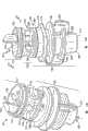
现在参考图7,流量计组件120设计成使无关零件、连接器和夹具最小化,同时将流动控制和监控的功能组合到一个组件中。在一个实施例中,流量计组件120在一体化壳体123之内包括歧管122,所述一体化壳体123具有第一臂124和第二臂126。第一臂124为流体输入提供至少一个进口128,第二臂126为流体输出提供至少一个出口130。进口128与出口130通过通孔(未示出)流体连通。第二臂126的取向确定流体输出的方向。在一个实施例中,沿着相对于第一臂124的轴线约45-60度的轴线构造第二臂126。Referring now to FIG. 7, the
仍然参考图7,在进口128的下游和出口130的上游,流量计或转子流量计(未示出)嵌入或集成在歧管壳体123的第一臂124中。流量计通过产生表示流体流率的模拟输出信号来响应任何流体流。邻近第一臂124上的流量计的是适配器132,适配器132的构造和大小适于流量计传感器134安装在其凹槽中。流量计传感器134感测流量计产生的输出信号并通过接线136传送到控制系统。控制系统使用这个信息来设定浓缩物泵的步速以获得理想的浓缩物比例,如随后段落所述。为了确保精确的读数,在流量计的上游,任选的压力补偿流动控制阀(未示出)可并入在第一歧管臂124中以调节流到流量计中的水流。压力补偿流动控制阀优选是单向阀。另外,另一个单向阀,例如止回阀(未示出),可任选地嵌入在第二壳体臂126中以防止任何朝向流量计的实质性回流。来自混合系统的逆流可污染流量计并阻碍其正确的功能。Still referring to FIG. 7 , a flow meter or rotameter (not shown) is embedded or integrated in the
仍然参考图7,为了最小化供水系统中的连接零件的量,流量计组件120的端口装备有装配件,所述装配件允许组件密封地接收上游管道和下游管道,所述管道优选具有标准大小,例如直径为0.5英寸(1.27cm)。具体地,进口128和出口130分别配备有连接器组件138和140。Still referring to FIG. 7 , in order to minimize the amount of connecting parts in the water supply system, the ports of the
流量计组件120还包括闸门保持阀,例如电磁阀142,其密封地固定到歧管壳体123并位于流量计的下游和出口130的上游。电磁阀142能够切断并重新打开水流,且需要控制从BPHX到混合系统的水流。在图示的实施例中,电磁阀142被预先制造,然后通过螺钉144固定到歧管壳体123上。The
现在参考图8,以分解视图示出流量计组件120的更详细的细节。为了制造组件120,在一种方法中,提供全部可购买到的压力补偿流动控制阀145、带有涡轮148的流量计146、和止回阀150。然后,可以制造歧管壳体123,例如通过使用国家科学基金会(NSF)列出的食品级热塑性塑料来注塑成型,同时在其中组装沿着歧管的通孔按流体流下的顺序布置的压力补偿流动控制阀145、流量计146和止回阀150。对于在此图示的具体的歧管构造,端口插头152用于密封住壳体123上的储备口153。可购买到的电磁阀142然后通过双向螺栓螺钉144和顶部螺母154固定到歧管壳体123。Referring now to FIG. 8 , greater detail of the
仍然参考图8,在制造歧管壳体123后,连接器组件138和140可分别装备到入口128和出口130。在一个实施例中,连接器组件是速卸式接头,并且可包括可扩展构件,所述可扩展构件构造成安装在端口的内部以密封地接收连接管道。如在此所示,连接器组件138和140中的每一个可包括倒钩式可扩展构件156,其带有外部O形环158以用于密封。在一个实施例中,可扩展构件156包括多个延伸部,所述多个延伸部围成一圈布置并且被狭缝分开。例如,从俄亥俄州Ravenna的派克汉尼汾有限公司(Parker Hannifin Corporation of Ravenna,Ohio)可购得商标为TrueSeal的这种连接器组件。此外,流量计传感器134可通过歧管壳体123上的适配器结构132固定到流量计组件120。Still referring to FIG. 8 , after fabrication of
通过将多个部件集成到一个以歧管为基底的组件中,例如压力补偿流动控制阀、流量计(和/或其传感器适配器)、电磁阀和止回阀,本发明经济地使所有这些零件结合到一个只有两个开口的容易维修的组件中。此外,设计所述组件使得这些有限数量的开口可装备连接器,所述连接器可通过简单的轴向运动而不需任何工具的帮助密封地连接到其它管道,进一步增强可维修性。集成组件也使得更易于制造围绕所述集成组件的紧密模制的隔热包套或外套。By integrating multiple components into one manifold-based assembly, such as pressure-compensated flow control valves, flow meters (and/or their sensor adapters), solenoid valves, and check valves, the present invention economically makes all these parts Combined into an easily serviceable assembly with only two openings. Furthermore, the assembly is designed such that these limited number of openings can be equipped with connectors that can be sealingly connected to other pipes by simple axial movement without the aid of any tools, further enhancing serviceability. The integral assembly also makes it easier to manufacture a tightly molded insulation wrap or jacket around the integral assembly.
浓缩物运送系统Concentrate Delivery System
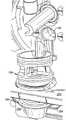
参考图9,在本发明的一个实施例中,浓缩物运送系统74将来自储蓄器的浓缩物运送到混合分配系统76,在所述混合分配系统76中,所述浓缩物与稀释剂(例如饮用水)汇合,并且这两者在分配前混合在一起。图9示出去除前门的图1和2的分配器实施例50,并且以局部分解图绘制两条生产线中的一条。Referring to FIG. 9, in one embodiment of the present invention, a concentrate delivery system 74 delivers concentrate from a reservoir to a mixing and dispensing
浓缩物以包装的形式装载到浓缩物箱室68中,所述浓缩物可以是液体或半液体、且可以包含固体组分,例如具有或没有果肉、冰凌等的果汁或浆液浓缩物。所述包装可以是柔软的半刚性或刚性容器。可以提供浓缩物保持器70以容纳所述浓缩物包装。在一个实施例中,浓缩物保持器70是带有铰接盖的刚性盒体,所述铰接盖打开以露出与保持器壳体分离或构成一体的斜坡162,以辅助浓缩物从其包装排出。斜坡162可以是平面的或曲线的,以更好的容纳所述包装。浓缩物保持器70也可在其壳体(例如盖罩160及其相对的侧面168)上具有相应的凸脊164和凹槽166,以辅助堆叠和稳定的平行放置。浓缩物保持器70也可具有手指把手或手柄,所述手指把手或手柄易于操作者从浓缩物箱室68的前面抓握以有助于保持器的移除。例如,保持器70的边缘附近的垂直凹槽165可起到所述功能。Concentrate, which may be liquid or semi-liquid and may contain solid components, such as fruit juice or syrup concentrate with or without pulp, ice, etc., is loaded into the
参考图9和10,浓缩物包装随排出管72运动,所述排出管在浓缩物保持器70的底部安置在开口170中。浓缩物保持器70可包括突出部或类似结构以便于排出管72在开口170中锁定在优选的位置,以防止阻碍泵操作的弯折或失准。此外,这种锁定位置可确保传感器的正确功能,所述传感器监控排出管内的液体流。排出管72伸出浓缩物保持器70并且连接到泵压头172的顶部上的管适配器171。在管适配器171下面的是细长的圆筒形活塞壳体176,在所述活塞壳体176中,由电机181驱动的旋转轴(未示出)致动的活塞177运动以将浓缩物从管适配器171传送到混合壳体178。在混合壳体178之内的是混合喷嘴80的部分,所述混合喷嘴80的顶部表面182与混合壳体178的顶部内表面形成混合室184。水也被运送到进行混合的混合室184中。然后通过混合喷嘴80的排放出口186分配重组的产物。Referring to FIGS. 9 and 10 , the concentrate package moves with the
仍然参考图9和10,泵压头172通过锁定环190安装到适配器板188上。在一个实施例中,锁定环190具有反馈结构,所述反馈结构确保锁定环190处在正确的锁定位置。结果,分配器机器50不会通电,除非泵压头172和锁定环190被正确地装配。这种反馈结构的示例是磁体192,所述磁体192启动簧片开关194(图10),所述簧片开关在适配器板188的后面安置在对应于磁体192的正确锁定位置的位置。Still referring to FIGS. 9 and 10 , pump head 172 is mounted to
现在参考图11,在更详细的视图中,示出活塞177伸出适配器板188的上开口196。活塞177具有U形凹陷部180(在图12中较好地示出),其在运转期间临时保持浓缩物。仍然参考图11,在活塞177从排出管72朝喷嘴顶部表面182传送浓缩物时,加压冷却水从适配器板188的下开口198压出以与浓缩物混合。然后混合后的产物流过喷嘴顶部表面182的开口202。Referring now to FIG. 11 , in a more detailed view, the
根据本发明的一个特征并且返回参考图10,活塞177例如是容积式泵的一部分,例如章动泵或无阀活塞泵,例如从华盛顿温哥华的Miropump公司购得的泵。章动被定义为任何旋转体的轴线的摆动。在2004年9月30日申请的名称为“容积式泵”的共有的美国申请序号第10/955,175号中详细描述了容积式泵,该文件的全部公开内容在此以参见的方式引入在任何适用的地方。所记载的章动泵是直接驱动的容积式泵,用于使液体从起始点(在本例中是管适配器171)运动至目的地(这里是混合室184)。活塞177构造成围绕其轴线旋转,使得所述活塞的U形凹陷部180向上面向管适配器171以装载浓缩物,并且在一个循环的结尾向下面向混合室184以卸载其内含物。同时,活塞171也沿箭头204指示的方向往复摆动,提供附加的正向力以传送浓缩物。According to a feature of the invention and referring back to FIG. 10 ,
与螺杆泵或蠕动泵相反,利用容积式泵,例如章动泵或无阀活塞泵的一个优点是对磨损或浓缩物粘度变化的增强的抗扰性。现有技术的泵经常遭受由于机器磨损或中断周期的需要而引起的运送中的不一致性;这些泵也面对低粘度的限制的问题,因为较高粘度的浓缩物要求这些泵的更大的功率。相反,容积式泵能以一致性且不需要速度调整的方式运送很宽范围的粘度的浓缩物负载。因此,为了运送预定量的浓缩物,只需要设定泵速一次。One advantage of using positive displacement pumps, such as nutating pumps or valveless piston pumps, as opposed to screw pumps or peristaltic pumps, is increased immunity to wear or changes in concentrate viscosity. Prior art pumps often suffer from inconsistencies in delivery due to machine wear or the need to interrupt cycles; these pumps also face low viscosity limitations as higher viscosity concentrates require greater power. In contrast, positive displacement pumps are capable of delivering concentrate loads over a wide range of viscosities in a consistent manner and without the need for speed adjustments. Thus, the pump speed only needs to be set once in order to deliver a predetermined amount of concentrate.
在一个实施例中,泵配备有编码器以监控活塞的转数,例如,每转可等于1/32(约0.0009L)盎司的浓缩物。编码器可安置在泵电动机的旋转轴上以对活塞已经相对于水流转动的转数进行计数。控制系统根据两条信息决定泵的转数:预定的、所需的浓缩物和水之间的混合比,以及上述流量计组件感测到的水流量。In one embodiment, the pump is equipped with an encoder to monitor the number of revolutions of the piston, for example, each revolution may equal 1/32 (approximately 0.0009 L) ounce of concentrate. An encoder may be placed on the rotational shaft of the pump motor to count the number of revolutions the piston has turned relative to the flow of water. The control system determines the number of revolutions of the pump based on two pieces of information: the predetermined, desired mix ratio between concentrate and water, and the water flow sensed by the aforementioned flow meter assembly.
仍然参考图10,任选地,控制系统可程序设计成确保泵活塞177在每一次分配操作的结尾返回到吸入位置。通过使位于吸入冲程的活塞的U形凹陷部面向上方,混合室184对浓缩物的入口点将被完全密封以防止浓缩物的任何泄漏。这也允许水在每次分配循环期间和之后冲洗并清理泵的出口以及混合室184,所述水在供水系统78的端口76进入混合室184。Still referring to FIG. 10, optionally, the control system can be programmed to ensure that the
混合分配系统Hybrid Dispensing System
混合分配系统76提供公共空间,以用于浓缩物和稀释剂汇合和混合。混合分配系统76也包括促进混合的部分。返回参考图9,在一个实施例中,混合分配系统76包括混合壳体178和混合喷嘴80。如前所述,混合喷嘴80的顶部装到混合壳体178中,并且在其间形成混合室184(图10)。在一个实施例中,混合壳体178被制造为泵压头172的一部分。Mixing and dispensing
现在参考图11,根据本发明的一个特征,喷嘴顶部表面182上的障碍结构或分流器200面向引入的稀释剂流,并且压迫稀释剂以喷射到由活塞177卸载而引入的浓缩物流中。在稀释剂是水的示例中,引入的水流通过下板开口198进入混合室,然后进入混合室壳体178(图10)的进水口206(图10)。由改向的水流产生的湍流延续通过整个分配循环,并且有效地产生浓缩物和水的均匀且充分混合的混合物。Referring now to FIG. 11 , according to one feature of the present invention, an obstruction or
所述混合物然后流过喷嘴顶部表面182的开口202,并在脱出排放出口186(图9)之前经过混合喷嘴80的其余部分。在一个实施例中,在为“结束”操作分配所需的产物之后,浓缩物和水的混合物保持在混合室中。The mixture then flows through
图13A、13B和13C绘制了根据本发明的混合喷嘴80的一个实施例。喷嘴体189具有进口段191、出口段195和两者之间的降压段193。喷嘴体189沿着旋转轴197延伸,并且限定从进口段191到出口段195的液体通路199。进口段191包括喷嘴顶部261和所述喷嘴顶部261上的障碍结构或分流器200。降压段193包括位于喷嘴顶部261和腔室底板264之间的降压室263。减压室263可被多个壁266部分地分割成多个腔室。在每个腔室中,在底板周边附近的腔室底板264上有细长的扩散缝。可以有任意数量的扩散缝,例如四个,在附图中绘出所述扩散缝中的标记为268a和268b的两个扩散缝。与进入开口202相比,这些扩散缝268更远离喷嘴轴线197以朝喷嘴周边引导液体流。Figures 13A, 13B and 13C depict one embodiment of a mixing
仍然参考图13A-13C,扩散缝268通向由喷嘴进口段195限定的漏斗270(在图13C中最佳示出)。在此使用的漏斗指的是限定通道的结构,在所述通道中,一端的横截面大于另一端的横截面;漏斗的直径可连续地朝一端逐渐递减,或者所述逐渐递减被直径不变的区段中断。在图示的实施例中,漏斗270包括内壁272,从顶部到底部,所述内壁272首先具有恒定的直径,然后朝排放出口186的边缘274连续地逐渐递减。Still referring to FIGS. 13A-13C , the
具体参考图13C,喷嘴的液体通路199起始于喷嘴顶部表面182的进入开口202。在喷嘴体189部分地插在混合壳体中时,喷嘴顶部表面182用作混合室的底板。虽然喷嘴顶部表面182可以是扁平的,但在优选的实施例中,其在底板的最低点的进入开口202旁边略微地弯曲,以助于重力排出。喷嘴通路199的初始部分是具有恒定直径的进口通道262,所述进口通道262从进入开口202延伸通过喷嘴顶部261并进入到降压室263中。在一个实施例中,相比于喷嘴顶部表面182的大小,进入开口202设计成受到相当地限制,因此在后混合产物流过进入通道262并进入降压室263时,流体通路199的平均横截面面积的显著增大极大地减小液体流的压力以及动量。由降压室263引起的压降用于在分配产物时减少喷溅。在一个实施例中,降压室263的横截面面积比进入通道262的横截面面积大至少20倍,优选50倍,更优选100倍。在一个实施例中,进入开口202具有0.125英寸(约3.2mm)的直径,且降压室263具有1.375英寸(约3.5cm)的直径,因此在横截面面积上有121倍的增大。Referring specifically to FIG. 13C , the nozzle's
喷嘴顶部261和腔室底板264都具有环绕其周边的凹槽,所述凹槽各自容纳O形环276a/276b。在喷嘴体189被锁入时,O形环密封混合壳体的内部。Both the
仍然参考图13C,喷嘴通路199的尾部包括漏斗270。通向漏斗的扩散缝268可以具有各种形状,包括椭圆形、芸豆形、圆形、矩形、扇形、弧形等。扩散缝268沿着腔室底板264定位以朝内漏斗壁272引导产物流。与通路199的中间自由下落相反,在产物沿漏斗壁272流下时,喷溅被进一步减少。流动路径在从扩散缝268进入到漏斗270时的横截面面积的增大也倾向于减缓流动。漏斗270的形状在其很大部分朝底部边缘274连续地逐渐变小时,也倾向于在流动朝喷嘴轴线197回到中心位置时产生螺旋流型。居中的产物流使得更易于在等待的接收器中接收全部的产物。Still referring to FIG. 13C , the tail of the
喷嘴体189的区段以及在此描述的其它不同的结构可在使用前单独地制造和装配,或者,制造成为一个一体件。喷嘴体189应当按大小成形以使至少进口段191和降压段193装到喷嘴壳体中,例如混合壳体178(图10)。喷嘴可以用各种食品安全材料制成,包括不锈钢、陶瓷和塑料。The segments of the
返回参考图13A、13B和13C,分流器200提供升高的阻挡面201,所述阻挡面201改变引入的水流的方向。分流器200绘制成基本上圆筒形,但是本领域技术人员理解,所述分流器200可以具有各种几何形状中的任一种。阻挡面201设计成使水和浓缩物之间的接触最大化。在此情况下,阻挡面201改变加压水流的方向,使得水流与引入的浓缩物流迎面地汇合,即,这两股流以接近180度的角度、或者以钝角汇合。返回参考图11,阻挡面201在其改变水的方向时产生喷流型式,使得水分子沿各个方向跳出表面,如箭头203a和203b所示。引入的浓缩物流大致沿箭头205所示的重力下降的方向运动。两股流以角度207汇合。在一个实施例中,角度207大于90度,并且优选大于120度。Referring back to Figures 13A, 13B and 13C, the
阻挡面201可具有平坦或不平坦、均匀或分段的各种几何形状。例如,阻挡面201可以是凹入或凸起形、褶皱形、波纹形等。在图示的实施例中,阻挡面201是凹入面,以产生宽薄有力的喷流型的分流水,所述分流水切入到浓缩物流中并在混合腔室之内产生湍流型。这种湍流型导致均匀混合的产物,所述产物然后被压入到喷嘴顶部表面182上的开口202中。阻挡面201的边缘可以是尖锐的或钝的。在一个实施例中,为了避免对操作者的伤害,分流器200的顶部被磨平或倒圆。The blocking
为了确保阻挡面201基本上面对引入到混合室中的水流,即,在混合室内沿预定取向锁定喷嘴体189,某些锁定特征可添加到喷嘴上。参考图13B和13C,在一个实施例中,阻挡面201关于喷嘴轴线197非对称定位,因此,提供也关于喷嘴轴线197非对称的锁定结构以确定喷嘴的取向。在一个实施例中,这种锁定结构包括非对称套环,所述套环与喷嘴体189构成一体。具体地,非对称套环可以是D形套环278,其位于腔室底板和中间套环280之间并具有扁平侧面279。在D形套环278和中间套环280之间有锁定凹槽282,其与如下文所述的适配器板接合。D形套环278和中间套环280都优选与喷嘴体189的其余部分构成一体。To ensure that the blocking
仍然参考图13B和13C,另一锁定结构可以是一组沿喷嘴轴线197延伸的突出部。在一个实施例中,所述突出部是一对翼状手柄284和286,所述翼状手柄284和286沿喷嘴体189的外部占据不同的跨度。锁定手柄284刚好从下套环288的下方向上伸出并在齐平于中间套环280的顶部的高度终止。规则手柄286也刚好从下套环288的下方向上伸出,但是在中间套环280的顶部之下终止。Still referring to FIGS. 13B and 13C , another locking structure may be a set of protrusions extending along the
现在描述锁定结构的使用和混合喷嘴的安装。现在参考图14A和14B,在适配器面板290中有相应的锁定结构,其便于混合喷嘴的安装和锁定。在一个实施例中(图9),适配器面板290固定地位于前门之后,且在混合室184的下面:其相对于水路径的空间关系是固定且已知的。适配器面板290限定一个或多个开口292,所述开口292的大小和形状适于使非对称套环278穿过,但喷嘴体189的较大的中间套环280不能穿过(图13C)。如图14A提供的顶视图所示,在该特定实施例中,非对称套环278是D形,适配器开口292也是D形的。The use of the locking mechanism and installation of the mixing nozzle will now be described. Referring now to Figures 14A and 14B, there are corresponding locking features in the
参考图14B提供适配器面板290的底视图,D形开口292位于大部分圆形的凹部之内,使得所述凹部从面板290的其余部分降低,且D形开口292的棱缘被凹入底板294围绕。凹入边沿296的大小和形状适于紧贴地配合中间喷嘴套环280。除了配合中间喷嘴套环280的圆形部之外,所述凹部具有弧形的锁定槽298;锁定槽298设计成与锁定手柄284(图13C)配合地决定锁定和解锁顺序。具体地,锁定槽298按大小成形,以使锁定手柄284的顶部紧贴地装在锁定槽中且能够在锁定槽的一侧299和另一侧300之间往复旋转,使喷嘴体的其余部分随其一起旋转。14B provides a bottom view of the
在操作中,参考图13B和14B,喷嘴进口段191和喷嘴降压段193从适配器面板290的下方插过开口292。因为其非对称的形状,D形套环278的扁平侧面279必须与开口292的扁平侧面297对准。中间喷嘴套环280将不能穿过适配器开口292,但是会抵靠凹入底板294留在面板的凹入边沿296之内。在这一点上,喷嘴体189处在解锁位置,锁定手柄284抵靠锁定槽298的“解锁”侧面299。在图15中绘制出解锁位置,图15示出适配器面板290的凹入底板294接合在喷嘴D形套环278和喷嘴中间套环280中间的锁定凹槽282之内,且锁定手柄284朝向混合室184的正背面。In operation, referring to FIGS. 13B and 14B ,
返回参考图13B和14B,锁定槽298的取向决定锁定手柄284可仅仅逆时针旋转(注意图14B是取自底部的视图),直到锁定手柄284停在锁定槽298的“锁定”侧面300为止。在图16中绘制出锁定位置,在图16中,升高的阻挡面201直接面对从开口198的方向进入的水流。为了解锁喷嘴,只要通过顺时针转动手柄284和286直到其停在图15所示的解锁位置来颠倒上述的运动顺序。然后操作者可使用下喷嘴套环288作为抓握辅助件以从适配器面板290的开口292向下拉出喷嘴体189。13B and 14B, the orientation of the
控制系统Control System
为了监控和控制分配器内的各种系统的操作,提供控制系统。控制系统可包括在工业中已知用于执行各种计算和存储功能的微处理器、一个或多个印刷电路板和其它部件。在一个实施例中,控制系统维持并调节制冷系统、稀释剂运送系统、浓缩物运送系统和混合分配系统的功能。更具体地,控制系统涉及:In order to monitor and control the operation of the various systems within the dispenser, a control system is provided. The control system may include a microprocessor, one or more printed circuit boards, and other components known in the industry for performing various computing and storage functions. In one embodiment, the control system maintains and regulates the functions of the refrigeration system, diluent delivery system, concentrate delivery system, and mix distribution system. More specifically, the control system involves:
·制冷系统:监控过滤器的放置、启动水冷却回路、支持水冷却回路优于箱体冷却回路;Refrigeration system: monitor the placement of filters, start the water cooling circuit, support the water cooling circuit over the box cooling circuit;
·稀释剂运送系统:调节一个或多个在各种位置控制水流的闸门保持开关、调节水流的压力、接收并存储流率输出;Diluent delivery system: adjusts one or more gate hold switches that control water flow at various positions, regulates water flow pressure, receives and stores flow rate output;
·浓缩物运送系统:监控泵压头锁定、接收并存储有关包含所需的产物混合比的浓缩物的信息、确定浓缩物状态、计算并调节泵速和装填量、控制活塞位置;Concentrate delivery system: monitors pump head lock, receives and stores information on concentrate containing desired product mix ratio, determines concentrate status, calculates and adjusts pump speed and fill volume, controls piston position;
·混合分配系统:启动对系统的清理、分配正确的装填量;和Mix and dispense system: initiates purge of the system, dispenses the correct charge; and
·诊断:识别错误并提供校正指令。• Diagnostics: Identify errors and provide corrective instructions.
上述方案的意思是提供总体的指导并且不应当视为严格的描述,因为控制系统经常与大于一个的系统一起工作以执行特定的功能。在执行制冷相关的功能中,如前所述的控制系统确保:如果过滤器没有被正确安装,那么制冷系统就不通电。在此情况下,控制系统还可提供所要显示的诊断信息,所述诊断信息提醒操作者安装过滤器。控制系统还通过来自流量计的输出信号监控已经经过流量计的水量,并允许只在已经经过足够的水量,例如21盎司(约0.62L),以防止水管道的冻结之后,启动水冷却主回路。The above schemes are meant to provide general guidance and should not be viewed as strict descriptions, as control systems often work with more than one system to perform specific functions. In performing refrigeration-related functions, the control system as previously described ensures that the refrigeration system is not energized if the filter is not installed correctly. In this case, the control system can also provide diagnostic information to be displayed, which reminds the operator to install the filter. The control system also monitors the amount of water that has passed through the flowmeter through the output signal from the flowmeter, and allows the water cooling main circuit to be activated only after sufficient water has passed, such as 21 ounces (approximately 0.62L), to prevent freezing of the water pipes .
然而,一旦水冷却主回路已经启动,控制系统就会支持所述水冷却主回路优于箱体冷却副回路。控制系统也确保在任何给定时刻只有一个制冷回路被通电,而且在箱体高于预定温度时使箱体冷却回路通电。However, once the water cooling primary loop has been activated, the control system favors said water cooling primary loop over the cabinet cooling secondary loop. The control system also ensures that only one refrigeration circuit is energized at any given time, and energizes the case cooling circuit when the case is above a predetermined temperature.
稀释剂运送系统可在沿着水路线的各个位置包括闸门保持开关,例如电磁阀。控制系统控制这些开关的操作以调节水流,例如,进出水冷却回路,具体是在水进入和离开BPHX时。例如,控制系统也通过压力调节器调节水流的压力。来自流量计的输出信号被发送到控制系统以用于处理和存储。The diluent delivery system may include gate hold switches, such as solenoid valves, at various locations along the waterway. The control system controls the operation of these switches to regulate water flow, for example, into and out of the water cooling circuit, specifically as water enters and leaves the BPHX. For example, the control system also regulates the pressure of the water flow through a pressure regulator. The output signal from the flow meter is sent to the control system for processing and storage.
在每个分配循环中,一旦份量大小被请求,控制系统就通过读取来自流量计的水流的读数并增加从浓缩物泵分配的量以确定何时完成请求。所述份量中的每一种能够通过体积教导程序来校准。为加冰而补偿份量体积的条件可并入到控制方案中。In each dispense cycle, once a portion size is requested, the control system determines when the request is complete by reading the water flow from the flow meter and incrementing the amount dispensed from the concentrate pump. Each of the serving sizes can be calibrated through a volume teach program. Conditions to compensate for serving volume for ice addition can be incorporated into the control scheme.
关于浓缩物运送系统,控制系统确保:如果泵压头没有如前所述通过锁定环正确地装配,那么分配系统就不起动。按照主从方案执行的控制系统根据计算出的装填量和检测到的水流率调节泵速,从而获得所需的混合比,在所述主从方案中,水是主物质,浓缩物是从物质。不像浓缩物流和稀释剂流都被主动调节的现有技术控制机构中的一些机构,本发明的控制方案只主动地调整一个参数(泵速),使得系统更加可靠,更易于维修,且更不易于出故障。在每个分配循环的结尾,控制系统确保浓缩物泵的位置返回到吸入位置,使得在浓缩物运送系统和混合分配系统之间有效地形成密封。With regard to the concentrate delivery system, the control system ensures that the dispensing system does not start if the pump head is not fitted correctly with the locking ring as previously described. The control system implements a master-slave scheme in which water is the master substance and concentrate is the slave substance, by adjusting the pump speed according to the calculated fill volume and the detected water flow rate to obtain the desired mixing ratio . Unlike some of the prior art control mechanisms in which both concentrate and diluent flows are actively adjusted, the control scheme of the present invention actively adjusts only one parameter (pump speed), making the system more reliable, easier to maintain, and more efficient. Not prone to failure. At the end of each dispensing cycle, the control system ensures that the position of the concentrate pump is returned to the suction position so that a seal is effectively formed between the concentrate delivery system and the mixing and dispensing system.
现在参考图17,为了在浓缩物装载到分配系统中时给控制系统提供有关浓缩物的包装的信息,本发明提供数据输入系统。系统包括安装在分配器50中的标签208a或208b和标签读出器210。标签读出器210可以是光扫描器,例如激光扫描器或发光二极管(LED)扫描器。在一个实施例中,标签读出器210是可从Intermec Technologies公司购买的Intermec
现在参考图18,在标签的示例中,以条形码的形式显示数据,所述条形码对应于在此图形显示的参数。具体地,第一数据组214代表包装日期“2000年1月7日”,第二数据组216代表“时-分-秒”格式的包装时间(图示的实施例使用五位数的随机整数)。第三数据组218代表后混合产物中的稀释剂和浓缩物之间的所需成分比的标记,在此具体示例中是5∶1。第四数据组220代表包装的有效期“2000年1月26日”。第五数据组222代表冰的状态,即,所述冰是否是一般添加到由该浓缩物得到的后混合产物的冰。第六数据组224代表浓缩物的味道标识,在本例中,“A”代表橙汁。控制系统程序设计为根据预设公式将每个数据组译成实际信息。Referring now to FIG. 18, in the example of a label, data is displayed in the form of barcodes corresponding to the parameters shown graphically here. Specifically, the
一旦读出器210从标签208a或208b获得包装特有的信息,读出器210就向控制系统发送所述信息。然后控制系统就能够为使用者显示这种信息:调节产物的混合和分配、监测剩余浓缩物的量、以及监控浓缩物的新鲜度以确保安全消费。Once the reader 210 obtains the package-specific information from the tag 208a or 208b, the reader 210 sends the information to the control system. The control system can then display this information to the user: adjust product mixing and dispensing, monitor the amount of concentrate remaining, and monitor the freshness of the concentrate to ensure safe consumption.
现在参考图19,图示出与数据输入系统有关的操作步骤。在步骤226,从浓缩物箱室移除带有空的或过期浓缩物包装的浓缩物保持器。然后在步骤228,确定分配器的哪一侧是移除保持器的一侧或清空的一侧。为关于清空/输出状态的控制器设定内部标志。这可通过各种方式完成。例如,机器可具有监控浓缩物保持器的位置的传感器,或者可手工地教导机器哪一侧是移除浓缩物的一侧。在一个实施例中,在浓缩物保持器中(例如底部)嵌入磁体,使得移除保持器就触发处在分配器之内的相应位置的簧片开关,从而向控制系统发送移除信号。Referring now to FIG. 19, there is illustrated the operational steps associated with data entry into the system. At step 226, the concentrate holder with the empty or expired concentrate package is removed from the concentrate compartment. Then at
仍然参考图19,一旦控制器得知浓缩物保持器已经从分配器移除,在步骤230,控制器致动标签读出器,例如光扫描器,并且在步骤232,为产生作用的一侧开启指示器,例如红色和黄褐色LED。在步骤234,操作者用新的浓缩物包装再装满保持器,并且把保持器放回到分配器中。在步骤236,操作者手工地在新排出管上为启动的扫描器提供新标签并扫描条形码。或者,由分配器中的传感器或读出器自动地检测并读出标签。在步骤238,控制器确定扫描是否成功。如果不成功,控制器就在步骤240中指导操作者重新扫描条形码。然而,如果扫描是成功的,扫描器就会断电,且在步骤242中由控制器产生独特的产物标识符。这个每一浓缩物包装特有的独特标识符被保持在控制器上的记录表中作为永久记录以防止产物混合。Still referring to FIG. 19, once the controller learns that the concentrate holder has been removed from the dispenser, at
因为控制系统调节泵速,并且泵通过每次循环运送设定量的浓缩物,控制系统可在任何给定时刻监控从特定包装分配的浓缩物的量,并且为独特的标识符分派信息。因此,控制系统可计算并显示给定包装中剩余的理论量,或者警告操作者浓缩物在何时短缺。一旦包装被倒空,控制器就用无效状态标记相关的标识符,并且不允许重新安装该包装。控制系统也将使用所述独特的产物标识符以监测与其相关的包装已经被安装过多少次,并且在整个包装的寿命期间连续地监控浓缩物的用量。如果包装在完全使用之前从分配器移除,那么控制器将在同一包装重新安装在分配器中的时候识别出所述包装,并从上次记录的水平开始对容量倒计数。Because the control system regulates the pump speed, and the pump delivers a set amount of concentrate through each cycle, the control system can monitor the amount of concentrate dispensed from a particular package at any given moment and assign the information to a unique identifier. Thus, the control system can calculate and display the theoretical amount remaining in a given package, or warn the operator when there is a shortage of concentrate. Once the pack is emptied, the controller marks the associated identifier with an invalid status and does not allow reinstallation of the pack. The control system will also use the unique product identifier to monitor how many times the package associated with it has been installed and to continuously monitor the amount of concentrate used throughout the life of the package. If a package is removed from the dispenser before it is fully used, the controller will recognize the same package when it is reinstalled in the dispenser and will count down the capacity from the last recorded level.
再参考图19,独特标识符用于监控和调节浓缩物用量的其它方面。例如,在步骤244,控制器确定浓缩物是否已经过期或超过最佳使用日期。在步骤246,如果响应是肯定的,控制器就标记所述产物标识符并且不允许从当前包装的任何进一步的分配。在步骤248,例如通过两个红色LED显示警告信号。控制器也重新启动扫描器,且程序恢复到步骤234以开始替换包装。然而,如果在步骤244确定浓缩物尚未过期,控制器就在步骤250继续确定条形码是否仍然有效。如果响应是否定的,就启动步骤248和随后的步骤。如果响应是肯定的,启动步骤252,在这里,处理有关所需成分比的设定和先前由扫描包装标签获得的信息。在步骤254,控制器还从有关标签的扫描信息确定后混合产物中是否正常需要冰。Referring again to FIG. 19, the unique identifier is used to monitor and regulate other aspects of concentrate usage. For example, at
根据在步骤252和254中采集的信息,控制器计算操作者要求的每一份量大小所需的浓缩物的量。在步骤256,在显示后混合产物不需要冰的时候,默认的装载量用于所有的份量大小。否则,在步骤258,如果显示需要冰,那么通过预定值来偏置装填量。在任一情况中,控制器进行到步骤260,用也在步骤236中从标签的扫描获得的正确的味道标识更新分配器显示器。Based on the information collected in
根据本发明的一个特征,控制系统程序设计并配置成调节混合及分配过程以实现成分比的一致性,例如稀释剂和浓缩物之间大约10∶1到大约2∶1之间的成分比。控制系统需要两条信息来完成这一任务:所需的成分比和稀释剂的流率。如前所述,通过数据输入系统可获得所需的成分比,在所述数据输入系统中,标签为控制器提供信息。所述稀释剂的流率被接收作为计量装置、例如流量计产生的输出信号,所述计量装置与控制回路电气通信。除了设定浓缩物运送的速率,控制系统还根据份量大小信息(即要求的特定的份量大小)以及在后混合产物中是否需要冰(这个最后信息也优选来自包装标签)来决定分配周期的持续时间。According to one feature of the invention, the control system is programmed and configured to regulate the mixing and dispensing process to achieve a consistent ratio of ingredients, for example a ratio of ingredients between about 10:1 to about 2:1 between diluent and concentrate. The control system needs two pieces of information to accomplish this task: the desired composition ratio and the flow rate of the diluent. As previously mentioned, the desired ingredient ratios are obtained through a data entry system where the tags provide information to the controller. The flow rate of the diluent is received as an output signal generated by a metering device, such as a flow meter, which is in electrical communication with a control loop. In addition to setting the rate at which the concentrate is delivered, the control system also determines the duration of the dispensing cycle based on the portion size information (i.e. the specific portion size required) and whether ice is required in the post-mix product (this last information is also preferably from the package label) time.
在容积式泵(例如章动泵)用于抽吸浓缩物与稀释剂接触从而形成混合物的实施例中,电动机构造成致动章动泵,且每次电动机旋转所传送的浓缩物的量是固定的。因此,编码器可构造成调节电动机的转速以及浓缩物的传送率。与编码器电气通信的控制系统一旦已经计算出给定分配周期所需的转速和/或持续时间,其就向编码器发送指令。因此,适当的浓缩物的数量/体积被添加到每一分配周期。In embodiments where a positive displacement pump, such as a nutating pump, is used to draw the concentrate into contact with the diluent to form a mixture, the motor is configured to actuate the nutating pump and the amount of concentrate delivered per motor revolution is stable. Accordingly, the encoder may be configured to adjust the rotational speed of the motor as well as the delivery rate of the concentrate. Once the control system in electrical communication with the encoder has calculated the required rotational speed and/or duration for a given dispense cycle, it sends instructions to the encoder. Thus, the appropriate amount/volume of concentrate is added to each dispense cycle.
例如,控制器从包装标签接收10∶1的水和浓缩物之间的所需成分比。此外,流量计向控制器发送信号:水以大约4盎司(约0.12L)每秒的速率流动。这意味着浓缩物需要以大约0.4盎司(约0.012L)每秒的速率被抽吸。由于泵活塞的每次旋转始终运送1/32盎司(约0.0009L)的浓缩物,控制器设定活塞以12.8转每秒运转。如果对分配周期要求21盎司(约0.62L)的份量且根据包装标签在产物中不需要冰,控制器就确定所述分配周期应当持续大约4.8秒。For example, the controller receives a desired ingredient ratio between water and concentrate of 10:1 from the package label. Additionally, the flow meter sends a signal to the controller that water is flowing at a rate of approximately 4 ounces (approximately 0.12 L) per second. This means that the concentrate needs to be drawn at a rate of about 0.4 ounces (about 0.012 L) per second. Since each rotation of the pump piston consistently delivers 1/32 ounce (approximately 0.0009 L) of concentrate, the controller sets the piston to run at 12.8 revolutions per second. If a 21 ounce (approximately 0.62 L) portion is required for the dispense cycle and no ice is required in the product according to the package label, the controller determines that the dispense cycle should last approximately 4.8 seconds.
此外,控制系统可调节泵的电动机转速。编码器向控制器发送与当前转速有关的反馈信号,并且控制器继而根据所需的成分比和流量计检测的水流率送回调整信号。在水流率波动时需要上述功能,例如在多件设备共享供水时。与具有固定值相反,在后混合产物中的所需成分比需要调整时也需要上述功能。控制系统的优选实施例自动地调整泵速以确保在后混合产物中始终提供所需的成分比。In addition, the control system can regulate the motor speed of the pump. The encoder sends a feedback signal to the controller regarding the current rotational speed, and the controller in turn sends back an adjustment signal based on the desired composition ratio and the water flow rate sensed by the flow meter. This is required when the water flow rate fluctuates, such as when multiple pieces of equipment share the water supply. As opposed to having fixed values, the above functionality is also required when the desired component ratios in the postmix product need to be adjusted. A preferred embodiment of the control system automatically adjusts the pump speed to ensure that the desired ratio of ingredients is always provided in the post-mix product.
对于任何所需目的,前述公开的专利文件和出版物中的任何一个都在此以参见的方式引入。Any of the aforementioned published patent documents and publications are hereby incorporated by reference for any desired purpose.
虽然已经关于某些实施例描述了本发明而使得可以更全面地理解和认识本发明的方面,但不是要将本发明限制于这些具体的实施例。相反,是要涵盖如所附权利要求限定的本发明的保护范围之内可包括的所有的替代方案、改进及等价形式。While the invention has been described with respect to certain embodiments so that aspects of the invention may be more fully understood and appreciated, it is not intended to limit the invention to these specific embodiments. On the contrary, the intention is to cover all alternatives, modifications and equivalents which may be included within the scope of the invention as defined by the appended claims.
Claims (20)
Applications Claiming Priority (1)
| Application Number | Priority Date | Filing Date | Title |
|---|---|---|---|
| PCT/US2005/045090WO2007070033A1 (en) | 2005-12-12 | 2005-12-12 | Flowmeter assembly |
Publications (2)
| Publication Number | Publication Date |
|---|---|
| CN101443261A CN101443261A (en) | 2009-05-27 |
| CN101443261Btrue CN101443261B (en) | 2013-09-25 |
Family
ID=36936492
Family Applications (1)
| Application Number | Title | Priority Date | Filing Date |
|---|---|---|---|
| CN2005800522744AActiveCN101443261B (en) | 2005-12-12 | 2005-12-12 | flow meter assembly |
Country Status (5)
| Country | Link |
|---|---|
| US (2) | US8025184B2 (en) |
| CN (1) | CN101443261B (en) |
| AU (1) | AU2005339120A1 (en) |
| CA (1) | CA2632598A1 (en) |
| WO (1) | WO2007070033A1 (en) |
Families Citing this family (18)
| Publication number | Priority date | Publication date | Assignee | Title |
|---|---|---|---|---|
| USRE48951E1 (en) | 2015-08-05 | 2022-03-01 | Ecolab Usa Inc. | Hand hygiene compliance monitoring |
| JP6060028B2 (en)* | 2013-04-22 | 2017-01-11 | 株式会社神戸製鋼所 | Gas compressor and wear state determination method |
| US20150121936A1 (en)* | 2013-11-01 | 2015-05-07 | R&R Mechanical, Inc. | Apparatus and method of backflow prevention |
| US9994437B2 (en)* | 2014-12-30 | 2018-06-12 | Edward Showalter | Apparatus, systems and methods for dispensing drinks, food, and other liquids |
| RU2725538C2 (en)* | 2015-01-30 | 2020-07-02 | Анхойзер-Буш Инбев С.А. | Methods, devices and systems for production of a beverage from the main liquid and ingredient |
| AU2016210828B2 (en) | 2015-01-30 | 2020-09-03 | Anheuser-Busch Inbev S.A. | Pressurized beverage concentrates and appliances and methods for producing beverages therefrom |
| BR112017018147A2 (en)* | 2015-02-27 | 2018-04-10 | Anheuser Busch Inbev Sa | utensils and containers for preparing a drink in a transparent chamber |
| KR101991442B1 (en)* | 2016-04-11 | 2019-06-20 | 엘지전자 주식회사 | Water purifier |
| CN110383355B (en) | 2017-03-07 | 2021-08-27 | 埃科莱布美国股份有限公司 | Monitoring module for hand hygiene dispenser |
| US10529219B2 (en) | 2017-11-10 | 2020-01-07 | Ecolab Usa Inc. | Hand hygiene compliance monitoring |
| EP3900307A1 (en) | 2018-12-20 | 2021-10-27 | Ecolab USA, Inc. | Adaptive route, bi-directional network communication |
| USD946970S1 (en)* | 2019-07-08 | 2022-03-29 | Taylor Commercial Foodservice, Llc | Extrusion fitting |
| USD946350S1 (en)* | 2019-07-08 | 2022-03-22 | Taylor Commercial Foodservice, Llc | Extrusion fitting |
| AU2020310850B2 (en) | 2019-07-08 | 2024-12-12 | Taylor Commercial Foodservice, Llc | Fitting for extrusion of frozen food product |
| US11339045B2 (en) | 2020-10-20 | 2022-05-24 | Elkay Manufacturing Company | Flavor and additive delivery systems and methods for beverage dispensers |
| CA3209605A1 (en) | 2021-02-24 | 2022-09-01 | Yum Connect, LLC | Automated beverage dispenser system and method |
| US12338022B2 (en) | 2023-02-10 | 2025-06-24 | Yum Connect, LLC | Automated beverage dispenser system and method |
| US12415716B2 (en) | 2023-04-25 | 2025-09-16 | Yum Connect, LLC | Automated beverage dispenser system and method |
Citations (7)
| Publication number | Priority date | Publication date | Assignee | Title |
|---|---|---|---|---|
| US3831812A (en)* | 1972-09-01 | 1974-08-27 | Daltronics Int | Fluid dispensing system |
| DE3608298A1 (en)* | 1986-03-13 | 1986-10-30 | Studzinski, Georg, 4040 Neuss | Flowmeter for liquids, especially beverages |
| CN87201119U (en)* | 1987-03-10 | 1988-01-06 | 机械部上海工业自动化仪表研究所 | Small diameter optic fibre turbo flowmeter |
| WO1997006377A1 (en)* | 1995-08-04 | 1997-02-20 | Isaacson Gary Jr | Flood control device |
| US5868177A (en)* | 1995-07-27 | 1999-02-09 | Chemical Control Systems, Inc. | Method and apparatus for injecting additives |
| CN1250424A (en)* | 1997-03-14 | 2000-04-12 | 可口可乐公司 | post-mix beverage dispenser |
| US20020189341A1 (en)* | 2001-06-14 | 2002-12-19 | Schwartz Dennis W. | Compound fluid meter with flow distributor |
Family Cites Families (10)
| Publication number | Priority date | Publication date | Assignee | Title |
|---|---|---|---|---|
| US4208376A (en)* | 1978-03-13 | 1980-06-17 | Olin Corporation | Water treatment chemical dispenser with control tube |
| US5381926A (en)* | 1992-06-05 | 1995-01-17 | The Coca-Cola Company | Beverage dispensing value and method |
| US6370738B1 (en)* | 1998-07-10 | 2002-04-16 | Tokheim Corporation | Flexible conduit tubing system within dispenser |
| US6227227B1 (en)* | 1999-06-18 | 2001-05-08 | Masconi Commerce Systems Inc. | Single meter blending fuel dispensing system |
| CZ20012315A3 (en)* | 2001-06-22 | 2003-02-12 | Rudolf Ing. Müller | Mobile fuel filling station |
| US6648175B2 (en)* | 2001-09-28 | 2003-11-18 | Environ Products, Inc. | Fuel dispenser with nutating disk meter |
| EP1331289A1 (en)* | 2002-01-22 | 2003-07-30 | Proton Energy Systems, Inc. | System and method for refueling a hydrogen vessel |
| US7406987B2 (en)* | 2002-09-25 | 2008-08-05 | Taiyo Nippon Sanso Corporation | Apparatus and method for filling fuel |
| US6817391B2 (en)* | 2002-10-24 | 2004-11-16 | Moeller Marine Products | Sealed O-ring connector |
| NL1025631C2 (en)* | 2004-03-03 | 2005-09-08 | Berkin Bv | Sealing assembly. |
- 2005
- 2005-12-12CNCN2005800522744Apatent/CN101443261B/enactiveActive
- 2005-12-12USUS12/093,379patent/US8025184B2/enactiveActive
- 2005-12-12WOPCT/US2005/045090patent/WO2007070033A1/enactiveSearch and Examination
- 2005-12-12AUAU2005339120Apatent/AU2005339120A1/ennot_activeAbandoned
- 2005-12-12CACA 2632598patent/CA2632598A1/ennot_activeAbandoned
- 2011
- 2011-08-22USUS13/214,493patent/US8424719B2/enactiveActive
Patent Citations (7)
| Publication number | Priority date | Publication date | Assignee | Title |
|---|---|---|---|---|
| US3831812A (en)* | 1972-09-01 | 1974-08-27 | Daltronics Int | Fluid dispensing system |
| DE3608298A1 (en)* | 1986-03-13 | 1986-10-30 | Studzinski, Georg, 4040 Neuss | Flowmeter for liquids, especially beverages |
| CN87201119U (en)* | 1987-03-10 | 1988-01-06 | 机械部上海工业自动化仪表研究所 | Small diameter optic fibre turbo flowmeter |
| US5868177A (en)* | 1995-07-27 | 1999-02-09 | Chemical Control Systems, Inc. | Method and apparatus for injecting additives |
| WO1997006377A1 (en)* | 1995-08-04 | 1997-02-20 | Isaacson Gary Jr | Flood control device |
| CN1250424A (en)* | 1997-03-14 | 2000-04-12 | 可口可乐公司 | post-mix beverage dispenser |
| US20020189341A1 (en)* | 2001-06-14 | 2002-12-19 | Schwartz Dennis W. | Compound fluid meter with flow distributor |
Also Published As
| Publication number | Publication date |
|---|---|
| US20110296664A1 (en) | 2011-12-08 |
| CN101443261A (en) | 2009-05-27 |
| CA2632598A1 (en) | 2007-06-21 |
| US8025184B2 (en) | 2011-09-27 |
| HK1132980A1 (en) | 2010-03-12 |
| AU2005339120A1 (en) | 2007-06-21 |
| WO2007070033A1 (en) | 2007-06-21 |
| US8424719B2 (en) | 2013-04-23 |
| US20080229845A1 (en) | 2008-09-25 |
Similar Documents
| Publication | Publication Date | Title |
|---|---|---|
| US7798367B2 (en) | Mixing nozzle | |
| US8006866B2 (en) | Ratio control in postmix dispenser | |
| US8689677B2 (en) | Data input system in postmix dispenser | |
| US8424719B2 (en) | Flowmeter assembly | |
| US8905267B2 (en) | Concentrate holder | |
| CN100585308C (en) | Beverage dispenser with on-demand refrigeration | |
| EP1968881B1 (en) | Mixing nozzle | |
| EP2430505B1 (en) | Product dispensing system | |
| EP2969900B1 (en) | Product dispensing system | |
| HK1132980B (en) | Flowmeter assembly | |
| HK1127519B (en) | Beverage dispenser with on-demand refrigeration | |
| HK1132487B (en) | Mixing nozzle |
Legal Events
| Date | Code | Title | Description |
|---|---|---|---|
| C06 | Publication | ||
| PB01 | Publication | ||
| C10 | Entry into substantive examination | ||
| SE01 | Entry into force of request for substantive examination | ||
| REG | Reference to a national code | Ref country code:HK Ref legal event code:DE Ref document number:1132980 Country of ref document:HK | |
| C14 | Grant of patent or utility model | ||
| GR01 | Patent grant | ||
| REG | Reference to a national code | Ref country code:HK Ref legal event code:GR Ref document number:1132980 Country of ref document:HK | |
| CP03 | Change of name, title or address | ||
| CP03 | Change of name, title or address | Address after:Illinois State Patentee after:Taylor Commercial Foodservice Inc. Address before:American New York Patentee before:CARRIER COMMERCIAL REFRIGERATION, Inc. | |
| TR01 | Transfer of patent right | ||
| TR01 | Transfer of patent right | Effective date of registration:20180820 Address after:American New York Patentee after:CARRIER COMMERCIAL REFRIGERATION, Inc. Address before:American Connecticut Patentee before:Carrier Corp. | |
| CP01 | Change in the name or title of a patent holder | Address after:Illinois, USA Patentee after:Thaler Commercial Food Service Co.,Ltd. Address before:Illinois, USA Patentee before:Taylor Commercial Foodservice Inc. | |
| CP01 | Change in the name or title of a patent holder |