CN101442924A - multi-layer support system - Google Patents
multi-layer support systemDownload PDFInfo
- Publication number
- CN101442924A CN101442924ACNA2007800169963ACN200780016996ACN101442924ACN 101442924 ACN101442924 ACN 101442924ACN A2007800169963 ACNA2007800169963 ACN A2007800169963ACN 200780016996 ACN200780016996 ACN 200780016996ACN 101442924 ACN101442924 ACN 101442924A
- Authority
- CN
- China
- Prior art keywords
- layer
- air
- blower fan
- impermeable
- cover plate
- Prior art date
- Legal status (The legal status is an assumption and is not a legal conclusion. Google has not performed a legal analysis and makes no representation as to the accuracy of the status listed.)
- Granted
Links
Images


Classifications
- A—HUMAN NECESSITIES
- A47—FURNITURE; DOMESTIC ARTICLES OR APPLIANCES; COFFEE MILLS; SPICE MILLS; SUCTION CLEANERS IN GENERAL
- A47C—CHAIRS; SOFAS; BEDS
- A47C27/00—Spring, stuffed or fluid mattresses or cushions specially adapted for chairs, beds or sofas
- A47C27/14—Spring, stuffed or fluid mattresses or cushions specially adapted for chairs, beds or sofas with foamed material inlays
- A—HUMAN NECESSITIES
- A47—FURNITURE; DOMESTIC ARTICLES OR APPLIANCES; COFFEE MILLS; SPICE MILLS; SUCTION CLEANERS IN GENERAL
- A47C—CHAIRS; SOFAS; BEDS
- A47C21/00—Attachments for beds, e.g. sheet holders or bed-cover holders; Ventilating, cooling or heating means in connection with bedsteads or mattresses
- A47C21/04—Devices for ventilating, cooling or heating
- A47C21/042—Devices for ventilating, cooling or heating for ventilating or cooling
- A47C21/044—Devices for ventilating, cooling or heating for ventilating or cooling with active means, e.g. by using air blowers or liquid pumps
- A—HUMAN NECESSITIES
- A47—FURNITURE; DOMESTIC ARTICLES OR APPLIANCES; COFFEE MILLS; SPICE MILLS; SUCTION CLEANERS IN GENERAL
- A47C—CHAIRS; SOFAS; BEDS
- A47C27/00—Spring, stuffed or fluid mattresses or cushions specially adapted for chairs, beds or sofas
- A47C27/002—Mattress or cushion tickings or covers
- A47C27/005—Mattress or cushion tickings or covers liquid-impermeable
- A47C27/006—Mattress or cushion tickings or covers liquid-impermeable breathable
- A—HUMAN NECESSITIES
- A61—MEDICAL OR VETERINARY SCIENCE; HYGIENE
- A61G—TRANSPORT, PERSONAL CONVEYANCES, OR ACCOMMODATION SPECIALLY ADAPTED FOR PATIENTS OR DISABLED PERSONS; OPERATING TABLES OR CHAIRS; CHAIRS FOR DENTISTRY; FUNERAL DEVICES
- A61G7/00—Beds specially adapted for nursing; Devices for lifting patients or disabled persons
- A61G7/05—Parts, details or accessories of beds
- A61G7/057—Arrangements for preventing bed-sores or for supporting patients with burns, e.g. mattresses specially adapted therefor
- A61G7/05715—Arrangements for preventing bed-sores or for supporting patients with burns, e.g. mattresses specially adapted therefor with modular blocks, or inserts, with layers of different material
- A—HUMAN NECESSITIES
- A61—MEDICAL OR VETERINARY SCIENCE; HYGIENE
- A61G—TRANSPORT, PERSONAL CONVEYANCES, OR ACCOMMODATION SPECIALLY ADAPTED FOR PATIENTS OR DISABLED PERSONS; OPERATING TABLES OR CHAIRS; CHAIRS FOR DENTISTRY; FUNERAL DEVICES
- A61G7/00—Beds specially adapted for nursing; Devices for lifting patients or disabled persons
- A61G7/05—Parts, details or accessories of beds
- A61G7/057—Arrangements for preventing bed-sores or for supporting patients with burns, e.g. mattresses specially adapted therefor
- A61G7/05784—Arrangements for preventing bed-sores or for supporting patients with burns, e.g. mattresses specially adapted therefor with ventilating means, e.g. mattress or cushion with ventilating holes or ventilators
- A61G7/05792—Arrangements for preventing bed-sores or for supporting patients with burns, e.g. mattresses specially adapted therefor with ventilating means, e.g. mattress or cushion with ventilating holes or ventilators with low air loss function, e.g. in mattresses, overlays or beds
- A—HUMAN NECESSITIES
- A61—MEDICAL OR VETERINARY SCIENCE; HYGIENE
- A61G—TRANSPORT, PERSONAL CONVEYANCES, OR ACCOMMODATION SPECIALLY ADAPTED FOR PATIENTS OR DISABLED PERSONS; OPERATING TABLES OR CHAIRS; CHAIRS FOR DENTISTRY; FUNERAL DEVICES
- A61G7/00—Beds specially adapted for nursing; Devices for lifting patients or disabled persons
- A61G7/05—Parts, details or accessories of beds
- A61G7/057—Arrangements for preventing bed-sores or for supporting patients with burns, e.g. mattresses specially adapted therefor
- A61G7/05738—Arrangements for preventing bed-sores or for supporting patients with burns, e.g. mattresses specially adapted therefor with fluid-like particles, e.g. sand, mud, seeds, gel, beads
Landscapes
- Health & Medical Sciences (AREA)
- Nursing (AREA)
- Life Sciences & Earth Sciences (AREA)
- Animal Behavior & Ethology (AREA)
- General Health & Medical Sciences (AREA)
- Public Health (AREA)
- Veterinary Medicine (AREA)
- Invalid Beds And Related Equipment (AREA)
- Aiming, Guidance, Guns With A Light Source, Armor, Camouflage, And Targets (AREA)
- Pressure Vessels And Lids Thereof (AREA)
Abstract
Description
Translated fromChinese相关申请的交叉引用Cross References to Related Applications
本申请要求2006年5月11日提交的美国临时专利申请号60/799,526以及2006年12月11日提交的美国临时专利申请号60/874,210的优先权,其在这里通过引用被全部并入而不放弃权利。This application claims priority to U.S. Provisional Patent Application No. 60/799,526, filed May 11, 2006, and U.S. Provisional Patent Application No. 60/874,210, filed December 11, 2006, which are hereby incorporated by reference in their entirety. Do not give up rights.
发明领域field of invention
本公开通常涉及独立使用以及与床和其它支撑平台结合使用的支撑表面,尤其但不作为限制地涉及帮助防止、减少和/或治疗褥疮性溃疡并转移来自身体的湿气和/热的支撑表面。The present disclosure relates generally to support surfaces for use alone as well as in combination with beds and other support platforms, and particularly, but not by way of limitation, to support surfaces that help prevent, reduce, and/or treat decubitus ulcers and divert moisture and/or heat from the body .
背景background
患者和被约束到床上一段延长的时期的其他人承受形成褥疮性溃疡的危险。当供给皮肤组织下的毛细管的血液由于对着皮肤的外部压力而被中断时,可能形成褥疮性溃疡(通常称为褥疮、压疮、压力性溃疡等)。该压力可大于毛细管内的内部血压,因而堵塞毛细管,并阻止氧气和养分到达被施加压力的皮肤区域。而且,除了其他相关的问题外,在人身上和周围的湿气和热可通过造成皮肤浸渍而使溃疡恶化。Patients and others who are confined to bed for extended periods are at risk of developing decubitus ulcers. Decubitus ulcers (commonly known as bedsores, pressure sores, pressure ulcers, etc.) may form when the blood supply to the capillaries under the skin tissue is interrupted due to external pressure against the skin. This pressure can be greater than the internal blood pressure within the capillary, thereby blocking the capillary and preventing oxygen and nutrients from reaching the area of the skin where the pressure is applied. Also, moisture and heat on and around a person can exacerbate ulcers by causing maceration of the skin, among other related problems.
概述overview
本公开的示例性实施方式涉及帮助防止褥疮性溃疡形成和/或促进这样的溃疡形成痊愈的装置、系统和方法。某些示例性实施方式包括多层盖板(multi-layer cover sheet),该多层盖板可用于帮助移除邻近和接近于患者表面界面以及患者周围环境中的湿气、蒸汽和热。某些示例性实施方式提供了吸收和/或分散来自患者的湿气、蒸汽和热的表面,以及促进空气通过该表面流动的风机(air mover)。此外,多层盖板的示例性实施方式可与很多支撑表面或平台结合使用,以在患者和患者被放置的盖板之间提供减小的界面压力。该减小的界面压力可帮助防止褥疮性溃疡的形成。Exemplary embodiments of the present disclosure relate to devices, systems, and methods that help prevent decubitus ulcer formation and/or promote healing of such ulcer formation. Certain exemplary embodiments include a multi-layer cover sheet that can be used to aid in the removal of moisture, vapor, and heat adjacent to and close to the patient surface interface and the patient's surrounding environment. Certain exemplary embodiments provide surfaces that absorb and/or disperse moisture, steam, and heat from a patient, and air movers that facilitate the flow of air across the surfaces. Additionally, exemplary embodiments of the multi-layer cover can be used in conjunction with a number of support surfaces or platforms to provide reduced interface pressure between the patient and the cover on which the patient is placed. This reduced interfacial pressure can help prevent the formation of decubitus ulcers.
示例性实施方式包括:包括可渗透蒸汽的材料的第一层;包括间隔材料的第二层;第三层,其中第二层在第一层和第三层之间;以及风机,其中风机配置成通过间隔材料并向着风机拉空气。在某些示例性实施方式中,风机与第一层或第三层构成整体。在某些示例性实施方式中,风机配置成在小于约6.0mm h2O的压差(differential pressure)下提供小于每分钟约2.0立方英尺的空气流,并在工作期间产生大约30.0db-A的噪声水平。在其它示例性实施方式中,第一层、第二层和第三层每个都包括第一端、第二端、第一侧和第二侧;且第一层和第三层沿着第一端、第一侧和第二侧结合。在其它示例性实施方式中,孔口接近于第二层的第一端;且第一层的第二端的至少一部分不结合到第三层的第二端。在某些示例性实施方式中,风机在工作期间在第二层的第一和第二端之间移动空气,且风机是离心式风扇。在又一些示例性实施方式中,风机配置成通过间隔材料拉空气或推空气。在其它示例性实施方式中,第一层可包括中心部分和两个侧面部分;且中心部分具有比两个侧面部分高的蒸汽渗透率。在示例性实施方式中,间隔材料包括下列项之一:开孔泡沫;天然或合成聚合物微粒、细丝或绞合线;棉纤维;聚酯纤维;柔性金属和金属合金;形状记忆金属和金属合金,以及形状记忆塑料。在又一些示例性实施方式中,拉链连接到第一层或第三层。在某些示例性实施方式中,抗菌设备接近于风机。Exemplary embodiments include: a first layer comprising a vapor permeable material; a second layer comprising a spacer material; a third layer, wherein the second layer is between the first and third layers; and a fan, wherein the fan is configured to pull air through the spacer material and toward the fan. In certain exemplary embodiments, the blower is integral with the first layer or the third layer. In certain exemplary embodiments, the blower is configured to provide an airflow of less than about 2.0 cubic feet per minute at a differential pressure of less than about 6.0 mm H2O and to generate a noise of about 30.0 db-A during operation level. In other exemplary embodiments, the first layer, the second layer, and the third layer each include a first end, a second end, a first side, and a second side; One end, first side and second side joined. In other exemplary embodiments, the aperture is proximate to the first end of the second layer; and at least a portion of the second end of the first layer is not bonded to the second end of the third layer. In certain exemplary embodiments, the fan moves air between the first and second ends of the second layer during operation, and the fan is a centrifugal fan. In yet other exemplary embodiments, the blower is configured to pull air or push air through the spacer material. In other exemplary embodiments, the first layer may include a central portion and two side portions; and the central portion has a higher vapor permeability than the two side portions. In an exemplary embodiment, the spacer material includes one of the following: open cell foam; natural or synthetic polymer particles, filaments, or strands; cotton fibers; polyester fibers; flexible metals and metal alloys; metal alloys, and shape memory plastics. In yet other exemplary embodiments, the zipper is attached to the first layer or the third layer. In certain exemplary embodiments, the antimicrobial device is proximate to the blower.
其它示例性实施方式可包括:柔性间隔材料、外壳和风机,其中:柔性间隔材料至少部分地嵌入外壳中;外壳的第一部分是可渗透蒸汽的;且风机与外壳中的第一孔口流体相通,且风机配置成通过间隔材料抽吸空气。在某些示例性实施方式中,风机与外壳构成整体。在其它示例性实施方式中,外壳的第二部分是不可渗透液体的,且外壳包括在第一孔口远侧的第二孔口,且第二孔口对环境是开放的。在又一些示例性实施方式中,风机在第一孔口和第二孔口之间移动空气,且间隔材料包括下列项之一:开孔泡沫;天然或合成聚合物微粒、细丝或绞合线;棉纤维;聚酯纤维;柔性金属和金属合金;形状记忆金属和金属合金,以及形状记忆塑料。在其它示例性实施方式中,拉链连接到外壳。在又一些示例性实施方式中,抗菌设备接近于风机。在某些示例性实施方式中,柔性间隔材料配置成允许空气流经柔性间隔材料,同时柔性间隔材料支撑躺在支撑系统上的人。Other exemplary embodiments may include: a flexible spacer material, a housing, and a fan, wherein: the flexible spacer material is at least partially embedded in the housing; the first portion of the housing is vapor permeable; and the fan is in fluid communication with the first orifice in the housing , and the fan is configured to draw air through the spacer material. In certain exemplary embodiments, the blower is integral with the housing. In other exemplary embodiments, the second portion of the housing is liquid impermeable, and the housing includes a second orifice distal to the first orifice, and the second orifice is open to the environment. In yet other exemplary embodiments, the fan moves air between the first orifice and the second orifice, and the spacer material comprises one of the following: open cell foam; natural or synthetic polymer particles, filaments, or strands threads; cotton fibers; polyester fibers; flexible metals and metal alloys; shape memory metals and metal alloys, and shape memory plastics. In other exemplary embodiments, a zipper is attached to the housing. In yet other exemplary embodiments, the antimicrobial device is proximate to the blower. In certain exemplary embodiments, the flexible spacer material is configured to allow air to flow through the flexible spacer material while the flexible spacer material supports a person lying on the support system.
其它示例性实施方式包括移除来自人的潮湿蒸汽的方法,该方法包括:提供支撑人的支撑表面;以及在支撑表面和人之间提供盖板,其中盖板可包括:接近于人的可渗透蒸汽的材料;在可渗透蒸汽的材料和支撑表面之间的间隔材料;以及配置成通过间隔材料推或拉空气的风机。Other exemplary embodiments include a method of removing moisture vapor from a person, the method comprising: providing a support surface to support the person; and providing a cover between the support surface and the person, wherein the cover may include: a vapor permeable material; a spacer material between the vapor permeable material and the support surface; and a fan configured to push or pull air through the spacer material.
其它示例性实施方式包括用于支撑人的支撑系统,支撑系统包括:包含第一间隔材料的上部分,该第一间隔材料允许空气流经上部分;包含不可渗透空气的第二材料的下部分;在第二材料中的孔口;以及配置成通过孔口和第一材料移动空气的风机。在其它示例性实施方式中,上部分包括可渗透蒸汽、不可渗透液体和可渗透或不可渗透空气的盖板。在又一些示例性实施方式中,下部分包括支撑材料,该支撑材料允许空气流经支撑材料,同时支撑材料支撑躺在支撑系统上的人。在某些示例性实施方式中,下部分进一步包括不可渗透蒸汽、不可渗透空气和不可渗透液体的材料,且支撑材料在第二材料和不可渗透蒸汽、不可渗透空气和不可渗透液体的材料之间。在其它示例性实施方式中,孔口包括在第二材料中的实质上为圆形的孔或狭缝,且孔口位于下部分的躯干或足部区域附近。在某些实施方式中,风机通过第一间隔材料和通过孔口拉或推空气。Other exemplary embodiments include a support system for supporting a person, the support system comprising: an upper portion comprising a first spacer material that allows air to flow through the upper portion; a lower portion comprising a second material impermeable to air ; an aperture in the second material; and a fan configured to move air through the aperture and the first material. In other exemplary embodiments, the upper portion includes a cover plate that is vapor permeable, liquid impermeable, and air permeable or impermeable. In yet other exemplary embodiments, the lower portion includes support material that allows air to flow through the support material while the support material supports a person lying on the support system. In certain exemplary embodiments, the lower portion further comprises a vapor-, air-, and liquid-impermeable material, and the support material is between the second material and the vapor-, air-, and liquid-impermeable material . In other exemplary embodiments, the aperture comprises a substantially circular hole or slit in the second material, and the aperture is located near the torso or foot region of the lower portion. In certain embodiments, the fan pulls or pushes air through the first spacer material and through the apertures.
其它示例性实施方式包括:盖板;支撑构件;以及包括空气入口和空气出口的风机,其中空气入口连接到盖板,而空气出口连接到支撑床垫。在风机用于使空气支撑床垫充气或通过抗菌过滤器引导空气的实施方式中,由风机产生的气压和空气流可能大于不包括空气支撑床垫或抗菌过滤器的其它实施方式。在某些示例性实施方式中,盖板包括可渗透潮湿蒸汽、不可渗透水以及可渗透或不可渗透空气的第一层;盖板包括开放式柔性材料的第二层;且盖板包括不可渗透空气、水和湿气的第三层。在其它示例性实施方式中,风机配置成通过盖板抽吸空气,并将空气排到支撑床垫中。在某些示例性实施方式中,风机在支撑构件的外部,而在其它示例性实施方式中,风机与支撑构件构成整体。Other exemplary embodiments include: a cover; a support member; and a fan including an air inlet and an air outlet, wherein the air inlet is connected to the cover and the air outlet is connected to the supporting mattress. In embodiments where a fan is used to inflate the air support mattress or direct air through the antimicrobial filter, the air pressure and air flow produced by the fan may be greater than other embodiments that do not include the air support mattress or antimicrobial filter. In certain exemplary embodiments, the cover sheet includes a first layer that is permeable to moisture vapor, impermeable to water, and permeable or impermeable to air; the cover sheet includes a second layer of open flexible material; and the cover sheet includes an impermeable The third layer for air, water and humidity. In other exemplary embodiments, the fan is configured to draw air through the cover and expel air into the support mattress. In some exemplary embodiments, the fan is external to the support member, while in other exemplary embodiments the fan is integral with the support member.
某些示例性实施方式包括:可渗透蒸汽的上部分;包括嵌入外壳内的间隔材料的下部分;以及与外壳构成整体的风机。某些示例性实施方式还包括支撑床垫,其中下部分在可渗透蒸汽的上部分和支撑床垫之间,且外壳是不可渗透液体的。其它实施方式包括接近于可渗透蒸汽的上部分的开口。在某些示例性实施方式中,风机配置成通过可渗透蒸汽、可渗透空气的上部分和间隔材料抽吸空气,而在其它示例性实施方式中,风机配置成通过间隔材料和通过可渗透蒸汽、可渗透空气的上部分排出空气。在其它实施方式中,上部分不是可渗透空气的,且空气流由外壳中的开口提供。Certain exemplary embodiments include: an upper portion that is permeable to vapor; a lower portion that includes spacer material embedded within the housing; and a blower integral with the housing. Certain exemplary embodiments also include a support mattress, wherein the lower portion is between the vapor permeable upper portion and the support mattress, and the shell is liquid impermeable. Other embodiments include openings proximate to the steam permeable upper portion. In certain exemplary embodiments, the blower is configured to draw air through the vapor permeable, air permeable upper portion, and spacer material, while in other exemplary embodiments, the blower is configured to draw air through the spacer material and through the vapor permeable , The air-permeable upper part discharges air. In other embodiments, the upper portion is not air permeable, and air flow is provided by openings in the housing.
某些示例性实施方式包括:由可渗透蒸汽的材料形成的第一层;由柔性材料形成的第二层,柔性材料至少能促进蒸汽流动通过第一层进入第二层;以及由不可渗透液体、不可渗透气体和不可渗透蒸汽的材料形成的第三层。特定的示例性实施方式还包括从多层盖板的第一侧向着第二侧延伸的细长构件,细长构件促进空气流动通过细长构件和至少第二层。在某些示例性实施方式中,第二层包括第一、第二和第三子层,第一和第三子层包括配置成附接到第二子层的附接表面。在特定的示例性实施方式中,第二子层具有比第一和第三子层高的渗透性。某些示例性实施方式包括负压或正压源,以在多层盖板内部和外部移动空气和蒸汽。在某些示例性实施方式中,形成第一层的材料也是不可渗透流体和不可渗透空气的。在某些示例性实施方式中,形成第一、第二和第三层的材料包括针对单个患者应用的一次性使用材料(one-time use material),而在其它示例性实施方式中,形成第一、第二和第三层的材料包括针对多个患者应用的多次使用材料(multi-use material)。Certain exemplary embodiments include: a first layer formed of a vapor permeable material; a second layer formed of a flexible material that at least facilitates flow of vapor through the first layer into the second layer; and a liquid impermeable , gas-impermeable and vapor-impermeable material forms the third layer. Certain exemplary embodiments also include an elongated member extending from the first side toward the second side of the multilayer cover sheet, the elongated member facilitating air flow through the elongated member and at least the second layer. In certain exemplary embodiments, the second layer includes first, second, and third sublayers, the first and third sublayers including an attachment surface configured to attach to the second sublayer. In certain exemplary embodiments, the second sublayer has a higher permeability than the first and third sublayers. Certain exemplary embodiments include negative or positive pressure sources to move air and vapor inside and outside the multilayer cover sheet. In certain exemplary embodiments, the material forming the first layer is also fluid and air impermeable. In certain exemplary embodiments, the material forming the first, second, and third layers comprises a one-time use material for single patient application, while in other exemplary embodiments, the material forming the first The materials of the first, second and third layers include multi-use materials for multiple patient applications.
附图说明Description of drawings
虽然在下面详细示出和描述了本发明的示例性实施方式,但对本领域的技术人员来说很清楚,可进行变化和更改而不偏离本发明的范围。同样,在下面的说明书和附图中所阐述的仅仅作为例子而不是作为限制被提供。本发明的实际范围被规定为由所附权利要求以及全范围的等价形式限定,这样的权利要求对这些等价形式享有权利。While exemplary embodiments of the present invention are shown and described in detail below, it will be apparent to those skilled in the art that changes and modifications may be made without departing from the scope of the invention. Likewise, what is set forth in the following specification and drawings is provided by way of example only and not by way of limitation. The actual scope of the invention is intended to be defined by the appended claims, along with the full range of equivalents to which such claims are entitled.
此外,本领域的普通技术人员在阅读和理解本公开时应认识到,这里描述的发明的其它变形可包括在本发明的范围内。例如,所示和所述支撑系统的部分可与现有的床垫或支撑材料结合。其它实施方式可利用在座椅应用中的支撑系统,包括但不限于轮椅、靠背椅、可躺式椅、长椅等。In addition, those of ordinary skill in the art will recognize upon reading and understanding this disclosure that other variations of the invention described herein may be included within the scope of the invention. For example, portions of the support system shown and described may be integrated with existing mattresses or support materials. Other embodiments may utilize support systems in seating applications, including but not limited to wheelchairs, recliners, recliners, and the like.
在所公开的实施方式的下列详细描述中,为了使本公开简单化的目的而在几个实施方式中将各种特征集合在一起。此公开方法不应被解释为反映本发明的示例性实施方式需要比在每个权利要求中所明确列举的更多的特征的意图。更确切地,如所附权利要求反映的,发明主题在于少于单个公开的实施方式的所有特征。因此,所附权利要求由此被合并到所公开的实施方式的详细描述中,每个权利要求都可独立地作为单独的实施方式。In the following detailed description of the disclosed embodiments, various features are grouped together in several embodiments for the purpose of streamlining the disclosure. This method of disclosure is not to be interpreted as reflecting an intention that the exemplary embodiments of the invention require more features than are expressly recited in each claim. Rather, as the following claims reflect, inventive subject matter lies in less than all features of a single disclosed embodiment. Thus, the following claims are hereby incorporated into the Detailed Description of Disclosed Embodiments, with each claim standing on its own as a separate embodiment.
图1示出用于支撑人的支撑系统的第一示例性实施方式的横截面侧视图。Figure 1 shows a cross-sectional side view of a first exemplary embodiment of a support system for supporting a person.
图2示出图1的示例性实施方式的下部分的顶视图。FIG. 2 shows a top view of the lower portion of the exemplary embodiment of FIG. 1 .
图2A示出下部分的第二示例性实施方式的顶视图。Figure 2A shows a top view of a second exemplary embodiment of the lower section.
图3示出图1的示例性实施方式的下部分的横截面侧视图。FIG. 3 shows a cross-sectional side view of the lower portion of the exemplary embodiment of FIG. 1 .
图4示出图1的示例性实施方式的上部分的横截面侧视图。FIG. 4 shows a cross-sectional side view of the upper portion of the exemplary embodiment of FIG. 1 .
图5示出用于支撑人的支撑系统的第二示例性实施方式的横截面侧视图。Figure 5 shows a cross-sectional side view of a second exemplary embodiment of a support system for supporting a person.
图6示出用于支撑人的支撑系统的第三示例性实施方式的侧视图。Figure 6 shows a side view of a third exemplary embodiment of a support system for supporting a person.
图7示出用于支撑人的支撑系统的第四示例性实施方式的侧视图。Figure 7 shows a side view of a fourth exemplary embodiment of a support system for supporting a person.
图8示出多层盖板的示例性实施方式的透视图。Figure 8 shows a perspective view of an exemplary embodiment of a multi-layer cover sheet.
图9示出图8的示例性实施方式的横截面视图。FIG. 9 shows a cross-sectional view of the exemplary embodiment of FIG. 8 .
图10示出图8和9所示的多层盖板的第一层的自上而下的视图。FIG. 10 shows a top-down view of the first layer of the multilayer cover sheet shown in FIGS. 8 and 9 .
图11和12示出图8-10所示的盖板的第一层的各种示例性实施方式的顶视图。11 and 12 illustrate top views of various exemplary embodiments of the first layer of the cover plate shown in FIGS. 8-10.
图13A-13D示出多层盖板的柔性材料的各种示例性实施方式。13A-13D illustrate various exemplary embodiments of flexible materials for a multi-layer cover sheet.
图14A-14D示出多层盖板的第二层的各种示例性实施方式。14A-14D illustrate various exemplary embodiments of a second layer of a multilayer cover sheet.
图15A-15C示出多层盖板的各种示例性实施方式。15A-15C illustrate various exemplary embodiments of multi-layer cover sheets.
图16A和16B示出本公开的系统的各种示例性实施方式。16A and 16B illustrate various exemplary embodiments of the systems of the present disclosure.
图17示出本公开的示例性实施方式的顶视图。Figure 17 shows a top view of an exemplary embodiment of the present disclosure.
图18示出图17的示例性实施方式的侧视图。FIG. 18 shows a side view of the exemplary embodiment of FIG. 17 .
图19示出本公开的示例性实施方式的侧视图。Figure 19 shows a side view of an exemplary embodiment of the present disclosure.
图20示出图19的实施方式的端视图。FIG. 20 shows an end view of the embodiment of FIG. 19 .
图21示出本公开的示例性实施方式的顶视图。Figure 21 shows a top view of an exemplary embodiment of the present disclosure.
图22示出本公开的示例性实施方式的侧视图。Figure 22 shows a side view of an exemplary embodiment of the present disclosure.
图23示出对本公开的示例性实施方式的部件操作数据的曲线。Figure 23 shows a graph of component operation data for an exemplary embodiment of the present disclosure.
示例性实施方式的详细描述Detailed Description of Exemplary Embodiments
本公开的示例性实施方式涉及帮助防止褥疮性溃疡形成和/或促进这样的溃疡形成痊愈的装置、系统和方法。例如,在各种实施方式中,防止溃疡形成和/或治愈褥疮性溃疡可通过使用多层盖板来实现。多层盖板的示例性实施方式可用于通过提供吸收和/或分散来自患者的湿气、蒸汽和热的表面来帮助移除邻近和接近于患者表面界面以及患者周围环境中的湿气、蒸汽和热。此外,多层盖板的示例性实施方式可与很多支撑表面或平台结合使用,以在患者和患者被放置的盖板之间提供减小的界面压力。该减小的界面压力可帮助防止褥疮性溃疡的形成。Exemplary embodiments of the present disclosure relate to devices, systems, and methods that help prevent decubitus ulcer formation and/or promote healing of such ulcer formation. For example, in various embodiments, preventing ulcer formation and/or healing decubitus ulcers can be accomplished through the use of a multi-layer cover sheet. Exemplary embodiments of the multi-layer cover sheet can be used to aid in the removal of moisture, vapor, and in the environment adjacent and close to the patient surface interface as well as the patient's surrounding environment by providing a surface that absorbs and/or disperses moisture, vapor, and heat from the patient. and hot. Additionally, exemplary embodiments of the multi-layer cover can be used in conjunction with a number of support surfaces or platforms to provide reduced interface pressure between the patient and the cover on which the patient is placed. This reduced interfacial pressure can help prevent the formation of decubitus ulcers.
在各种示例性实施方式中,多层盖板可包括很多层。每一层都可由展示各种特性的很多不同材料形成。这些特性可包括表面的摩擦或修剪程度、蒸汽、气体、液体和/或固体的渗透性,以及蒸汽、气体、液体和固体的不同状态,以及其它特性。In various exemplary embodiments, a multi-layer cover sheet may include many layers. Each layer can be formed from many different materials exhibiting various properties. These properties may include the degree of friction or trimming of the surface, the permeability of vapors, gases, liquids, and/or solids, and the different states of vapors, gases, liquids, and solids, among other properties.
例如,在示例性实施方式中,多层盖板可包括提供低空气损耗特征的材料,其中一个或更多层展示各种可渗透空气、蒸汽和液体的特性和/或其中一个或更多层沿着多层盖板周界的不同部分紧固在一起以界定开口,空气可通过该开口从多层盖板的内部移到外部,如这里所描述的。如这里使用的,多层盖板的低空气损耗特征包括但不限于:在多层盖板的内部和外部环境之间存在部分压力差时允许空气和蒸汽通过第一层传递的多层盖板;在多层盖板的内部和外部环境之间没有部分压力差时允许空气和蒸汽通过第一层传递的多层盖板;以及允许空气和蒸汽通过由紧固在一起的周界部分所界定的开口移进和/或移出多层盖板的多层盖板。For example, in an exemplary embodiment, a multilayer cover sheet may include a material that provides low air loss characteristics, wherein one or more layers exhibit various air, vapor, and liquid permeable properties and/or wherein one or more layers The various portions along the perimeter of the multilayer cover are fastened together to define openings through which air can move from the interior to the exterior of the multilayer cover, as described herein. As used herein, the low air loss characteristics of a multi-layer deck include, but are not limited to, multi-layer decks that allow air and vapor to pass through the first layer when there is a partial pressure differential between the interior of the multi-layer deck and the environment outside the multi-layer deck ; a multilayer cover sheet that allows air and vapor to pass through a first layer in the absence of partial pressure differentials between the interior and exterior environments of the multilayer cover sheet; and allows air and vapor to pass through as defined by perimeter portions fastened together The opening of the multilayer cover moves into and/or out of the multilayer cover.
在其它示例性实施方式中,多层盖板可包括实质上不提供空气流的材料,其中一个或更多层包括不可渗透空气的特性和/或其中层可沿着多层盖板的周界被紧固在一起。在这样的示例性实施方式中,此结构可控制空气从多层盖板的内部到外部(例如,在正压源的影响下)以及从外部到内部(例如,在负压源的影响下)的移动方向。某些示例性实施方式包括多层盖板,该多层盖板包括但不限于下列项:阻止或实质上阻止空气通过第一层传递但允许蒸汽通过第一层传递的盖板;在多层盖板的内部和外部环境之间存在部分蒸汽压差时阻止或实质上阻止空气通过第一层移动但允许蒸汽通过第一层传递的盖板;以及阻止或实质上阻止空气通过形成盖板的特定层的材料移出多层盖板但允许空气通过由紧固在一起的多层盖板周界部分所界定的开口移动的盖板。In other exemplary embodiments, the multilayer cover sheet may comprise a material that provides substantially no airflow, wherein one or more layers include air impermeable properties and/or wherein the layers may be formed along the perimeter of the multilayer cover sheet are fastened together. In such exemplary embodiments, the structure can control the flow of air from the inside to the outside of the multi-layer cover sheet (eg, under the influence of a positive pressure source) and from the outside to the inside (eg, under the influence of a negative pressure source). direction of movement. Certain exemplary embodiments include multilayer cover sheets including, but not limited to, the following: cover sheets that prevent or substantially prevent air transfer through the first layer but allow vapor transfer through the first layer; A cover sheet that prevents or substantially prevents the movement of air through a first layer but allows vapor to pass through a first layer when a partial vapor pressure differential exists between the interior of the cover sheet and the external environment; A cover that moves material of a particular layer out of the multi-layer cover but allows air to move through openings defined by perimeter portions of the multi-layer cover secured together.
在各种示例性实施方式中,多层盖板可包括从多层盖板的一侧向着多层盖板的不同侧延伸的细长构件。在示例性实施方式中,细长构件可与源流体相通,以在多层盖板的内部和外部移动空气。在一些示例性实施方式中,移动空气的源可包括正压源。在其它示例性实施方式中,移动空气的源可包括负压源或减压源。In various exemplary embodiments, a multilayer cover sheet can include an elongate member extending from one side of the multilayer cover sheet to a different side of the multilayer cover sheet. In an exemplary embodiment, the elongated member may be in fluid communication with a source to move air inside and outside the multilayer cover sheet. In some exemplary embodiments, the source of moving air may include a positive pressure source. In other exemplary embodiments, the source of moving air may include a source of negative or reduced pressure.
在各种示例性实施方式中,提供了可包括很多部件的系统,这些部件帮助防止褥疮性溃疡形成并移除来自患者的湿气和/或热。例如,系统可包括多层盖板,该多层盖板可结合各种支撑表面使用,例如可充气的床垫、泡沫床垫、凝胶床垫、水床垫或医用床的
图1公开了上部分120和下部分140的一般横截面侧视图。如图1所示,支撑系统100包括上部分120、下部分140和风机110。在所示实施方式中,支撑系统100放置在支撑床垫160的顶部上,支撑床垫支撑人180。随后的附图显示了每个部分的特征的更详细的视图。FIG. 1 discloses a general cross-sectional side view of
图2示出在适当的位置的没有上部分120的情况下的下部分140的顶部平面图,而图3示出下部分140的详细横截面侧视图。在图3所示的实施方式中,下部分140包括第一层141、第二层142和第三层143。在本实施方式中,第一层141包含不可渗透液体和空气以及可渗透蒸汽或不可渗透蒸汽的材料。这样的可渗透蒸汽的材料的一个例子为以商标GoreTex.TM出售的材料。GoreTex.TM是可渗透蒸汽和不可渗透液体的,但可为可渗透空气或不可渗透空气的。这样的不可渗透蒸汽的材料的例子包括乙烯基板材(sheet vinyl)或氨基甲酸乙酯板材(sheet urethane)。在所示实施方式中,第二层142是允许分离第一层141和第三层143的间隔材料。如在本公开中使用的,术语“间隔材料”(以及有关术语)应被广泛地解释为包括任何材料,其包括在该材料中的一定量的空气,并允许空气通过该材料移动。在示例性实施方式中,当人躺在间隔材料上时,间隔材料允许空气流经该材料,同时该材料被床垫支撑。这样的间隔材料的例子包括开孔泡沫、聚合物微粒以及以商标名AirXTM由Tytex出售的材料。在下面的附图8-10和14B中,在对第二层1041和3041的描述中公开了间隔材料的附加例子和特征。在所示的示例性实施方式中,第三层143包括不可渗透蒸汽、不可渗透空气和不可渗透液体的材料。这样的材料的例子包括乙烯基塑料板材或聚安基甲酸酯板材。在某些实施方式中,第一层141和第三层143通过例如射频焊接、热封、声波焊接或其它相当技术的工艺连接在界面147处。在某些实施方式中,第一层141和第三层143可包含相同的材料。FIG. 2 shows a top plan view of
如在图2、2A和3中所示的,第一层141包括一个或更多孔口145。孔口145可具有各种结构、形状和尺寸。例如,孔口145可为狭缝或孔,并可以各种结构越过第一层141间隔开。在图2A中示出的实施方式中,第一层141可包括单个狭缝的孔口145,而在图2的示例性实施方式中公开了实质上为圆形的孔。在某些示例性实施方式中,孔口145可配置为长到足以通过孔口145插入或移除间隔材料142的狭缝(下面描述)。As shown in FIGS. 2 , 2A and 3 ,
现在参考图4,示出了上部分120的横截面侧视图。在所示的示例性实施方式中,上部分120包括间隔材料122和盖板121。间隔材料122可包含相当于下部分140的第二层142的材料(在图3中示出)。在所示的示例性实施方式中,间隔材料122包含可支撑人180的重量并仍然允许空气流通过间隔材料122传递的材料(同时,人180躺在上部分120上,且上部分120由床垫支撑)。在图4的示例性实施方式中,盖板121包含可渗透蒸汽、不可渗透液体和可渗透或不可渗透空气的材料。这样的材料的一个例子是GoreTex.TM。在其它实施方式中,盖板121可为可渗透蒸汽、可渗透液体和可渗透空气的,例如一般床单。Referring now to FIG. 4 , a cross-sectional side view of
回来参考图1,支撑系统100为人180提供支撑,并帮助移除邻近和接近于人180和支撑系统100之间的界面的湿气、蒸汽和热。在图1的示例性实施方式中,支撑系统100包括与下部分140构成整体的风机110。在其它示例性实施方式中,风机110可在具有适当的连接构件例如管子、配管或通风管道等的下部分140的外部。在某些示例性实施方式中,风机110可包括防护装置或其它隔离物(未示出),以防止来自下部分140或周围环境的材料阻塞风机110的进口或出口。在工作期间,图1所示的风机110工作以减小下部分140内的压力,并产生通过上部分120和下部分140的吸入式空气流115。风机110接着将空气流117排到周围环境中。Referring back to FIG. 1 ,
在图1-4中所示的示例性实施方式中,潮湿蒸汽116从人180(以及邻近人180的空气)通过盖板121转移到上部分120的间隔材料122内的气穴(air pocket)。当气穴处于比邻近人180的空气更低的相对湿度时,潮湿蒸汽116将继续转移到间隔材料122内的气穴。当气穴的相对湿度增加并接近邻近人180的空气的相对湿度时,潮湿蒸汽116的转移速率将降低。因此希望维持间隔材料122内气穴的相对湿度低于邻近人180的空气的相对湿度。由于潮湿蒸汽116被转移到间隔材料122内的气穴,因此希望从气穴移除潮湿蒸汽并降低间隔材料122内空气的相对湿度。通过从间隔材料122内的空气移除潮湿蒸汽116,来自人180的潮湿蒸汽116的转移速率可维持在更均衡的水平。In the exemplary embodiment shown in FIGS. 1-4 ,
在图1所示的示例性实施方式中,吸入式空气流115流经间隔材料122内的气穴,并帮助从气穴移除潮湿蒸汽116。这降低了气穴的相对湿度,并允许随着时间的过去维持潮湿蒸汽116的转移速率。如图4所示,吸入式空气流115可通过在盖板121和间隔材料122之间流动而进入间隔材料122内的气穴。在某些实施方式中,吸入式空气流115也可流经盖板121。在图1所示实施方式中,吸入式空气流115也通过第一层141的孔口145、通过第二层142传播,并从风机110出来作为排出的空气流117。In the exemplary embodiment shown in FIG. 1 ,
在图1-4所示的示例性实施方式中,孔口145定位成接近于人180,这可潜在地增加由给定的吸入式空气流115产生的潮湿蒸汽116转移。对于所需的转移潮湿蒸汽116的速率,使吸入式空气流115集中到邻近或接近于人180的区域(且特别是其中潮湿蒸汽116更普遍的区域)减小了吸入式空气流115的速率。例如,如果吸入式空气流115被允许通过整个第一层141传递(而不是被限制到孔口145),则对于来自人180的潮湿蒸汽116的给定转移速率,可增加吸入式空气流115的量。然而,由于孔口145将吸入式空气流115限制到邻近或接近人180的特定区域,因此可减小吸入式空气流115的速率,同时维持潮湿蒸汽116的期望转移速率。在某些示例性实施方式中,潮湿蒸汽116的期望转移速率被维持,而吸入式空气流115的速率为每分钟大约1立方英尺。In the exemplary embodiment shown in FIGS. 1-4 , the
对于潮湿蒸汽116的给定转移速率,吸入式空气流115的量的减少减小了风机110所需的尺寸。风机110尺寸的充分减小可允许风机110放置在否则不可能的位置中。在一个实施方式中,风机110为12伏DC、40mm转叶扇,例如Sunon KDE 1204 PKBX-8。通过利用风机例如Sunon型(或其它类似尺寸的设备),风机110可放置成与下部分140构成整体,从而允许支撑系统100的更紧凑的总设计。风机110可用实质上气密的密封物连接到下部分140,以便当空气进入或离开下部分140时,空气不在风机110周围流动。如在图1的实施方式中示出的,风机110可合并到下部分140的靠近支撑床垫160的端部的区域中。通过将风机110放置在不在支撑床垫160和患者180之间的位置,患者180的舒适度不会受到不利的影响。在其它实施方式中,风机110可放置在下部分140的其它区域中。例如,在风机110足够小的实施方式中,风机110可放置在患者180和支撑床垫160之间,而没有不利地影响患者180的舒适度。The reduction in the amount of
所需空气流115的减少可减少操作风机110所需的能量的数量,从而减小支撑系统100的操作成本。对风机110的减小的能量要求和吸入式空气流115也可减少由风机110产生的噪声和热。噪声和热的减少可为在延长的时间段内使用支撑系统100的患者180提供更舒适的环境。The reduction in required
风机110的尺寸的减小也可导致风机110的成本的减少。在某些实施方式中,风机110的成本可低到足以使风机110为一次性产品。此外,上部分120和下部分140可配置成一次性的或可以再度使用的。在包括可以再度使用的上部分120和下部分140的示例性实施方式中,这些部分可配置成使得它们可为了消毒而被清洗。此外,在某些实施方式中,下部分140和上部分120可通过各种紧固装置连接到彼此,例如带子、按扣、纽扣或钩环紧固件(hook and loop fastener)。A reduction in the size of the
在某些示例性实施方式中,孔口145定位并按尺寸制造成使得孔口145集中在人180的躯干或身躯(即,下部分140的躯干区域)附近。如果人180更可能在躯干区域中产生更多的潮湿蒸汽116,则这样的配置可能是希望有的。孔口145也可位于人180的足部(即,下部分140的足部区域)附近。孔口145也可包括在人180可能产生潮湿蒸汽116的其它部位附近的附加开口。In certain exemplary embodiments,
在某些示例性实施方式中,支撑床垫160和下部分140大约是相同的宽度和长度。在其它示例性实施方式中,下部分140可比支撑床垫160更窄或更短。例如,下部分140可加工成所需要的尺寸,以便孔口145设置在下部分140的周界附近和在患者180下面。在某些示例性实施方式中,孔口145也可仅设置在下部分140的中心附近。在又一些示例性实施方式中,孔口145可设置在下部分140的中心附近和下部分140的周界附近。In certain exemplary embodiments,
支撑床垫160可为本领域已知的用于支撑人180的任何结构。例如,在某些示例性实施方式中,支撑床垫160可为变压垫类型的床垫(alternating-pressure-pad-type mattress)或利用空气充气或对床垫内的小室或腔加压的其它类型的床垫。在其它示例性实施方式中,支撑床垫160不利用空气来支撑人180。The
现在参考图5,其以部分横截面示出支撑系统100的另一示例性实施方式。该示例性实施方式相当于图1到图4中公开的实施方式,除了风机131的方向反转以外,以便吸入式空气流119从周围环境中被拉出,而排出空气流118通过下部分140和上部分120被推出。孔口145减少了获得潮湿蒸汽116的期望转移速率所需的排出空气流118的数量。在图5所示的示例性实施方式中,潮湿蒸汽116从人180通过盖板121转移并以上面参考图1描述的方式转移到间隔材料122内的气穴。然而在图5的实施方式中,排出空气流118流经间隔材料122内的气穴,并移除潮湿蒸汽116。在所示的示例性实施方式中,排出空气流118的一部分通过流经间隔材料122的周界和盖板121之间的间隔而离开上部分120。排出空气流118的一部分也可流经盖板121。Referring now to FIG. 5 , another exemplary embodiment of a
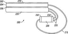
现在参考图6,支撑系统200的示例性实施方式包括多层盖板210、支撑床垫220和风机230。在某些示例性实施方式中,支撑床垫220是充气床垫。风机230包括通过进口连接构件215连接到多层盖板210的空气入口232。风机230还包括通过一对出口连接构件225连接到支撑床垫220的空气出口234。进口连接构件215和出口连接构件225可包括管子、柔性配管或允许空气在风机230和多层盖板210或支撑床垫220之间流动的任何其它装置。Referring now to FIG. 6 , an exemplary embodiment of a
在所示的示例性实施方式中,出口连接构件225每个都连接到支撑床垫220内的单独的腔。因此,单独的腔可被单独加压,以便于支撑床垫220所支撑的人的运动。这样的结构通常称为变压垫(APP)。在其它示例性实施方式中,支撑床垫220可只具有单腔,且风机230可具有在风机230和支撑床垫220之间的单个出口连接构件225。支撑床垫220因此可为变压垫类型的床垫,或利用空气来给床垫内的小室或腔充气或加压的任何其它类型的床垫。在某些示例性实施方式中,支撑床垫220可通过利用具有分立的基线压力(discrete base line pressures)的多个压力区来结合脉动,所述压力区交替变化为分立的基线压力之上和之下的压力。In the exemplary embodiment shown,
在图6所示的示例性实施方式中,多层盖板210相当于下面关于图8-10描述的盖板1001。在图6所示的示例性实施方式中,多层盖板210包括由可渗透蒸汽的材料形成的第一层202、由间隔材料形成的第二层204以及第三层206。在某些示例性实施方式中,第三层206由限制空气流并引导空气流通过间隔材料的材料形成。In the exemplary embodiment shown in Figure 6, the
支撑系统200配置成使得在工作期间,风机230抽吸空气通过多层盖板210和通过第二层204,并且还迫使或压入空气进入支撑床垫220中。通过结合这些功能,与利用分离的风机来抽吸空气通过盖板并迫使空气进入支撑床垫的实施方式相比,成本、空间要求、电要求和热生成减小了。支撑系统200因此提供了紧凑和有效的系统,其用于给支撑床垫220充气,并为结合支撑床垫使用的多层盖板210提供空气流。
在图6所示的示例性实施方式中,风机230在多层盖板210和支撑床垫220的外部。在有外部风机的示例性实施方式中,风机可方便地安装在可接近的位置,例如安装在支撑所述盖板和支撑床垫的床架的脚踏板处。In the exemplary embodiment shown in FIG. 6 , the
图7表示示例性实施方式的侧视图。在该示例性实施方式中,风机231被结合到支撑床垫221的外包层或外壳中。在图7所示的实施方式中,风机231与支撑床垫221构成整体,从而不需要风机231和支撑床垫221之间的连接构件。因为支撑床垫221放置成极接近于多层盖板211,所以也可减小风机231和多层盖板211之间的连接构件216的长度。在所示的示例性实施方式中,风机231用实质上气密的密封物连接到支撑床垫221,以便当空气进入或离开支撑床垫221时,空气不在风机231周围流动。在又一些示例性实施方式(未示出)中,构成整体的风机例如风机231可连接到多个出口连接构件,该出口连接构件连接到支撑床垫221内的多个腔。Figure 7 shows a side view of an exemplary embodiment. In the exemplary embodiment,
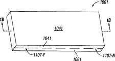
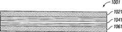
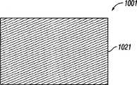
图8和9分别示出多层盖板1001的示例性实施方式的透视图和横截面视图。图10示出图8和9所示的多层盖板1001的第一层的顶视图。图11和12示出图8-10所示的盖板的第一层的各种实施方式的顶视图。如在图9中最佳示出的,多层盖板1001包括三层:第一层1021、第二层1041和第三层1061。在各种实施方式中,第一层、第二层和第三层1021、1041和1061每个都提供具有各种功能和特性的多层盖板1001,如这里将描述的。8 and 9 show perspective and cross-sectional views, respectively, of an exemplary embodiment of a
图8-12所示的多层盖板1001包括矩形形状。在其它示例性实施方式中,多层盖板1001可包括很多其它形状,包括但不限于圆形、卵形、方形、多边形和不规则形状。此外,多层盖板1001的每一层都可包括变化的长度、宽度和高度。在一些示例性实施方式中,例如,第二层1041可具有比第一和第三层1021和1061更大的宽度,而在其它示例性实施方式中,第三层1061可具有比第一和第二层1021和1041更大的宽度。The
在图8-10所示的示例性实施方式中,第一层1021由可渗透蒸汽、可渗透空气和不可渗透液体的材料形成,第二层1041由可在侧面渗透空气的柔性材料形成,而第三层1061由不可渗透蒸汽、空气和液体的材料形成。第一层1021的可渗透蒸汽的材料允许潮湿蒸汽、热及类似物通过第一层1021以蒸汽和/或空气的形式传递到多层盖板的第二层1041中,从而分散和移除来自患者和来自围绕患者的环境的湿气和热,同时防止液体通过第一层1021移到第二层1041中。在各种实施方式中,第一层1021可形成为使得第一层1021的全部或一部分可渗透空气、蒸汽和/或液体。例如,如图10所示,第一层1021的全部可渗透蒸汽,但不可渗透空气和液体。在图11中,第一层1021的就座区域(seat region)1031可渗透蒸汽和空气,而第一层1021的非就座部分1051不可渗透空气和蒸汽。此外,在各种示例性实施方式中,第一层1021可形成为使得一些部分比其它部分对蒸汽、空气和/或液体更有渗透性。如图12所示,例如,第一层1021的就座区域1031具有比第一层1021的非就座部分1051的渗透性更大的渗透性。因此,蒸汽和/或热在就座区域1031中将以比在非就座部分1051中的蒸汽和/或热转移速率更高的速率通过第一层1021转移。In the exemplary embodiment shown in Figures 8-10, the
如本领域的普通技术人员将认识到的,蒸汽和空气可携带有机体,例如细菌、病毒和其它可能有害的病菌。因此,并且如这里更详细描述的,在本公开的一些实施方式中,可提供一个或更多抗菌设备、制剂等来阻止、消灭、减轻、击退、诱捕和/或抑制可能有害的致病有机体,包括微生物有机体例如细菌、病毒、霉、霉菌、尘螨、真菌、微生物孢子、生物粘泥、原生动物、原生动物胞囊及类似物,因而从由患者和围绕患者的环境中分散和移除的空气和蒸汽中移除它们。此外,在各种实施方式中,多层盖板可包括具有抗菌功能的不同层。在一些实施方式中,例如,第一、第二和/或第三层1021、1041和1061可包括由银和/或其它抗菌剂形成的微粒、纤维、细丝等。其它示例性实施方式,包括图1-7和17-20中所公开的那些实施方式也可包括抗菌剂。As will be recognized by those of ordinary skill in the art, steam and air can carry organisms such as bacteria, viruses, and other potentially harmful germs. Accordingly, and as described in more detail herein, in some embodiments of the present disclosure, one or more antimicrobial devices, agents, etc. may be provided to prevent, eliminate, mitigate, repel, trap and/or inhibit potentially harmful pathogenic Organisms, including microbial organisms such as bacteria, viruses, molds, molds, dust mites, fungi, microbial spores, bioslime, protozoa, protozoan cysts, and the like, thus dispersed and migrated from the patient and the environment surrounding the patient Remove them from depleted air and steam. Additionally, in various embodiments, the multilayer cover sheet can include different layers that have antimicrobial functionality. In some embodiments, for example, the first, second, and/or
第一层1021可包括不同于在图8和9中示出和描述的那些特性的特性。例如,在各种示例性实施方式中,第一层1021可由可渗透蒸汽且不可渗透空气和液体的材料形成。在其它实施方式中,第一层1021可由可渗透空气、液体和蒸汽的材料形成。还设想了形成第一层1021的材料所展示的特性的其它组合。可用于形成第一层1021的、展示了蒸汽渗透性、液体不可渗透性和空气渗透性或不可渗透性的材料的一个例子包括商标名为
在各种示例性实施方式中,第二层1041可由各种材料形成,并可具有很多结构和形状,如这里描述的。在一些实施方式中,材料是柔性的。在这样的示例性实施方式中,柔性材料可包括抗压缩的特性,使得当柔性材料被例如躺在多层盖板上的患者的重量压缩时,柔性材料有返回到其原始形状的倾向,从而给予多层盖板支撑功能。柔性材料还可包括允许空气甚至在压缩下也可通过柔性材料横向移动的特性。In various exemplary embodiments, the
可用于形成第二层1041的材料的例子可包括但不限于微粒、细丝、铰合线、泡沫(例如开孔泡沫)以及其它形式的天然和合成聚合物,以及天然和合成材料例如棉纤维、聚酯纤维及类似物。其它材料可包括柔性金属和金属合金、形状记忆金属和合金以及形状记忆塑料。这些材料可包括弹性、超级弹性、线性弹性和/或形状记忆特性,而这些特性允许柔性材料折曲和弯曲,并在变化的条件(例如,压缩、应变、温度等)下形成变化的形状。Examples of materials that may be used to form the
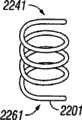
图13A-13D示出了多层盖板的柔性材料的各种示例性实施方式。在图13A-13D的各种实施方式中,柔性材料可包括很多横截面几何形状,包括但不限于圆形、卵形、多边形和不规则的几何形状。例如,如图13A-13D所示,柔性材料可包括铰合线构件(strand member)2161、泡沫构件2181、线圈构件2201或旋绕构件2221或其组合,每个都具有圆形横截面形状。图13A-14D中所示的每个实施方式都可单独地或组合地对躺在多层盖板上的患者提供支撑,可帮助降低患者和多层盖板之间的界面压力,并可允许空气在患者身下流动,以及可与支撑平台或支撑表面例如气垫结合起作用,以进一步减小患者和多层盖板之间的界面压力。13A-13D illustrate various exemplary embodiments of flexible materials for a multi-layer cover sheet. In the various embodiments of FIGS. 13A-13D , the flexible material can include many cross-sectional geometries including, but not limited to, circular, oval, polygonal, and irregular geometries. For example, as shown in FIGS. 13A-13D , the flexible material can include strand members 2161 ,
在每个图13A-13D中,柔性材料包括第一和第二端2241和2261。在各种示例性实施方式中,第一和第二端2241和2261可包括允许它们附接、连接、耦接、钩接、限制和/或锚定到多层盖板的部分的表面和/或结构,以将柔性构件固定到盖板,如关于图14A更详细描述的。在一些示例性实施方式中,形成图9所示的第二层1041的柔性材料没有连接到多层盖板1001,而是位于第一和第三层1021和1061之间,并通过将第一和第三层1021和1061紧固在一起,从而封闭第二层1041而固定在其中,如这里在下面将描述的。In each of FIGS. 13A-13D , the flexible material includes first and
在示例性实施方式中,柔性材料还可至少促进空气通过第二层的流动。例如,在各种示例性实施方式中,柔性材料可包括界定开口、通道和通路的结构,这些开口、通道和通路允许空气、蒸汽和液体通过第二层流动。在一个示例性实施方式中,柔性材料可包括不连续的结构,在该不连续的结构中,单独的部件例如单独的铰合线或纤维以及其它单独的部件不连接到彼此,而是连接到由第二层104的子层界定的一个或更多附接表面或结构,如将结合图14A-14D描述的。In an exemplary embodiment, the flexible material may also at least facilitate the flow of air through the second layer. For example, in various exemplary embodiments, the flexible material may include structures defining openings, channels, and passages that allow air, vapor, and liquids to flow through the second layer. In an exemplary embodiment, the flexible material may comprise a discontinuous structure in which individual components such as individual hinges or fibers and other individual components are not connected to each other but to One or more attachment surfaces or structures defined by sub-layers of the second layer 104, as will be described in connection with FIGS. 14A-14D.
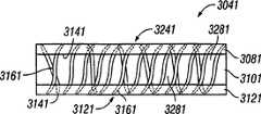
图14A-14D示出多层盖板的第二层的各种实施方式。在图14A所示的实施方式中,第二层3041包括第一子层3081、第二子层3101和第三子层3121。在本实施方式中,第一子层3081和第三子层3121可限定多个可附接第二子层3101的附接结构或表面3141。在各种示例性实施方式中,第二子层3101可为例如图13A-13D所示的任何柔性材料,或第二子层3101可由向患者提供支撑功能并能促进患者身下的空气的流动的其它材料形成。14A-14D illustrate various embodiments of the second layer of the multilayer cover sheet. In the embodiment shown in FIG. 14A , the
在各种示例性实施方式中,附接表面3141可包括内表面和/或外表面和/或第一和第三子层3081和3121的开口,柔性材料可直接附接、连接、锚定到这些子层,且空气、蒸汽和液体可通过这些子层传递。此外,第一和第三子层3081和3121可由很多不同的材料形成,每种材料都具有刚性、半刚性或柔韧的特性。In various exemplary embodiments, the
图14B示出图9所示的多层盖板1001的第二层3041的示例性实施方式的横截面视图。如图14B所示,第二层3041的第二子层3101包括由很多单独的铰合线构件3161形成的柔性材料,铰合线构件3161在第一和第三子层3081和3121之间延伸,并在第一和第三子层3081和3121上的不同位置处附接到第一和第三子层3081和3121。在本实施方式中,第一和第三子层3081和3121还包括柔性材料,以便第二层3041的所有三个子层可在压缩力下折曲或弯曲。如图14B所示,铰合线构件3161在第二子层3101内界定便于空气、蒸汽和液体通过第二层3041移动的通道和开口3281。此外,开口(在图14B中未示出)可由第一和第三子层3081和3121的表面界定,且因而也可便于空气和/或蒸汽和/或液体通过其移动。可用于形成多层盖板的第二层3041的材料的例子包括TYTEX GROUP制造的商标名为AirXTM的材料。FIG. 14B shows a cross-sectional view of an exemplary embodiment of the
图14C示出图8-12所示的多层盖板1001的第二层3041的另一示例性实施方式的横截面视图。如图14B所示,第二层3041包括第一、第二和第三子层3081、3101和3121。形成第二层3041的第二子层3101的柔性材料包括很多单独的泡沫构件3181。每个泡沫构件包括便于蒸汽、空气和液体通过泡沫构件3181移动的多孔或开孔结构。泡沫构件包括界定通路或开口3281的间隔开的结构,通路或开口3281进一步便于空气、蒸汽和液体通过其移动。此外,由第一和第三子层3081和3121界定的开口3301也便于蒸汽、空气和液体通过其移动。Figure 14C shows a cross-sectional view of another exemplary embodiment of the
在图14A-14C的各种示例性实施方式中,柔性材料可通过使用粘结剂及类似物以化学方法附接到第一和第三子层3081和3121,和/或通过使用紧固件例如缝针、扣钩、钩和环及类似物来机械附接,和/或通过使用焊接例如RF焊接和有关的方法来物理附接。如这里所述的,多层盖板的示例性实施方式的第一、第二和第三层以及第二层的子层的形状和尺寸可变化,且图14A-14C所示的示例性实施方式不限于如所示的矩形形状。可设想并可根据多层盖板的预期应用设计其它形状和尺寸。例如,在各种示例性实施方式中,盖板的形状和尺寸可根据它将使用的支撑表面或平台例如椅子来设计。In various exemplary embodiments of FIGS. 14A-14C , the flexible material may be chemically attached to the first and third sub-layers 3081 and 3121 through the use of adhesives and the like, and/or through the use of fasteners Mechanical attachment such as stitches, clasps, hooks and loops, and the like, and/or physical attachment through the use of welding such as RF welding and related methods. As described herein, the shape and size of the first, second and third layers and sub-layers of the second layer of the exemplary embodiment of the multilayer cover sheet can vary, and the exemplary implementation shown in FIGS. 14A-14C The manner is not limited to the rectangular shape as shown. Other shapes and dimensions are envisioned and can be designed depending on the intended application of the multilayer cover sheet. For example, in various exemplary embodiments, the cover can be shaped and sized according to the support surface or platform on which it will be used, such as a chair.
在图14D所示的示例性实施方式中,第二层3041的柔性材料包括具有开孔结构的单一泡沫构件3181。在该示例性实施方式中,单一泡沫构件3181实质上有与图8和9所示的多层盖板1001的第一和第三层102和104相同的周长尺寸。在图14D所示的示例性实施方式中,泡沫构件3181可位于第一和第三层102和106之间,并通过紧固第一和第三层102和106,从而将第二层3041封闭在多层盖板100的第一和第三层102和106内而被固定。在各种示例性实施方式中,泡沫构件3181可包括各种尺寸和形状。例如,在一些示例性实施方式中,单一泡沫构件3181具有小于第一和第三层1021和1061的周长的周长。In the exemplary embodiment shown in Figure 14D, the flexible material of the
再次参考图9,在各种示例性实施方式中,第一和第三层1021和1061可紧固在一起,以便紧固多层盖板的整个周界。在其它示例性实施方式中,可紧固第一和第三层1021和1061的周界的一部分,同时可不紧固剩余的部分。在这样的示例性实施方式中,与周界的未紧固部分相邻的紧固部分界定很多开口1107-1到1107-N(即,周界的未被紧固的区域),空气和蒸汽可通过这些开口移动。第一和第三层1021和1061的紧固可包括任何数量的技术,包括上面结合将第二层1041紧固到第一和第三层1021和1061而描述的那些技术。例如,在一些示例性实施方式中,第一和第三层1021和1061的部分通过缝合紧固在一起,而其它部分通过使用一个或更多纽扣和/或钩环紧固件(即,
在各种示例性实施方式中,第三层1061可由展示各种特性的各种不同的材料形成。在图9所示的示例性实施方式中,第三层1061由不可渗透蒸汽、不可渗透空气和不可渗透液体的材料形成。第三层1061的不可渗透的特性阻止蒸汽、空气和液体通过第三层1061传递,因而阻止空气、蒸汽和液体暴露给放置有多层盖板1001的支撑表面或平台。此外,第三层1061可起导向装置的作用,以向着未被紧固在一起的周界部分所界定的开口引导空气、蒸汽和液体,或从开口并向着细长构件引导空气,如将在这里描述的。在各种实施方式中,第三层也可起附接或连接层的作用,以将多层盖板附接到支撑表面或平台。例如,在各种实施方式中,第三层可包括可连接到支撑表面例如泡沫床垫的延伸部分(extension)。在这样的实施方式中,延伸部分可包在支撑表面周围,并被塞进在支撑表面下,或可使用各种紧固件例如这里描述的那些紧固件附接到支撑表面。在其它示例性实施方式中,第三层的外表面可包括很多紧固件,例如钩环紧固件。在这样的示例性实施方式中,支撑表面可设置有具有环结构的套,且第三层可包括具有钩结构的外层。可以设想用于将多层盖板附接到支撑表面或平台以便将多层盖板固定到其上的其它方法和机制。In various exemplary embodiments, the
在各种示例性实施方式中,多层盖板1001可为一次性使用的盖板或多次使用的盖板。如这里使用的,一次性使用的盖板是用于单个患者应用的盖板,其由可渗透蒸汽、空气和液体的材料形成,是用后即可丢弃的和/或不昂贵的和/或以低成本的方式制造和/或装配的,并被规定为在短时段例如1小时、1天或数天内对单个患者使用。如这里使用的,多次使用的盖板是用于多个患者应用的盖板,其通常由可渗透蒸汽、不可渗透液体和可渗透空气或不可渗透空气的材料形成,是可以重新使用的、可洗的,可使用各种技术(例如高压消毒、漂白等)被消毒,并通常具有比一次性使用的盖板更高的质量和更优良的工艺性,且被规定为由一个或更多患者在一段时间例如数天、数星期、数月和/或数年内使用。在各种示例性实施方式中,多次使用的盖板的制造和/或装配可能涉及比一次性使用的盖板更复杂和更昂贵的方法。用于形成一次性使用的盖板的材料的例子可包括但不限于非织造纸。用于形成可重新使用的盖板的材料的例子可包括但不限于
图15A-15C示出多层盖板的各种示例性实施方式和部件。图15A示出多层盖板400的透视图,盖板400具有与源434流体相通以移动空气的细长构件432。图15B示出与源434流体相通以在正压例如正压气泵444下移动空气的细长构件432的示例性实施方式。图15C示出与源流体相通以在负压(例如负压气泵446)下移动空气的细长构件的示例性实施方式。当细长构件432连接到正压气泵444或负压气泵446时,细长构件432起作用来便于空气在细长构件432内部、在多层盖板400内部以及在多层盖板400外部移动。例如,在包括正压气泵444的实施方式中,正压力被提供到细长构件432,以通过细长构件432移动空气并将空气移出细长构件432,用于分散在多层盖板400内,如下面在图15B中描述的。而且,在包括负压气泵446的示例性实施方式中,负的或减小的压力被提供到细长构件432,以将空气移到多层盖板400中,并通过多层盖板400将空气移到细长构件432中。在任一种情况下,空气的移动被提供到可产生和维持蒸汽的部分压力差的多层盖板,并因而帮助从患者以及从围绕患者的环境移除湿气和热。15A-15C illustrate various exemplary embodiments and components of a multi-layer cover sheet. Figure 15A shows a perspective view of a
在各种示例性实施方式中,负压气泵446的使用可帮助减少多层盖板400的翻腾(billowing)。当床垫或盖板在患者的重量下在邻近或接近于患者身体的外围的位置升高或膨胀时,可能出现翻腾。从负压气泵446产生的负压力可减小多层盖板翻腾的倾向,因为负压力往往使第一层102靠着第二层104平放,因而可帮助或促进空气正好在患者身下流动,而不是象在床垫或盖板翻腾时可能出现的那样在患者周围流动。In various exemplary embodiments, the use of a negative
如在图15A所示的示例性实施方式中示出的,多层盖板400包括细长构件432。如这里描述的,细长构件432可从多层盖板400的一侧并向着相同侧或不同侧延伸。在图15A所示的示例性实施方式中,例如,细长构件432从多层盖板400的第一侧436向着第二侧438延伸。在一些示例性实施方式中,细长构件432可从多层盖板400的第一侧440向着第四侧442延伸,或侧面的任何组合。如这里描述的,多层盖板可包括各种横截面形状,因而侧面的数量是可改变的。同样,在各种示例性实施方式中,细长构件可从一侧向着不同侧或多侧延伸,在示例性实施方式中有两个或更多侧。As shown in the exemplary embodiment shown in FIG. 15A , the
在各种示例性实施方式中,细长构件432可位于多层盖板400的不同位置处。例如,在一些示例性实施方式中,细长构件可接近或邻近多层盖板400的内表面(例如第一和第三层404和408的内表面)而定位,使得它邻近于多层盖板400的第三侧440的一段长度从多层盖板的第一侧436向着第二侧438延伸。在图15A所示的示例性实施方式中,细长构件432定位成使得它邻近于第三侧440以线性方式从第一侧436向着第二侧438延伸。在其它示例性实施方式中,细长构件432可定位成使得它以非线性方式并沿着多层盖板内部的单个平面或不同平面从第一侧436向着第二侧438延伸。例如,细长构件可以非线性方式并沿着多层盖板内部的不同平面定位,使得当它从多层盖板的第一侧436向着第二侧438延伸时,它弯曲并在很多方向上转动。在一个示例性实施方式中,细长构件432沿着接近和/或邻近于第一层404和/或第二层406的表面的区域延伸,在这些区域中,来自患者的湿气和/或热以相对于患者的其它部分更高的浓度呈现。这样的区域的非限制性的例子包括图11和12所示的就座区域103。如读者将认识到的,接近和/或邻近于这样的表面(例如就座区域103)定位细长构件可帮助增加蒸汽和热从患者转移的速率和效率,因为细长构件内空气的移动将接近或邻近于这样的表面,因而可在多层盖板的内部环境和多层盖板的外部环境之间产生蒸汽的可能较高的部分压力差。In various exemplary embodiments, the
在各种示例性实施方式中,细长构件432可具有各种横截面形状和尺寸,并可以各种方式配置。例如,在示例性实施方式中,细长构件432可包括但不限于圆形、卵形、多边形和不规则的横截面形状。在一些示例性实施方式中,当细长构件从第一侧436向着第二侧438延伸时,它可为线性的或直的,如图15A所示。在其它示例性实施方式中,当细长构件432从第一侧436向着第二侧438延伸时,它可包括一系列弯曲或转弯,如这里描述的。在各种示例性实施方式中,细长构件432可包括等于多层盖板400的长度的尺寸,而在其它示例性实施方式中,细长构件432可包括具有小于或大于多层盖板400的长度的尺寸。In various exemplary embodiments, the
如图15A所示,细长构件432位于多层盖板400内部。在一些实施方式中,细长构件可在多层盖板外部邻近于多层盖板而定位。而且,在其它实施方式中,细长构件可至少部分地位于多层盖板内,以便细长构件的一部分延伸到多层盖板的外部。As shown in FIG. 15A , the
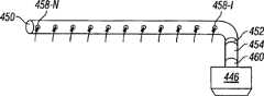
细长构件432可由单一材料或多种材料形成,并可具有很多不同结构。形成细长构件432的材料可包括但不限于聚合物、金属、金属合金以及包括天然和/或合成微粒、纤维、细丝等的材料或其组合。其它材料可包括柔性金属和金属合金、形状记忆金属和金属合金以及形状记忆塑料。结构可包括一个或更多外部层448和/或更多核心450。细长构件432的外部层448界定内腔(lumen)456。在一些示例性实施方式中,内腔456可包括位于内腔456内的核心450。在细长构件的各种实施方式中,外部层和/或核心可设计成便于空气通过细长主体移动。同样,在各种示例性实施方式中,外部层和/或核心可包括界定开口的结构,空气和/或蒸汽和/或液体可通过该开口传递。
在图15B和15C所示的示例性实施方式中,细长构件432具有由针织或编织的套形成的外部层448以及由柔性材料形成的核心450,例如图13A-13D所示的铰合线构件216、泡沫构件218、线圈构件220和旋绕构件222。在这样的示例性实施方式中,核心450还可包括多层结构,例如图14A所示的第二层3041的三个子层结构,其中第二子层由铰合线构件形成,例如图13A所示的铰合线构件216。还可以设想其它结构。例如,在一些示例性实施方式中,核心450可由适当的间隔材料形成,并由外部层432包围。In the exemplary embodiment shown in Figures 15B and 15C, the
如图15B和15C所示,细长构件432与源444或446流体相通,以在正或负压力下移动空气。在图15B所示的示例性实施方式中,在正压力下移动空气的源是正压气泵444。而且,在图15C所示的示例性实施方式中,在负压力下移动空气的源是负压气泵446。膨胀气泵444或真空气泵446都连接到导管452,而导管452又连接到细长构件432。在各种示例性实施方式中,连接气泵444和446、导管452和细长构件432可通过使用一个或更多连接部件来实现。例如,在一些实施方式中,多层盖板可包括连接到多层盖板的表面的连接部件454,连接部件454界定多层盖板400的内部环境和围绕多层盖板400的外部环境464之间的开口。在这样的示例性实施方式中,细长构件432可从多层盖板内部连接到导管452,且连接部件454可从多层盖板外部连接到导管452。As shown in Figures 15B and 15C, the
在各种示例性实施方式中,细长构件432的表面可限定允许空气进入或离开细长构件432的口458-1到458-N。例如,在图15B所示的示例性实施方式中,膨胀气泵444迫使空气通过细长构件432、通过口458-1到458-N(由箭头指示)而进入多层盖板中。而且,在图15C所示的示例性实施方式中,真空气泵446迫使空气从多层盖板进入负压气泵446中,在负压气泵446中,空气被散布回到环境中。In various exemplary embodiments, the surface of the
如这里描述的,本公开的示例性实施方式可包括很多抗菌设备、制剂等。抗菌设备的例子可包括机械设备例如过滤器、能量设备例如紫外光源以及化学制剂例如抗菌涂层。还可以设想其它抗菌设备和制剂。As described herein, exemplary embodiments of the present disclosure may include a number of antimicrobial devices, formulations, and the like. Examples of antimicrobial devices may include mechanical devices such as filters, energy devices such as ultraviolet light sources, and chemical agents such as antimicrobial coatings. Other antimicrobial devices and formulations are also contemplated.
例如,在图15C所示的示例性实施方式中,抗菌设备460例如过滤器可用于多层盖板。在一个示例性实施方式中,过滤器放置成使得空气在进入负压气泵之前通过过滤器传递。在该示例性实施方式中,减小了泵污染的可能性。在各种示例性实施方式中,抗菌设备460可位于下列位置中的一个或更多:在负压气泵446内部、邻近负压气泵446、在负压气泵446近侧和在负压气泵远侧。在各种示例性实施方式中,过滤器可设计成接收并容纳来自患者周围的环境和多层盖板内部的微粒和纤维物质。在各种示例性实施方式中,且如这里描述的,该物质可包括可能有害的病菌。For example, in the exemplary embodiment shown in Figure 15C, an
图16A和16B示出本公开的系统570的各种示例性实施方式。在图16A和16B的各种示例性实施方式中,系统570可包括位于支撑表面572上的多层盖板532。在各种示例性实施方式中,多层盖板可包括在图8、9和15A中示出的多层盖板。在各种示例性实施方式中,支撑表面572可包括很多表面和支撑平台。例如,支撑表面572可包括但不限于可充气的床垫、泡沫床垫、凝胶床垫和水床垫。其它支撑表面和平台包括床垫、


在图16A和16B所示的各种示例性实施方式中,多层盖板532包括由可渗透蒸汽的材料形成的第一层502、由柔性材料形成的第二层504和第三层506,柔性材料能促进蒸汽流通过第一层502进入第二层504。In various exemplary embodiments shown in FIGS. 16A and 16B , the multilayer cover sheet 532 includes a
在各种示例性实施方式中,系统还可包括移动多层盖板的内部和外部的空气的源。在一些实施方式中,移动空气的源可包括正压空气源,例如图15B所示的正压空气源444。而在其它实施方式中,移动空气的源可包括负压空气源,例如图15C所示的负压空气源446。In various exemplary embodiments, the system may also include a source for moving air inside and outside of the multilayer cover sheet. In some embodiments, the source of moving air can include a positive pressure air source, such as positive
如在图16A的示例性实施方式所示的,系统包括与细长构件(未示出)流体相通的正压空气源544,例如图15A-15C所示的细长构件。正压空气源544迫使空气(由箭头580指示)通过细长构件并从细长构件的表面所界定的开口出来,在细长构件中,空气散布到多层盖板532的内部,如这里描述的。空气在多层盖板内的移动在多层盖板532内部产生干燥的环境。由于在多层的内部区域和患者周围的环境582之间的蒸汽的部分压力差,可从患者身上移除在患者身上和周围的热和湿气。在患者身上和周围的湿气往往从患者身上和周围的高浓度区域移到多层盖板内的较低湿气浓度的区域。由正压源544引起的空气在多层盖板内的移动也移动蒸汽,该蒸汽通过多层盖板532的第一层传递而进入第二层,如这里描述的,在第二层中,蒸汽通过多层盖板中的开口散布到环境中。如这里描述的,部分压力差可导致空气的流动,以维持蒸汽的部分压力差,使得蒸汽通过可渗透蒸汽的第一层从多层盖板532的外部流到多层盖板532的内部。As shown in the exemplary embodiment of Figure 16A, the system includes a positive pressure air source 544 in fluid communication with an elongate member (not shown), such as the elongate member shown in Figures 15A-15C. Positive air source 544 forces air (indicated by arrow 580) through the elongated member and out of openings defined by the surfaces of the elongated member, where the air is distributed to the interior of multilayer cover sheet 532, as described herein of. The movement of air within the multilayer cover sheet creates a dry environment inside the multilayer cover sheet 532 . Due to the partial pressure difference of the steam between the interior region of the layers and the environment 582 surrounding the patient, heat and moisture on and around the patient may be removed from the patient. Moisture on and around the patient tends to migrate from areas of high concentration on and around the patient to areas of lower moisture concentration within the multilayer cover. The movement of air within the multi-layer cover sheet caused by the positive pressure source 544 also moves vapor that passes through the first layer of the multi-layer cover sheet 532 into the second layer, where, as described herein, The steam is dispersed into the environment through openings in the multi-layer cover. As described herein, the partial pressure differential may result in the flow of air to maintain a partial pressure differential of steam such that steam flows from the exterior of the multilayer cover sheet 532 to the interior of the multilayer cover sheet 532 through the vapor permeable first layer.
如在图16B的示例性实施方式中示出的,系统570包括与细长构件(未示出)流体相通的负压空气源546,例如图15A-15C所示的细长构件。负压空气源在多层盖板的内部区域中产生真空,这使空气580从多层盖板的外部移动并进入多层盖板中,在多层盖板中,空气经过患者身下并进入多层盖板的细长构件。细长构件向着抗菌设备和/或制剂560转移空气580和蒸汽和/或热,并接着进入负压源546。被处理的空气接着由负压源546散布回环境中。如这里描述的,部分压力差可导致空气的流动以维持蒸汽的部分压力差,使得蒸汽通过可渗透蒸汽的第一层从多层盖板532外部流到多层盖板532内部。As shown in the exemplary embodiment of Figure 16B, the system 570 includes a negative pressure air source 546 in fluid communication with an elongate member (not shown), such as the elongate member shown in Figures 15A-15C. The negative pressure air source creates a vacuum in the interior area of the multi-layer cover, which moves air 580 from the outside of the multi-layer cover and into the multi-layer cover, where the air passes under the patient and into An elongated member of a multilayer cover. The elongate member transfers air 580 and steam and/or heat toward the antimicrobial device and/or
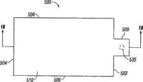
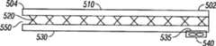
现在参考图17-20,盖板500的示例性实施方式包括第一端502、第二端504、第一侧506、第二侧508。所示的示例性实施方式包括可渗透蒸汽的顶层510、包括间隔材料的中间层520和底层530。在该实施方式中,盖板500还包括在底层530内并接近于第一端502的孔口535,以及与孔口535流体相通的风机540。在所示的示例性实施方式中,孔口535和风机540位于允许风机540放置在支撑床垫560的端部附近的突出部分或延伸部分509内(如图19和20所示)。在其它实施方式中,盖板500可不包括用于风机540的延伸部分。Referring now to FIGS. 17-20 , an exemplary embodiment of a
在图17-20中公开的示例性实施方式的工作原理类似于上面讨论的实施方式的工作原理。一般而言,潮湿蒸汽从患者(未示出)通过顶层510转移到包含在中间层520内的空气。风机540通过中间层520推或拉空气,以便潮湿蒸汽可从包含在中间层520内的空气移除。在某些示例性实施方式中,风机540是由Panasonic制造的零件号为FAL5F12LL的离心式12伏(额定)DC风扇。该特定的风机大约3英寸宽X3英寸高X1.1英寸厚,并且重量为大约3.5盎司。该风机还在12伏额定电压时产生大约8.8cfm的最大空气流和大约6.2mm H2O的最大气压。在工作期间,当风机两端的压力增加时,空气流将减少。使用这种风机的示例性实施方式一般在工作期间具有大约1.0到2.0cfm的空气流。在图23中提供了针对不同电压的气压、空气流和额定速度。如图23所示,该风机在大约2.0cfm的流速下提供小于6mmH2O的压差。Panasonic FAL5F12LL风机还产生低噪声水平(根据制造商的说明书为30.0dB-A)。The working principles of the exemplary embodiments disclosed in FIGS. 17-20 are similar to those of the embodiments discussed above. In general, moisture vapor is transferred from the patient (not shown) through the
在该示例性实施方式中,顶层510在第一端502以及在第一侧和第二侧506和508处结合到底层530。在所示的示例性实施方式中,顶层510和底层530形成实质上包围中间层520的外壳或包层,但顶层510和底层530在其整个周界周围没有被密封。这样的结构允许空气从外部环境进入盖板500并通过中间层520流动。如图18所示,第二端504是开口的,以便顶层510和底层530不连接在第二端504,且中间层520暴露于外部环境。In the exemplary embodiment,
在图18所示的示例性实施方式中,第二端504可构造成使得中间层520沿着整个第二端504暴露于外部环境。在其它实施方式中,可部分地密封第二端504(即,顶层510和底层530可沿着第二端504的一部分连接),以便中间层520接近于第二端504的一部分暴露于外部环境。在某些示例性实施方式中,可部分地密封第二端504,以便类似于孔口535的第二孔口设置在第二端504。在这样的实施方式中,风机540可放置在盖板500的第一端502或第二端504。这样的配置可通过允许风机540放置在第一端502或第二端504而提供盖板500的结构的灵活性,从而允许风机540放置在患者的头部端或足部端。在其它实施方式中,风机540可放置在不同的位置,且第二层520可在不同于第一端502或第二端504的位置处暴露于外部环境。In the exemplary embodiment shown in FIG. 18 , the
在又一些示例性实施方式中,第一层510和第二层530可包含相同的材料,并配置成形成包含中间层520的外壳。在其它示例性实施方式中,第一层510可包括在中心部分(最接近于患者的躯干)中具有高蒸汽渗透性的材料部分以及在不直接在患者躯干下的侧面区域中具有较低蒸汽渗透性(和也许较低的成本)的材料部分。在某些示例性实施方式中,第一层510还可为可渗透空气的,以允许空气除了通过第一层510和第三层530之间的开口流动以外还通过第一层510流动。In yet other exemplary embodiments, the
在示例性实施方式中,顶层510和底层530的没有被结合的部分是离风机540的远侧。在工作期间,这可允许风机540通过中间层520的较大部分推或拉空气,并从中间层520移除更多的潮湿蒸汽。在示例性实施方式中,盖板500可包括不可渗透液体的层。例如顶层510可为可渗透蒸汽、不可渗透液体的材料例如或底层530可为不可渗透液体的材料例如氨基甲酸乙酯。其它示例性实施方式可包括不同的材料或材料的组合。在图17-20中公开的实施方式还可包括类似于关于本公开中的其它实施方式所描述的那些部件的额外部件(例如抗菌设备,未示出)。In the exemplary embodiment, the portion of the
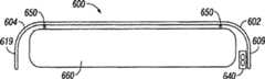
现在参考图21和22,盖板600的另一示例性实施方式包括拉链650以及除第一延伸部分609和第一孔口635之外的第二突出部分或延伸部分619以及第二孔口645。图21所示的实施方式的其余方面相当于在图17-20的盖板500中描述的那些方面。例如,盖板600包括第一端602、第二端604、第一侧606、第二侧608、以及第一、第二和第三层610、620和630。Referring now to FIGS. 21 and 22 , another exemplary embodiment of a
在图21的示例性实施方式中,拉链650通常在盖板600的周界周围延伸,但不在延伸部分609或619的周围延伸。在示例性实施方式中,拉链650通过任何适当的方法例如缝合或RF焊接连接到第三层630。在示例性实施方式中,拉链650配置成使得它可拉到在床垫或其它支撑系统上的相应拉链。在特定的示例性实施方式中,拉链650可配置成拉到在KineticConcepts公司所提供的
在某些示例性实施方式中,第一层610和第二层630可连接(例如通过缝合或焊接)在接缝615处。如图21所示,接缝615在盖板600的整个周界周围延伸,包括延伸部分609和619。第二层620以及孔口635和645在接缝615所围绕的区域内部。风机(未示出)可连接到孔口635或孔口645,以将负或正气压提供到由第一层610、第三层630和接缝615产生的腔。如果使用负气压风机,则外部空气可从孔口635或645(风机的相对面)抽出,通过第二层620抽出,并通过风机排出。如果使用正气压风机,则空气可从风机所连接的孔口、通过第二层620并从与风机相对的孔口被推出。在图21-22中公开的实施方式还可包括类似于关于本公开中的其它实施方式所描述的那些部件的额外部件(例如抗菌设备,未示出)。In certain exemplary embodiments, first layer 610 and second layer 630 may be joined (eg, by stitching or welding) at seam 615 . As shown in FIG. 21 , seam 615 extends around the entire perimeter of
Claims (51)
Applications Claiming Priority (7)
| Application Number | Priority Date | Filing Date | Title |
|---|---|---|---|
| US79952606P | 2006-05-11 | 2006-05-11 | |
| US60/799,526 | 2006-05-11 | ||
| US87421006P | 2006-12-11 | 2006-12-11 | |
| US60/874,210 | 2006-12-11 | ||
| US11/746,953 | 2007-05-10 | ||
| US11/746,953US7914611B2 (en) | 2006-05-11 | 2007-05-10 | Multi-layered support system |
| PCT/US2007/068801WO2007134246A2 (en) | 2006-05-11 | 2007-05-11 | Multi-layered support system |
Publications (2)
| Publication Number | Publication Date |
|---|---|
| CN101442924Atrue CN101442924A (en) | 2009-05-27 |
| CN101442924B CN101442924B (en) | 2011-10-12 |
Family
ID=38683898
Family Applications (1)
| Application Number | Title | Priority Date | Filing Date |
|---|---|---|---|
| CN2007800169963AActiveCN101442924B (en) | 2006-05-11 | 2007-05-11 | multi-layer support system |
Country Status (11)
| Country | Link |
|---|---|
| US (3) | US7914611B2 (en) |
| EP (2) | EP2015655B1 (en) |
| JP (2) | JP5108874B2 (en) |
| CN (1) | CN101442924B (en) |
| AU (2) | AU2007249236B2 (en) |
| CA (1) | CA2651960C (en) |
| DK (2) | DK2526836T3 (en) |
| PL (1) | PL2526836T3 (en) |
| TW (1) | TWI440554B (en) |
| WO (1) | WO2007134246A2 (en) |
| ZA (1) | ZA200810095B (en) |
Cited By (10)
| Publication number | Priority date | Publication date | Assignee | Title |
|---|---|---|---|---|
| CN102892334A (en)* | 2010-05-27 | 2013-01-23 | 凯希特许有限公司 | Multi-layer support system |
| CN103906494A (en)* | 2011-07-28 | 2014-07-02 | 亨特来夫工业技术有限公司 | Multi-layer support system |
| CN104066411A (en)* | 2012-01-20 | 2014-09-24 | 亨特来夫工业技术有限公司 | System for support and thermal control |
| CN104114139A (en)* | 2011-10-03 | 2014-10-22 | 亨特来夫工业技术有限公司 | Multi-layered support system |
| CN104582663A (en)* | 2012-08-21 | 2015-04-29 | 亨特来夫工业技术有限公司 | Patient transport device |
| CN104582664A (en)* | 2012-08-30 | 2015-04-29 | 亨特来夫工业技术有限公司 | Multi-Layer Patient Support Cover Sheet System |
| CN106102520A (en)* | 2014-01-13 | 2016-11-09 | 百德盖尔有限责任公司 | Environmental bed with heat recovery system |
| TWI636752B (en)* | 2017-03-30 | 2018-10-01 | 郭春富 | Cushion |
| CN104602660B (en)* | 2012-09-07 | 2018-12-18 | 亨特来夫工业技术有限公司 | Low air loss (LAL) patient support apparatus and method |
| CN109276385A (en)* | 2017-07-21 | 2019-01-29 | 希尔-罗姆服务公司 | In response to the patient cooling system of height of head |
Families Citing this family (186)
| Publication number | Priority date | Publication date | Assignee | Title |
|---|---|---|---|---|
| EP1076499B1 (en)* | 1998-05-06 | 2004-07-21 | Hill-Rom Services, Inc. | Mattress or cushion structure |
| US9462893B2 (en) | 1998-05-06 | 2016-10-11 | Hill-Rom Services, Inc. | Cover system for a patient support surface |
| US7240386B1 (en)* | 2004-05-20 | 2007-07-10 | King Koil Licensing Company, Inc. | Multi-layer mattress with an air filtration foundation |
| US7587901B2 (en) | 2004-12-20 | 2009-09-15 | Amerigon Incorporated | Control system for thermal module in vehicle |
| US7779625B2 (en) | 2006-05-11 | 2010-08-24 | Kalypto Medical, Inc. | Device and method for wound therapy |
| US7914611B2 (en)* | 2006-05-11 | 2011-03-29 | Kci Licensing, Inc. | Multi-layered support system |
| US20080087316A1 (en) | 2006-10-12 | 2008-04-17 | Masa Inaba | Thermoelectric device with internal sensor |
| EP2567637B1 (en) | 2006-10-13 | 2014-08-06 | Gentherm Incorporated | Air conditioning bed |
| FR2907646B1 (en)* | 2006-10-26 | 2009-02-06 | Hill Rom Ind S A Sa | DEVICE AND METHOD FOR CONTROLLING MOISTURE AT THE SURFACE OF A MATTRESS TYPE SUPPORT ELEMENT. |
| WO2009036077A1 (en) | 2007-09-10 | 2009-03-19 | Amerigon, Inc. | Operational control schemes for ventilated seat or bed assemblies |
| US8011041B2 (en)* | 2007-09-19 | 2011-09-06 | Persimmon Scientific, Inc. | Devices for prevention of pressure ulcers |
| US9125497B2 (en) | 2007-10-15 | 2015-09-08 | Gentherm Incorporated | Climate controlled bed assembly with intermediate layer |
| US8181290B2 (en) | 2008-07-18 | 2012-05-22 | Amerigon Incorporated | Climate controlled bed assembly |
| ES2715605T3 (en) | 2007-11-21 | 2019-06-05 | Smith & Nephew | Wound dressing |
| EP2214612B1 (en) | 2007-11-21 | 2019-05-01 | Smith & Nephew PLC | Wound dressing |
| CN114715003A (en) | 2008-02-01 | 2022-07-08 | 金瑟姆股份公司 | Condensation and humidity sensor for thermoelectric devices |
| GB2458892B (en)* | 2008-03-31 | 2012-11-28 | Talley Group Ltd | Temperature controlled mattress system |
| US8856993B2 (en)* | 2008-04-15 | 2014-10-14 | Hill-Rom Services, Inc. | Temperature and moisture regulating topper for non-powered person-support surfaces |
| US8555440B2 (en)* | 2008-04-30 | 2013-10-15 | Randall J. Lewis | Patient lifter with intra operative controlled temperature air delivery system |
| US20120079656A1 (en)* | 2008-04-30 | 2012-04-05 | Lewis Randall J | Patient lifter with intraoperative controlled temperature air delivery system |
| US10092470B2 (en)* | 2008-04-30 | 2018-10-09 | Randall J. Lewis | Patient lifter with intraoperative controlled temperature air delivery system |
| US8490226B2 (en) | 2008-09-19 | 2013-07-23 | Diacor, Inc. | Systems for patient transfer, devices for movement of a patient, and methods for transferring a patient for treatment |
| JP4961522B2 (en)* | 2008-09-21 | 2012-06-27 | 善雄 鈴木 | Eco sleep bedding |
| EP2348922B1 (en)* | 2008-09-24 | 2014-01-29 | Gilbert W. Mckenna | Subject support apparatus |
| US8451129B2 (en)* | 2008-11-03 | 2013-05-28 | Medline Industries, Inc. | Patient monitoring system with unitary structure and method |
| AU2009316562B2 (en)* | 2008-11-19 | 2015-06-11 | Arjo Ip Holding Ab | Multi-layered support system and method thereof |
| WO2010078047A2 (en) | 2008-12-17 | 2010-07-08 | Stryker Corporation | Patient support |
| US8893329B2 (en)* | 2009-05-06 | 2014-11-25 | Gentherm Incorporated | Control schemes and features for climate-controlled beds |
| US8332975B2 (en) | 2009-08-31 | 2012-12-18 | Gentherm Incorporated | Climate-controlled topper member for medical beds |
| US20110092890A1 (en)* | 2009-10-20 | 2011-04-21 | Stryker Corporation | Microclimate management system |
| US8146184B2 (en)* | 2009-11-16 | 2012-04-03 | Feng Yi Outdoor Leisure Equipment Enterprise Co., Ltd. | Inflatable cushion having a warming function |
| US9820904B2 (en) | 2011-07-13 | 2017-11-21 | Stryker Corporation | Patient/invalid handling support |
| SE1400093A1 (en)* | 2010-02-01 | 2014-02-19 | Hasta Group Ab | Mattress |
| EP2912974A3 (en) | 2010-05-28 | 2015-12-09 | Marlow Industries, Inc. | System for thermoelectric personal comfort controlled bedding |
| US9044367B2 (en) | 2010-06-12 | 2015-06-02 | American Home Health Care, Inc. | Patient weighing and bed exit monitoring |
| US8640763B1 (en)* | 2010-08-17 | 2014-02-04 | Judith C. Laengle | Device and method for facilitating the delivery or moving of oversized furniture items |
| US9027629B1 (en)* | 2010-08-17 | 2015-05-12 | Judith C Laengle | Device and method for facilitating the delivery or moving of oversized furniture items |
| DE102010039958A1 (en)* | 2010-08-30 | 2012-03-01 | Heinrich Essers Gmbh & Co. Kg | Mattress with a spacer textile |
| EP2624726A4 (en)* | 2010-10-07 | 2014-03-12 | Banyan Licensing L L C | Pillow for use with assisted breathing masks |
| US8918930B2 (en) | 2011-01-04 | 2014-12-30 | Huntleigh Technology Limited | Methods and apparatuses for low-air-loss (LAL) coverlets and airflow units for coverlets |
| AU2012312290B2 (en)* | 2011-09-21 | 2016-09-29 | Stryker Corporation | Patient/invalid support |
| US20130074272A1 (en)* | 2011-09-23 | 2013-03-28 | Charles A. Lachenbruch | Moisture Management and Transport Cover |
| WO2013052823A1 (en) | 2011-10-07 | 2013-04-11 | Gentherm Incorporated | Thermoelectric device controls and methods |
| US9119754B2 (en)* | 2011-10-08 | 2015-09-01 | Michael Dennis | Mattress overlay system with positionally adjustable, lateral ramp-wedge bolster structure |
| AU2012331625B2 (en)* | 2011-11-03 | 2015-04-23 | Shl Healthcare Ab | Mattress system |
| US9615983B2 (en)* | 2011-11-14 | 2017-04-11 | Stryker Corporation | Medical equipment with antimicrobial components and/or system |
| US20140366277A1 (en)* | 2012-01-26 | 2014-12-18 | Huntleigh Technology Limited | Pressure measurement systems and methods with moisture vapor control |
| US9989267B2 (en) | 2012-02-10 | 2018-06-05 | Gentherm Incorporated | Moisture abatement in heating operation of climate controlled systems |
| EP2805646B1 (en)* | 2012-02-14 | 2016-01-06 | Hill-Rom Services, Inc. | Topper and bed with tatgeted fluid dlow distribution and preferential fluid flow distribution |
| US9131780B2 (en) | 2012-02-14 | 2015-09-15 | Hill-Rom Services, Inc. | Topper with preferential fluid flow distribution |
| US20130212808A1 (en)* | 2012-02-21 | 2013-08-22 | Charles A. Lachenbruch | Topper with Targeted Fluid Flow Distribution |
| JP6250571B2 (en) | 2012-03-12 | 2017-12-20 | スミス アンド ネフュー ピーエルシーSmith & Nephew Public Limited Company | Pressure reducing apparatus and method |
| US20130255699A1 (en)* | 2012-04-02 | 2013-10-03 | TurnCare, Inc. | Patient-orienting alternating pressure decubitus prevention support apparatus |
| US20150074905A1 (en) | 2012-04-17 | 2015-03-19 | Climazleeper Holding Aps | Means of transport with battery driven cooling of a sleeping driver |
| US9009892B2 (en)* | 2012-05-10 | 2015-04-21 | Hill-Rom Services, Inc. | Occupant support and topper assembly with liquid removal and microclimate control capabilities |
| JP6017686B2 (en) | 2012-06-21 | 2016-11-02 | ヒル−ロム サービシズ,インコーポレイテッド | Patient holding system and method of use |
| US9833369B2 (en) | 2012-06-21 | 2017-12-05 | Hill-Rom Services, Inc. | Patient support systems and methods of use |
| US9228885B2 (en)* | 2012-06-21 | 2016-01-05 | Hill-Rom Services, Inc. | Patient support systems and methods of use |
| US10047981B2 (en) | 2012-07-30 | 2018-08-14 | Marlow Industries, Inc. | System and method for thermoelectric personal comfort controlled bedding |
| US10051973B2 (en)* | 2012-07-31 | 2018-08-21 | Sealy Technology Llc | Air conditioned mattresses |
| US9572433B2 (en)* | 2012-08-15 | 2017-02-21 | Hill-Rom Services, Inc. | Systems and methods for directing fluid flow in a mattress |
| GB2505935A (en)* | 2012-09-17 | 2014-03-19 | Michael Barry Allaway | Waterproof puncture-resistant mattress cover |
| US9131781B2 (en) | 2012-12-27 | 2015-09-15 | Select Comfort Corporation | Distribution pad for a temperature control system |
| US9326616B2 (en)* | 2013-01-10 | 2016-05-03 | Dreamwell, Ltd. | Active airflow temperature controlled bedding systems |
| US9463124B2 (en) | 2013-01-15 | 2016-10-11 | Hill-Rom Services, Inc. | Microclimate system for a patient support apparatus |
| US9289072B2 (en) | 2013-01-18 | 2016-03-22 | Fxi, Inc. | Compressible or retractable support for air blower cavity of air flow mattress |
| US9138064B2 (en)* | 2013-01-18 | 2015-09-22 | Fxi, Inc. | Mattress with combination of pressure redistribution and internal air flow guides |
| US9392875B2 (en)* | 2013-01-18 | 2016-07-19 | Fxi, Inc. | Body support system with combination of pressure redistribution and internal air flow guide(s) for withdrawing heat and moisture away from body reclining on support surface of body support system |
| US9456780B2 (en) | 2013-02-07 | 2016-10-04 | Hill-Rom Services, Inc. | Dynamic therapy delivery system |
| US9333136B2 (en) | 2013-02-28 | 2016-05-10 | Hill-Rom Services, Inc. | Sensors in a mattress cover |
| US9433300B2 (en) | 2013-02-28 | 2016-09-06 | Hill-Rom Services, Inc. | Topper for a patient surface |
| US20140259400A1 (en)* | 2013-03-13 | 2014-09-18 | Stryker Corporation | Patient support with microclimate management system |
| US9402612B2 (en)* | 2013-03-14 | 2016-08-02 | Precient Surgical, Inc. | Methods and devices for the prevention of incisional surgical site infections |
| US11399996B2 (en) | 2013-10-16 | 2022-08-02 | Kuiper Kamradt Llc | Automatic patient turning and lifting method, system, and apparatus |
| US9662962B2 (en) | 2013-11-05 | 2017-05-30 | Gentherm Incorporated | Vehicle headliner assembly for zonal comfort |
| US9693920B2 (en) | 2013-11-27 | 2017-07-04 | Sage Products, Llc | Apparatus and system for turning and positioning a patient |
| WO2015123585A1 (en) | 2014-02-14 | 2015-08-20 | Gentherm Incorporated | Conductive convective climate controlled seat |
| US20150282631A1 (en)* | 2014-04-08 | 2015-10-08 | Jim Creamer | Temperature Control Pad |
| US20170202362A1 (en)* | 2014-04-10 | 2017-07-20 | Neven Sleep, Llc | Ventilating sleep system |
| US9596945B2 (en)* | 2014-04-16 | 2017-03-21 | Tempur-Pedic Management, Llc | Support cushions and methods for dissipating heat away from the same |
| US9888785B2 (en) | 2014-04-21 | 2018-02-13 | Casper Sleep Inc. | Mattress |
| WO2015199667A1 (en)* | 2014-06-25 | 2015-12-30 | Tempur-Pedic Management, Llc | Support cushion cover assemblies for removing heat and humidity |
| US9504620B2 (en) | 2014-07-23 | 2016-11-29 | American Sterilizer Company | Method of controlling a pressurized mattress system for a support structure |
| WO2016020883A1 (en) | 2014-08-07 | 2016-02-11 | Fakhrizadeh Mohammad | Multi-functional and multipositional bed |
| DE102014015284B4 (en)* | 2014-10-16 | 2018-01-18 | Fraunhofer-Gesellschaft zur Förderung der angewandten Forschung e.V. | Cushion for active rearrangement of a human head |
| US10342358B1 (en) | 2014-10-16 | 2019-07-09 | Sleep Number Corporation | Bed with integrated components and features |
| WO2016077843A1 (en) | 2014-11-14 | 2016-05-19 | Cauchy Charles J | Heating and cooling technologies |
| US11639816B2 (en) | 2014-11-14 | 2023-05-02 | Gentherm Incorporated | Heating and cooling technologies including temperature regulating pad wrap and technologies with liquid system |
| US11857004B2 (en) | 2014-11-14 | 2024-01-02 | Gentherm Incorporated | Heating and cooling technologies |
| WO2016086030A1 (en)* | 2014-11-24 | 2016-06-02 | Huntleigh Technology Limited | Moisture control system |
| US11833091B2 (en)* | 2014-11-24 | 2023-12-05 | Arjo Ip Holding Ab | Moisture control coverlet |
| ES2880337T3 (en)* | 2014-12-02 | 2021-11-24 | Climazleeper Holding Aps | Ventilation or heating / cooling mattress |
| US20160157617A1 (en)* | 2014-12-04 | 2016-06-09 | Lear Corporation | Thoracic region comfort seating system |
| KR101686713B1 (en) | 2014-12-08 | 2016-12-14 | 엘지전자 주식회사 | Method for mamufactuing quantum dot-polymer complex, quantum dot-polymer complex, light conversion film, baclight unit and display devive comprising the same |
| ES2659314T3 (en)* | 2015-02-09 | 2018-03-14 | Trafalgar Associates, LLC | Fire-resistant mattresses, fire-resistant mattress cover materials |
| US9943173B2 (en) | 2015-02-13 | 2018-04-17 | L&P Property Management Company | Pocketed spring comfort layer and method of making same |
| US9968202B2 (en) | 2015-02-13 | 2018-05-15 | L&P Property Management Company | Pocketed spring comfort layer and method of making same |
| US10813462B2 (en) | 2015-02-13 | 2020-10-27 | L&P Property Management Company | Pocketed spring comfort layer and method of making same |
| US10405665B2 (en) | 2015-02-13 | 2019-09-10 | L&P Property Management Company | Pocketed spring comfort layer and method of making same |
| US9913770B2 (en)* | 2015-02-17 | 2018-03-13 | Hill-Rom Services, Inc. | Climate management topper with shape change actuators for regulating coolant distribution |
| US9226863B1 (en) | 2015-03-30 | 2016-01-05 | King Saud University | Mattress for relieving pressure ulcers |
| DK3288508T3 (en) | 2015-04-27 | 2020-03-09 | Smith & Nephew | REDUCED PRESSURE DEVICES |
| US10765576B2 (en) | 2015-08-18 | 2020-09-08 | Sage Products, Llc | Apparatus and system for boosting, transferring, turning and positioning a patient |
| US10624804B2 (en) | 2015-08-18 | 2020-04-21 | Hill-Rom Services, Inc. | Microclimate management airflow control based on incontinence detection |
| US9849053B2 (en) | 2015-08-18 | 2017-12-26 | Sage Products, Llc | Apparatus and system for boosting, transferring, turning and positioning a patient |
| US10507158B2 (en) | 2016-02-18 | 2019-12-17 | Hill-Rom Services, Inc. | Patient support apparatus having an integrated limb compression device |
| EP3426206B1 (en) | 2016-03-07 | 2023-05-10 | Smith & Nephew plc | Wound treatment apparatuses and methods with negative pressure source integrated into wound dressing |
| JP6632440B2 (en)* | 2016-03-22 | 2020-01-22 | 株式会社タチエス | Vehicle seat and manufacturing method thereof |
| AU2017246574A1 (en) | 2016-04-04 | 2018-10-25 | Ashley Furniture Industries, Inc. | Mattress permitting airflow for heating and cooling |
| CA3022184A1 (en) | 2016-04-26 | 2017-11-02 | Smith & Nephew Plc | Wound dressings and methods of use with integrated negative pressure source having a fluid ingress inhibition component |
| CN107319861B (en)* | 2016-04-28 | 2018-11-06 | 张弘毅 | Intelligent temperature control quilt |
| WO2017191158A1 (en) | 2016-05-03 | 2017-11-09 | Smith & Nephew Plc | Systems and methods for driving negative pressure sources in negative pressure therapy systems |
| CA3038206A1 (en) | 2016-05-03 | 2017-11-09 | Smith & Nephew Plc | Optimizing power transfer to negative pressure sources in negative pressure therapy systems |
| US11096831B2 (en) | 2016-05-03 | 2021-08-24 | Smith & Nephew Plc | Negative pressure wound therapy device activation and control |
| WO2018022760A1 (en)* | 2016-07-27 | 2018-02-01 | Philip Sherman | Climate controlled mattress system |
| US11259958B2 (en)* | 2016-08-11 | 2022-03-01 | Stryker Corporation | Thermal therapy devices |
| WO2018037075A1 (en) | 2016-08-25 | 2018-03-01 | Smith & Nephew Plc | Absorbent negative pressure wound therapy dressing |
| KR102333637B1 (en)* | 2016-09-14 | 2021-12-01 | 데이비드 엘. 프랭크 | Advanced dielectric energy storage device and method of fabrication |
| EP3519001B1 (en) | 2016-09-30 | 2025-05-21 | Smith & Nephew plc | Negative pressure wound treatment apparatuses and methods with integrated electronics |
| US10918547B2 (en) | 2016-11-23 | 2021-02-16 | Ehob, Inc. | Pediatric air mattress and system |
| EP3551244A1 (en) | 2016-12-12 | 2019-10-16 | Smith & Nephew PLC | Pressure wound therapy status indication via external device |
| US9888782B1 (en) | 2017-01-27 | 2018-02-13 | Eastern Sleep Products Company | Temperature controlled mattress system |
| US20200037796A1 (en)* | 2017-02-13 | 2020-02-06 | Reissi Holdings Pty Ltd | Pillow |
| US10827845B2 (en) | 2017-02-24 | 2020-11-10 | Sealy Technology, Llc | Support cushions including a support insert with a bag for directing air flow, and methods for controlling surface temperature of same |
| EP3592312B1 (en) | 2017-03-08 | 2024-01-10 | Smith & Nephew plc | Negative pressure wound therapy device control in presence of fault condition |
| DE102017002417A1 (en)* | 2017-03-14 | 2018-09-20 | Jacob Hendrik Bolt | bed pad |
| IT201700044173A1 (en) | 2017-04-21 | 2018-10-21 | Me Res Srl | MATTRESS |
| JP7121050B2 (en) | 2017-05-09 | 2022-08-17 | スミス アンド ネフュー ピーエルシー | Redundant control of negative pressure wound therapy systems |
| WO2018232012A1 (en) | 2017-06-13 | 2018-12-20 | Sage Products, Llc | Patient positioning and support system |
| EP3641962A4 (en)* | 2017-06-20 | 2020-11-25 | L&P Property Management Company | Pocketed spring comfort layer and method of making same |
| US11116326B2 (en) | 2017-08-14 | 2021-09-14 | Casper Sleep Inc. | Mattress containing ergonomic and firmness-regulating endoskeleton |
| US10772438B2 (en) | 2017-08-23 | 2020-09-15 | Sleep Number Corporation | Air system for a bed |
| GB201718070D0 (en) | 2017-11-01 | 2017-12-13 | Smith & Nephew | Negative pressure wound treatment apparatuses and methods with integrated electronics |
| CA3074780A1 (en) | 2017-09-13 | 2019-03-21 | Smith & Nephew Plc | Negative pressure wound treatment apparatuses and methods with integrated electronics |
| GB201718054D0 (en) | 2017-11-01 | 2017-12-13 | Smith & Nephew | Sterilization of integrated negative pressure wound treatment apparatuses and sterilization methods |
| GB201718072D0 (en) | 2017-11-01 | 2017-12-13 | Smith & Nephew | Negative pressure wound treatment apparatuses and methods with integrated electronics |
| US11497653B2 (en) | 2017-11-01 | 2022-11-15 | Smith & Nephew Plc | Negative pressure wound treatment apparatuses and methods with integrated electronics |
| WO2019094502A1 (en) | 2017-11-07 | 2019-05-16 | Prescient Surgical, Inc. | Methods and apparatus for prevention of surgical site infection |
| BR112020010232B1 (en)* | 2017-11-21 | 2023-01-17 | Vincenzo Buoninfante | MATTRESS |
| US11246775B2 (en) | 2017-12-28 | 2022-02-15 | Stryker Corporation | Patient turning device for a patient support apparatus |
| US11173085B2 (en) | 2017-12-28 | 2021-11-16 | Stryker Corporation | Mattress cover for a mattress providing rotation therapy to a patient |
| AU2019201323B2 (en) | 2018-02-27 | 2020-03-05 | Hill-Rom Services, Inc. | Patient support surface control, end of life indication, and x-ray cassette sleeve |
| US20190269251A1 (en) | 2018-03-01 | 2019-09-05 | L&P Property Management Company | Posturized Pocketed Spring Comfort Layer |
| WO2019209733A1 (en) | 2018-04-23 | 2019-10-31 | Casper Sleep Inc. | Temperature-regulating mattress |
| IT201800005532A1 (en)* | 2018-05-21 | 2019-11-21 | ANTI-DECUBITUS DEVICE, ANTI-DECUBITUS BED, METHOD OF MAKING AN ANTI-DECUBITUS MATTRESS | |
| US11160386B2 (en) | 2018-06-29 | 2021-11-02 | Tempur World, Llc | Body support cushion with ventilation system |
| US20200029703A1 (en)* | 2018-07-27 | 2020-01-30 | Bedgear, Llc | Bedding system and method |
| US11223004B2 (en) | 2018-07-30 | 2022-01-11 | Gentherm Incorporated | Thermoelectric device having a polymeric coating |
| WO2020041493A1 (en) | 2018-08-21 | 2020-02-27 | Sage Products, Llc | Systems and methods for lifting and positioning a patient |
| USD898925S1 (en) | 2018-09-13 | 2020-10-13 | Smith & Nephew Plc | Medical dressing |
| USD888964S1 (en) | 2018-09-28 | 2020-06-30 | Stryker Corporation | Crib assembly for a patient support |
| US11219567B2 (en) | 2018-09-28 | 2022-01-11 | Stryker Corporation | Patient support |
| USD888963S1 (en) | 2018-09-28 | 2020-06-30 | Stryker Corporation | Cover assembly for a patient support |
| USD877915S1 (en) | 2018-09-28 | 2020-03-10 | Stryker Corporation | Crib assembly |
| USD879966S1 (en) | 2018-09-28 | 2020-03-31 | Stryker Corporation | Crib assembly |
| USD888962S1 (en) | 2018-09-28 | 2020-06-30 | Stryker Corporation | Cover assembly for a patient support |
| USD977109S1 (en) | 2018-09-28 | 2023-01-31 | Stryker Corporation | Crib assembly for a patient support |
| USD901940S1 (en) | 2018-09-28 | 2020-11-17 | Stryker Corporation | Patient support |
| US11241349B2 (en) | 2018-09-28 | 2022-02-08 | Stryker Corporation | Patient support including a connector assembly |
| USD890914S1 (en) | 2018-10-31 | 2020-07-21 | Stryker Corporation | Pump |
| USD893543S1 (en) | 2018-10-31 | 2020-08-18 | Stryker Corporation | Display screen with graphical user interface |
| USD894226S1 (en) | 2018-10-31 | 2020-08-25 | Stryker Corporation | Display screen or portion thereof with graphical user interface |
| USD892159S1 (en) | 2018-10-31 | 2020-08-04 | Stryker Corporation | Display screen with animated graphical user interface |
| US11559451B2 (en) | 2018-10-31 | 2023-01-24 | Stryker Corporation | Fluid source for supplying fluid to therapy devices |
| USD894956S1 (en) | 2018-10-31 | 2020-09-01 | Stryker Corporation | Display screen or portion thereof with graphical user interface |
| USD894223S1 (en) | 2018-10-31 | 2020-08-25 | Stryker Corporation | Display screen with animated graphical user interface |
| USD894957S1 (en) | 2018-10-31 | 2020-09-01 | Stryker Corporation | Display screen or portion thereof with graphical user interface |
| CN113167510B (en) | 2018-11-30 | 2025-10-03 | 金瑟姆股份公司 | Thermoelectric regulation system and method |
| US11152557B2 (en) | 2019-02-20 | 2021-10-19 | Gentherm Incorporated | Thermoelectric module with integrated printed circuit board |
| GB201903774D0 (en) | 2019-03-20 | 2019-05-01 | Smith & Nephew | Negative pressure wound treatment apparatuses and methods with integrated electronics |
| US11974964B2 (en) | 2019-03-29 | 2024-05-07 | Hill-Rom Services, Inc. | Patient support apparatus with integrated patient therapy device |
| GB201907716D0 (en) | 2019-05-31 | 2019-07-17 | Smith & Nephew | Systems and methods for extending operational time of negative pressure wound treatment apparatuses |
| US11389006B2 (en)* | 2019-06-18 | 2022-07-19 | Perfectly Snug Inc. | Air-conditioned mattress topper |
| US11033116B2 (en) | 2019-08-23 | 2021-06-15 | L&P Property Management Company | Dual-sided vented pocketed spring comfort layer |
| USD908398S1 (en) | 2019-08-27 | 2021-01-26 | Casper Sleep Inc. | Mattress |
| USD927889S1 (en) | 2019-10-16 | 2021-08-17 | Casper Sleep Inc. | Mattress layer |
| DE102019008708A1 (en)* | 2019-12-17 | 2021-06-17 | Jacob Hendrik Bolt | Device for temperature and humidity control under a duvet |
| CN114929072A (en) | 2020-01-03 | 2022-08-19 | 数眠公司 | Bed gas flow and temperature control |
| US11400002B2 (en) | 2020-05-06 | 2022-08-02 | Pgl 2020 Slat | Patient lifter having interlocking design with intraoperative controlled temperature air delivery system |
| JP2022072844A (en)* | 2020-10-30 | 2022-05-17 | 株式会社アテックス | mat |
| US12121479B1 (en) | 2021-04-16 | 2024-10-22 | Turn Medical, LLC | Strap and release system |
| US12042440B1 (en) | 2021-04-16 | 2024-07-23 | Turn Medical, LLC | Stowable patient supports |
| US12226356B1 (en) | 2021-04-16 | 2025-02-18 | Turn Medical, LLC | Adjustable posterior head support |
| US12403057B1 (en) | 2021-04-16 | 2025-09-02 | Turn Medical, LLC | Proning face pack |
| US11890240B2 (en) | 2021-04-30 | 2024-02-06 | Sage Products, Llc | Method and device for turning and positioning a patient using fillable chambers |
| US20240277512A1 (en)* | 2023-02-22 | 2024-08-22 | Jeanette Hunter | Absorbent bed padding device and method of use |
Family Cites Families (101)
| Publication number | Priority date | Publication date | Assignee | Title |
|---|---|---|---|---|
| US2826244A (en)* | 1954-02-24 | 1958-03-11 | Curtiss Wright Corp | Seat cushion of foam-type material and method of fabricating same |
| US3735559A (en)* | 1972-02-02 | 1973-05-29 | Gen Electric | Sulfonated polyxylylene oxide as a permselective membrane for water vapor transport |
| GB1596157A (en) | 1976-11-08 | 1981-08-19 | Nat Res Dev | Support appliances |
| US4483030A (en) | 1982-05-03 | 1984-11-20 | Medisearch Pr, Inc. | Air pad |
| US4825488A (en) | 1988-04-13 | 1989-05-02 | Bedford Peter H | Support pad for nonambulatory persons |
| US4853992A (en) | 1988-07-22 | 1989-08-08 | Kaung M Yu | Air cooled/heated seat cushion |
| US5701621A (en) | 1989-12-04 | 1997-12-30 | Supracor Systems Corporation | Liner for overlaying a mattress |
| US4997230A (en) | 1990-01-30 | 1991-03-05 | Samuel Spitalnick | Air conditioned cushion covers |
| US5007123A (en) | 1990-07-05 | 1991-04-16 | Comfortex, Inc. | Flexible covering for reducing moisture/vapor/bacteria transmission |
| US5035014A (en) | 1990-08-10 | 1991-07-30 | Ssi Medical Services, Inc. | Comfort guard for low air loss patient support systems |
| US5498278A (en)* | 1990-08-10 | 1996-03-12 | Bend Research, Inc. | Composite hydrogen separation element and module |
| US5249319A (en)* | 1992-09-09 | 1993-10-05 | Mellen Air Manufacturing, Inc. | Low air loss, pressure relieving mattress system |
| WO1995008936A1 (en) | 1993-09-30 | 1995-04-06 | Graebe Robert H | Ventilated access interface and cushion support system |
| US5416935A (en) | 1993-11-29 | 1995-05-23 | Nieh; Rosa L. | Cushion surface air conditioning apparatus |
| US5473783A (en) | 1994-04-04 | 1995-12-12 | Allen; Randall W. | Air percolating pad |
| US5611096A (en) | 1994-05-09 | 1997-03-18 | Kinetic Concepts, Inc. | Positional feedback system for medical mattress systems |
| GB9410489D0 (en) | 1994-05-25 | 1994-07-13 | Egerton Hospital Equip | Improvements in and relating to low air-loss mattresses |
| US6085369A (en) | 1994-08-30 | 2000-07-11 | Feher; Steve | Selectively cooled or heated cushion and apparatus therefor |
| US5681368A (en)* | 1995-07-05 | 1997-10-28 | Andrew Corporation | Dehumidifier system using membrane cartridge |
| US5882349A (en) | 1995-12-26 | 1999-03-16 | Geomarine Systems, Inc. | Patient moisture control support surface coverlet |
| US6015816A (en)* | 1996-02-29 | 2000-01-18 | The Research Foundation Of State University Of New York | Antimicrobial compositions |
| US5647079A (en) | 1996-03-20 | 1997-07-15 | Hill-Rom, Inc. | Inflatable patient support surface system |
| US6065166A (en) | 1996-10-17 | 2000-05-23 | O.R. Comfort, Llc | Surgical support cushion apparatus and method |
| IT1290044B1 (en) | 1997-03-11 | 1998-10-19 | Orsa S R L | BED MATTRESS WITH BEARING CHARACTERISTICS VARIABLE ACROSS THE LENGTH OF THE MATTRESS ITSELF |
| JPH10323372A (en)* | 1997-05-23 | 1998-12-08 | Mitsubishi Rayon Co Ltd | Nursing sheets |
| US5887304A (en) | 1997-07-10 | 1999-03-30 | Von Der Heyde; Christian P. | Apparatus and method for preventing sudden infant death syndrome |
| US5926884A (en) | 1997-08-05 | 1999-07-27 | Sentech Medical Systems, Inc. | Air distribution device for the prevention and the treatment of decubitus ulcers and pressure sores |
| JP2958758B2 (en) | 1997-12-03 | 1999-10-06 | 株式会社加地 | Human body support device |
| JP2958759B2 (en) | 1997-12-09 | 1999-10-06 | 株式会社加地 | Human body support device |
| US7191482B2 (en)* | 1998-05-06 | 2007-03-20 | Hill Rom Services, Inc. | Patient support |
| EP1076499B1 (en)* | 1998-05-06 | 2004-07-21 | Hill-Rom Services, Inc. | Mattress or cushion structure |
| JP2900157B1 (en)* | 1998-05-08 | 1999-06-02 | 大塚化学株式会社 | Bed rug |
| JP3313644B2 (en) | 1998-05-27 | 2002-08-12 | 株式会社モルテン | Body pressure dispersion mat |
| JP3096773B2 (en) | 1998-09-16 | 2000-10-10 | 株式会社大阪西川 | mattress |
| US6272707B1 (en) | 1998-11-12 | 2001-08-14 | Colbond Inc. | Support pad |
| US6182315B1 (en)* | 1998-12-30 | 2001-02-06 | Seven States Enterprise Co., Ltd. | Structure of three-layer venting mattress |
| CA2355964C (en) | 1999-01-08 | 2006-04-04 | Hill-Rom, Inc. | Mattress assembly |
| US6671911B1 (en) | 1999-05-21 | 2004-01-06 | Hill Engineering | Continuous wave cushioned support |
| US6723428B1 (en) | 1999-05-27 | 2004-04-20 | Foss Manufacturing Co., Inc. | Anti-microbial fiber and fibrous products |
| US6145143A (en) | 1999-06-03 | 2000-11-14 | Kinetic Concepts, Inc. | Patient support systems with layered fluid support mediums |
| CN1111377C (en) | 1999-08-26 | 2003-06-18 | 斯福特开发研究所股份有限公司 | Cooled bedding, cooled cushion, cooled mat, cooled chair, cooled clothes and cooled shoes |
| EP1106115A1 (en)* | 1999-12-09 | 2001-06-13 | The Procter & Gamble Company | Disposable, moisture vapour permeable, liquid impermeable mattress cover assembly having an improved structure |
| SE522212C2 (en) | 2000-03-09 | 2004-01-20 | Stjernfjaedrar Ab | Ventilated bed with temperature control |
| US6775868B1 (en)* | 2000-05-03 | 2004-08-17 | Trlby Innovative Llc | Inflatable mattress systems and method of manufacture thereof |
| US6336237B1 (en) | 2000-05-11 | 2002-01-08 | Halo Innovations, Inc. | Mattress with conditioned airflow |
| US6487739B1 (en) | 2000-06-01 | 2002-12-03 | Crown Therapeutics, Inc. | Moisture drying mattress with separate zone controls |
| DE20010905U1 (en) | 2000-06-20 | 2000-08-24 | Chao, Yu-Chao, Lu-Kang, Changhua | Ventilating bed pad |
| EP1167284A3 (en)* | 2000-06-27 | 2004-06-16 | Nisshin Steel Co., Ltd. | Device for recovery of hydrogen |
| US6782574B2 (en)* | 2000-07-18 | 2004-08-31 | Span-America Medical Systems, Inc. | Air-powered low interface pressure support surface |
| IES20010867A2 (en) | 2000-09-29 | 2002-04-17 | Lancastria Ltd | A mattress |
| JP2002125809A (en)* | 2000-10-23 | 2002-05-08 | Hitachi Hometec Ltd | Bedding |
| JP2002153546A (en)* | 2000-11-20 | 2002-05-28 | Matsushita Electric Ind Co Ltd | Deodorizing device |
| US6493889B2 (en) | 2001-01-29 | 2002-12-17 | Project Cool Air, Inc. | Cooling cover apparatus |
| US6546576B1 (en) | 2001-11-05 | 2003-04-15 | Ku-Shen Lin | Structure of a ventilated mattress with cooling and warming effect |
| JP4493262B2 (en) | 2001-12-06 | 2010-06-30 | アキレス株式会社 | mattress |
| US7140495B2 (en)* | 2001-12-14 | 2006-11-28 | 3M Innovative Properties Company | Layered sheet construction for wastewater treatment |
| US6868569B2 (en) | 2002-02-01 | 2005-03-22 | The Or Group, Inc. | Reversed air mattress |
| US7036163B2 (en) | 2002-02-06 | 2006-05-02 | Halo Innovations, Inc. | Furniture cover sheet |
| US6893086B2 (en)* | 2002-07-03 | 2005-05-17 | W.E.T. Automotive Systems Ltd. | Automotive vehicle seat insert |
| US6904629B2 (en) | 2002-10-07 | 2005-06-14 | Wan-Ching Wu | Bed with function of ventilation |
| EP1553908A1 (en) | 2002-10-23 | 2005-07-20 | Tcam Technologies, Inc. | Smart decubitus mat |
| JP2004159958A (en)* | 2002-11-14 | 2004-06-10 | Sanae Araki | Mattress for bedding containing charcoal powder |
| JP2004188052A (en)* | 2002-12-13 | 2004-07-08 | Toray Ind Inc | Bed sheet |
| EP1610746A1 (en)* | 2003-03-14 | 2006-01-04 | Hill-Rom Services, Inc. | Patient support |
| US6709492B1 (en)* | 2003-04-04 | 2004-03-23 | United Technologies Corporation | Planar membrane deoxygenator |
| US20050011009A1 (en) | 2003-07-15 | 2005-01-20 | Hsiang-Ling Wu | Ventilation mattress |
| DK1521040T3 (en)* | 2003-10-01 | 2007-04-02 | Imes Man Ag | Device for dehumidifying room air |
| JP2005118097A (en)* | 2003-10-14 | 2005-05-12 | Hunet:Kk | Body pressure dispersing mattress |
| IES20030849A2 (en) | 2003-11-12 | 2005-02-09 | Lancastria Ltd | A mattress |
| JP2005177371A (en)* | 2003-12-24 | 2005-07-07 | Nippon Esuta Kk | Bedsore preventing suction apparatus |
| US7469432B2 (en) | 2004-04-30 | 2008-12-30 | Hill-Rom Services, Inc. | Method and apparatus for improving air flow under a patient |
| US7469436B2 (en)* | 2004-04-30 | 2008-12-30 | Hill-Rom Services, Inc. | Pressure relief surface |
| US7240386B1 (en) | 2004-05-20 | 2007-07-10 | King Koil Licensing Company, Inc. | Multi-layer mattress with an air filtration foundation |
| US20050278863A1 (en) | 2004-06-22 | 2005-12-22 | Riverpark Incorporated | Comfort product |
| US20060085911A1 (en) | 2004-10-21 | 2006-04-27 | Tompkins Kurt W | Portable ventilation system |
| US7290300B1 (en) | 2004-10-28 | 2007-11-06 | Indratech, Llc | Polyester fiber cushion applications |
| US20060137099A1 (en)* | 2004-12-28 | 2006-06-29 | Steve Feher | Convective cushion with positive coefficient of resistance heating mode |
| JP5166238B2 (en) | 2005-03-28 | 2013-03-21 | ビー.ジー.インダストリーズ,インク. | Improved mattress |
| DE102006002098A1 (en) | 2005-05-15 | 2006-11-16 | Phi-Ton Holding Bv | Pillow and cushion production method e.g. for pillows, involves producing pillow and cushion from spacer fabrics, spacer woven fabrics or spacer knitted fabrics which are laid one on top of other in piles |
| BE1016665A3 (en) | 2005-06-30 | 2007-04-03 | Imhold Nv | IMPROVED COMFORT LAYER FOR MATTRESSES, PILLOWS AND THE LIKE. |
| US20070056116A1 (en) | 2005-09-09 | 2007-03-15 | Vintage Bedding, Inc. | Mattress with air passageways |
| NL1030014C2 (en) | 2005-09-25 | 2007-03-27 | Asc N V Belgie | Supporting member for a baby or child's mattress and baby or child's mattress. |
| EP2902586A1 (en)* | 2006-05-09 | 2015-08-05 | Hill-Rom Services, Inc. | Pulmonary mattress |
| US7914611B2 (en)* | 2006-05-11 | 2011-03-29 | Kci Licensing, Inc. | Multi-layered support system |
| DE102006035541A1 (en)* | 2006-07-27 | 2008-01-31 | Sitech Sitztechnik Gmbh | Air-conditioned seat |
| US20080028536A1 (en)* | 2006-08-04 | 2008-02-07 | Charlesette Hadden-Cook | Mattress with cooling airflow |
| US7334280B1 (en) | 2006-08-11 | 2008-02-26 | Swartzburg Rick T | Ventilated mattress and method |
| FR2907646B1 (en) | 2006-10-26 | 2009-02-06 | Hill Rom Ind S A Sa | DEVICE AND METHOD FOR CONTROLLING MOISTURE AT THE SURFACE OF A MATTRESS TYPE SUPPORT ELEMENT. |
| US20080263776A1 (en)* | 2007-04-30 | 2008-10-30 | Span-America Medical Systems, Inc. | Low air loss moisture control mattress overlay |
| US7913332B1 (en)* | 2007-04-30 | 2011-03-29 | James Louis Barnhart | Drawn air bed ventilator |
| DE202008013306U1 (en) | 2007-10-09 | 2009-03-12 | Heerklotz, Siegfried, Dipl.-Ing. | Upper mat for a cushion body, in particular the useful side of a mattress cover |
| GB2458892B (en)* | 2008-03-31 | 2012-11-28 | Talley Group Ltd | Temperature controlled mattress system |
| US7631377B1 (en)* | 2008-07-09 | 2009-12-15 | Sanford Alonzo W | Bed ventilator unit |
| WO2010078047A2 (en)* | 2008-12-17 | 2010-07-08 | Stryker Corporation | Patient support |
| US8418285B2 (en)* | 2009-03-30 | 2013-04-16 | Jacobo Frias | Inflatable temperature control system |
| US7886385B2 (en)* | 2009-05-19 | 2011-02-15 | Eclipse International | Mattress with quilted zoned topper |
| DE202009004886U1 (en) | 2009-06-04 | 2009-08-27 | Bodet & Horst Gmbh & Co. Kg | Mattress protector on the top of a mattress |
| US20110004997A1 (en)* | 2009-07-09 | 2011-01-13 | Bob Barker Company, Inc. | Mattress with a Vented Cover |
| US20110010855A1 (en)* | 2009-07-17 | 2011-01-20 | Dennis Flessate | Therapy and Low Air Loss Universal Coverlet |
| US8640281B2 (en)* | 2009-07-18 | 2014-02-04 | Jacobo Frias | Non-inflatable temperature control system |
| US8332975B2 (en)* | 2009-08-31 | 2012-12-18 | Gentherm Incorporated | Climate-controlled topper member for medical beds |
- 2007
- 2007-05-10USUS11/746,953patent/US7914611B2/enactiveActive
- 2007-05-11EPEP07783677Apatent/EP2015655B1/enactiveActive
- 2007-05-11AUAU2007249236Apatent/AU2007249236B2/enactiveActive
- 2007-05-11CACA2651960Apatent/CA2651960C/enactiveActive
- 2007-05-11DKDK12181372.9Tpatent/DK2526836T3/enactive
- 2007-05-11PLPL12181372Tpatent/PL2526836T3/enunknown
- 2007-05-11DKDK07783677.3Tpatent/DK2015655T3/enactive
- 2007-05-11CNCN2007800169963Apatent/CN101442924B/enactiveActive
- 2007-05-11EPEP12181372.9Apatent/EP2526836B1/enactiveActive
- 2007-05-11JPJP2009510186Apatent/JP5108874B2/enactiveActive
- 2007-05-11WOPCT/US2007/068801patent/WO2007134246A2/enactiveApplication Filing
- 2007-05-25TWTW096118799Apatent/TWI440554B/ennot_activeIP Right Cessation
- 2008
- 2008-11-27ZAZA200810095Apatent/ZA200810095B/enunknown
- 2011
- 2011-03-15USUS13/048,642patent/US8118920B2/enactiveActive
- 2011-10-28AUAU2011244865Apatent/AU2011244865B2/enactiveActive
- 2012
- 2012-02-16USUS13/398,421patent/US8372182B2/enactiveActive
- 2012-10-05JPJP2012222742Apatent/JP5748296B2/enactiveActive
Cited By (18)
| Publication number | Priority date | Publication date | Assignee | Title |
|---|---|---|---|---|
| CN102892334A (en)* | 2010-05-27 | 2013-01-23 | 凯希特许有限公司 | Multi-layer support system |
| US10172470B1 (en) | 2010-05-27 | 2019-01-08 | Huntleigh Technology Limited | Multi-layer support system |
| CN103906494A (en)* | 2011-07-28 | 2014-07-02 | 亨特来夫工业技术有限公司 | Multi-layer support system |
| CN103906494B (en)* | 2011-07-28 | 2016-11-09 | 亨特来夫工业技术有限公司 | multi-layer support system |
| CN104114139A (en)* | 2011-10-03 | 2014-10-22 | 亨特来夫工业技术有限公司 | Multi-layered support system |
| US9835344B2 (en) | 2012-01-20 | 2017-12-05 | Huntleigh Technology Limited | System for support and thermal control |
| CN104066411A (en)* | 2012-01-20 | 2014-09-24 | 亨特来夫工业技术有限公司 | System for support and thermal control |
| CN104582663A (en)* | 2012-08-21 | 2015-04-29 | 亨特来夫工业技术有限公司 | Patient transport device |
| CN104582663B (en)* | 2012-08-21 | 2018-06-01 | 亨特来夫工业技术有限公司 | Patient carrying table |
| CN104582664A (en)* | 2012-08-30 | 2015-04-29 | 亨特来夫工业技术有限公司 | Multi-Layer Patient Support Cover Sheet System |
| US10568435B2 (en) | 2012-08-30 | 2020-02-25 | Huntleigh Technology Limited | Multi-layered patient support cover system |
| CN104602660B (en)* | 2012-09-07 | 2018-12-18 | 亨特来夫工业技术有限公司 | Low air loss (LAL) patient support apparatus and method |
| CN106102520A (en)* | 2014-01-13 | 2016-11-09 | 百德盖尔有限责任公司 | Environmental bed with heat recovery system |
| CN110169674A (en)* | 2014-01-13 | 2019-08-27 | 百德盖尔有限责任公司 | Environment bed with heat recovery system |
| TWI636752B (en)* | 2017-03-30 | 2018-10-01 | 郭春富 | Cushion |
| CN108685388A (en)* | 2017-03-30 | 2018-10-23 | 郭春富 | Pad body |
| CN109276385A (en)* | 2017-07-21 | 2019-01-29 | 希尔-罗姆服务公司 | In response to the patient cooling system of height of head |
| CN109276385B (en)* | 2017-07-21 | 2021-01-15 | 希尔-罗姆服务公司 | Patient cooling system responsive to head height |
Also Published As
| Publication number | Publication date |
|---|---|
| AU2011244865B2 (en) | 2013-03-28 |
| ZA200810095B (en) | 2009-12-30 |
| AU2011244865A1 (en) | 2011-11-24 |
| TWI440554B (en) | 2014-06-11 |
| US8372182B2 (en) | 2013-02-12 |
| TW200824904A (en) | 2008-06-16 |
| AU2007249236B2 (en) | 2011-08-25 |
| AU2007249236A1 (en) | 2007-11-22 |
| DK2526836T3 (en) | 2014-09-22 |
| DK2015655T3 (en) | 2013-06-10 |
| EP2015655A2 (en) | 2009-01-21 |
| US20120144584A1 (en) | 2012-06-14 |
| JP2009536860A (en) | 2009-10-22 |
| JP2013031689A (en) | 2013-02-14 |
| WO2007134246A3 (en) | 2008-01-03 |
| JP5108874B2 (en) | 2012-12-26 |
| PL2526836T3 (en) | 2014-11-28 |
| CN101442924B (en) | 2011-10-12 |
| EP2015655B1 (en) | 2013-03-20 |
| US7914611B2 (en) | 2011-03-29 |
| US20070261548A1 (en) | 2007-11-15 |
| JP5748296B2 (en) | 2015-07-15 |
| EP2526836B1 (en) | 2014-07-02 |
| EP2526836A1 (en) | 2012-11-28 |
| US20110219548A1 (en) | 2011-09-15 |
| US8118920B2 (en) | 2012-02-21 |
| HK1126944A1 (en) | 2009-09-18 |
| CA2651960A1 (en) | 2007-11-22 |
| EP2015655A4 (en) | 2011-03-23 |
| CA2651960C (en) | 2013-07-02 |
| WO2007134246A2 (en) | 2007-11-22 |
Similar Documents
| Publication | Publication Date | Title |
|---|---|---|
| CN101442924A (en) | multi-layer support system | |
| US10172470B1 (en) | Multi-layer support system | |
| US9254231B2 (en) | Multi-layered support system | |
| HK1126944B (en) | Multi-layered support system |
Legal Events
| Date | Code | Title | Description |
|---|---|---|---|
| C06 | Publication | ||
| PB01 | Publication | ||
| C10 | Entry into substantive examination | ||
| SE01 | Entry into force of request for substantive examination | ||
| REG | Reference to a national code | Ref country code:HK Ref legal event code:DE Ref document number:1126944 Country of ref document:HK | |
| C14 | Grant of patent or utility model | ||
| GR01 | Patent grant | ||
| REG | Reference to a national code | Ref country code:HK Ref legal event code:GR Ref document number:1126944 Country of ref document:HK | |
| ASS | Succession or assignment of patent right | Owner name:HUNTLEIGH TECHNOLOGY LTD. Free format text:FORMER OWNER: KCI LICENSING INC. Effective date:20131021 | |
| C41 | Transfer of patent application or patent right or utility model | ||
| TR01 | Transfer of patent right | Effective date of registration:20131021 Address after:Bedfordshire Patentee after:Huntleigh Technology Ltd. Address before:texas Patentee before:KCI Licensing Inc. |