CN101441478A - Small-sized unmanned aerial vehicle automatic landing leveling control method and apparatus - Google Patents
Small-sized unmanned aerial vehicle automatic landing leveling control method and apparatusDownload PDFInfo
- Publication number
- CN101441478A CN101441478ACNA2008102411737ACN200810241173ACN101441478ACN 101441478 ACN101441478 ACN 101441478ACN A2008102411737 ACNA2008102411737 ACN A2008102411737ACN 200810241173 ACN200810241173 ACN 200810241173ACN 101441478 ACN101441478 ACN 101441478A
- Authority
- CN
- China
- Prior art keywords
- pitch
- angle
- expectation
- air speed
- control
- Prior art date
- Legal status (The legal status is an assumption and is not a legal conclusion. Google has not performed a legal analysis and makes no representation as to the accuracy of the status listed.)
- Granted
Links
Images


Landscapes
- Control Of Position, Course, Altitude, Or Attitude Of Moving Bodies (AREA)
Abstract
Translated fromChinese


Description
Translated fromChinese技术领域technical field
本发明属于无人机飞行控制领域,具体地说,是指一种具有简易传感器配置的小型无人机自动着陆拉平控制方法及其装置。The invention belongs to the field of flight control of unmanned aerial vehicles, and specifically refers to a small unmanned aerial vehicle automatic landing leveling control method and device thereof with simple sensor configuration.
背景技术Background technique
轮式起降型无人机在着陆进近过程中,必须精确跟踪期望的着陆轨迹,以安全可靠地在期望着陆点接地,完成着陆控制。自动拉平控制是轮式起降型无人机自主着陆过程的关键阶段,拉平控制是否精确、安全、可靠,直接影响了飞机着陆的精确、安全。During the landing approach process, the wheeled take-off and landing UAV must accurately track the desired landing trajectory to safely and reliably touch down at the desired landing point and complete the landing control. Automatic leveling control is a key stage in the autonomous landing process of wheeled take-off and landing UAVs. Whether the leveling control is accurate, safe and reliable directly affects the accuracy and safety of aircraft landing.
一般轮式起降型无人机的滑跑着陆过程包括定高、下滑、拉平、飘落及着陆滑跑等阶段,如图1所示。着陆前飞机先在机场的上空定高飞行,当截获下滑线后,飞机按一定的下滑角开始下滑,同时发动机保持慢车状态,这时高度和空速减小,到达一定高度后,开始拉平,飞机跟踪拉平轨迹下降,高度和空速继续缓慢减小,当飞机离地约0.5~1.0m,控制升降舵上偏使得飞机抬头。当飞机到达降落速度时,控制升降舵下偏使得飞机俯仰角减小,飞机最终由于重力大于升力飘落接地,进入着陆滑跑。The sliding and landing process of a general wheeled take-off and landing UAV includes stages such as height setting, sliding, leveling, falling and landing, as shown in Figure 1. Before landing, the aircraft first flies at a fixed altitude above the airport. When the glide line is intercepted, the aircraft starts to glide at a certain glide angle, while the engine remains in a slow state. At this time, the altitude and airspeed decrease. After reaching a certain altitude, it starts to level off. The aircraft followed the flattened track and descended, and the altitude and airspeed continued to decrease slowly. When the aircraft was about 0.5-1.0m above the ground, the elevator was controlled to deflect upward to make the aircraft look up. When the aircraft reaches the landing speed, the downward deflection of the elevator is controlled to reduce the pitch angle of the aircraft, and the aircraft finally falls to the ground due to the gravity greater than the lift force, and enters the landing roll.
飞机在下滑过程中的升降速度一般约为-3m/s左右,而飞机着地允许的升降速度一般为-0.3m/s~-0.6m/s。因此,拉平控制的目的是将下滑时飞机的升降速度减小至允许的接地升降速度范围内,通常采用指数曲线作为拉平轨迹,以便飞机以较小的升降速度接地。The lift speed of the aircraft during the descent is generally about -3m/s, and the allowable lift speed of the aircraft is generally -0.3m/s~-0.6m/s. Therefore, the purpose of the flare control is to reduce the take-off speed of the aircraft to the allowable touchdown speed range during the descent, and an exponential curve is usually used as the flare trajectory so that the aircraft touches down at a lower speed.
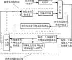
一般自动拉平控制结构如图2所示,要实现该控制结构,达到满意的控制效果,需要准确测量得到无人机的高度、升降速度、升降加速度、俯仰角和俯仰角速率,这种控制结构通常适用于传感器配置完备的大型无人机,不适用于简易传感器配置的小型无人机。其中,简易传感器配置是指配置的传感器只能满足基本测量需求,测量精度不高,也没有余度。The general automatic leveling control structure is shown in Figure 2. To realize the control structure and achieve a satisfactory control effect, it is necessary to accurately measure the height, lift speed, lift acceleration, pitch angle, and pitch angle rate of the UAV. This control structure It is usually suitable for large UAVs with complete sensor configurations, but not for small UAVs with simple sensor configurations. Among them, the simple sensor configuration means that the configured sensors can only meet the basic measurement requirements, the measurement accuracy is not high, and there is no margin.
常用的测量高度的传感器一般是大气机、无线电高度表、GPS等,这几种传感器的测量原理不同,各有其适用范围:大气机通过测量大气压力(常称静压)解算得到气压高度,但气压高度测量精度不是很高,通常适用于机场附近的飞行,大气机还可测量升降速度和空速,但升降速度的测量精度也不高,不能满足自动拉平控制的要求;无线电高度表则通过测量电磁波反射地面的时间,并根据无线电传播速度解算得到高度和升降速度,这种方法测量的数据精度高,但只限于低高度使用,适用于起飞着陆过程;GPS测量的是地理高度,适用于执行任务时的巡航飞行使用,GPS也可测量得到升降速度,但其高度和升降速度精度也不能满足自动拉平控制的使用要求。常用的测量升降加速度的传感器一般是惯导、加速度计,测量俯仰角和俯仰角速率的装置一般是惯导、垂直陀螺、速率陀螺,或一些组合型的陀螺组件。Commonly used sensors for measuring altitude are generally atmospheric machines, radio altimeters, and GPS. , but the measurement accuracy of barometric altitude is not very high, and it is usually suitable for flying near the airport. The atmospheric plane can also measure the ascending and descending speed and airspeed, but the measuring accuracy of the ascending and descending speed is not high, which cannot meet the requirements of automatic leveling control; radio altimeter By measuring the time of electromagnetic wave reflection on the ground, and calculating the altitude and lifting speed according to the radio propagation speed, the data measured by this method has high accuracy, but it is only used at low altitudes and is suitable for take-off and landing processes; GPS measures geographical altitude , suitable for cruising flight when performing missions, and GPS can also measure the vertical speed, but the accuracy of its height and vertical speed cannot meet the requirements of automatic leveling control. Commonly used sensors for measuring vertical acceleration are generally inertial navigation and accelerometers, and devices for measuring pitch angle and pitch rate are generally inertial navigation, vertical gyroscope, rate gyroscope, or some combined gyroscope components.
对于简易传感器配置的小型无人机,为了降低成本,系统组成会比较简单,一般只配置满足基本测量需求的高度传感器、空速传感器、俯仰角和俯仰角速率传感器等,如大气机和陀螺组件,而不会配置专门用于自动起飞着陆控制的无线电高度表,更不会配置像惯导这样价格昂贵的设备,因此简易配置传感器的无人机不能提供满足一般自动拉平控制结构所需的升降速度信息和升降加速度信息,一般的自动拉平控制方法不适用于简易配置的小型无人机自动着陆。For small UAVs with simple sensor configurations, in order to reduce costs, the system composition will be relatively simple, generally only equipped with altitude sensors, airspeed sensors, pitch angle and pitch rate sensors that meet basic measurement requirements, such as atmospheric engines and gyro components , and will not be equipped with a radio altimeter specially used for automatic take-off and landing control, let alone expensive equipment such as inertial navigation, so the UAV with simple sensor configuration cannot provide the lifting required to meet the general automatic leveling control structure Velocity information and lifting acceleration information, the general automatic leveling control method is not suitable for automatic landing of small UAVs with simple configuration.
另外,考虑到在起飞和着陆阶段,无人机的速度比较小、高度比较低,气流的变化(主要是风)对无人机飞行的影响非常明显,且控制系统中传感器的误差是使得控制发生偏差的另一个重要原因,这些不确定因素的影响将会使得自动控制效果不是那么理想。In addition, considering that during the take-off and landing phases, the speed of the UAV is relatively small and the altitude is relatively low, the change of airflow (mainly wind) has a very obvious impact on the flight of the UAV, and the error of the sensor in the control system is to make the control Another important reason for the deviation, the influence of these uncertain factors will make the effect of automatic control not so ideal.
一般具有自动控制功能的无人机,当自动控制系统出现某些问题时,操纵手可利用遥控操纵杆,通过无线数据链将遥控控制指令发送给飞机,从而实现对飞机的遥控操纵。一般的遥控操纵通常有四个操纵杆量:升降舵操纵杆量、方向舵操纵杆量、副翼操纵杆量和节风门操纵杆量,分别对应升降舵控制指令、方向舵控制指令、副翼控制指令和节风门控制指令。这里,可以利用升降舵操纵杆量和节风门操纵杆量对控制目标值的修正,实现对自动控制效果的修正,使得最终的控制效果更为精确,使这种简易传感器配置下的自动拉平控制方法能够适应不确定因素的影响,具有更强的抗干扰性,提高着陆的安全性。Generally, for UAVs with automatic control function, when some problems occur in the automatic control system, the operator can use the remote control joystick to send remote control instructions to the aircraft through the wireless data link, so as to realize the remote control of the aircraft. General remote control usually has four joystick values: elevator joystick amount, rudder joystick amount, aileron joystick amount and throttle joystick amount, corresponding to elevator control command, rudder control command, aileron control command and throttle respectively. Damper control command. Here, the correction of the control target value by the amount of the elevator joystick and the throttle joystick can be used to realize the correction of the automatic control effect, so that the final control effect is more accurate, and the automatic leveling control method under this simple sensor configuration It can adapt to the influence of uncertain factors, has stronger anti-interference performance, and improves the safety of landing.
发明内容Contents of the invention
本发明的目的是提出一种小型无人机自动着陆拉平控制方法及其装置,利用该控制方法及其控制装置,能够使具有简易传感器配置的小型无人机在进行轮式滑跑回收过程中具有很好的纵向着陆精度和适应能力,提高无人机的着陆安全性。The purpose of the present invention is to propose a small unmanned aerial vehicle automatic landing and leveling control method and its device. By using the control method and its control device, the small unmanned aerial vehicle with simple sensor configuration can be used in the recovery process of wheel sliding It has good vertical landing accuracy and adaptability, which improves the landing safety of UAVs.
为了达到上述目的,本发明利用简易传感器配置小型无人机的飞行高度、俯仰角、俯仰角速率以及空速信息,分别对无人机的俯仰角、空速进行控制,同时采集遥控操纵杆的升降舵操纵杆量和节风门操纵杆量分别对俯仰角和空速进行修正,最终实现无人机的自动拉平控制。本发明将自动着陆拉平控制装置分为俯仰角控制回路和空速控制回路两个控制模块,其中俯仰角控制回路由俯仰角和俯仰角速率传感器、高度传感器、期望俯仰角计算单元、期望俯仰角修正单元、俯仰角控制单元、升降舵组成;空速控制回路由空速传感器、高度传感器、期望空速计算单元、期望空速修正单元、空速控制单元、发动机组成。实现小型无人机的自动拉平控制具体包括以下六个步骤:In order to achieve the above object, the present invention uses simple sensors to configure the flight height, pitch angle, pitch angle rate and airspeed information of the small unmanned aerial vehicle, respectively controls the pitch angle and airspeed of the unmanned aerial vehicle, and collects the information of the remote control joystick at the same time. The amount of the elevator joystick and the throttle joystick correct the pitch angle and airspeed respectively, and finally realize the automatic leveling control of the UAV. In the present invention, the automatic landing leveling control device is divided into two control modules, a pitch angle control loop and an airspeed control loop, wherein the pitch angle control loop is composed of a pitch angle and a pitch angle rate sensor, a height sensor, a desired pitch angle calculation unit, a desired pitch angle The correction unit, the pitch angle control unit, and the elevator are composed; the airspeed control loop is composed of an airspeed sensor, an altitude sensor, a desired airspeed calculation unit, a desired airspeed correction unit, an airspeed control unit, and an engine. Realizing the automatic leveling control of small UAVs specifically includes the following six steps:
步骤一:实现期望俯仰角计算环节,得到期望俯仰角
根据无人机的飞行高度h(t)、开始拉平时的期望俯仰角


步骤二:实现期望俯仰角修正环节,得到含有俯仰角修正量

1)根据俯仰角修正上下边界值


2)根据俯仰角修正系数


3)根据期望俯仰角计算含有修正量


步骤三:实现俯仰角控制环节,得到升降舵控制指令δz(t);Step 3: Realize the pitch angle control link, and obtain the elevator control command δz (t);
根据无人机的俯仰角


步骤四:实现期望空速计算环节,得到期望空速vg(t);Step 4: Realize the link of calculating the desired airspeed, and obtain the desired airspeed vg (t);
根据无人机的飞行高度h(t)、开始拉平时的期望空速vgF、接地时的期望空速vgL、开始拉平时的高度hF、接地高度hL,得到拉平过程中飞行高度h(t)对应的期望空速vg(t),如式(6)所示:According to the flying height h(t) of the UAV, the expected airspeed vgF at the beginning of the leveling, the expected airspeed vgL at the touchdown, the height hF at the beginning of the leveling, and the height hL at the touchdown, the flight height during the leveling out process is obtained The desired airspeed vg (t) corresponding to h(t) is shown in formula (6):
步骤五:实现期望空速修正环节,得到含有空速修正量的期望空速v'ksemt(t);Step 5: Realize the expected airspeed correction link, and obtain the expected airspeed v'ksemt (t) including the airspeed correction amount;
1)根据空速修正上下边界值vkup和vkdw、节风门操纵杆量上下边界值δpup和δpdw,得到空速修正系数Kvx,如式(7)所示:1) Correct the upper and lower boundary values vkup and vkdw , and the upper and lower boundary values δpup and δpdw of the throttle control lever according to the airspeed to obtain the airspeed correction coefficient Kvx , as shown in formula (7):
2)根据空速修正系数Kvx和节风门操纵杆量δpro(t),得到空速修正量vgsemi(t),如式(8)所示:2) According to the airspeed correction coefficient Kvx and the throttle control lever amount δpro (t), the airspeed correction value vgsemi (t) is obtained, as shown in formula (8):
vgsemi(t)=Kvxδppro(t) (8)vgsemi (t)=Kvx δppro (t) (8)
3)根据期望空速vg(t),计算含有修正量的期望空速vg'(t),如式(9)所示:3) According to the desired airspeed vg (t), calculate the desired airspeed vg '(t) including the correction amount, as shown in formula (9):
vg'(t)=vgsemi(t)+vg(t) (9)vg '(t)=vgsemi (t)+vg (t) (9)
步骤六:实现空速控制,得到节风门控制指令δp(t);Step 6: Realize the airspeed control, and get the throttle control instruction δp (t);
根据无人机的空速vk(t)、含有修正的期望空速vg'(t)以及相应的控制参数Kp、KpI,得到节风门控制指令δp(t),如式(10)所示:According to the airspeed vk (t) of the UAV, the expected airspeed vg '(t) with correction and the corresponding control parameters Kp and KpI , the throttle control command δp (t) is obtained, as shown in the formula ( 10) as shown:
本发明提出的小型无人机自动着陆拉平控制方法及其装置的优点在于:The advantages of the small unmanned aerial vehicle automatic landing leveling control method and device thereof proposed by the present invention are:
(1)适用于小型无人机自动着陆拉平控制,尤其适用于简易传感器配置的小型无人机,能够达到较高的纵向着陆精度要求,具有良好的控制效果;(1) It is suitable for automatic landing and leveling control of small UAVs, especially for small UAVs with simple sensor configurations, which can meet high longitudinal landing accuracy requirements and have good control effects;
(2)遥控操纵人员可分别通过升降舵操纵杆和节风门操纵杆对俯仰角和空速控制进行修正,为遥控操纵手干预自动拉平控制提供了通道,能够提高飞机的抗干扰能力,达到适应多变情况的控制效果,有效提高着陆安全性;(2) The remote operator can modify the pitch angle and airspeed control through the elevator joystick and throttle joystick respectively, which provides a channel for the remote operator to intervene in the automatic leveling control, which can improve the anti-interference ability of the aircraft and achieve the goal of adapting to multiple The control effect of changing situations can effectively improve the safety of landing;
(3)利用本发明提出的期望俯仰角和期望空速的计算方法,可使无人机能够实现缓慢拉平的目的,尤其在低高度时,能够达到理想的接地速度和合适的俯仰角,有利于飞机的安全着陆。(3) Utilize the calculation method of expected pitch angle and expected airspeed proposed by the present invention, can make unmanned aerial vehicle realize the purpose of leveling off slowly, especially at low altitude, can reach ideal grounding speed and suitable pitch angle, have Conducive to the safe landing of the aircraft.
附图说明Description of drawings
图1是通常无人机整个着陆过程示意图;Figure 1 is a schematic diagram of the entire landing process of a common UAV;
图2是通常的无人机自动着陆拉平控制结构示意图;Fig. 2 is a schematic diagram of a common unmanned aerial vehicle automatic landing leveling control structure;
图3是本发明中小型无人机自动着陆拉平控制结构示意图;Fig. 3 is a schematic diagram of the automatic landing leveling control structure of small and medium-sized UAVs in the present invention;
图4是某无人机自动着陆拉平控制飞行高度仿真曲线图;Fig. 4 is a simulation curve diagram of a drone's automatic landing leveling control flight height;
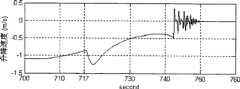
图5是某无人机自动着陆拉平控制升降速度仿真曲线图;Fig. 5 is a simulation curve diagram of automatic landing leveling control lifting speed of a certain UAV;
图6是某无人机自动着陆拉平控制俯仰角仿真曲线图;Fig. 6 is a simulation curve diagram of a UAV automatic landing leveling control pitch angle;
图7是某无人机自动着陆拉平控制空速仿真曲线图。Fig. 7 is a simulation curve diagram of an automatic landing leveling control airspeed of an unmanned aerial vehicle.
具体实施方式Detailed ways
下面结合附图和实例对本发明的无人机自动着陆拉平控制方法作进一步说明。The UAV automatic landing leveling control method of the present invention will be further described below in conjunction with the accompanying drawings and examples.
如图3所示,本发明提供的小型无人机自动着陆拉平控制方法中所设计的控制装置由俯仰角控制回路1、空速控制回路2两个控制模块组成。As shown in FIG. 3 , the control device designed in the control method for automatic landing and leveling of a small UAV provided by the present invention is composed of two control modules, a pitch
其中,俯仰角控制回路1由俯仰角及俯仰角速率传感器101、高度传感器102、期望俯仰角计算单元103、期望俯仰角修正单元104、俯仰角控制单元105及升降舵106组成。期望俯仰角计算单元103根据高度传感器102采集的无人机3的高度信息计算得到期望俯仰角


空速控制回路2由空速传感器201、高度传感器102、期望空速计算单元202、期望空速修正单元203、空速控制单元204、发动机205组成,期望空速计算单元202根据高度传感器102采集的无人机3的高度信息计算得到期望空速vg(t),该期望空速vg(t)与节风门操纵杆量δppro(t)对应的空速修正量vgsemi(t)一起送至期望空速修正单元203,得到含有修正量的期望空速通过空速传感器201采集得到的无人机3的空速信息与含有修正量的期望空速
本发明还提供一种小型无人机自动着陆拉平控制方法,具体通过以下步骤实现:The present invention also provides a control method for automatic landing and leveling of a small unmanned aerial vehicle, which is specifically realized through the following steps:
步骤一:实现期望俯仰角计算环节,得到期望俯仰角
飞机在垂直平面内,从下滑过渡到实际着陆点的纵向运动轨迹称之为拉平轨迹,拉平轨迹的设计,是使得飞机的升降速度
式中,hg(t)为期望高度,l(t)为拉平距离,hF为拉平开始时的高度,τ为指数曲线时间常数。In the formula, hg (t) is the expected height, l(t) is the leveling distance, hF is the height at the beginning of leveling, and τ is the time constant of the exponential curve.
由于机上测距装置测出的拉平距离l(t)的精度不能满足自动拉平控制的要求,因此,一般采用式(12)所示的规律:Since the accuracy of the leveling distance l(t) measured by the on-board ranging device cannot meet the requirements of automatic leveling control, the rule shown in formula (12) is generally adopted:
式中,

由飞机开始拉平时的高度hF和升降速度
因此,拉平过程中期望的升降速度
式(14)所表示的意义,是将整个拉平的过程看作飞机的升降速度不断跟踪期望升降速度的过程,要实现这个设计思想,需要获得精度足够高的升降速度信息,通常使用的是无线电高度表测量得到的升降速度信息,但是对于简易传感器配置的无人机,其配置的升降速度传感器通常是大气机,大气机所测量的升降速度信息的精度不能满足自动拉平控制的要求。现在,必须在可用的信息基础上寻找办法。The meaning expressed by Equation (14) is to regard the entire leveling process as a process in which the aircraft’s ascent and descent speed continuously tracks the desired ascent and descent speed. To realize this design idea, it is necessary to obtain sufficiently high-precision ascent and descent speed information, usually using radio The vertical speed information measured by the altimeter, but for UAVs with simple sensor configurations, the vertical speed sensor is usually an atmospheric machine, and the accuracy of the vertical speed information measured by the atmospheric machine cannot meet the requirements of automatic leveling control. Now, a solution must be found based on the information available.
在整个拉平过程中,最终控制的效果,是要使得飞机的升降速度慢慢减小,最终达到理想的接地速度,根据飞机飞行动力学理论,可知通过改变无人机的俯仰角,可以引起迎角的改变,进而引起升力的变化,则升降速度也发生变化,因此可以通过改变飞机的俯仰角来达到间接改变升降速度的目的。In the whole process of leveling out, the effect of the final control is to make the aircraft’s ascent and descent speed gradually decrease, and finally reach the ideal grounding speed. The change of the angle, and then the change of the lift, will also change the vertical speed, so the purpose of indirectly changing the vertical speed can be achieved by changing the pitch angle of the aircraft.
另外,通常自动控制方法的设计,都是针对无人机的质心的受力进行的,在实际的着陆控制过程中,轮式起降的无人机在地面滑跑时其质心距离地面有一定的高度,即接地时的高度hL,而并不是0,要获得更为精确的控制效果,应该在飞行高度h(t)中减去hL。如果忽略起落架在滑跑过程中的压缩变形量与飞机停在地面时的压缩变形量之间的微小差别,那么可用认为hL即是飞机停在地面时质心距离地面的高度。In addition, the design of the automatic control method is usually carried out for the force of the center of mass of the UAV. In the actual landing control process, the center of mass of the wheeled UAV is a certain distance from the ground when the UAV is sliding on the ground. The altitude of , that is, the altitude hL at touchdown, is not 0. To obtain a more precise control effect, hL should be subtracted from the flight altitude h(t). If the small difference between the compression deformation of the landing gear during the taxiing process and the compression deformation of the aircraft when it is parked on the ground is ignored, then hL can be considered as the height of the center of mass of the aircraft from the ground when the aircraft is parked on the ground.
根据无人机的飞行高度h(t)、开始拉平时的期望俯仰角接地时的期望俯仰角


设计俯仰角控制环节的过程中,可以根据无人机的气动数据建立相应的全量数学模型,并依据小扰动线性化方法得到相应的线性化方程,利用控制理论中的经典控制方法选取

步骤二:实现期望俯仰角修正环节,得到含有俯仰角修正量

1)根据俯仰角修正上下边界值和


在设计过程中,根据前述设计俯仰角控制环节时的方法选取并确定

通常,升降舵操纵杆量下边界值δzdw=0,升降舵操纵杆量上边界值δzup则由升降舵操纵杆的模数转换位数n决定,δzup=2n-1,n一般为8~12之间的正整数。例如,通常的遥控操纵杆的模数转换位n为8,则δzup=255。Usually, the lower boundary value of the elevator control stick δzdw = 0, and the upper limit value δzup of the elevator control stick is determined by the analog-to-digital conversion bit n of the elevator control stick, δzup = 2n -1, n is generally 8 ~ A positive integer between 12. For example, if the analog-to-digital conversion bit n of a common remote control joystick is 8, then δzup =255.
2)根据俯仰角修正系数

3)根据期望俯仰角


步骤三:实现俯仰角控制环节,得到升降舵控制指令δz(t);Step 3: Realize the pitch angle control link, and obtain the elevator control command δz (t);
根据无人机的俯仰角


控制参数
步骤四:实现期望空速计算环节,得到期望空速vg(t);Step 4: Realize the link of calculating the desired airspeed, and obtain the desired airspeed vg (t);
根据无人机的飞行高度、开始拉平时的期望空速vgF、接地时的期望空速vgL、开始拉平时的高度hF、接地时的高度hL,得到拉平过程中飞行高度h(t)对应的期望空速vg(t),如式(6)所示:According to the flight altitude of the UAV, the expected airspeed vgF at the start of leveling, the expected airspeed vgL at the time of touchdown, the height hF at the start of leveling out, and the height hL at the time of touchdown, the flight height h( t) corresponding to the desired airspeed vg (t), as shown in formula (6):
空速控制环节的设计,与前述俯仰角控制环节的设计过程相同,可以根据无人机的气动数据建立相应的全量数学模型,并依据小扰动线性化方法得到相应的线性化方程,利用控制理论中的经典控制方法选取vgF、vgL,然后利用无人机全量数学模型验证所设计的控制结构和参数是否能够使得系统满足控制要求。The design process of the airspeed control link is the same as the design process of the aforementioned pitch angle control link. The corresponding full-quantity mathematical model can be established according to the aerodynamic data of the UAV, and the corresponding linearization equation can be obtained according to the small disturbance linearization method. Using the control theory The classic control method in the paper selects vgF and vgL , and then uses the full mathematical model of the UAV to verify whether the designed control structure and parameters can make the system meet the control requirements.
步骤五:实现期望空速修正环节,得到含有空速修正量的期望空速;Step 5: Realize the expected airspeed correction link, and obtain the expected airspeed including the airspeed correction amount;
1)根据空速修正上下边界值vkup和vkdw、节风门操纵杆量上下边界值δpup δpdw,得到空速修正系数Kvx,如式(7)所示:1) Correct the upper and lower boundary values vkup and vkdw and the upper and lower boundary values of the throttle control lever δpup δpdw according to the airspeed to obtain the airspeed correction coefficient Kvx , as shown in formula (7):
其中,vkup、vkdw在前述的空速控制环节设计的过程中选取并确定。Among them, vkup and vkdw are selected and determined in the process of designing the aforementioned airspeed control link.
通常,节风门操纵杆量下边界值δpdw=O,节风门操纵量上边界值δpup则由节风门操纵杆的模数转换位数m决定,即δpup=2m-1,m一般为8~12之间的正整数。例如,通常的遥控操纵杆的模数转换位m为8,则δpup=255。Usually, the lower boundary value of the throttle control lever δpdw = 0, the upper boundary value of the throttle control variable δpup is determined by the analog-to-digital conversion digit m of the throttle control lever, that is, δpup = 2m -1, m is generally It is a positive integer between 8 and 12. For example, if the analog-to-digital conversion bit m of a common remote control joystick is 8, then δpup =255.
2)根据空速修正系数Kvx和节风门操纵杆量δppro(t),得到空速修正量vgsemi(t),如式(8)所示:2) According to the airspeed correction coefficient Kvx and the throttle control lever δppro (t), the airspeed correction vgsemi (t) is obtained, as shown in formula (8):
vgsemi(t)=Kvxδppro(t) (8)vgsemi (t)=Kvx δppro (t) (8)
3)根据期望空速vg(t),计算含有修正量的期望空速vg'(t),如式(9)所示:3) According to the desired airspeed vg (t), calculate the desired airspeed vg '(t) including the correction amount, as shown in formula (9):
vg'(t)=vgsemi(t)+vg(t) (9)vg '(t)=vgsemi (t)+vg (t) (9)
步骤六:实现空速控制环节,得到节风门控制指令δp(t);Step 6: Realize the airspeed control link, and obtain the throttle control command δp (t);
根据无人机的空速vk(t)、含有修正的期望空速vg'(t)以及相应的控制参数Kp、KpI,得到节风门控制指令,如式(10)所示:According to the airspeed vk (t) of the UAV, the expected airspeed vg '(t) with correction and the corresponding control parameters Kp and KpI , the throttle control command is obtained, as shown in formula (10):
其中,控制参数Kp、KpI是根据前述设计空速控制环节时的方法选取并确定。Among them, the control parameters Kp and KpI are selected and determined according to the aforementioned method for designing the airspeed control link.
本发明提供的小型无人机自动着陆拉平控制方法及其装置,将其应用于某无人机的自动着陆过程控制,该无人机为小型轮式起降型无人机,安装了大气机和陀螺组件,以获得高度、空速、俯仰角、俯仰角速率等满足基本控制需要的传感器信息,该无人机的拉平过程采用了本发明提供的自动拉平控制方法及其控制装置,实现了自动拉平控制,达到了满意的效果,提高了飞机着陆的安全性。The method and device for automatic landing and leveling control of a small unmanned aerial vehicle provided by the present invention are applied to the automatic landing process control of a certain unmanned aerial vehicle. and gyro components to obtain sensor information that meets the basic control needs such as altitude, airspeed, pitch angle, and pitch rate. The leveling process of the UAV adopts the automatic leveling control method and its control device provided by the present invention. The automatic leveling control has achieved a satisfactory effect and improved the safety of the aircraft landing.
图4、图5、图6、图7分别为该无人机自动着陆拉平控制飞行高度、升降速度、俯仰角及空速的仿真曲线图。该无人机的开始拉平时的高度hF=17m,开始拉平的期望俯仰角


本发明所述的小型无人机自动着陆拉平控制方法及其装置,充分利用简易传感器配置下小型无人机的俯仰角、俯仰角速率、空速、高度等信息,采用俯仰角控制与空速控制结合的方法,实现了自动拉平控制的目的;同时,本发明提出的期望俯仰角和期望空速的计算方法,使得在缺少高精度的升降速度信息的情况下,同样能够满足无人机拉平过程空速、升降速度缓慢减小并安全接地的要求,提高着陆的安全性。另外,通过将升降舵操纵杆量和节风门操纵杆量分别引入到期望俯仰角和期望空速的计算中,使得遥控操纵手能够根据需要,通过操纵遥控操纵杆对自动拉平控制的效果进行修正,提高了应对异常情况的处理能力,能够提高无人机着陆的可靠性,使无人机更能适应多变的情况。The small UAV automatic landing leveling control method and its device described in the present invention make full use of the pitch angle, pitch angle rate, airspeed, height and other information of the small UAV under the simple sensor configuration, and adopt the pitch angle control and airspeed The method of control combination realizes the purpose of automatic leveling control; at the same time, the calculation method of the expected pitch angle and expected airspeed proposed by the present invention makes it possible to meet the leveling requirements of the UAV in the absence of high-precision lifting speed information. The process airspeed, lift speed slowly decrease and the requirement of safe grounding improves the safety of landing. In addition, by introducing the amount of the elevator joystick and the throttle joystick into the calculation of the desired pitch angle and desired airspeed respectively, the remote pilot can correct the effect of the automatic leveling control by manipulating the remote joystick as needed, The ability to deal with abnormal situations is improved, which can improve the reliability of drone landing and make drones more adaptable to changing situations.
Claims (2)


Priority Applications (1)
| Application Number | Priority Date | Filing Date | Title |
|---|---|---|---|
| CN2008102411737ACN101441478B (en) | 2008-12-26 | 2008-12-26 | Small-sized unmanned aerial vehicle automatic landing leveling control method and apparatus |
Applications Claiming Priority (1)
| Application Number | Priority Date | Filing Date | Title |
|---|---|---|---|
| CN2008102411737ACN101441478B (en) | 2008-12-26 | 2008-12-26 | Small-sized unmanned aerial vehicle automatic landing leveling control method and apparatus |
Publications (2)
| Publication Number | Publication Date |
|---|---|
| CN101441478Atrue CN101441478A (en) | 2009-05-27 |
| CN101441478B CN101441478B (en) | 2011-02-02 |
Family
ID=40725940
Family Applications (1)
| Application Number | Title | Priority Date | Filing Date |
|---|---|---|---|
| CN2008102411737AExpired - Fee RelatedCN101441478B (en) | 2008-12-26 | 2008-12-26 | Small-sized unmanned aerial vehicle automatic landing leveling control method and apparatus |
Country Status (1)
| Country | Link |
|---|---|
| CN (1) | CN101441478B (en) |
Cited By (21)
| Publication number | Priority date | Publication date | Assignee | Title |
|---|---|---|---|---|
| CN102190081A (en)* | 2010-03-04 | 2011-09-21 | 南京航空航天大学 | Vision-based fixed point robust control method for airship |
| CN102289207A (en)* | 2011-06-08 | 2011-12-21 | 北京航空航天大学 | Macro instruction generator for unmanned aerial vehicle with variable flying mode and instruction generation method for macro instruction generator |
| CN102390543A (en)* | 2011-08-23 | 2012-03-28 | 北京航空航天大学 | Vertical landing track design method for unmanned aerial vehicle |
| CN103064421A (en)* | 2011-10-24 | 2013-04-24 | 空中客车运营简化股份公司 | Automatic landing method and device for aircraft on strong slope runway |
| CN103403638A (en)* | 2011-01-24 | 2013-11-20 | Abb公司 | Method for analyzing and diagnosing large scale process automation control systems |
| CN104391507A (en)* | 2014-10-09 | 2015-03-04 | 清华大学 | Control method and system of unmanned aerial vehicle, and unmanned aerial vehicle |
| CN104713545A (en)* | 2015-02-12 | 2015-06-17 | 中国科学院长春光学精密机械与物理研究所 | Theoretical trajectory guidance pattern-based single-pole compensation method |
| CN106672216A (en)* | 2016-12-13 | 2017-05-17 | 深圳市元征科技股份有限公司 | Method for controlling landing of unmanned aerial vehicle and unmanned aerial vehicle |
| CN107728634A (en)* | 2017-10-30 | 2018-02-23 | 刘先涛 | For controlling the flight control method and system of aircraft landing |
| CN108089597A (en)* | 2017-12-29 | 2018-05-29 | 易瓦特科技股份公司 | The method and device controlled based on earth station unmanned plane |
| CN109752955A (en)* | 2018-12-18 | 2019-05-14 | 南京航空航天大学 | Aircraft trajectory tracking and anti-disturbance control system and method based on two-dimensional position guidance |
| CN110262558A (en)* | 2019-07-18 | 2019-09-20 | 成都飞机工业(集团)有限责任公司 | A kind of control method of unmanned plane accuracy |
| CN110347177A (en)* | 2019-06-20 | 2019-10-18 | 沈阳无距科技有限公司 | Unmanned plane is grounded judgment method, device, storage medium and unmanned plane |
| CN110362108A (en)* | 2019-06-17 | 2019-10-22 | 沈阳无距科技有限公司 | Unmanned plane is grounded control method, device, storage medium and electronic equipment |
| CN111460650A (en)* | 2020-03-31 | 2020-07-28 | 北京航空航天大学 | An end-to-end control method for drones based on deep reinforcement learning |
| CN111813086A (en)* | 2020-07-15 | 2020-10-23 | 北京航空航天大学云南创新研究院 | A Model-Based Approach to Autonomy Evaluation of Unmanned Systems |
| CN112180980A (en)* | 2020-10-16 | 2021-01-05 | 中国直升机设计研究所 | Autorotation landing control method of unmanned helicopter |
| CN112433533A (en)* | 2020-10-29 | 2021-03-02 | 彩虹无人机科技有限公司 | Automatic landing control method for large-glide-ratio unmanned aerial vehicle |
| CN113093774A (en)* | 2019-12-23 | 2021-07-09 | 海鹰航空通用装备有限责任公司 | Unmanned aerial vehicle sliding control method |
| CN113190023A (en)* | 2021-03-31 | 2021-07-30 | 成都飞机工业(集团)有限责任公司 | Control method for full-autonomous arresting landing of carrier-borne unmanned aerial vehicle |
| CN113895645A (en)* | 2021-12-09 | 2022-01-07 | 四川腾盾科技有限公司 | Propeller unmanned aerial vehicle autonomous takeoff obstacle crossing capability analysis method |
Family Cites Families (3)
| Publication number | Priority date | Publication date | Assignee | Title |
|---|---|---|---|---|
| US6676088B1 (en)* | 2002-10-07 | 2004-01-13 | Safe Flight Instrument Corporation | Flare control system |
| FR2885439B1 (en)* | 2005-05-09 | 2010-11-19 | Airbus France | METHOD AND DEVICE FOR AIDING THE CONTROL OF AN AIRCRAFT DURING AN APPROACH PHASE FOR LANDING |
| CN101718994B (en)* | 2009-11-12 | 2011-02-16 | 北京航空航天大学 | Method for controlling automatic landing and leveling of unmanned aerial vehicle |
- 2008
- 2008-12-26CNCN2008102411737Apatent/CN101441478B/ennot_activeExpired - Fee Related
Cited By (31)
| Publication number | Priority date | Publication date | Assignee | Title |
|---|---|---|---|---|
| CN102190081A (en)* | 2010-03-04 | 2011-09-21 | 南京航空航天大学 | Vision-based fixed point robust control method for airship |
| CN102190081B (en)* | 2010-03-04 | 2013-09-04 | 南京航空航天大学 | Vision-based fixed point robust control method for airship |
| CN103403638A (en)* | 2011-01-24 | 2013-11-20 | Abb公司 | Method for analyzing and diagnosing large scale process automation control systems |
| CN103403638B (en)* | 2011-01-24 | 2016-12-21 | Abb公司 | For the method analyzing and diagnosing large scale process automation control system |
| CN102289207A (en)* | 2011-06-08 | 2011-12-21 | 北京航空航天大学 | Macro instruction generator for unmanned aerial vehicle with variable flying mode and instruction generation method for macro instruction generator |
| CN102390543A (en)* | 2011-08-23 | 2012-03-28 | 北京航空航天大学 | Vertical landing track design method for unmanned aerial vehicle |
| CN102390543B (en)* | 2011-08-23 | 2013-07-24 | 北京航空航天大学 | Vertical landing track design method for unmanned aerial vehicle |
| CN103064421A (en)* | 2011-10-24 | 2013-04-24 | 空中客车运营简化股份公司 | Automatic landing method and device for aircraft on strong slope runway |
| CN104391507A (en)* | 2014-10-09 | 2015-03-04 | 清华大学 | Control method and system of unmanned aerial vehicle, and unmanned aerial vehicle |
| CN104391507B (en)* | 2014-10-09 | 2017-04-19 | 深圳清华大学研究院 | Control method and system of unmanned aerial vehicle, and unmanned aerial vehicle |
| CN104713545A (en)* | 2015-02-12 | 2015-06-17 | 中国科学院长春光学精密机械与物理研究所 | Theoretical trajectory guidance pattern-based single-pole compensation method |
| WO2018107561A1 (en)* | 2016-12-13 | 2018-06-21 | 深圳市元征科技股份有限公司 | Method for controlling landing of unmanned aerial vehicle, and unmanned aerial vehicle |
| CN106672216A (en)* | 2016-12-13 | 2017-05-17 | 深圳市元征科技股份有限公司 | Method for controlling landing of unmanned aerial vehicle and unmanned aerial vehicle |
| CN107728634A (en)* | 2017-10-30 | 2018-02-23 | 刘先涛 | For controlling the flight control method and system of aircraft landing |
| CN108089597A (en)* | 2017-12-29 | 2018-05-29 | 易瓦特科技股份公司 | The method and device controlled based on earth station unmanned plane |
| CN109752955A (en)* | 2018-12-18 | 2019-05-14 | 南京航空航天大学 | Aircraft trajectory tracking and anti-disturbance control system and method based on two-dimensional position guidance |
| CN110362108A (en)* | 2019-06-17 | 2019-10-22 | 沈阳无距科技有限公司 | Unmanned plane is grounded control method, device, storage medium and electronic equipment |
| CN110362108B (en)* | 2019-06-17 | 2022-07-29 | 沈阳无距科技有限公司 | Unmanned aerial vehicle grounding control method and device, storage medium and electronic equipment |
| CN110347177A (en)* | 2019-06-20 | 2019-10-18 | 沈阳无距科技有限公司 | Unmanned plane is grounded judgment method, device, storage medium and unmanned plane |
| CN110262558A (en)* | 2019-07-18 | 2019-09-20 | 成都飞机工业(集团)有限责任公司 | A kind of control method of unmanned plane accuracy |
| CN113093774A (en)* | 2019-12-23 | 2021-07-09 | 海鹰航空通用装备有限责任公司 | Unmanned aerial vehicle sliding control method |
| CN111460650A (en)* | 2020-03-31 | 2020-07-28 | 北京航空航天大学 | An end-to-end control method for drones based on deep reinforcement learning |
| CN111813086A (en)* | 2020-07-15 | 2020-10-23 | 北京航空航天大学云南创新研究院 | A Model-Based Approach to Autonomy Evaluation of Unmanned Systems |
| CN111813086B (en)* | 2020-07-15 | 2023-08-25 | 北京航空航天大学云南创新研究院 | Model-based unmanned system autonomy assessment method |
| CN112180980A (en)* | 2020-10-16 | 2021-01-05 | 中国直升机设计研究所 | Autorotation landing control method of unmanned helicopter |
| CN112180980B (en)* | 2020-10-16 | 2022-10-28 | 中国直升机设计研究所 | Autorotation landing control method of unmanned helicopter |
| CN112433533A (en)* | 2020-10-29 | 2021-03-02 | 彩虹无人机科技有限公司 | Automatic landing control method for large-glide-ratio unmanned aerial vehicle |
| CN112433533B (en)* | 2020-10-29 | 2023-03-14 | 彩虹无人机科技有限公司 | Automatic landing control method for large-glide-ratio unmanned aerial vehicle |
| CN113190023A (en)* | 2021-03-31 | 2021-07-30 | 成都飞机工业(集团)有限责任公司 | Control method for full-autonomous arresting landing of carrier-borne unmanned aerial vehicle |
| CN113190023B (en)* | 2021-03-31 | 2022-05-10 | 成都飞机工业(集团)有限责任公司 | Control method for full-autonomous arresting landing of carrier-borne unmanned aerial vehicle |
| CN113895645A (en)* | 2021-12-09 | 2022-01-07 | 四川腾盾科技有限公司 | Propeller unmanned aerial vehicle autonomous takeoff obstacle crossing capability analysis method |
Also Published As
| Publication number | Publication date |
|---|---|
| CN101441478B (en) | 2011-02-02 |
Similar Documents
| Publication | Publication Date | Title |
|---|---|---|
| CN101441478B (en) | Small-sized unmanned aerial vehicle automatic landing leveling control method and apparatus | |
| CN102390543B (en) | Vertical landing track design method for unmanned aerial vehicle | |
| CN101718994B (en) | Method for controlling automatic landing and leveling of unmanned aerial vehicle | |
| CN110471450B (en) | A method for direct planning of reentry trajectories within an altitude velocity profile | |
| CN110928201B (en) | A semi-physical test method and system for aircraft avionics system | |
| CN112180968B (en) | Aircraft control method | |
| CN108873929B (en) | A method and system for autonomous landing of a fixed-wing aircraft | |
| US8793040B2 (en) | Climb-optimized auto takeoff system | |
| CN103587723B (en) | One reenters initial segment analytic expression longitudinally online Trajectory Design and tracking | |
| CN105468009B (en) | It is applied to many power fusion flight control system and the method for micro air vehicle | |
| CN108803639A (en) | A flight control method for quadrotor aircraft based on backstepping method | |
| CN102806990B (en) | Portable type mapping unmanned plane | |
| CN104590576A (en) | Flight control system and method for ship-borne unmanned aerial vehicle autonomous landing | |
| US10351230B2 (en) | Initial rotor state compensation for a rotorcraft | |
| CN101256412A (en) | An automatic homing control method for unmanned aerial vehicles when the engine stops unexpectedly | |
| CN109711008A (en) | A method for calculating the envelope of the center of gravity of an aircraft | |
| CN105045272A (en) | Automatic take-off control strategy design of small unmanned helicopter | |
| CN114721425B (en) | A method and control system for controlling the longitudinal trajectory of a UAV during collision with a rope | |
| CN114065398A (en) | Flight performance calculation method for high-aspect-ratio flexible aircraft | |
| CN106874617A (en) | A kind of efficient Helicopter Maneuver Flight quality grade appraisal procedure | |
| CN105242679A (en) | Method for designing control system of four rotor aircraft | |
| CN114912284B (en) | A first-principle based method for predicting the climb performance of a flight management system | |
| CN202345910U (en) | Fixed-height flight control system of fixed-wing unmanned aerial vehicle | |
| CN114942649A (en) | Airplane pitching attitude and track angle decoupling control method based on backstepping method | |
| JP5493103B2 (en) | Simple manual flight control system for unmanned flying vehicles |
Legal Events
| Date | Code | Title | Description |
|---|---|---|---|
| C06 | Publication | ||
| PB01 | Publication | ||
| C10 | Entry into substantive examination | ||
| SE01 | Entry into force of request for substantive examination | ||
| C53 | Correction of patent of invention or patent application | ||
| CB03 | Change of inventor or designer information | Inventor after:Wang Yingxun Inventor after:Wang Honglun Inventor after:Zhang Cuiping Inventor after:Wang Yong Inventor after:Fang Xiaoxing Inventor after:Shu Tingting Inventor before:Wang Yingxun Inventor before:Wang Honglun Inventor before:Zhang Cuiping Inventor before:Wang Yong Inventor before:Fang Xiaoxing | |
| COR | Change of bibliographic data | Free format text:CORRECT: INVENTOR; FROM: WANG YINGXUN WANG HONGLUN ZHANG CUIPING WANG YONG FANG XIAOXING TO: WANG YINGXUN WANG HONGLUN ZHANG CUIPING WANG YONG FANG XIAOXING SHU TINGTING | |
| C14 | Grant of patent or utility model | ||
| GR01 | Patent grant | ||
| C17 | Cessation of patent right | ||
| CF01 | Termination of patent right due to non-payment of annual fee | Granted publication date:20110202 Termination date:20121226 |