CN101437057B - Mobile communication device and its shell structure - Google Patents
Mobile communication device and its shell structureDownload PDFInfo
- Publication number
- CN101437057B CN101437057BCN200710186403XACN200710186403ACN101437057BCN 101437057 BCN101437057 BCN 101437057BCN 200710186403X ACN200710186403X ACN 200710186403XACN 200710186403 ACN200710186403 ACN 200710186403ACN 101437057 BCN101437057 BCN 101437057B
- Authority
- CN
- China
- Prior art keywords
- carbon fiber
- casing
- shell
- mentioned
- communication device
- Prior art date
- Legal status (The legal status is an assumption and is not a legal conclusion. Google has not performed a legal analysis and makes no representation as to the accuracy of the status listed.)
- Active
Links
- 238000010295mobile communicationMethods0.000titleclaimsabstractdescription56
- 229920000049Carbon (fiber)Polymers0.000claimsabstractdescription68
- 239000004917carbon fiberSubstances0.000claimsabstractdescription68
- VNWKTOKETHGBQD-UHFFFAOYSA-NmethaneChemical compoundCVNWKTOKETHGBQD-UHFFFAOYSA-N0.000claimsabstractdescription67
- 239000000835fiberSubstances0.000claimsabstractdescription51
- 238000004519manufacturing processMethods0.000claimsabstractdescription29
- 239000000463materialSubstances0.000claimsdescription25
- 239000004744fabricSubstances0.000claimsdescription15
- 239000002131composite materialSubstances0.000claimsdescription8
- 239000003365glass fiberSubstances0.000claimsdescription6
- 229920002239polyacrylonitrilePolymers0.000claimsdescription5
- ZOXJGFHDIHLPTG-UHFFFAOYSA-NBoronChemical compound[B]ZOXJGFHDIHLPTG-UHFFFAOYSA-N0.000claimsdescription4
- 229920000297RayonPolymers0.000claimsdescription4
- 229910052796boronInorganic materials0.000claimsdescription4
- 239000002964rayonSubstances0.000claimsdescription4
- HBMJWWWQQXIZIP-UHFFFAOYSA-Nsilicon carbideChemical compound[Si+]#[C-]HBMJWWWQQXIZIP-UHFFFAOYSA-N0.000claimsdescription4
- 229910010271silicon carbideInorganic materials0.000claimsdescription4
- 238000000465mouldingMethods0.000claims3
- 229920003023plasticPolymers0.000description12
- 239000004033plasticSubstances0.000description12
- 238000010586diagramMethods0.000description6
- 238000004891communicationMethods0.000description4
- 238000000034methodMethods0.000description4
- 239000000956alloySubstances0.000description3
- 229910045601alloyInorganic materials0.000description3
- 238000013461designMethods0.000description3
- 239000002184metalSubstances0.000description3
- 230000005540biological transmissionEffects0.000description1
- 239000000919ceramicSubstances0.000description1
- 230000008859changeEffects0.000description1
- 239000004020conductorSubstances0.000description1
- 230000007547defectEffects0.000description1
- 230000007812deficiencyEffects0.000description1
- 230000000694effectsEffects0.000description1
- 230000005611electricityEffects0.000description1
- 239000002657fibrous materialSubstances0.000description1
- 238000007731hot pressingMethods0.000description1
- 230000004048modificationEffects0.000description1
- 238000012986modificationMethods0.000description1
- 238000012545processingMethods0.000description1
- 229920005989resinPolymers0.000description1
- 239000011347resinSubstances0.000description1
- 238000002791soakingMethods0.000description1
- 238000009941weavingMethods0.000description1
Images


Landscapes
- Telephone Set Structure (AREA)
- Support Of Aerials (AREA)
Abstract
Description
Translated fromChinese技术领域technical field
本发明涉及一种电子装置、壳体结构及壳体结构的制造方法,特别是一种移动通讯装置、壳体结构及壳体结构的制造方法。The invention relates to an electronic device, a housing structure and a manufacturing method of the housing structure, in particular to a mobile communication device, a housing structure and a manufacturing method of the housing structure.
背景技术Background technique
近年来,各种移动式电子装置皆以轻薄短小为主要设计需求,而目前以具有通讯功能的移动式电子装置最为普遍。为使移动通讯装置轻量化,壳体材质的选择与设计为关键因素之一。在多种复合材质之中,因碳纤维材质具有高强度、重量轻等优点,故可作为移动通讯装置壳体的理想材质之一。In recent years, the main design requirements of various mobile electronic devices are light, thin and small, and currently mobile electronic devices with communication functions are the most common. In order to reduce the weight of the mobile communication device, the selection and design of the housing material is one of the key factors. Among various composite materials, the carbon fiber material can be used as one of the ideal materials for the casing of the mobile communication device due to its advantages of high strength and light weight.
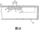
请参照图1A及图1B所示,现有技术的移动通讯装置1包含一第一壳体11、一第二壳体12、一天线13、一第三壳体15及一第四壳体16。移动通讯装置1是以一具有天线的笔记本电脑为例。第二壳体12与第一壳体11相互连结;第三壳体15与第四壳体16相互连结。为了减轻移动通讯装置1的重量,并同时兼具足够的壳体结构强度,第一壳体11与第三壳体15的大部分面积为碳纤维材质。另外,移动通讯装置1的第一壳体11及第二壳体12可与一显示模块14组成一显示单元1a;而第三壳部15、第四壳部16、一主机(图未显示)及一输入模块18(包含一键盘181及一触控板182)则组成一主机单元1b。显示单元1a与主机单元1b则通过一枢轴19连结。1A and 1B, the prior art
如图1B所示,天线13设置于第一壳体11与第二壳体12之间,且第一壳体11具有一碳纤维壳部111及一塑料壳部112,其中,碳纤维壳部111占第一壳体11的大部分,而塑料壳部112只设置于天线13对应于第一壳体11的地方。由于碳纤维壳部111的碳纤维材质为电的良导体,会影响电磁波的传送。为使天线13能够正常收发讯号,故于制作第一壳体11时,通常是先形成一个碳纤维材质的壳体,然后在对应天线13设置的地方,经由后制加工镂空或切除,以将塑料壳部112设置于天线13对应于第一壳体11的地方。如此一来,也增加了制程的成本。As shown in Figure 1B, the
另外,由于现有的塑料壳部112与碳纤维壳部111的材质差异性大,需要分别成形。因此要将塑料壳部112固定于碳纤维壳部111时,需通过固定件M及多个螺丝S的协助,才能使塑料壳部112与碳纤维壳部111锁固,故更增加了材料与组装的成本。再者,塑料壳部112组设于碳纤维壳部111时,易产生一段差H或者一间隙G,进而影响移动通讯装置1外观的平坦度。In addition, since the materials of the conventional
因此,如何提供一种移动通讯装置、壳体结构及壳体结构的制造方法以取代已知壳体结构的设计,以于外观上产生一致性,并可减低生产成本,已成为重要课题之一。Therefore, how to provide a mobile communication device, a housing structure and a manufacturing method of the housing structure to replace the design of the known housing structure, so as to produce consistency in appearance and reduce production costs has become one of the important issues .
发明内容Contents of the invention
有鉴于上述课题,本发明的目的在于克服现有技术的不足与缺陷,提出一种移动通讯装置、壳体结构及壳体结构的制造方法,可增加碳纤维壳体与天线区域的壳体间不同材质结合后的外观平坦度。In view of the above problems, the purpose of the present invention is to overcome the deficiencies and defects of the prior art, and propose a mobile communication device, a housing structure and a manufacturing method of the housing structure, which can increase the difference between the carbon fiber housing and the housing in the antenna area. Appearance flatness after materials are combined.
为达上述目的,依据本发明提供的一种移动通讯装置,包含一壳体结构以及一天线。壳体结构具有一碳纤维壳部及一非导电纤维壳部。天线设置于壳体结构内,天线的讯号收发位置对应于非导电纤维壳部。To achieve the above purpose, a mobile communication device according to the present invention includes a casing structure and an antenna. The shell structure has a carbon fiber shell and a non-conductive fiber shell. The antenna is arranged in the shell structure, and the signal sending and receiving position of the antenna corresponds to the non-conductive fiber shell.
为达上述目的,依据本发明提供的一种壳体结构,应用于一移动通讯装置,移动通讯装置具有一天线,壳体结构包含一碳纤维壳部及一非导电纤维壳部相互接合。其中,天线设置于壳体结构内,且天线的讯号收发位置对应于非导电纤维壳部。To achieve the above purpose, the present invention provides a shell structure applied to a mobile communication device, the mobile communication device has an antenna, and the shell structure includes a carbon fiber shell and a non-conductive fiber shell joined together. Wherein, the antenna is arranged in the casing structure, and the signal sending and receiving position of the antenna corresponds to the non-conductive fiber casing.
为达上述目的,依据本发明提供的一种壳体结构的制造方法,上述壳体结构应用于一移动通讯装置,上述移动通讯装置具有一天线,上述壳体结构的制造方法的特征在于,包含以下步骤:堆叠多层碳纤维布以形成一结构;形成一镂空处于上述结构,上述镂空处对应于上述天线的预定讯号收发位置;覆盖一非导电性纤维布于上述结构以遮蔽上述镂空处;以及施加一压力与一温度于上述结构。In order to achieve the above purpose, according to a manufacturing method of a housing structure provided by the present invention, the housing structure is applied to a mobile communication device, the mobile communication device has an antenna, and the manufacturing method of the housing structure is characterized in that it includes The following steps: stacking multiple layers of carbon fiber cloth to form a structure; forming a hollow in the structure, the hollow corresponding to the predetermined signal receiving and receiving position of the antenna; covering the structure with a non-conductive fiber cloth to cover the hollow; and Applying a pressure and a temperature to the structure.
承上所述,因依据本发明的一种移动通讯装置、壳体结构及壳体结构的制造方法,通过碳纤维壳部及对应天线设置的非导电纤维壳部一体成型制成。与现有技术相较,本发明的壳体结构以碳纤维材质与非导电纤维材质的结合,取代现有的塑料件,以增加移动通讯装置外观的一致性,并减轻壳体重量、薄化壳体体积及简化制程,进而减低生产成本。Based on the above, according to the mobile communication device, the shell structure and the manufacturing method of the shell structure of the present invention, the carbon fiber shell and the non-conductive fiber shell corresponding to the antenna are integrally formed. Compared with the prior art, the shell structure of the present invention uses a combination of carbon fiber material and non-conductive fiber material to replace the existing plastic parts, so as to increase the consistency of the appearance of the mobile communication device, reduce the weight of the shell, and thin the shell. Volume and simplify the manufacturing process, thereby reducing production costs.
附图说明Description of drawings
图1A为一种已知的移动通讯装置的示意图;FIG. 1A is a schematic diagram of a known mobile communication device;
图1B为图1A沿A-A’剖面线的示意图;Fig. 1B is a schematic diagram of Fig. 1A along the section line A-A';
图2为依据本发明第一实施例的移动通讯装置及其局部放大的示意图;2 is a schematic diagram of a mobile communication device and its partial enlargement according to the first embodiment of the present invention;
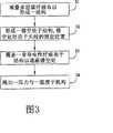
图3为依据本发明的移动通讯装置的壳体结构的制造方法的流程图;3 is a flowchart of a method for manufacturing a housing structure of a mobile communication device according to the present invention;
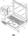
图4A为依据本发明第二实施例的移动通讯装置及其局部放大的示意图;4A is a schematic diagram of a mobile communication device and its partial enlargement according to a second embodiment of the present invention;
图4B为图4A的移动通讯装置盖合的示意图;FIG. 4B is a schematic diagram of the mobile communication device shown in FIG. 4A being covered;
图5为依据本发明第三实施例的移动通讯装置及其局部放大的示意图。FIG. 5 is a schematic diagram of a mobile communication device and its partial enlargement according to a third embodiment of the present invention.
具体实施方式Detailed ways
以下将参照相关附图,说明依据本发明较佳实施例的一种移动通讯装置、壳体结构及壳体结构的制造方法,其中相同的组件将以相同的符号加以说明。A mobile communication device, a housing structure and a manufacturing method of the housing structure according to preferred embodiments of the present invention will be described below with reference to related drawings, wherein the same components will be described with the same symbols.
第一实施例:First embodiment:
请参阅图2所示,本发明第一实施例的移动通讯装置2包含一壳体结构20以及一天线23。于本实施例中,移动通讯装置2可为任何具有天线的通讯装置,在此,以一个人数字助理(Personal Digital Assistant,PDA)为例来进行说明。Please refer to FIG. 2 , the mobile communication device 2 according to the first embodiment of the present invention includes a
壳体结构20包含一第一壳体21及一第二壳体22,第一壳体21连结于第二壳体22,连结的方式可例如为卡合、锁合或螺合等等。其中,第一壳体21的材质并不加以限定,可例如为碳纤维、塑料、金属或合金等等,第二壳体22具有一碳纤维壳部221及一非导电纤维壳部222。其中,碳纤维壳部221的材质为碳纤维复合材质,例如但不限为一聚丙烯腈系(polyacrylonitrile)的碳纤维、一沥青系的碳纤维、一嫘萦系的碳纤维或其组合,纤维的形型态可为长纤维或短纤维。另外,非导电纤维壳部222的材质可为玻璃纤维、硼纤维、碳化硅纤维或其组合。本实施例中,非导电纤维壳部222的材质较佳为一玻璃纤维。The
在本实施例中,移动通讯装置2更包含一显示模块24,设置于第一壳体21与第二壳体22之间,且第二壳体22具有一开口O,而显示模块24具有一显示面P由开口O露出。In this embodiment, the mobile communication device 2 further includes a
天线23以一陶瓷天线为例,天线33的类型及面积大小则可依实际产品需求来设计,天线23设置于第一壳体21及第二壳体22。通常,天线23设置于不会与显示模块24迭合的地方,例如显示模块24之外的空间,本实施例是以天线23设置于第二壳体22的周缘为例。其中,第二壳体22为移动通讯装置1的操作面,一般朝上使用,故天线23的电磁波需穿过第二壳体22以收发讯号。因此,第二壳部22的非导电纤维壳部222是对应天线23的讯号收发位置设置,以使天线23的讯号收发功能可正常运作。The
请参阅图3及配合参阅图2所示,本发明的移动通讯装置2的壳体结构20的制造方法包含步骤S1~S4。在步骤S1中,堆叠多层碳纤维布以形成一结构(例如为图2中的第一壳体21),其中碳纤维布是由碳纤维经纤维编织及树脂浸泡而形成,而堆叠的厚度愈大,则结构的强度也愈大。在步骤S2中,形成一镂空处于结构(例如第一壳体21),并使镂空处对应于天线23的预定位置。在步骤S3中,覆盖一非导电性纤维布于结构以遮蔽镂空处。在步骤S4中,将碳纤维布与非导电纤维布形成的结构一同入模后,施加一压力与一温度,亦即一热压处理,使碳纤维壳部221与非导电纤维壳部222一体成型。如此一来,即可获得外观上相当平坦的第一壳体21,而且也节省了制程及材料成本。需注意的是,碳纤维壳部221与非导电纤维壳部222的成型步骤,可能有所变化,例如也可以先将碳纤维壳部221先成型后,再成型非导电纤维壳部222。另外,非导电纤维壳部222所设置的面积大小、厚度及位置并不限制,可随产品实际需求而设计。Referring to FIG. 3 and FIG. 2 together, the manufacturing method of the
第二实施例:Second embodiment:
请同时参阅图4A及图4B所示,本发明第二实施例的一种移动通讯装置3,移动通讯装置3具有一天线33以及一壳体结构30,其中,壳体结构30包含一第一壳体31、一第二壳体32、一第三壳体35以及一第四壳体36。在本实施例中,移动通讯装置3以一具有通讯功能的笔记本电脑为例。Please refer to FIG. 4A and FIG. 4B at the same time, a mobile communication device 3 according to the second embodiment of the present invention, the mobile communication device 3 has an
本实施例中,移动通讯装置3更包含一显示模块34以及一主机37。显示模块34设置于第一壳体31与第二壳体32之间,第一壳体31与第二壳体32包覆显示模块34,第一壳体31具有一开口O,显示模块34的一显示面P由开口O露出。而主机37设置于第三壳体35及第四壳体36之间,使得第三壳体35及第四壳体36包覆主机37。其中,第一壳体31、第二壳体32及显示模块34形成一显示单元3a;而第三壳体33、第四壳体34及主机37形成一主机单元30b,主机单元3b通过一枢轴39与显示单元3a连结。另外,主机单元3b更具有一输入模块38,本实施例中以一键盘381(keyboard)及一触控板382(touch pad)为例。In this embodiment, the mobile communication device 3 further includes a
第一壳体31与第二壳体32连结,连结的方式可例如为卡合、锁合或螺合等等,其中第二壳体32具有一碳纤维壳部321及一非导电纤维壳部322。本实施例中,碳纤维壳部321及非导电纤维壳部322的构成材质及制作方式与上述第一实施例的碳纤维壳部221及非导电纤维壳部222相同,在此不再赘述。另外,因第三壳体35及第四壳体36并无天线设置,故第三壳体35的材质可为碳纤维材质构成,而第四壳体36则例如为碳纤维、塑料、金属或合金等等。The
天线33设置于第一壳体31及第二壳体32之间,天线33的类型及面积大小则可依实际产品需求来设计。在本实施例中,天线33设置于第二壳体32周缘,且非导电纤维壳部322与天线33的讯号收发位置对应设置,以利天线33收发讯号。此外,非导电纤维壳部322亦可选择对应天线33而设置于第二壳体32周缘的其它区域A,例如第二壳体32的二侧边,或是枢轴39的邻近区域。而且,非导电纤维壳部322所对应设置的面积可近似或大于天线33设置的面积(如图4B所示)以利收发数据讯号。需注意的是,为增强天线33的接收效果,第一壳体31亦可于对应天线33的地方设置非导电纤维壳部(图未显示)。The
第三实施例:Third embodiment:
请参阅图5所示,本发明第三实施例的一种移动通讯装置4,移动通讯装置4具有一天线43以及一壳体结构40。其中,壳体结构40包含一第一壳体41以及一第二壳体42、一第三壳体45以及一第四壳体46。在本实施例中,移动通讯装置4同样以一具有通讯功能的笔记本电脑为例说明。Please refer to FIG. 5 , which shows a mobile communication device 4 according to the third embodiment of the present invention. The mobile communication device 4 has an
移动通讯装置4更包含一主机47、一输入模块48以及一显示单元4a,而第一壳体41、第二壳体42、主机47以及输入模块48则可形成一主机单元4b。其中,第一壳体41及第二壳体42包覆主机47;输入模块48包含一键盘481及一触控板482,并设置于第一壳体41及第二壳体42之间。本实施例中的移动通讯装置4与第二实施例不同之处在于:移动通讯装置4的天线43设置于主机单元4b。另外,显示单元4a则具有第三壳体45、第四壳体46及一显示模块44,且第四壳体46具有一开口O,显示模块44的一显示面P由开口O露出。需注意的是,第三壳体45及第四壳体46并无天线设置,故第三壳体45的材质可为碳纤维材质构成,而第四壳体46则例如为碳纤维、塑料、金属或合金制成。The mobile communication device 4 further includes a
第二壳体42的碳纤维壳部421及非导电纤维壳部422的构成材质及制作方式与上述第二实施例的碳纤维壳部321及非导电纤维壳部322相同,在此不再赘述。The carbon
在本实施例中,天线43可选择设置于第二壳体42的周缘。同样地,使非导电纤维壳部422与天线43对应设置于第二壳体42的周缘并与碳纤维壳部421一体成型,不但可使天线43具有收发数据讯号的功能,更可提升移动通讯装置4的外观平坦度。In this embodiment, the
综上所述,因依据本发明的一种移动通讯装置、壳体结构及壳体结构的制造方法通过碳纤维壳部及对应天线设置的非导电纤维壳部以一体成型制成。与现有技术相较,本发明的壳体结以碳纤维材质与玻璃纤维材质的结合,取代现有的塑料件,以增加移动通讯装置外观的一致性,并减轻壳体重量、薄化壳体体积及简化制程,进而减低生产成本。To sum up, according to the mobile communication device, the housing structure and the manufacturing method of the housing structure according to the present invention, the carbon fiber shell and the non-conductive fiber shell corresponding to the antenna are integrally formed. Compared with the prior art, the casing of the present invention is made of a combination of carbon fiber material and glass fiber material to replace the existing plastic parts, so as to increase the consistency of the appearance of the mobile communication device, reduce the weight of the casing, and thinn the casing Smaller size and simplified manufacturing process, thereby reducing production cost.
以上所述仅为举例性,而非为限制性。任何未脱离本发明的精神与范畴,而对其进行的等效修改或变更,均应包含于本发明权利要求书的范围中。The above description is for illustration only, not for limitation. Any equivalent modification or change without departing from the spirit and scope of the present invention shall be included in the scope of the claims of the present invention.
Claims (16)
Translated fromChinesePriority Applications (1)
| Application Number | Priority Date | Filing Date | Title |
|---|---|---|---|
| CN200710186403XACN101437057B (en) | 2007-11-16 | 2007-11-16 | Mobile communication device and its shell structure |
Applications Claiming Priority (1)
| Application Number | Priority Date | Filing Date | Title |
|---|---|---|---|
| CN200710186403XACN101437057B (en) | 2007-11-16 | 2007-11-16 | Mobile communication device and its shell structure |
Publications (2)
| Publication Number | Publication Date |
|---|---|
| CN101437057A CN101437057A (en) | 2009-05-20 |
| CN101437057Btrue CN101437057B (en) | 2012-11-07 |
Family
ID=40711276
Family Applications (1)
| Application Number | Title | Priority Date | Filing Date |
|---|---|---|---|
| CN200710186403XAActiveCN101437057B (en) | 2007-11-16 | 2007-11-16 | Mobile communication device and its shell structure |
Country Status (1)
| Country | Link |
|---|---|
| CN (1) | CN101437057B (en) |
Families Citing this family (10)
| Publication number | Priority date | Publication date | Assignee | Title |
|---|---|---|---|---|
| US8618415B2 (en)* | 2010-10-22 | 2013-12-31 | Blackberry Limited | Portable electronic device and method of manufacturing parts thereof |
| DE112011105747T5 (en) | 2011-10-19 | 2014-09-25 | Hewlett-Packard Development Company, L.P. | Material with signal pass and signal blocking strands |
| JPWO2013136398A1 (en)* | 2012-03-12 | 2015-07-30 | 日本電気株式会社 | Mobile terminal device |
| CN103935045A (en)* | 2013-01-21 | 2014-07-23 | 汉达精密电子(昆山)有限公司 | Carbon fiber processing method and carbon fiber product |
| CN105556934A (en)* | 2013-09-24 | 2016-05-04 | 华为技术有限公司 | Shell component for electronic device, electronic device and method for manufacturing shell component |
| CN105965989B (en)* | 2016-05-06 | 2018-08-28 | 湖南东映碳材料科技有限公司 | A kind of preparation method of Carbon fibe reinforced resin composite material |
| CN106659015B (en)* | 2016-11-17 | 2022-05-24 | 广东创世纪智能装备集团股份有限公司 | Electronic product frame body integrally-formed structural part and manufacturing method thereof |
| CN115580671B (en)* | 2020-06-28 | 2023-07-14 | 华为技术有限公司 | Rotating shaft assembly and folding screen equipment |
| DE102020008085B4 (en) | 2020-07-11 | 2022-03-17 | Carbon Mobile GmbH | Molded part for a mobile end device with transmitter and/or receiver device made from carbon fiber reinforced plastic |
| DE102020118348B4 (en) | 2020-07-11 | 2025-04-30 | Carbon Mobile GmbH | Moulded part for a mobile terminal with transmitting and/or receiving device made of carbon fibre reinforced plastic |
Citations (4)
| Publication number | Priority date | Publication date | Assignee | Title |
|---|---|---|---|---|
| CN1363867A (en)* | 2001-01-10 | 2002-08-14 | 埔丰实业股份有限公司 | Reinforcement method of carbon fiber for aluminum-magnesium alloy shell of notebook computer |
| EP1245625A1 (en)* | 2001-03-28 | 2002-10-02 | Ube Industries, Ltd. | Conductive resin composition and process for producing the same |
| CN1441612A (en)* | 2001-11-07 | 2003-09-10 | 日本电气株式会社 | Radio terminal device |
| CN1915730A (en)* | 2005-08-19 | 2007-02-21 | 超胜贸易有限公司 | Method for combining holders of bicycle racks |
- 2007
- 2007-11-16CNCN200710186403XApatent/CN101437057B/enactiveActive
Patent Citations (4)
| Publication number | Priority date | Publication date | Assignee | Title |
|---|---|---|---|---|
| CN1363867A (en)* | 2001-01-10 | 2002-08-14 | 埔丰实业股份有限公司 | Reinforcement method of carbon fiber for aluminum-magnesium alloy shell of notebook computer |
| EP1245625A1 (en)* | 2001-03-28 | 2002-10-02 | Ube Industries, Ltd. | Conductive resin composition and process for producing the same |
| CN1441612A (en)* | 2001-11-07 | 2003-09-10 | 日本电气株式会社 | Radio terminal device |
| CN1915730A (en)* | 2005-08-19 | 2007-02-21 | 超胜贸易有限公司 | Method for combining holders of bicycle racks |
Also Published As
| Publication number | Publication date |
|---|---|
| CN101437057A (en) | 2009-05-20 |
Similar Documents
| Publication | Publication Date | Title |
|---|---|---|
| CN101437057B (en) | Mobile communication device and its shell structure | |
| US20090130995A1 (en) | Mobile communication device, housing structure and manufacturing method of housing structure | |
| JP5827278B2 (en) | Electronic device housing and processing method thereof | |
| US20100014235A1 (en) | Electronic device and keyboard module thereof | |
| CN105552526B (en) | Mobile terminal | |
| US9367155B2 (en) | Touch panel assembly and electronic device | |
| US9772717B2 (en) | Input sensor for an electronic device | |
| US11769940B2 (en) | Electronic device housing with integrated antenna | |
| CN202713411U (en) | A mobile phone side button antenna device | |
| CN101895011A (en) | Wideband printing antenna with symmetrical dipole-antipodal slot line composite structure | |
| KR20210014606A (en) | Rigid flexible printed circuit board and electronic device including the same | |
| CN107567225B (en) | Middle frame manufacturing method, middle frame, electronic equipment and middle frame base body | |
| KR20080113506A (en) | Touch panel device and manufacturing method thereof | |
| CN108107980B (en) | Electronic device | |
| CN117276859A (en) | Electronic equipment | |
| CN113423212B (en) | Electronic equipment, housing, diaphragm and manufacturing method thereof | |
| TW200821798A (en) | Touch panel module and method of fabricating the same | |
| US12185464B2 (en) | Rigid flexible printed circuit board and electronic device comprising same | |
| KR102850000B1 (en) | Mobile device, cover plate for the mobile device, and method of manufacturing the cover plate for the mobile device | |
| CN215121371U (en) | The housing structure of the hand-held device | |
| CN211808274U (en) | Composite board | |
| CN103249244A (en) | Flexible printed circuit board | |
| JP2017147537A (en) | Electronic apparatus and electronic apparatus enclosure | |
| CN103513809A (en) | FPC touch screen | |
| CN218100579U (en) | Display device and wearable product |
Legal Events
| Date | Code | Title | Description |
|---|---|---|---|
| C06 | Publication | ||
| PB01 | Publication | ||
| C10 | Entry into substantive examination | ||
| SE01 | Entry into force of request for substantive examination | ||
| C14 | Grant of patent or utility model | ||
| GR01 | Patent grant |