CN101432130B - Improvements to pressure pads - Google Patents
Improvements to pressure padsDownload PDFInfo
- Publication number
- CN101432130B CN101432130BCN2007800157631ACN200780015763ACN101432130BCN 101432130 BCN101432130 BCN 101432130BCN 2007800157631 ACN2007800157631 ACN 2007800157631ACN 200780015763 ACN200780015763 ACN 200780015763ACN 101432130 BCN101432130 BCN 101432130B
- Authority
- CN
- China
- Prior art keywords
- pressure pad
- strands
- core
- pressure
- sheath
- Prior art date
- Legal status (The legal status is an assumption and is not a legal conclusion. Google has not performed a legal analysis and makes no representation as to the accuracy of the status listed.)
- Active
Links
Images


Classifications
- B—PERFORMING OPERATIONS; TRANSPORTING
- B30—PRESSES
- B30B—PRESSES IN GENERAL
- B30B15/00—Details of, or accessories for, presses; Auxiliary measures in connection with pressing
- B30B15/06—Platens or press rams
- B30B15/061—Cushion plates
- B—PERFORMING OPERATIONS; TRANSPORTING
- B30—PRESSES
- B30B—PRESSES IN GENERAL
- B30B15/00—Details of, or accessories for, presses; Auxiliary measures in connection with pressing
- B30B15/06—Platens or press rams
- D—TEXTILES; PAPER
- D02—YARNS; MECHANICAL FINISHING OF YARNS OR ROPES; WARPING OR BEAMING
- D02G—CRIMPING OR CURLING FIBRES, FILAMENTS, THREADS, OR YARNS; YARNS OR THREADS
- D02G3/00—Yarns or threads, e.g. fancy yarns; Processes or apparatus for the production thereof, not otherwise provided for
- D02G3/02—Yarns or threads characterised by the material or by the materials from which they are made
- D02G3/12—Threads containing metallic filaments or strips
- D—TEXTILES; PAPER
- D02—YARNS; MECHANICAL FINISHING OF YARNS OR ROPES; WARPING OR BEAMING
- D02G—CRIMPING OR CURLING FIBRES, FILAMENTS, THREADS, OR YARNS; YARNS OR THREADS
- D02G3/00—Yarns or threads, e.g. fancy yarns; Processes or apparatus for the production thereof, not otherwise provided for
- D02G3/22—Yarns or threads characterised by constructional features, e.g. blending, filament/fibre
- D02G3/36—Cored or coated yarns or threads
- D—TEXTILES; PAPER
- D02—YARNS; MECHANICAL FINISHING OF YARNS OR ROPES; WARPING OR BEAMING
- D02G—CRIMPING OR CURLING FIBRES, FILAMENTS, THREADS, OR YARNS; YARNS OR THREADS
- D02G3/00—Yarns or threads, e.g. fancy yarns; Processes or apparatus for the production thereof, not otherwise provided for
- D02G3/44—Yarns or threads characterised by the purpose for which they are designed
- D02G3/443—Heat-resistant, fireproof or flame-retardant yarns or threads
- D—TEXTILES; PAPER
- D03—WEAVING
- D03D—WOVEN FABRICS; METHODS OF WEAVING; LOOMS
- D03D1/00—Woven fabrics designed to make specified articles
- D03D1/0082—Fabrics for printed circuit boards
- D—TEXTILES; PAPER
- D03—WEAVING
- D03D—WOVEN FABRICS; METHODS OF WEAVING; LOOMS
- D03D15/00—Woven fabrics characterised by the material, structure or properties of the fibres, filaments, yarns, threads or other warp or weft elements used
- D—TEXTILES; PAPER
- D03—WEAVING
- D03D—WOVEN FABRICS; METHODS OF WEAVING; LOOMS
- D03D15/00—Woven fabrics characterised by the material, structure or properties of the fibres, filaments, yarns, threads or other warp or weft elements used
- D03D15/20—Woven fabrics characterised by the material, structure or properties of the fibres, filaments, yarns, threads or other warp or weft elements used characterised by the material of the fibres or filaments constituting the yarns or threads
- D03D15/242—Woven fabrics characterised by the material, structure or properties of the fibres, filaments, yarns, threads or other warp or weft elements used characterised by the material of the fibres or filaments constituting the yarns or threads inorganic, e.g. basalt
- D03D15/25—Metal
- D—TEXTILES; PAPER
- D03—WEAVING
- D03D—WOVEN FABRICS; METHODS OF WEAVING; LOOMS
- D03D15/00—Woven fabrics characterised by the material, structure or properties of the fibres, filaments, yarns, threads or other warp or weft elements used
- D03D15/20—Woven fabrics characterised by the material, structure or properties of the fibres, filaments, yarns, threads or other warp or weft elements used characterised by the material of the fibres or filaments constituting the yarns or threads
- D03D15/242—Woven fabrics characterised by the material, structure or properties of the fibres, filaments, yarns, threads or other warp or weft elements used characterised by the material of the fibres or filaments constituting the yarns or threads inorganic, e.g. basalt
- D03D15/267—Glass
- D—TEXTILES; PAPER
- D03—WEAVING
- D03D—WOVEN FABRICS; METHODS OF WEAVING; LOOMS
- D03D15/00—Woven fabrics characterised by the material, structure or properties of the fibres, filaments, yarns, threads or other warp or weft elements used
- D03D15/40—Woven fabrics characterised by the material, structure or properties of the fibres, filaments, yarns, threads or other warp or weft elements used characterised by the structure of the yarns or threads
- D03D15/47—Woven fabrics characterised by the material, structure or properties of the fibres, filaments, yarns, threads or other warp or weft elements used characterised by the structure of the yarns or threads multicomponent, e.g. blended yarns or threads
- D—TEXTILES; PAPER
- D10—INDEXING SCHEME ASSOCIATED WITH SUBLASSES OF SECTION D, RELATING TO TEXTILES
- D10B—INDEXING SCHEME ASSOCIATED WITH SUBLASSES OF SECTION D, RELATING TO TEXTILES
- D10B2101/00—Inorganic fibres
- D10B2101/02—Inorganic fibres based on oxides or oxide ceramics, e.g. silicates
- D10B2101/06—Glass
- D—TEXTILES; PAPER
- D10—INDEXING SCHEME ASSOCIATED WITH SUBLASSES OF SECTION D, RELATING TO TEXTILES
- D10B—INDEXING SCHEME ASSOCIATED WITH SUBLASSES OF SECTION D, RELATING TO TEXTILES
- D10B2101/00—Inorganic fibres
- D10B2101/20—Metallic fibres
- D—TEXTILES; PAPER
- D10—INDEXING SCHEME ASSOCIATED WITH SUBLASSES OF SECTION D, RELATING TO TEXTILES
- D10B—INDEXING SCHEME ASSOCIATED WITH SUBLASSES OF SECTION D, RELATING TO TEXTILES
- D10B2331/00—Fibres made from polymers obtained otherwise than by reactions only involving carbon-to-carbon unsaturated bonds, e.g. polycondensation products
- D10B2331/02—Fibres made from polymers obtained otherwise than by reactions only involving carbon-to-carbon unsaturated bonds, e.g. polycondensation products polyamides
- D10B2331/021—Fibres made from polymers obtained otherwise than by reactions only involving carbon-to-carbon unsaturated bonds, e.g. polycondensation products polyamides aromatic polyamides, e.g. aramides
- D—TEXTILES; PAPER
- D10—INDEXING SCHEME ASSOCIATED WITH SUBLASSES OF SECTION D, RELATING TO TEXTILES
- D10B—INDEXING SCHEME ASSOCIATED WITH SUBLASSES OF SECTION D, RELATING TO TEXTILES
- D10B2331/00—Fibres made from polymers obtained otherwise than by reactions only involving carbon-to-carbon unsaturated bonds, e.g. polycondensation products
- D10B2331/04—Fibres made from polymers obtained otherwise than by reactions only involving carbon-to-carbon unsaturated bonds, e.g. polycondensation products polyesters, e.g. polyethylene terephthalate [PET]
- Y—GENERAL TAGGING OF NEW TECHNOLOGICAL DEVELOPMENTS; GENERAL TAGGING OF CROSS-SECTIONAL TECHNOLOGIES SPANNING OVER SEVERAL SECTIONS OF THE IPC; TECHNICAL SUBJECTS COVERED BY FORMER USPC CROSS-REFERENCE ART COLLECTIONS [XRACs] AND DIGESTS
- Y10—TECHNICAL SUBJECTS COVERED BY FORMER USPC
- Y10T—TECHNICAL SUBJECTS COVERED BY FORMER US CLASSIFICATION
- Y10T442/00—Fabric [woven, knitted, or nonwoven textile or cloth, etc.]
- Y10T442/30—Woven fabric [i.e., woven strand or strip material]
- Y10T442/3008—Woven fabric has an elastic quality
- Y10T442/3024—Including elastic strand or strip
- Y—GENERAL TAGGING OF NEW TECHNOLOGICAL DEVELOPMENTS; GENERAL TAGGING OF CROSS-SECTIONAL TECHNOLOGIES SPANNING OVER SEVERAL SECTIONS OF THE IPC; TECHNICAL SUBJECTS COVERED BY FORMER USPC CROSS-REFERENCE ART COLLECTIONS [XRACs] AND DIGESTS
- Y10—TECHNICAL SUBJECTS COVERED BY FORMER USPC
- Y10T—TECHNICAL SUBJECTS COVERED BY FORMER US CLASSIFICATION
- Y10T442/00—Fabric [woven, knitted, or nonwoven textile or cloth, etc.]
- Y10T442/30—Woven fabric [i.e., woven strand or strip material]
- Y10T442/3146—Strand material is composed of two or more polymeric materials in physically distinct relationship [e.g., sheath-core, side-by-side, islands-in-sea, fibrils-in-matrix, etc.] or composed of physical blend of chemically different polymeric materials or a physical blend of a polymeric material and a filler material
- Y10T442/3154—Sheath-core multicomponent strand material
- Y—GENERAL TAGGING OF NEW TECHNOLOGICAL DEVELOPMENTS; GENERAL TAGGING OF CROSS-SECTIONAL TECHNOLOGIES SPANNING OVER SEVERAL SECTIONS OF THE IPC; TECHNICAL SUBJECTS COVERED BY FORMER USPC CROSS-REFERENCE ART COLLECTIONS [XRACs] AND DIGESTS
- Y10—TECHNICAL SUBJECTS COVERED BY FORMER USPC
- Y10T—TECHNICAL SUBJECTS COVERED BY FORMER US CLASSIFICATION
- Y10T442/00—Fabric [woven, knitted, or nonwoven textile or cloth, etc.]
- Y10T442/30—Woven fabric [i.e., woven strand or strip material]
- Y10T442/3179—Woven fabric is characterized by a particular or differential weave other than fabric in which the strand denier or warp/weft pick count is specified
- Y10T442/322—Warp differs from weft
Landscapes
- Engineering & Computer Science (AREA)
- Textile Engineering (AREA)
- Mechanical Engineering (AREA)
- Chemical & Material Sciences (AREA)
- Inorganic Chemistry (AREA)
- Woven Fabrics (AREA)
- Presses And Accessory Devices Thereof (AREA)
- Bedding Items (AREA)
- Casting Or Compression Moulding Of Plastics Or The Like (AREA)
- Nonwoven Fabrics (AREA)
Abstract
Description
Translated fromChinese技术领域technical field
本发明涉及用于层压机的压力垫,层压机用于使用低压或高压单层或多层压机生产诸如装饰层压片、层压地板和压印电路板之类的层压板。The present invention relates to pressure mats for use in laminating machines for the production of laminates such as decorative laminates, laminate flooring and printed circuit boards using low or high pressure single or multilayer presses.
背景技术Background technique
压力垫的目的是补偿受压的层压板上的密度变化并由此确保对层压板的所有部分施加相等的压力。此外,在压力下时,压力垫补偿压机本身的压盘的表面上的任何不平坦和压盘的任何弯曲或翘曲。同样,这有助于生产平坦均匀密度的层压片。因此,层压垫具有回弹性和自然弹性以使其能够补偿上述密度变化和层压压盘的表面不均匀性而且还在每次按压操作之后能够放松并恢复其形式以使其能够再次使用。压力垫所具有的在每次按压之后再形成的能力是确保合理工作寿命并避免在更换压力垫时压机的不必要的停机的很重要的性能。The purpose of the pressure pad is to compensate for density variations on the laminate under pressure and thereby ensure that equal pressure is applied to all parts of the laminate. Furthermore, the pressure pads compensate for any unevenness on the surface of the platen of the press itself and any bowing or warping of the platen when under pressure. Again, this helps to produce a flat, uniform density laminate. Thus, the laminate pad has resilience and natural elasticity to enable it to compensate for the above-mentioned density variations and surface unevenness of the laminate platen and also to relax and recover its form after each pressing operation so that it can be used again. The ability of the pressure pads to reform after each press is a very important feature to ensure a reasonable working life and to avoid unnecessary downtime of the press when changing the pressure pads.
因此,通常常规压力垫是耐高温非石棉纱线和金属线的稠密纺织组合物。包含有金属线以通过压力垫给予层压板以良好的导热性。相反,需要非金属纱线以给予压力垫以弹性和使压力垫能够在每次按压操作之后放松的回弹性。当设计用于特定目的的压力垫时,两种类型材料的相对比例是个考虑因素。通常必须达到在各种情况下热传递和回弹性或弹性之间的折衷。Therefore, generally conventional pressure pads are dense textile compositions of high temperature resistant non-asbestos yarns and metal wires. Metal wires are included to give the laminate good thermal conductivity through the pressure pad. Instead, non-metallic yarns are required to give the pressure pad its elasticity and resiliency to allow the pressure pad to relax after each pressing operation. The relative proportions of the two types of materials are a consideration when designing a pressure pad for a specific purpose. A compromise must usually be reached between heat transfer and resilience or elasticity in each case.
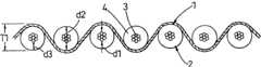
EP0735949A1中描述了一种常规压力垫。该压力垫包括诸如铜丝之类的耐热线股的织物,其中相当大比例的经线或纬线包括硅弹性体。实践中,如图1所示,经线1通常包括成股的或成束的黄铜丝或铜丝,且纬线2通常包括硅覆盖的金属线,具体是其上已挤压硅护套4的成股或成束的铜丝3。由于存在硅4,该压力垫具有很大的回弹性和弹性,而金属线确保压力垫实现从压盘到受压材料的良好的导热性。A conventional pressure pad is described in EP0735949A1. The pressure pad comprises a fabric of heat-resistant strands, such as copper wires, where a substantial proportion of the warp or weft comprises silicon elastomer. In practice, as shown in Figure 1, the warp threads 1 usually consist of strands or bundles of brass or copper wires, and the weft threads 2 usually consist of silicon-coated metal wires, in particular on which a silicon sheath 4 has been extruded. Stranded or bundled copper wire3. Due to the presence of silicon 4, the pressure pad has great resilience and elasticity, while the metal wires ensure that the pressure pad achieves good thermal conductivity from the pressure plate to the material under pressure.
迄今为止,由硅护套覆盖的铜丝是包括成股或成束的七根0.2mm直径的单根铜丝。成股的金属线包括这样的金属线:多股受到正向和受控扭曲而七股中的一股形成其它六股所包围缠绕的芯。图2中示出这种金属线5,其中示出形成中心芯6的线股由围绕其扭曲的六根线股7所围绕。如果线股6、7各具有0.2mm的直径,则可见金属线总直径d1(见图1)是0.6mm。相反,成束金属线包括这样的金属线,其中多根线股以更自由的方式扭曲而它们中的任何一根都不具有中心位置。如果使用0.2mm的七根单股,则这种成束金属线也具有约0.6mm的总直径。经线1和纬线2中的成股或成束金属线中使用的扭曲的程度通常是“15mm捻距(lay)”的量级。捻距表示对扭曲线股中360°扭曲需要的成品金属线的长度。Copper wire covered by a silicon sheath has so far consisted of seven individual copper wires of 0.2 mm diameter in strands or bundles. Stranded wires include wires in which multiple strands are subjected to a positive and controlled twist and one of the seven strands forms a wound core surrounded by the other six strands. Such a
当涂有硅时,硅覆盖纬线2的外径d2通常是1.4mm,因此使硅的壁厚d3为0.4mm。通常,使用这种硅覆盖的纺织压力垫具有2.5mm的初始厚度T1(见图1)且在相对短时间的使用之后它们下沉到约2.0mm的厚度。这是因为经线压入纬线的硅内。在该状态下,压力垫通常在用尽之前可实现200,000次压力循环。由于使用时织物结构最终变平到压力垫在每次压力操作之后不能放松而压力垫失去其回弹性和弹性的程度,所以压力垫就用坏了。When coated with silicon, the outer diameter d2 of the silicon-covered weft 2 is typically 1.4 mm, thus giving a silicon wall thickness d3 of 0.4 mm. Typically, textile pressure pads using such silicon coverings have an initial thickness T1 (see FIG. 1 ) of 2.5 mm and they sink to a thickness of about 2.0 mm after a relatively short period of use. This is because the warp threads are pressed into the silicon of the weft threads. In this state, the pressure pad typically achieves 200,000 pressure cycles before being exhausted. The pressure pad wears out as the fabric structure eventually flattens with use to the point that the pressure pad cannot relax after each pressing operation and the pressure pad loses its resiliency and elasticity.
在压机中使用压力垫施加约35kg/cm2的平均比压,从而压力垫材料的一平方米上的总卸载是350,000kg。典型的压力垫具有每米长度约550根的纬线插入和每米宽度约900的经线纤丝。这意味着每平方米压力垫通常有550×900=495,000的交叉点,在使用时在压机的每次压缩循环过程中各经受约0.707kg的向下负载。使用时,在各交叉点,经线1相当快速地切割穿过纬线2的硅涂层4,且在交叉点由于所施加的压力变形之前,有彼此接触各0.6mm的两根经线1、3。在图3中示意性地示出而未示出任何硅。随着时间过去,在压力垫的连续使用过程中,两根交叉线1、3压入彼此,且其总厚度0.6mm+0.6mm=1.2mm可能减小到约0.8mm。这是压力垫一旦用坏后的典型最终厚度而其已停止起到柔性补偿垫的作用。这时,硅已压入由交叉线1、3形成的金属线网之间的空隙内,且交叉点支承总的向下负载。An average specific pressure of about 35 kg/cm2 was applied using pressure pads in the press so that the total unloading over one square meter of pressure pad material was 350,000 kg. A typical pressure pad has about 550 weft insertions per meter of length and about 900 warp filaments per meter of width. This means that there are typically 550 x 900 = 495,000 intersections per square meter of pressure pad, each experiencing a downward load of about 0.707 kg during each compression cycle of the press in use. In use, at each intersection the warp thread 1 cuts through the silicon coating 4 of the weft thread 2 rather quickly and there are two warp threads 1 , 3 touching each other 0.6mm each before the intersection deforms due to the applied pressure. This is shown schematically in FIG. 3 without any silicon. Over time, during continuous use of the pressure pad, the two intersecting wires 1, 3 are pressed into each other and their total thickness of 0.6mm+0.6mm=1.2mm may decrease to about 0.8mm. This is a typical final thickness of the pressure pad once it has worn out and it has ceased to function as a flexible compensating pad. At this point, the silicon has been pressed into the spaces between the wire mesh formed by the crossing wires 1, 3, and the crossing points support the total downward load.
在类似于上述的常规压力垫用坏之前的压力循环的次数很大程度上取决于被压的层压板的性质。装饰层压片具有固有的弹性和回弹性,从而在压力操作中它们也有助于提供所要求的补偿。但是,由介质和高密度纤维板制成的层压地板具有很小的自然弹性且已发现上述常规压力垫在用于按压这些类型层压片时会相对快速地用坏。The number of pressure cycles before a conventional pressure pad similar to that described above wears out depends largely on the nature of the laminate being pressed. Decorative laminates are inherently elastic and resilient so that they also help provide the required compensation during pressure operations. However, laminate flooring made of media and high density fiberboard has little natural elasticity and it has been found that the conventional pressure pads described above wear out relatively quickly when used to press these types of laminates.
本发明的目的是提供一种与常规压力垫相比能够对更多次数压力循环保持其弹性和补偿能力而其热传递能力不受损失的压力垫。The object of the present invention is to provide a pressure pad capable of maintaining its elasticity and compensating capacity for a greater number of pressure cycles than conventional pressure pads without loss of its heat transfer capacity.
根据本发明,提供一种用在层压机中的压力垫,该压力垫包括耐热线股的织物,其中至少经线和/或纬线包括在弹性体材料的护套内的、由多线股组成的芯,且至少经线或纬线的另一个包括金属线股,且特征在于,组成芯的各线股基本上相互平行并平行于芯的纵向轴线。According to the invention there is provided a pressure pad for use in a laminating machine, comprising a fabric of heat-resistant strands, wherein at least the warp and/or weft threads are comprised of multiple strands contained within a sheath of elastomeric material and at least the other one of the warp threads or the weft threads comprises metal strands, and is characterized in that the strands making up the core are substantially parallel to each other and to the longitudinal axis of the core.
应当理解,组成芯的各线股基本上相互平行并平行于芯的纵向轴线的要求应当理解为在压力垫的尺寸比例内。因此,芯可包括已被松散地的成股或成束的一束线股。It will be appreciated that the requirement that the strands making up the core be substantially parallel to each other and to the longitudinal axis of the core is to be understood within the dimensional proportions of the pressure pad. Thus, the core may comprise a bundle of strands that has been loosely stranded or bundled.
在此所附的独立权利要求书中描述本发明的优选附加特征。Preferred additional features of the invention are described in the independent claims appended hereto.
附图说明Description of drawings
现将参照附图以示例的方式描述本发明,附图中:The invention will now be described by way of example with reference to the accompanying drawings, in which:
图1是在任何使用之前的常规压力垫的放大比例剖视图;Figure 1 is an enlarged scale cross-sectional view of a conventional pressure pad prior to any use;
图2是形成图1所示压力垫的一部分的纬线线股的一段金属芯的立体图;Figure 2 is a perspective view of a section of the metal core of the weft strands forming part of the pressure pad shown in Figure 1;
图3是形成图1所示压力垫的纬线线股和径向线股的金属芯之间的交叉点的示意性立体图,省略了压力垫的硅;Figure 3 is a schematic perspective view of the intersection between the metal cores of the weft strands and radial strands forming the pressure pad shown in Figure 1 , omitting the silicon of the pressure pad;
图4是层压机的示意性竖直剖视图,示出使用常规压力垫时压机内薄板的弯曲;Figure 4 is a schematic vertical cross-sectional view of a laminator showing the bending of the veneers within the press using conventional pressure pads;
图5是根据本发明的压力垫的一部分的纬线线股的一段金属芯的立体图;Figure 5 is a perspective view of a section of the metal core of a weft strand of a portion of a pressure pad according to the present invention;
图6是包括图5所示金属芯的且在使用前的形成根据本发明的压力垫的一部分的纬线线股的第一实施例的剖视图;Figure 6 is a cross-sectional view of a first embodiment of a weft strand forming part of a pressure pad according to the invention, comprising the metal core shown in Figure 5 and prior to use;
图7是类似于图6的视图,但示出使用时和在压力下的纬线线股;Figure 7 is a view similar to Figure 6 but showing the weft strands in use and under pressure;
图8是类似于图3但根据本发明的压力垫的视图;以及Figure 8 is a view similar to Figure 3 but in accordance with the present invention of a pressure pad; and
图9是类似于图6但纬线线股的另一实施例的视图。Figure 9 is a view similar to Figure 6 but of another embodiment of a weft strand.
具体实施方式Detailed ways
根据本发明的压力垫与现有技术类似之处在于其包括耐热线股的织物,其中至少径线或纬线包括在弹性体材料的护套内由多线股组成的芯。现有技术和本发明之间的不同之处在于由弹性体护套覆盖的线股结构。在以下说明书中,将由弹性体护套覆盖的线股描述为纬线线股和作为经线线股的其它线股,但应当理解用在经线中的由弹性体材料覆盖的线股的情况是相反的。这种线股还能用于经线和纬线两者。除了这些线股,在压力垫内还可包含其它类型的线股,例如非金属线股,诸如芳香族聚酰胺纱线、聚酯纱线和玻璃线股以及金属丝围绕的聚酰胺纱线。此外,可以常规方式使用以芳香聚酰胺纱线围绕的铜线股或不锈钢线股之类的混合纤丝。The pressure pad according to the invention is similar to the prior art in that it comprises a fabric of heat-resistant strands, wherein at least the warp or weft comprises a core consisting of multiple strands within a sheath of elastomeric material. The difference between the prior art and the present invention is the structure of the strands covered by the elastomer sheath. In the following specification, the strands covered by the elastomeric sheath are described as the weft strands and the other strands as the warp strands, but it is understood that the opposite is true for the strands covered by the elastomeric material used in the warp . Such strands can also be used for both warp and weft threads. In addition to these strands, other types of strands may also be included within the pressure pad, for example non-metallic strands such as aramid yarns, polyester yarns and glass strands and polyamide yarns surrounded by metal wires. In addition, mixed filaments such as copper strands or stainless steel strands surrounded by aramid yarns can be used in a conventional manner.
还应当理解,弹性体护套不一定如EP0375949A1所述那样由硅制成,而是可包括诸如橡胶之类的任何弹性体材料。但是,较佳的是,护套包括诸如硅或氟硅氧烷之类的硅氧烷。该护套可用任何适当的工艺施加到芯。在大多数情况下,该护套可以常规方式通过将弹性体材料挤压在芯上而制成。It should also be understood that the elastomeric sheath need not be made of silicon as described in EP0375949A1 but may comprise any elastomeric material such as rubber. Preferably, however, the sheath comprises silicone such as silicon or fluorosilicone. The sheath can be applied to the core by any suitable process. In most cases, the sheath can be produced in a conventional manner by extruding an elastomeric material over a core.
芯的线股较佳地是金属线股,但可包括以下中的任何一种,即铜丝、黄铜丝、不锈钢丝、铜合金丝、芳族聚酰胺纱线、玻璃线股或细丝以及芳香族聚酰胺纱线。所使用的线股的选择将取决于压力垫的目的、所要求的热传递的程度和所要求的回弹性或弹性。还必须考虑压力垫的所想要的目的来选择经线。纬线围绕纱线从压力垫的顶部到底部进行纺织。因此形成通过压力垫进行热传递的主要管道。由于该原因,经线通常包括金属线股并可采用金属线的形式,尤其是由铜、黄铜和其它铜合金制成的具有高导热性的金属线。The strands of the core are preferably metal strands but may comprise any of the following, namely copper wire, brass wire, stainless steel wire, copper alloy wire, aramid yarn, glass strand or filament and aramid yarns. The choice of strands used will depend on the purpose of the pressure pad, the degree of heat transfer required and the resiliency or elasticity required. The warp thread must also be chosen taking into account the intended purpose of the pressure pad. The weft is woven around the yarn from the top to the bottom of the pressure pad. The main conduit for heat transfer through the pressure pad is thus formed. For this reason, warp threads generally comprise metal strands and may take the form of metal wires, especially wires made of copper, brass and other copper alloys with high thermal conductivity.
根据本发明的压力垫的实施例的剖视图可能看起来类似于图1所示的剖视图,其中经线1包括金属线,且纬线2包括纤丝,纤丝具有由弹性体材料的护套4所围绕的各单根线股的芯3。但是,如上所述,纬线的结构不同于现有技术的纬线结构,现将参照图5-9更详细地描述其各实施例。A cross-sectional view of an embodiment of a pressure pad according to the invention may look similar to the cross-sectional view shown in FIG. 1 , where the warp threads 1 comprise metal threads and the weft threads 2 comprise filaments with a sheath 4 surrounded by an elastomeric material. The core 3 of each single strand. However, as mentioned above, the structure of the weft threads is different from that of the prior art, embodiments of which will now be described in more detail with reference to Figures 5-9.
参照图5和6,在第一实施例中,纬线纤丝10包括由多个基本上平行的金属线股12制成的金属线的芯11,金属线股已在弹性体材料的护套13内明显地绞扭在一起。芯11的结构如图5所示。如这里可看出的那样,组成芯的线股12形成它们基本上相互平行并平行于芯11的纵向轴线的一束。较佳地是,线股12尚未成股或成束,但应当理解,如果捻距与压力垫的宽度相比足够长,能够使用线股12已被松散地成股或成束的芯11,但其中在压力垫的尺寸比例内它们看起来基本上相互平行。Referring to Figures 5 and 6, in a first embodiment, the
当使用压力垫在层压机中通过沿箭头P方向施加的压力受压时,确保各线股12基本上平行排列的位置变得清楚,如图7所示,芯12内的各线股12可相对于彼此移动并因此倾向于如图8所示变平。相反,在现有技术中,由于各线股12的扭曲特性和其捻距较短,芯6在受压时不能变平。在初始扭变之后其厚度保持不变,即使当在层压机的相当大的压力之下也是如此。When pressed in a laminator using a pressure pad by a pressure applied in the direction of arrow P, the position ensuring that the
如果在芯11内使用七根平行的线股12来代替如现有技术中所使用那样的七根扭曲的线股,则施加标称压力会使芯11变平成总厚度为0.2mm。同样,如果经线纤丝14也包括多根基本上平行的金属线股15,即七根平行线股,则它们也在使用时在压力下变平成总厚度为0.2mm。如图8所示意地示出的那样没有弹性体材料,经线14和纬线10之间的各交叉点将各0.2mm粗的金属线带到一起,从而与现有技术中约1.2mm交叉点厚度相比交叉点处金属线总厚度仅为约0.4mm。此外,压力垫中所使用的金属线股之间交叉点的总数量显著增加。在每米长度有550根纬线插入且每米宽度900根径向端的压力垫中,现有每平方米(550x7)x(900x7)=24,255,000个交叉点。在典型压机中,这在使用过程中在各交叉点处减小98%的向下负载,减小到0.01443kg,即350,000/24,255,000。考虑的其它方式是先前的每个交叉点具有1×1根金属线,现在具有7×7根金属线=49个交叉点。这是98%的增加。If seven
其中具有各经线纤丝14包括多根基本上平行的金属线股15的上述结构的经线很难与之合作。因此,较佳地是,经线包括金属线股15,金属线股15各具有0.2mm数量级的直径和至少25mm的捻距。这种捻距是对15mm的常规捻距的改进,但捻距越大而因此金属线股15中扭曲的最小量越大,就越好。Warp threads having the above-described structure in which each warp filament 14 comprises a plurality of substantially
实践中,在纺织压力垫中,经线穿梭经过纬线上方和下方。在经线纤丝14具有七根基本上平行的金属线股15的压力垫中,压力垫上压力的效果会将平行的经线线股14推入弹性体护套13一段距离,该距离等于其单根直径0.2mm,之后经线的表面就称为与纬线的表面平齐。如果使用约0.4mm的常规壁厚,这相当于是护套可用壁厚的一半,因此在经线细丝和纬线纤丝之间留下约0.2mm作为缓冲。该缓冲使单根0.2mm直径的经线线股14能够舒适地嵌入护套且这给予它们以保护。在现有技术中,0.6mm总直径的扭曲经线会压入护套约0.6mm的距离,但是当护套的壁厚仅为约0.4mm时,这意味着当使用压力垫时,护套易于切穿且经线和纬线的金属丝纤丝几乎直接彼此接触。In practice, in a textile pressure pad, the warp threads pass over and under the weft threads. In a pressure pad where the warp filaments 14 have seven substantially
与现有技术相比压缩期间金属芯11的粗度的减小具有两个有益效果。首先,在压缩期间压力垫本身的厚度显著小于现有技术压力垫的厚度,且因此层压机的加热压盘的表面边缘上更靠近其薄板。因此,这可增加到受压层压片的热传递。其次,弹性体材料的上述缓冲改进压缩后压力垫的恢复,从而可提高压力垫的补偿能力。但是,当压力垫具有从垫的顶部表面穿到底部表面的相同数量的经线纤丝时,压力垫的内在热传递能力不受影响。现将更详细地考虑这些有益效果。The reduction in the thickness of the
如图4所示,在常规层压机中,压在压机的两压盘21之间的板20位于两金属薄板22和两压力垫23之间。压力垫23各位于薄板22之一和压盘21之一之间。薄板22和压力垫23的宽度和长度通常大于被压的板。这形成未受支承的薄板22的边缘区域m,薄板22接收通过压力垫23传递的来自压盘21的压力。由于在板20的边缘周围没有对薄板22进行支承,薄板22倾向于使用板20的边缘作为支点进行弯曲,如箭头f所示。由于沿用作支点的其边缘的不规则高压,该效果引起称为板上“白点”的缺陷,且由于薄板22弯曲远离板20,通常在板20的边缘的2cm内产生的较低压力。在纵长边缘和宽度边缘汇合的板20的角部处该问题恶化。这引起板20的角部上的高压和通常板20的角部5cm至10cm内小区域上的相应压降。“白点”发生在板20已接受不足以令人满意地完成按压工艺的压力处位置。As shown in FIG. 4 , in a conventional laminating machine, a
应当理解,施加到各未受支承的薄板22的弯矩与板20上方和下方受压压力垫与垫在边缘区域m的轻度受压压力垫23之间的厚度差相当。一般而言,该厚度差作为线性量度会与所使用的压力垫23的厚度直接成比例地变化。因此,厚度减小的压力垫会具有其受压区域和边缘区域m之间减小的“厚度差”,且因此在未受支承的薄板区域上产生减小的弯曲效果。接着,与所提供的、没有厚度减小垫的的常规垫相比生产诸如根据本发明的厚度减小的压力垫在压力垫的补偿能力上是有利的。然而,本发明的压力垫还改进了压缩后压力垫的恢复,从而可提高压力垫的补偿能力。现将更详细地考虑该优点。It will be appreciated that the bending moment applied to each
如上所述,通常的情况是根据其所要求的用途,必须达到任何给定压力垫的热传递和回弹性或弹性之间的折衷。然而,在本发明的压力垫压缩之后增加了的恢复意味着可认为是将弹性体护套的外径从常规的1.4mm减小到1.15mm的新的折衷情况。如果同时用三根平行线股(见下文)代替芯11的七根平行线股12,则每根纬线插入的护套材料的体积减小总计约27%。这可相当大地节省护套材料的成本,尤其是如果使用诸如氟硅氧烷之类的昂贵材料更是如此。但是,纬线纤丝10的粗度的减小意味着每米纬线插入的数量可以从约600根增加到约710根,增加18%。这具有两个有益效果。首先,由于经线围绕纬线缠绕并形成“穿过垫”的热导体,而后“穿过垫”导体的总数量以相同的比例增加。因此,这将改进压力垫的热传递能力并能够使压机的循环时间缩短。第二,纬线插入件的数量增加18%抵消了由于弹性体护套直径减小引起的压力垫的弹性的降低。压力垫中弹性体材料的净总量仍然降低14%,但由于纬线的新型结构,压力垫具有相同的弹性并具有与以前相同的补偿能力,但却具有改进的热传递。As noted above, it is often the case that a compromise must be reached between heat transfer and resiliency or elasticity for any given pressure pad, depending on its intended use. However, the increased recovery after compression of the pressure pad of the present invention represents what can be considered a new compromise in reducing the outer diameter of the elastomer sheath from the conventional 1.4 mm to 1.15 mm. If at the same time the seven
在纬线的另一实施例中,不是使用七根平行线股12来形成芯11,而是可使用三根平行线股12。可以预料在大多数情况下,七根平行线股12会包括铜丝。但是,通过使用三根不锈钢线股12来形成芯11可实现与这种多线股芯11类似的强度。这样使用不锈钢具有克服由于压力垫的弹性而遇到的金属疲劳的任何问题的优点。In another embodiment of the weft thread, instead of using seven
如上所述根据本发明的纬线的各实施例都具有如图6所示包括一束基本上平行线股的芯11,芯11在压力下塌陷使得各线股12相对于彼此移动并如图7所示变平。如图9所示,在纬线的另一实施例中,各线股12设置成在不受任何施加的压力时在芯11的基本上相同平面上的基本上相互平行并平行于纵向轴线。这将包括非圆形剖面轮廓的弹性体护套13的挤压。这种挤压需要使用相应地成形的模具,较佳的是,如图9所示的椭圆形模具,尽管也能够使用其它形状,例如方形或矩形。各线股12还能设置成矩阵中的行而不是设置在单个平面上。As described above, each embodiment of the weft thread according to the present invention has a core 11 comprising a bundle of substantially parallel strands as shown in FIG. Flattened as shown. As shown in Figure 9, in another embodiment of the weft, the
从上述可以理解,本发明提供一种比常规压力垫对更多次压力循环保持其弹性和补偿能力而热传递能力不受损失的压力垫。此外,可用增加数量的弹性体材料来生产压力垫,因此又增加补偿能力而压力垫的热传递能力没有任何降低。通常,在使用过程中由于弹性体材料不能恢复而失去补偿性能时就更换压力垫。用本发明的压力垫实现的较大程度的补偿本身是有利的,但其也由于以下原因而延长压力垫的寿命。As can be appreciated from the foregoing, the present invention provides a pressure pad that maintains its elasticity and compensating capabilities for more pressure cycles than conventional pressure pads without loss of heat transfer capability. Furthermore, the pressure pad can be produced with an increased amount of elastomeric material, thus again increasing the compensation capability without any reduction in the heat transfer capability of the pressure pad. Typically, pressure pads are replaced during use when the compensating properties are lost due to the failure of the elastomeric material to recover. The greater degree of compensation achieved with the pressure pad of the present invention is an advantage in itself, but it also prolongs the life of the pressure pad for the following reasons.
1.由于经线中的金属线股不会切入弹性体材料,所以弹性体材料长时间保持完好无损。1. Since the metal strands in the warp do not cut into the elastomeric material, the elastomeric material remains intact for a long time.
2.压力垫中使用的金属线的量可与现有技术中的相同,但生产的金属线的总粗度在使用时显著降低。这意味着弹性体材料形成更大百分比的总压力垫厚度,且因此产生增强了的“弹性”效果。2. The amount of metal wire used in the pressure pad can be the same as in the prior art, but the overall thickness of the metal wire produced is significantly reduced when used. This means that the elastomeric material forms a greater percentage of the total pressure pad thickness, and thus produces an enhanced "springy" effect.
3.压力垫的下方的金属网架可抑制压机中每次循环中压力释放时弹性体材料的恢复。本发明有效地使用0.2mm直径的金属线而不是使用0.6mm直径的金属线形成网架,这种网具有较好的固有柔性而在弹性体材料的恢复方面产生较少的抑制作用。3. The metal mesh frame under the pressure pad can inhibit the recovery of the elastomeric material when the pressure is released in each cycle in the press. The present invention effectively uses 0.2 mm diameter wires rather than 0.6 mm diameter wires to form the grid, which has better inherent flexibility and produces less inhibition in the recovery of the elastomeric material.
Claims (15)
Translated fromChineseApplications Claiming Priority (3)
| Application Number | Priority Date | Filing Date | Title |
|---|---|---|---|
| GB0608677.1 | 2006-05-03 | ||
| GB0608677AGB0608677D0 (en) | 2006-05-03 | 2006-05-03 | Improvements to press pads |
| PCT/GB2007/001597WO2007129041A1 (en) | 2006-05-03 | 2007-05-01 | Improvements to press pads |
Publications (2)
| Publication Number | Publication Date |
|---|---|
| CN101432130A CN101432130A (en) | 2009-05-13 |
| CN101432130Btrue CN101432130B (en) | 2013-10-16 |
Family
ID=36603793
Family Applications (1)
| Application Number | Title | Priority Date | Filing Date |
|---|---|---|---|
| CN2007800157631AActiveCN101432130B (en) | 2006-05-03 | 2007-05-01 | Improvements to pressure pads |
Country Status (11)
| Country | Link |
|---|---|
| US (1) | US7892990B2 (en) |
| EP (1) | EP2013009B1 (en) |
| JP (1) | JP5203354B2 (en) |
| CN (1) | CN101432130B (en) |
| AU (1) | AU2007246870B2 (en) |
| CA (1) | CA2646557C (en) |
| DE (1) | DE202007019506U1 (en) |
| GB (2) | GB0608677D0 (en) |
| PL (1) | PL2013009T3 (en) |
| RU (1) | RU2429970C2 (en) |
| WO (1) | WO2007129041A1 (en) |
Families Citing this family (12)
| Publication number | Priority date | Publication date | Assignee | Title |
|---|---|---|---|---|
| BE1018703A3 (en)* | 2009-03-26 | 2011-07-05 | Flooring Ind Ltd Sarl | METHOD FOR MANUFACTURING PANELS, FLOOR PANEL GIVEN HEREIN AND USE PERSBLEK HEREIN. |
| GB2493738B (en) | 2011-08-17 | 2014-06-11 | Marathon Belting Ltd | Improvements to press pads |
| DE102013100433A1 (en)* | 2013-01-16 | 2014-07-31 | Hueck Rheinische Gmbh | Press pad for a single or multi-floor heating press |
| DE202015006923U1 (en)* | 2015-10-02 | 2015-10-16 | Rolf Espe | Press pad for use in hydraulic single or multi-floor heating presses |
| DE202016000367U1 (en)* | 2016-01-20 | 2016-02-05 | Rolf Espe | Press pad for single and multi-day presses whose silicone elastomer padding layer is applied in a 3D printing process. |
| DE202017003635U1 (en) | 2017-07-11 | 2017-08-22 | Rolf Espe | Press pads with higher thermal conductivity and improved recovery properties for the coating of wood-based panels in hydraulic single and multi-floor heating presses |
| DE202017003632U1 (en)* | 2017-07-11 | 2017-10-20 | Rolf Espe | Pressure compensation fabric, in particular press pads for the equipment of hydraulic single and Mehretagenheizpressen, consisting of a fabric with elastic weft and / or warp threads |
| WO2019168037A1 (en)* | 2018-03-01 | 2019-09-06 | 日立化成株式会社 | Anisotropic thermal conductive resin fiber, anisotropic thermal conductive resin member, and manufacturing method of these |
| WO2019168038A1 (en) | 2018-03-01 | 2019-09-06 | 日立化成株式会社 | Anisotropic thermal conductive resin member and manufacturing method thereof |
| DE102019107005A1 (en)* | 2019-03-19 | 2020-09-24 | Hueck Rheinische Gmbh | Press pad for use in single- or multi-daylight heating presses |
| CN115003997A (en)* | 2020-01-27 | 2022-09-02 | 松下知识产权经营株式会社 | Load sensor |
| DE202022002690U1 (en) | 2022-12-30 | 2024-01-04 | Hueck Rheinische Gmbh | Press pad can be used universally and fixed in hydraulic multi-daylight presses with heating and cooling |
Citations (7)
| Publication number | Priority date | Publication date | Assignee | Title |
|---|---|---|---|---|
| US2372114A (en)* | 1943-03-13 | 1945-03-20 | Westinghouse Electric & Mfg Co | Pad |
| DE2405975A1 (en)* | 1974-02-08 | 1975-08-21 | Goldschmidt Ag Th | Pressure cushions for hot presses - made of resin coated metal fibre mat |
| EP0290653A1 (en)* | 1987-05-14 | 1988-11-17 | Thomas Josef Heimbach GmbH & Co. | Material web |
| EP0292700A1 (en)* | 1987-05-14 | 1988-11-30 | Thomas Josef Heimbach GmbH & Co. | Spiral fabric |
| EP0920983A1 (en)* | 1997-12-05 | 1999-06-09 | Thomas Josef Heimbach Gesellschaft mit beschränkter Haftung & Co. | Press pad |
| EP1300235A1 (en)* | 2001-09-27 | 2003-04-09 | Thomas Josef Heimbach Gesellschaft mit beschränkter Haftung & Co. | Press pad |
| CN1408537A (en)* | 2001-09-27 | 2003-04-09 | 托马斯约瑟夫亨巴赫有限公司 | Pressure pad |
Family Cites Families (7)
| Publication number | Priority date | Publication date | Assignee | Title |
|---|---|---|---|---|
| JPS4843657Y1 (en)* | 1969-12-13 | 1973-12-17 | ||
| JPS5852122Y2 (en)* | 1975-12-09 | 1983-11-28 | イビガワデンキコウギヨウ カブシキガイシヤ | cushion seat |
| GB9421573D0 (en)* | 1994-10-26 | 1994-12-14 | Marathon Belting Ltd | A press pad |
| US6644954B2 (en)* | 1997-05-03 | 2003-11-11 | Advanced Composites Group Ltd. | Pressure transmitters for use in the production of composite components |
| US6737370B2 (en) | 2000-03-21 | 2004-05-18 | Rheinische Filztuchfabrik Gmbh | Press pad containing fluoroelastomer or fluorosilicone elastomer priority claim |
| JP2002103100A (en)* | 2000-09-25 | 2002-04-09 | Casio Comput Co Ltd | Cushioning material |
| RU2235642C2 (en)* | 2002-07-23 | 2004-09-10 | Кручинина Галина Николаевна | Compensating pad for forming press |
- 2006
- 2006-05-03GBGB0608677Apatent/GB0608677D0/ennot_activeCeased
- 2007
- 2007-05-01JPJP2009508456Apatent/JP5203354B2/enactiveActive
- 2007-05-01CACA2646557Apatent/CA2646557C/enactiveActive
- 2007-05-01RURU2008136912Apatent/RU2429970C2/enactive
- 2007-05-01DEDE200720019506patent/DE202007019506U1/ennot_activeExpired - Lifetime
- 2007-05-01EPEP07732630.4Apatent/EP2013009B1/enactiveActive
- 2007-05-01WOPCT/GB2007/001597patent/WO2007129041A1/enactiveApplication Filing
- 2007-05-01AUAU2007246870Apatent/AU2007246870B2/enactiveActive
- 2007-05-01USUS11/722,714patent/US7892990B2/enactiveActive
- 2007-05-01CNCN2007800157631Apatent/CN101432130B/enactiveActive
- 2007-05-01GBGB0814264Apatent/GB2447837B/enactiveActive
- 2007-05-01PLPL07732630Tpatent/PL2013009T3/enunknown
Patent Citations (7)
| Publication number | Priority date | Publication date | Assignee | Title |
|---|---|---|---|---|
| US2372114A (en)* | 1943-03-13 | 1945-03-20 | Westinghouse Electric & Mfg Co | Pad |
| DE2405975A1 (en)* | 1974-02-08 | 1975-08-21 | Goldschmidt Ag Th | Pressure cushions for hot presses - made of resin coated metal fibre mat |
| EP0290653A1 (en)* | 1987-05-14 | 1988-11-17 | Thomas Josef Heimbach GmbH & Co. | Material web |
| EP0292700A1 (en)* | 1987-05-14 | 1988-11-30 | Thomas Josef Heimbach GmbH & Co. | Spiral fabric |
| EP0920983A1 (en)* | 1997-12-05 | 1999-06-09 | Thomas Josef Heimbach Gesellschaft mit beschränkter Haftung & Co. | Press pad |
| EP1300235A1 (en)* | 2001-09-27 | 2003-04-09 | Thomas Josef Heimbach Gesellschaft mit beschränkter Haftung & Co. | Press pad |
| CN1408537A (en)* | 2001-09-27 | 2003-04-09 | 托马斯约瑟夫亨巴赫有限公司 | Pressure pad |
Also Published As
| Publication number | Publication date |
|---|---|
| US7892990B2 (en) | 2011-02-22 |
| AU2007246870B2 (en) | 2012-07-05 |
| JP2009535221A (en) | 2009-10-01 |
| GB2447837A (en) | 2008-09-24 |
| RU2008136912A (en) | 2010-03-10 |
| PL2013009T3 (en) | 2020-04-30 |
| CN101432130A (en) | 2009-05-13 |
| GB0814264D0 (en) | 2008-09-10 |
| DE202007019506U1 (en) | 2013-02-04 |
| JP5203354B2 (en) | 2013-06-05 |
| WO2007129041A1 (en) | 2007-11-15 |
| CA2646557C (en) | 2014-02-11 |
| RU2429970C2 (en) | 2011-09-27 |
| AU2007246870A1 (en) | 2007-11-15 |
| GB2447837B (en) | 2011-07-13 |
| CA2646557A1 (en) | 2007-11-15 |
| EP2013009B1 (en) | 2019-10-09 |
| US20080311811A1 (en) | 2008-12-18 |
| EP2013009A1 (en) | 2009-01-14 |
| GB0608677D0 (en) | 2006-06-14 |
Similar Documents
| Publication | Publication Date | Title |
|---|---|---|
| CN101432130B (en) | Improvements to pressure pads | |
| US5855733A (en) | Press pad | |
| CN100439089C (en) | Pressure pad | |
| HU219898B (en) | Pressing device | |
| US20040023582A1 (en) | Press pad for multi-daylight presses | |
| SK284457B6 (en) | Press pad | |
| AU734059B2 (en) | Pressing cushion | |
| WO2000001522A1 (en) | Improvements to press pads | |
| CN103781622B (en) | Improvements to press pads | |
| EP2347894B1 (en) | Pressure pad | |
| CN2320405Y (en) | High-temperature buffer | |
| JP7302003B2 (en) | Press pads for use with single-stage hot presses or multi-stage hot presses | |
| WO2004054788A1 (en) | Knitted press pad |
Legal Events
| Date | Code | Title | Description |
|---|---|---|---|
| C06 | Publication | ||
| PB01 | Publication | ||
| C10 | Entry into substantive examination | ||
| SE01 | Entry into force of request for substantive examination | ||
| C14 | Grant of patent or utility model | ||
| GR01 | Patent grant |