CN101431611A - Image processing method, image processing apparatus, image processing program, and image file format - Google Patents
Image processing method, image processing apparatus, image processing program, and image file formatDownload PDFInfo
- Publication number
- CN101431611A CN101431611ACNA2008101781224ACN200810178122ACN101431611ACN 101431611 ACN101431611 ACN 101431611ACN A2008101781224 ACNA2008101781224 ACN A2008101781224ACN 200810178122 ACN200810178122 ACN 200810178122ACN 101431611 ACN101431611 ACN 101431611A
- Authority
- CN
- China
- Prior art keywords
- image
- resolution
- mentioned
- image processing
- learning
- Prior art date
- Legal status (The legal status is an assumption and is not a legal conclusion. Google has not performed a legal analysis and makes no representation as to the accuracy of the status listed.)
- Pending
Links
Images


Classifications
- G—PHYSICS
- G06—COMPUTING OR CALCULATING; COUNTING
- G06T—IMAGE DATA PROCESSING OR GENERATION, IN GENERAL
- G06T3/00—Geometric image transformations in the plane of the image
- G06T3/40—Scaling of whole images or parts thereof, e.g. expanding or contracting
- H—ELECTRICITY
- H04—ELECTRIC COMMUNICATION TECHNIQUE
- H04N—PICTORIAL COMMUNICATION, e.g. TELEVISION
- H04N23/00—Cameras or camera modules comprising electronic image sensors; Control thereof
- H04N23/95—Computational photography systems, e.g. light-field imaging systems
- H04N23/951—Computational photography systems, e.g. light-field imaging systems by using two or more images to influence resolution, frame rate or aspect ratio
- H—ELECTRICITY
- H04—ELECTRIC COMMUNICATION TECHNIQUE
- H04N—PICTORIAL COMMUNICATION, e.g. TELEVISION
- H04N5/00—Details of television systems
- H04N5/222—Studio circuitry; Studio devices; Studio equipment
- H04N5/262—Studio circuits, e.g. for mixing, switching-over, change of character of image, other special effects ; Cameras specially adapted for the electronic generation of special effects
- H04N5/2628—Alteration of picture size, shape, position or orientation, e.g. zooming, rotation, rolling, perspective, translation
- H—ELECTRICITY
- H04—ELECTRIC COMMUNICATION TECHNIQUE
- H04N—PICTORIAL COMMUNICATION, e.g. TELEVISION
- H04N7/00—Television systems
- H04N7/01—Conversion of standards, e.g. involving analogue television standards or digital television standards processed at pixel level
- H04N7/0135—Conversion of standards, e.g. involving analogue television standards or digital television standards processed at pixel level involving interpolation processes
Landscapes
- Engineering & Computer Science (AREA)
- Theoretical Computer Science (AREA)
- Multimedia (AREA)
- Signal Processing (AREA)
- Computing Systems (AREA)
- Physics & Mathematics (AREA)
- General Physics & Mathematics (AREA)
- Image Processing (AREA)
- Studio Devices (AREA)
- Processing Or Creating Images (AREA)
- Image Analysis (AREA)
Abstract
Translated fromChinese
Description
Translated fromChinese本申请是申请日为2005年11月18日、申请号为200580040954.4、发明名称为“图像处理方法、图像处理装置、图像处理程序以及图像文件格式”的分案申请。This application is a divisional application with a filing date of November 18, 2005, an application number of 200580040954.4, and an invention title of "image processing method, image processing device, image processing program, and image file format".
技术领域technical field
本发明涉及图像处理技术,特别涉及用以进行例如动画高解像度化等解像度转换的技术。The present invention relates to image processing technology, and in particular to a technology for performing resolution conversion such as high-resolution animation.
背景技术Background technique
由于数码映像机器网络的普及,在各种输入、输出机器中使用不同规格形式的数码图像已经成为非常普遍的现象。特别是在图像的尺寸中存在有从低解像度到超高解像度那样的多种种类。在静止图像中,民生用数码静像摄影机的摄像元件的像素多为500万像素以上,现在还有超过1000万像素的产品,正在逐步对数码相片印刷实现充分的高解像度化。Due to the popularization of the digital image machine network, it has become a very common phenomenon to use digital images of different specifications in various input and output machines. In particular, there are various types of image sizes ranging from low resolution to super high resolution. For still images, most consumer digital still cameras have imaging elements of more than 5 million pixels, and there are products with more than 10 million pixels, and digital photo printing is gradually realizing sufficient high-resolution.
不过,能够想像出作为今后的数码图像的用途,为了生成逼真的CG,而切出实际照片图像的一部分,将其放大或者变形来进行纹理变换(mapping)这样的用途将会得到发展。并且,在电子商业交易和医疗等用途中,还存在有将商品和患部出示在显示器上时,可自由地将感兴趣的图像区域进行放大显示这样的交互式(interactive)显示用途。由于在某种程度上实现了静止图像的高解像度化,因此能够预测到今后对动画增大解像度,特别是对如电影那样,将帧图像的每一个作为静止图像通用那样的高解像度动画的需求将会增大。However, it is conceivable that as a future application of digital images, in order to generate a realistic CG, a part of an actual photo image is cut out, enlarged or deformed, and texture transformation (mapping) will be developed. In addition, in applications such as electronic business transactions and medical treatment, there are interactive display applications in which an image area of interest can be freely enlarged and displayed when products and affected parts are displayed on the display. Since the higher resolution of still images has been realized to some extent, it can be predicted that the resolution of animation will be increased in the future, especially for high-resolution animation where each frame image is used as a still image like a movie. will increase.
从而,要求更高的图像数码的高解像度化。但为了响应此要求,不仅要求摄像元件的进一步发展,而且必须使数码图像处理高度化。Therefore, higher resolution of digital image is required. However, in order to respond to this demand, not only the further development of imaging elements is required, but also advanced digital image processing is required.
作为图像高解像度化的应用领域,具有摄影机那样的输入图像的领域和电视机那样的显示图像的领域。本发明主要涉及对输入图像类的应用。The field of application of higher image resolution includes the field of inputting images such as cameras and the field of displaying images such as televisions. The invention mainly relates to the application to the input image class.
本领域的现有技术是一边使用低解像度的摄影元件,一边用光学变焦机构来最终获得高视角、高解像度的静止图像的技术。The prior art in this field is a technique for finally obtaining a still image with a high viewing angle and high resolution by using an optical zoom mechanism while using a low-resolution imaging element.
例如,在专利文献1中,公开有在考虑到变焦率的情况下,将边进行连续的光学变焦,边拍摄的动画一个接一个加在图像缓冲器上来生成一张广视角/高解像度静止图像的摄影机。并且,在专利文献2中,公开有逐步让变焦镜头从远距侧(telephoto side)的最大变焦位置移到广角(wide-angle)侧的最小变焦位置,将各位置中的多个图像写入磁带,在读出时对各图像进行缩小或放大,将其转换为相同倍率的图像之后,再重叠起来,在主存储器上生成高解像度的图像的技术。而且,在专利文献3中,公开有边调整光学变焦图像的位置,边将其相互贴在一起,来生成一张高解像度静止图像,组合为异质结构的金字塔形式的技术。For example, in
并且,在专利文献4中,公开有不用光学变焦,从低解像度和高解像度的图像中生成高解像度的动画的技术。即,从用低解像度、高速帧速率的摄影机进行的连续的动画中的对应点信息中,找出用低解像度、低速摄影机进行的较少帧数的动画内的对应点,利用时间方向的插补(interpolate)技术,来从高解像度图像中生成高解像度的连续帧的动画。Furthermore,
并且,在专利文献5中,公开有从低解像度和高解像度的图像中生成高解像度的动画的技术。在上述专利文献4中,将动作附加在高解像度的静止图像上,来使其动画化,而在该专利文献5的技术中,在每个取样时间中,使低解像度动画的一个帧和高解像度静止图像相对应,在空间上插补动画,实现高解像度化。Furthermore,
【专利文献1】特开平11—252428号公报(图3)[Patent Document 1] Japanese Unexamined Publication No. 11-252428 (Fig. 3)
【专利文献2】特开平8—25177号公报(图2)[Patent Document 2] Japanese Unexamined Publication No. 8-25177 (Fig. 2)
【专利文献3】美国专利第6681056号说明书[Patent Document 3] Specification of US Patent No. 6681056
【专利文献4】特开2003—203237号公报(图1)[Patent Document 4] JP-A-2003-203237 Gazette (Fig. 1)
【专利文献5】专利第3240339号公报(图14)[Patent Document 5] Patent No. 3240339 (Fig. 14)
不过,在现有技术中存在有下述问题。However, there are the following problems in the prior art.
首先,在专利文献1~3中所示的那样的用光学变焦来生成高解像度图像的技术中,存在有所生成的高解像度图像被限定为静止图像的问题。事实上数码动画的解像度与数码静止图像相比较低,非常期望实现数码动画的高解像度化。First, in the techniques for generating high-resolution images using optical zoom as disclosed in
对于动画的高解像度,在现有技术中存在有下述3个问题。第一、当将专利文献1~3使用在动画中时,必须执行录象过程和图像取得过程这两个过程,该录象过程是通过按照摄影者的意图的摄影技巧(camera work)来拍摄动画的过程,该图像取得过程是通过光学变焦取得部分图像的过程。当在不同的时间内进行了这两个过程时,高解像度图像和低解像度图像的各区域的对应关系变得不明确。并且,为了对图像内的各区域求出空间对应关系,必须对各区域进行用光学变焦取得图像的过程,但是这样做会造成反复执行选择画面内的微小区域、让其光学变焦这样的工作,使作业变得复杂,要通过人来实现它是很不现实的。Regarding the high resolution of animation, there are the following three problems in the prior art. First, when using
第二、专利文献4所公开的是通过时间上的插补技术来让高解像度静止图像的帧速率提高的技术,由于用运动向量将动作附加在静止图像上,因此生成的动画不会强于静止图像的连续。特别是虽然在动画中通过平移(panning)、俯仰(tilting)、变焦(zooming)等这样的摄影技巧、和让被摄物自身变形及旋转等能够产生平稳变化的各种场景,但是却难以通过静止图像的插补技术生成所有的高解像度图像。Second, what
第三、专利文献5所公开的是从低解像度的动画来生成空间上高解像度动画的技术。具体地说,由于用时间轴上的分散点来使动画和静止图像相对应,因此通过对没有存在对应信息的动画帧,使用对应关系已被判明的帧信息,探索类似的信号电平的边缘(edge),认为它就是同一被摄物的移动,来决定在空间上插补的像素。这样一来,不仅存在有探索处理的负担太重这样的问题,而且当与被摄物的距离发生变化,或产生了被摄物变形时,不能实现对应关系,造成难以获得高解像度化的可能性很高。Thirdly,
发明内容Contents of the invention
鉴于上述问题,本发明的目的在于:作为进行动画的高解像度化那样的图像解像度转换的技术,能够实现处理量较少且精度较高的解像度转换。In view of the above-mentioned problems, an object of the present invention is to realize high-precision resolution conversion with a small amount of processing as a technology for image resolution conversion such as high-resolution animation.
本发明通过从对被摄物取得的解像度彼此不同的多个图像中,对每个被摄物特性学习解像度转换规则,根据被摄物特性对所取得的原图像进行区域分割,将所学习的与对应于上述区域的被摄物特性有关的解像度转换规则使用在被分割的区域中,来转换原图像的解像度。The present invention learns a resolution conversion rule for each subject characteristic from a plurality of images obtained with different resolutions of the subject, performs region segmentation on the obtained original image according to the subject characteristic, and divides the learned The resolution conversion rules related to the characteristics of the subject corresponding to the above regions are used in the divided regions to convert the resolution of the original image.
根据本发明,首先,对于被摄物,从解像度彼此不同的多个图像中,对每个被摄物特性学习解像度转换规则。并且,根据被摄物特性对成为解像度转换对象的原图像进行区域分割。将所学习的与对应于上述区域的被摄物特性有关的解像度转换规则使用在被分割的区域中,来转换原图像的解像度。即,由于原图像的解像度转换是通过每个被摄物特性的解像度转换规则来执行的,因此能够实现反映出被摄物特性的精度较高的解像度转换。并且,由于不管在原图像上的位置如何,对被摄物特性相同的区域使用相同的解像度转换规则,因此大幅度降低了图像处理的处理量。According to the present invention, first, for a subject, the resolution conversion rule is learned for each subject characteristic from a plurality of images having mutually different resolutions. In addition, the original image to be converted into a resolution is divided into regions according to the characteristics of the subject. The learned resolution conversion rules related to the characteristics of the subject corresponding to the above regions are used in the divided regions to convert the resolution of the original image. That is, since the resolution conversion of the original image is performed according to the resolution conversion rule for each subject characteristic, high-precision resolution conversion reflecting the subject characteristic can be realized. Moreover, since the same resolution conversion rule is used for areas with the same characteristics of the subject regardless of the position on the original image, the processing load of image processing is greatly reduced.
(发明的效果)(effect of invention)
根据本发明,能够用较少的图像处理量实现反映出被摄物特性的精度较高的解像度转换。因此,本发明适用于使低解像度的动画高解像度化的情况。由于能够用可从各像素算出的光学特性来作为被摄物特性,因此还能够很容易地使用于通过复杂的摄影技巧、或与被摄物的距离发生变化、变形、旋转等进行平稳变化的各种场景,能够生成高质量的动画。并且,由于本发明并不限定于高解像度化,还能够使用于一般的解像度转换,因此能够有效地利用于携带电话那样的用以对低解像度显示类的图像进行显示的低解像度图像的生成。According to the present invention, it is possible to realize high-precision resolution conversion reflecting the characteristics of an object with a small amount of image processing. Therefore, the present invention is suitable for increasing the resolution of a low-resolution moving image. Since the optical characteristics that can be calculated from each pixel can be used as the object characteristics, it can also be easily used for complex photography techniques, or changes in the distance from the object, deformation, rotation, etc. Various scenes, capable of generating high-quality animations. Furthermore, since the present invention is not limited to high-resolution, but can also be used for general resolution conversion, it can be effectively used for generation of low-resolution images for displaying low-resolution display images such as mobile phones.
附图说明Description of drawings
图1为表示本发明的第一实施例所涉及的图像处理方法中的学习过程的流程图。FIG. 1 is a flowchart showing a learning procedure in the image processing method according to the first embodiment of the present invention.
图2为表示本发明的第一实施例所涉及的图像处理方法中的录象过程的流程图。FIG. 2 is a flow chart showing a video recording process in the image processing method according to the first embodiment of the present invention.
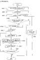
图3为表示本发明的第一实施例所涉及的图像处理方法中的高解像度化过程的流程图。FIG. 3 is a flowchart showing a high-resolution process in the image processing method according to the first embodiment of the present invention.
图4为表示学习过程和录象过程的例子的示意图。Fig. 4 is a diagram showing an example of a learning process and a video recording process.
图5为表示本发明的第二实施例所涉及的图像处理方法中的学习过程的流程图。5 is a flowchart showing a learning procedure in the image processing method according to the second embodiment of the present invention.
图6为表示将图像转换为纹理特征量的转换方法的一个例图。FIG. 6 is an illustration showing an example of a conversion method for converting an image into texture feature quantities.
图7为表示转换后的纹理特征量的图。FIG. 7 is a diagram showing texture feature quantities after conversion.
图8为用以说明学习结束材质的记录的图。FIG. 8 is a diagram for explaining the recording of the learned material.
图9为用以说明目标区域和光学变焦的关系图。FIG. 9 is a diagram illustrating the relationship between the target area and optical zoom.
图10为用以具体说明生成电码本(code book)的图。FIG. 10 is a diagram specifically illustrating generation of a code book.
图11为用以具体说明生成电码本的图。FIG. 11 is a diagram for specifically explaining generation of a codebook.
图12为表示变焦图像和电码本关系的图。Fig. 12 is a diagram showing a relationship between a zoom image and a codebook.
图13为表示本发明的第二实施例所涉及的图像处理方法中的录象过程的流程图。Fig. 13 is a flow chart showing the video recording process in the image processing method according to the second embodiment of the present invention.
图14为表示材质图像的一个例子的示意图。FIG. 14 is a schematic diagram showing an example of a texture image.
图15为表示本发明的第二实施例中的图像文件格式的图。Fig. 15 is a diagram showing an image file format in the second embodiment of the present invention.
图16为表示本发明的第二实施例所涉及的图像处理方法中的高解像度化过程的流程图。FIG. 16 is a flowchart showing a high-resolution process in the image processing method according to the second embodiment of the present invention.
图17为表示本发明的第三实施例所涉及的图像处理装置的方块图。FIG. 17 is a block diagram showing an image processing device according to a third embodiment of the present invention.
图18为学习结束区域显示部的显示例。Fig. 18 is a display example of a learning end area display unit.
图19为学习结束区域显示部的学习之后的显示例。Fig. 19 is a display example after learning of the learning end area display unit.
图20为表示可见光/光谱摄影部的结构例的图。FIG. 20 is a diagram showing a configuration example of a visible light/spectrum imaging unit.
图21为表示光谱图像中的各频带(band)的波长感度的坐标图。Fig. 21 is a graph showing the wavelength sensitivity of each band in a spectral image.
图22为表示本发明的第四实施例所涉及的图像处理装置的方块图。FIG. 22 is a block diagram showing an image processing device according to a fourth embodiment of the present invention.
图23为表示光轴变焦机构的一个例子的示意图。Fig. 23 is a schematic diagram showing an example of an optical axis zoom mechanism.
图24为表示本发明的第四实施例所涉及的摄影机的利用例和目标区域的设定例的图。24 is a diagram showing an example of use of a camera and an example of setting of a target area according to a fourth embodiment of the present invention.
图25为表示本发明的第四实施例中的学习过程的流程图。Fig. 25 is a flowchart showing the learning process in the fourth embodiment of the present invention.
图26为表示本发明的第四实施例中的学习过程和录象过程的时间关系的时间图。Fig. 26 is a time chart showing the temporal relationship between the learning process and the recording process in the fourth embodiment of the present invention.
图27为表示本发明的第五实施例所涉及的图像处理装置的方块图。FIG. 27 is a block diagram showing an image processing device according to a fifth embodiment of the present invention.
图28为表示本发明的第五实施例中的图像录象过程的流程图。Fig. 28 is a flowchart showing the image recording process in the fifth embodiment of the present invention.
图29为表示本发明的第五实施例中的低解像度及高解像度图像、和被摄物特性空间的关系的概念图。Fig. 29 is a conceptual diagram showing the relationship between low-resolution and high-resolution images and the object characteristic space in the fifth embodiment of the present invention.
图30为表示本发明的第六实施例所涉及的图像处理装置的结构的方块图。FIG. 30 is a block diagram showing the configuration of an image processing device according to a sixth embodiment of the present invention.
图31为表示本发明的第六实施例中的低解像度及高解像度图像、和被摄物特性空间关系的概念图。FIG. 31 is a conceptual diagram showing the spatial relationship between low-resolution and high-resolution images and object characteristics in the sixth embodiment of the present invention.
图32为表示本发明的第六实施例中的高解像度图像的摄影时间的例图。FIG. 32 is an example diagram showing the shooting time of a high-resolution image in the sixth embodiment of the present invention.
图33为表示本发明的第六实施例中的低解像度图像和高解像度图像的对应关系图。FIG. 33 is a diagram showing the correspondence relationship between low-resolution images and high-resolution images in the sixth embodiment of the present invention.
图34为表示本发明的第六实施例中的录象过程的流程图。Fig. 34 is a flowchart showing the video recording process in the sixth embodiment of the present invention.
图35为表示本发明的第六实施例中的图像文件格式的图。Fig. 35 is a diagram showing an image file format in the sixth embodiment of the present invention.
图36为表示本发明的第六实施例中的高解像度化的例子的示意图。Fig. 36 is a schematic diagram showing an example of high resolution in the sixth embodiment of the present invention.
图37为表示本发明的第七实施例所涉及的图像处理装置的结构的方块图。FIG. 37 is a block diagram showing the configuration of an image processing device according to a seventh embodiment of the present invention.
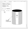
图38为本发明的第七实施例中的表面反射分割图像的显示例。Fig. 38 is a display example of a surface reflection divided image in the seventh embodiment of the present invention.
图39为表示本发明的第七实施例中的镜面反射/扩散反射分离摄影部的结构例图。Fig. 39 is a diagram showing a configuration example of a specular reflection/diffuse reflection separation imaging unit in a seventh embodiment of the present invention.
图40为表示本发明的第七实施例中的学习过程的图。Fig. 40 is a diagram showing a learning process in the seventh embodiment of the present invention.
图41为表示本发明的第七实施例中的动画记录过程的图。Fig. 41 is a diagram showing the motion picture recording process in the seventh embodiment of the present invention.
图42为表示本发明的第七实施例中的高解像度化过程的图。Fig. 42 is a diagram showing the high-resolution process in the seventh embodiment of the present invention.
图43为表示本发明的第八实施例所涉及的图像处理装置的结构的方块图。FIG. 43 is a block diagram showing the configuration of an image processing device according to an eighth embodiment of the present invention.
图44为表示本发明的第八实施例中的学习过程的图。Fig. 44 is a diagram showing a learning process in the eighth embodiment of the present invention.
图45为表示本发明的第八实施例中的动画记录过程的图。Fig. 45 is a diagram showing the motion picture recording process in the eighth embodiment of the present invention.
图46为表示本发明的第八实施例中的高解像度化过程的图。Fig. 46 is a diagram showing the high-resolution process in the eighth embodiment of the present invention.
(符号的说明)(explanation of symbols)
TA1—目标区域;IMa、IMb、IMc—图像;301—变焦镜头;302—变焦控制部;303—可见光/光谱摄影部;304—光谱图像生成部;305—可见光图像生成部;306—材质图像生成部;307—纹理特征转换部;308—学习结束区域分割部;309—学习结束区域显示部(显示部);311—纹理特征学习部;313—学习按钮;401—光轴可变焦机构;402—光轴可变焦控制部;404—摄影机工作显示部;406—照明推定部;407—录象许可部;603—低解像度摄影元件;604—高解像度摄影元件;701—镜面反射/扩散反射分离摄影部;711—镜面/扩散比例图像;728—镜面反射图像;729—扩散反射图像;1501—图像数据;1502—区域分割图像数据;1503—高解像度化参数数据;3501—高解像度化参数数据。TA1—target area; IMa, IMb, IMc—image; 301—zoom lens; 302—zoom control unit; 303—visible light/spectral photography unit; 304—spectral image generation unit; 305—visible light image generation unit; 306—material image Generation section; 307—texture feature conversion section; 308—learning end area segmentation section; 309—learning end area display section (display section); 311—texture feature learning section; 313—learning button; 401—optical axis zoom mechanism; 402—Optical axis variable focus control unit; 404—Camera work display unit; 406—Illumination estimation department; 407—Video permission department; 603—Low resolution photographic element; 604—High resolution photographic element; 701—Specular reflection/diffuse reflection Separation photography section; 711—specular/diffusion ratio image; 728—specular reflection image; 729—diffuse reflection image; 1501—image data; 1502—area segmentation image data; 1503—high resolution parameter data; 3501—high resolution parameter data.
具体实施方式Detailed ways
在本发明的第一方面,提供一种包括第一步骤、第二步骤和第三步骤的图像处理方法,在该第一步骤中,对被摄物取得解像度彼此不同的多个图像,针对每个被摄物特性从该多个图像中学习解像度转换规则;在该第二步骤中,取得原图像,根据被摄物特性对该原图像进行区域分割;在该第三步骤中,通过对在上述第二步骤中所分割的区域,使用在上述第一步骤中所学习的、与对应于上述区域的被摄物特性相关的解像度转换规则,来转换上述原图像的解像度。In a first aspect of the present invention, there is provided an image processing method including a first step, a second step, and a third step. In the first step, a plurality of images having different resolutions are obtained for a subject, and for each A subject characteristic learns the resolution conversion rule from the plurality of images; in the second step, the original image is obtained, and the original image is segmented according to the subject characteristic; in the third step, by For the region divided in the second step, the resolution of the original image is converted using the resolution conversion rule learned in the first step and related to the characteristics of the object corresponding to the region.
在本发明的第二方面,提供一种上述被摄物特性是不受摄影距离约束的光学特性的第一方面的图像处理方法。In a second aspect of the present invention, there is provided an image processing method according to the first aspect in which the above-mentioned subject characteristics are optical characteristics independent of the shooting distance.
在本发明的第三方面,提供一种上述光学特性是从图像的光谱反射率数据或红外线光谱放射率数据中取得的第二方面的图像处理方法。In a third aspect of the present invention, there is provided an image processing method in the second aspect in which the above-mentioned optical characteristics are obtained from spectral reflectance data or infrared spectral emissivity data of an image.
在本发明的第四方面,提供一种上述被摄物特性是被摄物表面的材质的第一方面的图像处理方法。In a fourth aspect of the present invention, there is provided an image processing method according to the first aspect in which the characteristic of the subject is the material of the surface of the subject.
在本发明的第五方面,提供一种上述被摄物特性是被摄物表面的反射状态的第一方面的图像处理方法。In a fifth aspect of the present invention, there is provided an image processing method according to the first aspect in which the characteristic of the subject is the reflective state of the surface of the subject.
在本发明的第六方面,提供一种上述解像度转换规则是描述具有不同解像度的图像之间的纹理特征向量的对应关系的规则的第一方面的图像处理方法。In a sixth aspect of the present invention, there is provided an image processing method according to the first aspect that the above-mentioned resolution conversion rule is a rule describing the corresponding relationship of texture feature vectors between images with different resolutions.
在本发明的第七方面,提供一种包括:决定被摄物的目标区域的步骤;取得与上述目标区域有关的具有不同解像度的第一及第二图像的步骤;生成使上述第一及第二图像相互对应的解像度转换规则的步骤;取得上述目标区域中的被摄物特性的步骤;以及使上述解像度转换规则和被摄物特性相对应,并且将相对应的解像度转换规则和被摄物特性记录在存储设备中的步骤。In the seventh aspect of the present invention, there is provided a method comprising: a step of determining a target area of an object; a step of obtaining first and second images with different resolutions related to the target area; generating the above first and second images The steps of the resolution conversion rules corresponding to the two images; the step of obtaining the characteristics of the subject in the target area; A step in which properties are recorded in a storage device.
在本发明的第八方面,提供一种包括下述步骤的图像处理方法,这些步骤是:取得被摄物的静止图像或活动图像的步骤;以及根据被摄物特性对所取得的图像进行区域分割的步骤。In an eighth aspect of the present invention, there is provided an image processing method comprising the steps of: obtaining a still image or a moving image of a subject; and performing regionalization on the obtained image according to the characteristics of the subject. Split steps.
在本发明的第九方面,提供一种包括下述步骤的图像处理方法,这些步骤是:取得原图像、和表示上述原图像中的根据被摄物特性所分割的区域的区域分割信息的步骤;以及通过对上述区域分割信息所表示的区域,使用对应于上述区域的被摄物特性所涉及的解像度转换规则,来转换上述原图像的解像度的步骤。In a ninth aspect of the present invention, there is provided an image processing method comprising the steps of: obtaining an original image and region segmentation information representing regions in the original image that are segmented according to the characteristics of the subject ; and a step of converting the resolution of the original image by using a resolution conversion rule related to the subject characteristics corresponding to the region indicated by the region division information.
在本发明的第十方面,提供一种包括取得部、规则生成部和区域分割图像生成部的图像处理装置,该取得部构成为能够对被摄物的目标区域取得具有不同解像度的第一及第二图像、和表示被摄物特性的第三图像;该规则生成部从上述第一及第二图像中生成使该第一及第二图像相互对应的解像度转换规则;该区域分割图像生成部从上述第三图像中生成根据被摄物特性而被区域分割了的区域分割图像。In a tenth aspect of the present invention, there is provided an image processing device including an acquisition unit, a rule generation unit, and a segmented image generation unit, wherein the acquisition unit is configured to be able to acquire first and second images with different resolutions for target areas of a subject. The second image, and the third image representing the characteristics of the subject; the rule generation unit generates a resolution conversion rule for making the first and second images correspond to each other from the first and second images; the segmented image generation unit A region-divided image divided into regions according to the characteristics of the subject is generated from the third image.
在本发明的第十一方面,提供一种上述取得部将由被摄物的光谱信息构成的光谱图像作为上述第三图像取得的第十方面的图像处理装置。In an eleventh aspect of the present invention, there is provided the image processing device of the tenth aspect in which the acquisition unit acquires, as the third image, a spectral image composed of spectral information of an object.
在本发明的第十二方面,提供一种上述取得部将表示被摄物表面的镜面反射成分和扩散反射成分的比例的镜面/扩散比例图像作为上述第三图像取得的第十方面的图像处理装置。In a twelfth aspect of the present invention, there is provided the image processing of the tenth aspect in which the acquisition unit acquires, as the third image, a specular surface/diffusion ratio image representing a ratio of a specular reflection component and a diffuse reflection component on a surface of an object. device.
在本发明的第十三方面,提供一种上述取得部分别对镜面反射图像和扩散反射图像取得具有不同解像度的第一及第二图像的第十方面的图像处理装置。In a thirteenth aspect of the present invention, there is provided the image processing device of the tenth aspect in which the acquisition unit acquires first and second images having different resolutions for the specular reflection image and the diffuse reflection image, respectively.
在本发明的第十四方面,提供一种上述取得部具有变焦镜头,利用光学变焦法取得上述第一及第二图像的第十方面的图像处理装置。In a fourteenth aspect of the present invention, there is provided the image processing device of the tenth aspect in which the acquisition unit has a zoom lens and acquires the first and second images by an optical zoom method.
在本发明的第十五方面,提供一种包括用以从装置的外部指示生成解像度转换规则的学习按钮的第十方面的图像处理装置。In a fifteenth aspect of the present invention, there is provided the image processing apparatus of the tenth aspect including a learning button to instruct generation of a resolution conversion rule from outside the apparatus.
在本发明的第十六方面,提供一种包括用以显示上述区域分割图像的显示部的第十方面的图像处理装置。According to a sixteenth aspect of the present invention, there is provided the image processing apparatus according to the tenth aspect, which includes a display unit for displaying the above-mentioned region-divided image.
在本发明的第十七方面,提供一种上述取得部具有光轴可变焦机构,利用该光轴可变焦机构对所指定的目标区域进行光学变焦,取得上述第一及第二图像的第十方面的图像处理装置。In a seventeenth aspect of the present invention, there is provided that the above-mentioned acquisition unit has an optical axis zoom mechanism, and by using the optical axis zoom mechanism to perform optical zoom on a designated target area to obtain the tenth image of the first and second images. Aspect image processing device.
在本发明的第十八方面,提供一种具有静止图像摄影功能和自拍机构,当进行使用了上述自拍机构的静止图像摄影时,在摄影之前的计时器工作期间,上述取得部进行上述第一、第二及第三图像的取得的第十七方面的图像处理装置。In an eighteenth aspect of the present invention, there is provided a still image shooting function and a self-timer mechanism, wherein when taking a still image using the self-timer mechanism, the acquisition unit performs the first . The image processing device according to the seventeenth aspect of acquiring the second and third images.
在本发明的第十九方面,提供一种包括摄影功能、和检测照明环境变化的照明推定部,当在摄影期间,由上述照明推定部检测出照明环境的变化时,将要重新生成解像度转换规则的必要性通知给摄影者的第十方面的图像处理装置。In a nineteenth aspect of the present invention, there is provided an illumination estimation unit including a photographing function and detecting a change in the illumination environment, and when a change in the illumination environment is detected by the illumination estimation unit during photography, the resolution conversion rule is regenerated. The image processing apparatus of the tenth aspect that notifies the photographer of the necessity.
在本发明的第二十方面,提供一种包括:摄影功能;以及在需要生成解像度转换规则时禁止摄影的功能的第十方面的图像处理装置。In a twentieth aspect of the present invention, there is provided the image processing apparatus of the tenth aspect including: a photographing function; and a function of prohibiting photographing when it is necessary to generate a resolution conversion rule.
在本发明的第二十一方面,提供一种包括动画录象功能,上述取得部构成为能够与动画录象并行地执行上述第一及第二图像的取得的第十方面的图像处理装置。In a twenty-first aspect of the present invention, there is provided an image processing device according to the tenth aspect including a video recording function, wherein the acquisition unit is configured to execute acquisition of the first and second images in parallel with the video recording.
在本发明的第二十二方面,提供一种当使上述第一及第二图像中的上述第一图像的解像度较高时,上述取得部在动画录象期间,将静止图像拍摄为上述第一图像,并且,将录下的活动图像取为上述第二图像的第二十一方面的图像处理装置。In a twenty-second aspect of the present invention, there is provided a method in which when the resolution of the first image among the first and second images is increased, the acquisition unit captures a still image as the first image during video recording. An image, and the image processing device of the twenty-first aspect that takes the recorded moving image as the above-mentioned second image.
在本发明的第二十三方面,提供一种上述取得部当从上述第三图像中认出了未学习的被摄物特性时,进行上述第一及第二图像的取得的第二十二方面的图像处理装置。In a twenty-third aspect of the present invention, there is provided a twenty-second method in which the acquisition unit acquires the first and second images when the unlearned subject characteristics are recognized from the third image. Aspect image processing device.
在本发明的第二十四方面,提供一种上述取得部每经过规定的时间,就进行上述第一及第二图像的取得的第二十二发明的图像处理装置。In a twenty-fourth aspect of the present invention, there is provided the image processing apparatus of the twenty-second invention in which the acquisition unit acquires the first and second images every time a predetermined time elapses.
在本发明的第二十五方面,提供一种上述取得部包括用以拍摄上述第一及第二图像的具有不同解像度的多个摄影元件的第十方面的图像处理装置。In a twenty-fifth aspect of the present invention, there is provided the image processing device of the tenth aspect in which the acquiring unit includes a plurality of imaging elements with different resolutions for capturing the first and second images.
在本发明的第二十六方面,提供一种让计算机执行第一步骤、第二步骤和第三步骤的图像处理程序,该第一步骤是从对被摄物所取得的具有不同解像度的多个图像中,针对每个被摄物特性学习解像度转换规则的步骤,该第二步骤是根据被摄物特性对所取得的原图像进行区域分割的步骤,该第三步骤是通过对在上述第二步骤中所分割的区域,使用在上述第一步骤中所学习的、与对应于上述区域的被摄物特性相关的解像度转换规则,来转换上述原图像的解像度的步骤。In the twenty-sixth aspect of the present invention, there is provided an image processing program for causing a computer to execute the first step, the second step, and the third step. In an image, the step of learning the resolution conversion rule for each subject characteristic, the second step is the step of segmenting the obtained original image according to the subject characteristic, and the third step is through the above-mentioned first step The step of converting the resolution of the above-mentioned original image for the region divided in the second step using the resolution conversion rule learned in the above-mentioned first step and related to the characteristics of the subject corresponding to the above-mentioned region.
在本发明的第二十七方面,提供一种包括图像数据、区域分割图像数据和高解像度化参数数据的图像文件格式,该图像数据表示原图像,该区域分割图像数据表示上述原图像中的根据被摄物特性所分割的区域,该高解像度化参数数据是为了使上述原图像高解像度化,而对每个被摄物特性求出的。In a twenty-seventh aspect of the present invention, there is provided an image file format including image data representing an original image, region-divided image data and high-resolution parameter data, and the region-divided image data representing elements in the above-mentioned original image. The high-resolution parameter data is obtained for each subject characteristic in order to increase the resolution of the above-mentioned original image for regions divided according to the subject characteristic.
在本发明的第二十八方面,提供一种上述高解像度化参数数据是上述原图像中的位置与时间的函数的第二十七方面的图像文件格式。In a twenty-eighth aspect of the present invention, there is provided the image file format of the twenty-seventh aspect in which the high-resolution parameter data is a function of position and time in the original image.
以下,参照附图对本发明的实施例加以详细地说明。Hereinafter, embodiments of the present invention will be described in detail with reference to the drawings.
(第一实施例)(first embodiment)
图1~图3为表示本发明的第一实施例所涉及的图像处理方法的流程图。图1表示学习过程,在此,对被摄物取得解像度彼此不同的多个图像,针对每个被摄物特性,从该多个图像中学习解像度转换规则。图2表示录象过程,在此,将被摄物的静止图像或动态图像作为原图像取得,并且,根据被摄物特性对该原图像进行区域分割。图3表示高解像度化过程,在此,通过将与对应于上述区域的被摄物特性相关的解像度转换规则使用在被分割的区域中,来转换原图像的解像度。在此,为了将所记录的原图像以高解像度显示在显示器上,而进行高解像度化。1 to 3 are flowcharts showing an image processing method according to a first embodiment of the present invention. FIG. 1 shows a learning process. Here, a plurality of images having different resolutions are obtained for a subject, and a resolution conversion rule is learned from the plurality of images for each subject characteristic. FIG. 2 shows a video recording process. Here, a still image or a moving image of a subject is obtained as an original image, and the original image is segmented according to the characteristics of the subject. FIG. 3 shows a high-resolution process. Here, the resolution of the original image is converted by applying a resolution conversion rule related to the characteristics of the subject corresponding to the above-mentioned area to the divided area. Here, high-resolution is performed in order to display the recorded original image on a monitor with high resolution.
此时的被摄物特性例如能够从被摄物的光谱信息中获得。光谱信息依存于被摄物的材质。这里所说的材质不仅包含被摄物自身的材料性质,还包含被摄物表面的粗燥度等表面状态。另外,本发明的被摄物特性不是仅限定于光谱信息,只要是不受摄影距离约束的光学特性的话,可以是任何特性。例如,即使对于被摄物表面的反射特性(BRDF:bi directionaldistribution function)、和镜面反射成分与扩散反射成分的比例那样的物理反射特性,也能够将光的偏振光成分与图像同时取得,作为被摄物特性使用。The subject characteristics at this time can be obtained, for example, from spectral information of the subject. Spectral information depends on the material of the subject. The material mentioned here includes not only the material properties of the subject itself, but also the surface state such as the roughness of the surface of the subject. In addition, the object characteristics of the present invention are not limited to spectral information, and may be any characteristics as long as they are optical characteristics not restricted by the imaging distance. For example, even with respect to the reflection characteristics (BRDF: bi directional distribution function) of the surface of the subject and the physical reflection characteristics such as the ratio of the specular reflection component to the diffuse reflection component, the polarized light component of the light can be obtained simultaneously with the image as the object. Use of object characteristics.
在图1的学习过程中,首先,在为被摄物的感兴趣区域的目标区域中,取得解像度不同的图像(S101)。例如,取得低解像度图像和高解像度图像。并且,对目标区域取得被摄物特性(S102)。然后,从解像度不同的图像中学习解像度转换规则,将其作为被摄物特性,同时,记录在存储装置中(S103)。接着,对所有的目标区域执行这样的处理(S104)。In the learning process shown in FIG. 1 , first, images with different resolutions are acquired in a target region that is a region of interest of a subject ( S101 ). For example, a low-resolution image and a high-resolution image are obtained. Then, subject characteristics are acquired for the target area (S102). Then, the resolution conversion rule is learned from the images with different resolutions, and is recorded as the subject characteristic and stored in the storage device (S103). Next, such processing is performed for all target areas (S104).
在步骤S103中,例如,对低解像度图像和高解像度图像分别求出纹理特征量,使该纹理特征量之间的对应关系参数化,将该参数定为解像度转换规则。另外,在本案说明书中同时也将该参数称为高解像度化参数数据。In step S103, for example, texture feature quantities are obtained for the low-resolution image and the high-resolution image, and the corresponding relationship between the texture feature quantities is parameterized, and this parameter is defined as a resolution conversion rule. In addition, this parameter is also referred to as high-resolution parameter data in this specification.
在此,纹理特征量为与上述被摄物特性完全不同的概念。被摄物特性是例如从光谱信息中获得,反映了被摄物的材质等的光学特性,纹理特征量是图像自身的像素型样(pixel pattern)的信息。Here, the texture feature amount is a completely different concept from the above-mentioned subject characteristics. The object characteristics are obtained from spectral information, for example, and reflect optical characteristics such as the material of the object, and the texture feature amount is information of a pixel pattern (pixel pattern) of the image itself.
在图2的录象过程中,不是将局部的目标区域,而是将一般的动画和静止图像作为原图像取得(S201)。同时,识别被摄物特性,根据该被摄物特性进行图像区域分割,生成区域分割图像,且将其记录下来(S202)。In the video recording process of FIG. 2 , instead of a local target area, general animation and still images are acquired as original images (S201). At the same time, identify the characteristics of the subject, perform image region segmentation according to the characteristics of the subject, generate a region-divided image, and record it (S202).
在图3的高解像度化过程中,首先,取得在录象过程中所记录的原图像及区域分割图像、和在学习过程中所学习的每个被摄物特性的解像度转换规则(S301)。然后,取得原图像的像素(S302),对该像素所属的区域的被摄物特性判断解像度转换规则的学习是否结束(S303),当判断为学习已结束时(在S303中,为“Yes”的情况),使用该被摄物特性所涉及的解像度转换规则,进行高解像度化(S304),如果判断为未学习时(在S303中,为“No”的情况),施行通常的插补处理,进行高解像度化(S305)。对成为解像度转换对象的所有像素执行这样的处理(S306)。In the high-resolution process of FIG. 3 , first, the original image and segmented image recorded in the video recording process, and the resolution conversion rules for each subject characteristic learned in the learning process are obtained (S301). Then, obtain the pixel of the original image (S302), judge whether the learning of the resolution conversion rule is finished (S303) according to the subject characteristics of the region to which the pixel belongs, and when it is judged that the learning has finished (in S303, "Yes") If it is judged not to be learned (in the case of "No" in S303), the normal interpolation process is performed , to perform high resolution (S305). Such processing is performed on all pixels subject to resolution conversion (S306).
在本发明中,使用被摄物特性,进行解像度转换规则的对应关系和图像区域的分割。在此,不用纹理等图像自身的特征,而是使用了被摄物特性的理由如下。In the present invention, the correspondence between the resolution conversion rules and the segmentation of image regions is performed using the characteristics of the subject. Here, the reason why the characteristics of the subject are used instead of the characteristics of the image itself such as texture is as follows.
第一,是因为当使用了图像特征时,难以用高精度施行区域分割,而且处理量也会变多。能够预测到特别是难以用实时(real-time)对动画进行区域分割。第二,是因为图像特征因图像自身的模糊和摄影距离的不同造成难以识别的时候较多。另一方面,由于基本上能够从一个像素所具有的信息中取得被摄物特性,因此识别处理较简单,即使对于摄影距离和图像的模糊也具有较强的处理能力。即,即使图像模糊到失去图像特征的程度,被摄物特性作为信息留下来的可能性也会较高。并且,在动画中,被摄物一般不会处于静止状态,而是在画面内移动,此时,当使用了图像特征时,必须要从图像内探索该部分,但是当使用了被摄物特性时,探索就变得非常简单。First, when image features are used, it is difficult to perform region segmentation with high accuracy, and the amount of processing increases. It can be predicted that it is particularly difficult to perform region segmentation for animation in real-time. Second, it is because image features are often difficult to recognize due to the blurring of the image itself and the difference in shooting distance. On the other hand, since the characteristics of the subject can basically be obtained from the information of one pixel, the recognition process is relatively simple, and it has strong processing ability even for the shooting distance and image blur. That is, even if the image is blurred to such an extent that the characteristics of the image are lost, there is a high possibility that the characteristics of the subject remain as information. Moreover, in animation, the subject is generally not in a static state, but moves within the screen. At this time, when using image features, it is necessary to explore this part from the image, but when using subject features When , exploration becomes very simple.
另外,虽然最典型的是用学习过程、录象过程、高解像度化过程这样的顺序来施行图1~图3所示的各过程,但是也可以在时间上并行施行学习过程和录象过程。Furthermore, although the processes shown in FIGS. 1 to 3 are typically performed in the order of learning process, recording process, and high-resolution conversion process, the learning process and recording process may be performed in parallel in time.
(第二实施例)(second embodiment)
在本发明的第二实施例中,以上述第一实施例为基础,对具体的图像处理方法加以说明。在此,为了取得解像度不同的图像而使用光学变焦方法。并且,用被摄物的光谱信息作为被摄物特性,用高解像度化参数即表示图像的纹理特征量之间的对应关系的参数来作为解像度转换规则。In the second embodiment of the present invention, based on the above-mentioned first embodiment, a specific image processing method is described. Here, an optical zoom method is used to obtain images with different resolutions. In addition, the spectral information of the subject is used as the subject characteristic, and the high-resolution parameter, which is a parameter representing the correspondence relationship between the texture feature quantities of the image, is used as the resolution conversion rule.
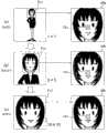
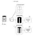
图4为表示学习过程和录象过程的例子的概念图。如图4(a)所示,在对人物进行动画摄影时,在学习过程中,预先设定目标区域TA1(图中的人物的脸),将摄影机CA的光轴朝向该目标区域TA1,进行光学变焦。然后,如图4(b)所示,进入到录象过程中。在此,由于人物虽然多少有一点活动,但是几乎为静止状态,因此能够对录象的被摄物施行学习过程。这有望提高高解像度化的质量。当然,未必一定要对例如只发生一次的现象,以这样的顺序来执行过程。此时,在进行了录象过程之后,如果在时间上还有富余的话,就可执行学习过程。并且,还能够考虑同时进行两个过程,以后再对这种情况加以说明。Fig. 4 is a conceptual diagram showing an example of a learning process and a recording process. As shown in Figure 4(a), when performing animation photography on a person, in the learning process, the target area TA1 (the face of the person in the figure) is preset, and the optical axis of the camera CA is directed towards the target area TA1 to perform optical zoom. Then, as shown in Fig. 4(b), enter into the video recording process. Here, the learning process can be performed on the subject of the video because the person moves a little, but is almost still. This is expected to improve the quality of high-resolution. Of course, it is not necessary to execute the processes in this order for phenomena that occur only once, for example. At this time, after the video recording process is performed, if there is still time left, the learning process can be performed. Furthermore, it is also conceivable to perform two processes simultaneously, and this case will be described later.
图5为表示本实施例中的学习过程的流程图。在图5中,摄影者设定目标区域(S501),摄影机CA的光学变焦按照摄影者的指示同步工作(S502)。由此,取得目标区域的高解像度图像和低解像度图像。具体地说,生成可见光图像和光谱图像(S503、S504)。这里,可见光图像为与人的视觉特性一致的彩色图像和单色图像,光谱图像为用具有狭窄带域(band)特征的过滤器将彩色成分分光之后的信息,用于更有效地识别为被摄物的特性的材质。然后,将可见光图像转换为纹理特征量,在目标区域中使高解像度纹理特征量和低解像度纹理特征量的对应关系参数化(S506)。在本案说明书中,同时将该参数化的过程称为学习。FIG. 5 is a flowchart showing the learning process in this embodiment. In FIG. 5, the photographer sets the target area (S501), and the optical zoom of the camera CA works synchronously according to the photographer's instruction (S502). Thus, a high-resolution image and a low-resolution image of the target area are obtained. Specifically, a visible light image and a spectral image are generated (S503, S504). Here, the visible light image is a color image and a monochrome image consistent with human visual characteristics, and the spectral image is the information obtained by separating the color components with a filter having a narrow band characteristic, and is used to more effectively identify the The material of the characteristics of the subject. Then, convert the visible light image into a texture feature, and parameterize the corresponding relationship between the high-resolution texture feature and the low-resolution texture feature in the target area (S506). In this case specification, the process of parameterization is also called learning.
图6为表示将利用小波转换进行的多重解像度解析的方法,作为将图像转换为纹理特征量向量的手法的一个例子。在图6中,使用了3阶段比例缩放(scale)的小波(wavelet)转换。在第一阶段(比例缩放)中,通过X、Y方向的小波转换将输入图像IN分解为与输入图像IN尺寸相同的4个成分的图像H1H1、H1L1、L1H1、L1L1。在第二阶段(比例缩放)中,虽然进一步分解已被分解的4个成分中的X、Y双方向的高频成分H1H1以外的成分,但仅将L1L1再次分解成X、Y这两个方向,将H1L1和L1H1仅朝一个方向分解,合计为8个成分。并且,在第三阶段(比例缩放)中,分解H2H2以外的成分,同样仅使L2L2朝X、Y这两个方向分解,其它的朝一个方向分解,使其分解为12个成分。在此,能够通过以后的合成来生成用增加比例缩放的方法被再次分解为两个、4个的(图中用虚线表示)。如图7所示,通过这样的小波转换的分解,来将输入图像IN的各像素分解成16次元的成分。将这些16个成分汇在一起的向量是像素位置PP中的纹理特征量TF1。FIG. 6 shows a method of multi-resolution analysis using wavelet transform as an example of a method of converting an image into a texture feature vector. In FIG. 6, a wavelet transformation with 3 stages of scaling is used. In the first stage (scaling), the input image IN is decomposed into 4 component images H1H1, H1L1, L1H1, L1L1 of the same size as the input image IN by wavelet transformation in X and Y directions. In the second stage (scaling), although the components other than the high-frequency components H1H1 in the X and Y directions are further decomposed among the four components that have been decomposed, only L1L1 is decomposed into the two directions of X and Y again. , decompose H1L1 and L1H1 in only one direction, totaling 8 components. In addition, in the third stage (scaling), components other than H2H2 are decomposed, similarly only L2L2 is decomposed in the two directions of X and Y, and the others are decomposed in one direction to decompose into 12 components. Here, it can be generated by subsequent synthesis that is decomposed into two and four again by increasing scaling (indicated by a dotted line in the figure). As shown in FIG. 7 , each pixel of the input image IN is decomposed into 16-dimensional components by such wavelet transform decomposition. A vector combining these 16 components is the texture feature amount TF1 at the pixel position PP.
如上所述,分别将低解像度图像和高解像度图像转换成纹理特征量,学习它们之间的相互关系,生成分析码本(code book)和再生码本。即,在阿部淑人、菊池久和、佐佐木重信、渡边弘道、齐藤义明的“使用了多重解像度向量量子化的轮廓协调”电子信息通讯学会论文杂志Vol.J79A1996/5(1032—1040页)等中对这样的处理进行了详细地说明,在此,将该详细说明加以省略。此时,步骤S506中的参数化相当于生成分析码本及再生码本。As described above, the low-resolution image and the high-resolution image are respectively converted into texture feature quantities, the correlation between them is learned, and an analysis codebook (codebook) and a reproduction codebook are generated. That is, in Abe Yoshito, Kikuchi Hisawa, Sasaki Shigenobu, Watanabe Hiromichi, Saito Yoshiaki "Contour Coordination Using Multi-Resolution Vector Quantization" Journal of Electronic Information and Communication Society Vol.J79A1996/5 (1032-1040 Such processing is described in detail in pp. 10-19, etc., and the detailed description thereof is omitted here. In this case, the parameterization in step S506 corresponds to generating an analysis codebook and a reproduced codebook.
其次,在步骤S507中,从光谱图像中求出目标区域的被摄物特性,将其作为学习结束材质记录下来。具体地说,如图8所示,通过特征向量量子化处理将用低解像度取得的光谱图像的彩色信息生成为一个特征量,将其作为代表一个固有材质的代表向量记录下来。Next, in step S507, the object characteristics of the target area are obtained from the spectrum image, and recorded as the learning-finished material. Specifically, as shown in FIG. 8 , the color information of the spectral image obtained with a low resolution is generated as a feature quantity through eigenvector quantization processing, and is recorded as a representative vector representing an inherent material.
在步骤S508中,当对其它目标区域进行学习时,又一次设定目标区域,反复进行步骤S503~S507。当不是对其它目标区域进行学习时,结束图像的取得(学习过程)。In step S508, when learning another target area, the target area is set again, and steps S503-S507 are repeated. When learning is not performed on other target regions, image acquisition (learning process) ends.
在此,用图9对目标区域和光学变焦的关系加以说明。Here, the relationship between the target area and the optical zoom will be described using FIG. 9 .
图9(a)为变焦之前的状态,用广角拍摄成为被摄物的人物。此时,如图4(a)所示,在将目标区域设定为人物的脸部时,设定以目标区域为中心的基准帧(reference frame)FL1。该基准帧FL1在光学变焦的最大倍率中相当于将画面摄满的狭窄视角的范围。纹理特征量等图像处理是在将该基准帧FL1正规化为光学变焦的最大倍率的图像尺寸的基础上执行的。FIG. 9( a ) is a state before zooming, and a person who becomes a subject is photographed at a wide angle. At this time, as shown in FIG. 4( a ), when the target area is set as the face of a person, a reference frame (reference frame) FL1 centered on the target area is set. The reference frame FL1 corresponds to a range of a narrow angle of view that fills the screen at the maximum magnification of the optical zoom. Image processing such as texture feature data is performed by normalizing the reference frame FL1 to the image size of the maximum magnification of the optical zoom.
因此,摄影者朝着目标区域即基准帧FL1让高解像度图像取得过程启动。与此同步进行光学变焦。图9(b)为表示光学变焦的途中过程的图,对基准帧FL1区域继续变焦。然后,最终能够获得如图9(c)所示的那样的在整个用最大倍率进行光学变焦的基准帧FL1内的高解像度的狭窄视角的图像。Therefore, the photographer starts the high-resolution image acquisition process toward the target area, that is, the reference frame FL1. Optical zooming is performed in synchronization with this. FIG. 9( b ) is a diagram showing the progress of the optical zoom, and zooming continues on the area of the reference frame FL1 . Then, finally, as shown in FIG. 9( c ), a high-resolution image with a narrow viewing angle within the entire reference frame FL1 optically zoomed at the maximum magnification can be obtained.
IMa、IMb、IMc分别为图9(a)~图9(c)的状态中的基准帧FL1内的图像,为将尺寸正规化之后的图像。由于在图像IMa中,对不充分的像素尺寸进行数码插补,仅让图像尺寸一致,因此产生了大幅度的模糊不清。同样,虽然光学变焦途中的图像IMb的解像度高于图像IMa,但是因插补的影响,因此多少有些模糊也是没有办法的。并且,利用光学最大变焦倍率拍摄的图像IMc为鲜明的高解像度图像。因而,对于为基准帧FL1的中心部的目标区域TA1,即使在图像IMa中呈现出非常模糊的纹理,但在图像IMb中纹理处于两者之间,在图像IMc中为非常鲜明的纹理。在图5的步骤S506中,使这些纹理特征之间的对应关系作为使用了小波转换的多重解像度向量之间的关系来参数化。IMa, IMb, and IMc are images in the reference frame FL1 in the states of FIGS. 9( a ) to 9 ( c ), respectively, and are images whose sizes have been normalized. In the image IMa, the insufficient pixel size is digitally interpolated, and only the image size is made uniform, resulting in significant blurring. Similarly, although the resolution of the image IMb during optical zooming is higher than that of the image IMa, it is unavoidable that it is somewhat blurred due to the influence of interpolation. In addition, the image IMc captured with the optical maximum zoom factor is a sharp high-resolution image. Therefore, even if the target area TA1 at the center of the reference frame FL1 appears very blurry in the image IMa, the texture is in between in the image IMb and very clear in the image IMc. In step S506 of FIG. 5 , the correspondence relationship between these texture features is parameterized as a relationship between multi-resolution vectors using wavelet transform.
其次,对参数化加以说明。在此,参数化是通过向量量子化、和分析码本及再生码本这两种对应表的生成来实现的。Next, the parameterization is explained. Here, parameterization is realized by vector quantization and generation of two types of correspondence tables, an analysis codebook and a reproduction codebook.
对每个100像素的像素位置,将模糊图像和鲜艳化图像转换为多重解像度向量。使其为U1~U100、V1~V100。由于在向量U1~U100与向量V1~V100之间存在有像素位置相同的关系,因此只要将码本生成为在输入了U时,输出对应的V即可。不过,实际上,通过向量量子化将多重解像度向量分类为代表向量。For each pixel location of 100 pixels, convert the blurred and brightened images into multiresolution vectors. Make it U1~U100, V1~V100. Since there is a relationship that the pixel positions are the same between the vectors U1 to U100 and the vectors V1 to V100, it is only necessary to generate the codebook so that when U is input, the corresponding V is output. In practice, however, multi-resolution vectors are classified as representative vectors by vector quantization.
在图10的例子中,向量U被量子化为UA和UB两种,向量V被量子化为VA和VB两种。解析码本和再生码本的量子化索引(quantizationindexes)意味着标注在这些被量子化的向量集合中的号码。并且,翻开码本是指一输入向量号码V,就会获得作为被量子化的向量集合的号码的1、2这样的号码。并且,对量子化集合VA附带有代表向量Z1,对量子化集合VB附带有代表向量Z2。这些代表向量是通过求出属于量子化集合中的向量的平均值和代表值等方法计算的。In the example of FIG. 10, the vector U is quantized into two types UA and UB, and the vector V is quantized into two types VA and VB. The quantization indexes (quantization indexes) of the parsed codebook and the reproduced codebook mean the numbers marked in these quantized vector sets. In addition, opening the codebook means that when the vector number V is input, numbers such as 1 and 2 are obtained as numbers of quantized vector sets. Furthermore, a representative vector Z1 is attached to the quantization set VA, and a representative vector Z2 is attached to the quantization set VB. These representative vectors are calculated by finding the average and representative values of the vectors belonging to the quantized set, etc.
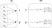
其次,如图11所示,从向量号码中生成输出量子化索引(1或2)的解析码本CB1、和输入量子化索引(1或2)且输出再生向量的再生码本CB2。能够通过将藉此方法生成的解析码本和再生码本结合起来使用,来将模糊图像的多重解像度向量转换成鲜艳图像的多重解像度向量。Next, as shown in FIG. 11 , an analysis codebook CB1 that outputs a quantization index (1 or 2) and a reproduction codebook CB2 that inputs a quantization index (1 or 2) and outputs a reproduction vector are generated from the vector number. It is possible to convert the multi-resolution vectors of blurred images into multi-resolution vectors of vivid images by using the analytical codebook generated in this way and the reproduced codebook in combination.
在上述例子中,将一对低解像度图像和高解像度图像分别量子化来进行学习,其次,对利用低解像度图像到高解像度图像的多个图像取样集合来进行学习的例子加以说明。In the above example, learning is performed by quantizing a pair of low-resolution images and high-resolution images respectively. Next, an example of learning using a plurality of image sample sets from low-resolution images to high-resolution images will be described.
例如,当在后述的录象过程中顺利地进行了光学变焦时,为了进行高解像度显示,必须要对所有如从1×1到2×2、3×3、4×4…那样地进行了变焦的过程中的图像都进行高解像度化。例如,为了将这样的变焦图像以高解像度化显示在具有两倍像素数的显示装置中,必须要对变焦过程中的所有图像执行2×2高解像度化。For example, when the optical zoom is successfully performed in the video recording process described later, in order to perform high-resolution display, it is necessary to perform zooming on all zooms such as from 1×1 to 2×2, 3×3, 4×4… Images during zooming are all high-resolution. For example, in order to display such a zoomed image at high resolution on a display device having twice the number of pixels, it is necessary to perform 2×2 high resolution on all images during zooming.
如图12所示,为了实施上述2×2高解像度化的学习的一对图像是对于光学变焦率为1×1的图像IM1,光学变焦率为2×2的图像IM2,对于光学变焦率为2×2的图像IM2,光学变焦率为4×4的图像IM4。作为学习样本,一般必须到解像度化的倍率M、和被拍摄的图像自身的光学变焦倍率N的积为M×N的光学变焦图像为止。不过,个别执行这些学习会成为很大的负担,另外,在显示过程中将使用不同的高解像度化参数,而产生本来光滑的光学变焦映像在每个帧变动的可能性。As shown in FIG. 12, a pair of images for carrying out the above-mentioned 2×2 high-resolution learning is an image IM1 with an optical zoom ratio of 1×1, an image IM2 with an optical zoom ratio of 2×2, and an image with an optical zoom ratio of 2×2. The image IM2 is 2×2, and the image IM4 is 4×4 with optical zoom ratio. As a learning sample, it is generally necessary to obtain an optical zoom image in which the product of the resolution magnification M and the optical zoom magnification N of the captured image itself is M×N. However, performing these studies individually will become a heavy burden, and different high-resolution parameters will be used in the display process, resulting in the possibility that the original smooth optical zoom image will vary from frame to frame.
所以,在学习过程中,施行M×N倍为止的光学变焦,且将这些尺寸的图像正规化,求出多重解像度向量的集合,来生成共同的分析码本CB。在码本CB中,使Z1~Z3为图像IM1的量子化向量,使Z2~Z6为图像IM2的量子化向量,使Z5~Z9为止为图像IM4的量子化向量。并且,为了生成再生码本,根据成为一对的各图像的像素对应来决定分析码本CB内的对应。根据对该对的学习,来在图像IM1时生成Z1与Z2的对应,Z2与Z3的对应,Z3与Z4的对应,由此生成再生码本。Therefore, in the learning process, an optical zoom of up to M×N times is performed, images of these sizes are normalized, a set of multiple resolution vectors is obtained, and a common analysis codebook CB is generated. In the codebook CB, Z1 to Z3 are quantized vectors of the image IM1, Z2 to Z6 are quantized vectors of the image IM2, and Z5 to Z9 are quantized vectors of the image IM4. Then, in order to generate the reproduced codebook, the correspondence in the analysis codebook CB is determined based on the correspondence between the pixels of each pair of images. Based on the learning of the pair, the correspondence between Z1 and Z2, the correspondence between Z2 and Z3, and the correspondence between Z3 and Z4 are generated in the image IM1, thereby generating a reproduced codebook.
如上所述,高解像度化用的特征向量从一连串的光学变焦图像群IM1~IM4中一次性生成。因而,虽然有可能限制所用的量子化向量的变化,但由于提高了利用的向量的共通性,因此能够维持动画平稳的光学变焦,同时,实现高解像度化。另外,为了在变焦动画中实现更加平稳的高解像度化,也可以采用在时间上对分散的再生码本进行插补的方法。As described above, the eigenvectors for high-resolution are generated at once from a series of optical zoom image groups IM1 to IM4. Therefore, although it is possible to limit the variation of the quantization vectors used, since the commonality of the vectors used is increased, it is possible to maintain smooth optical zooming of moving pictures and at the same time achieve high resolution. In addition, in order to achieve a more stable increase in resolution in zoom animation, a method of interpolating temporally dispersed reproduced codebooks may also be employed.
图13为表示本实施例中的录象过程的流程图。在录象过程中,如图4(b)所示,例如,对处于动态中的人物进行动画摄影,此时的视角为广视角状态到光学变焦状态这样的各种状态。在取得图像之后,与图5所示的学习过程一样,用动画帧速率进行可见光图像的生成(S601)及光谱图像的生成(S602)、和纹理特征量转换。并且,通过从光谱图像中,将光谱信息量子化,来计算出表现材质的被摄物特性(S603),参照已被记录的学习结束材质,对图像区域进行分割,对同一材质区域进行加标(labeling),来生成材质图像(S604)。并且,将该材质图像、和为被录象的可见光图像的录象动画记录下来,存储起来,且传送出去(S605)。Fig. 13 is a flow chart showing the video recording process in this embodiment. In the video recording process, as shown in FIG. 4( b ), for example, animation photography is performed on a moving character, and the viewing angles at this time are various states from wide viewing angle state to optical zoom state. After acquiring the image, similar to the learning process shown in FIG. 5 , generation of visible light image ( S601 ), generation of spectral image ( S602 ), and texture feature conversion are performed at the animation frame rate. And, by quantizing the spectral information from the spectral image, calculate the subject characteristics of the material (S603), refer to the recorded material of the end of learning, divide the image area, and add the same material area (labeling) to generate a material image (S604). And, the texture image and the video animation of the video-recorded visible light image are recorded, stored, and transmitted (S605).
图14为材质图像的一个例子的模式图,在图4的状况中,为将人物脸部的皮肤部分作为目标区域学习、记录时的材质图像的例子。在图14的图像中,将标注了斜线的部分识别为与皮肤同质的材质区域。FIG. 14 is a schematic diagram of an example of a texture image. In the situation of FIG. 4 , it is an example of a texture image when learning and recording the skin part of a person's face as a target area. In the image of FIG. 14 , the hatched portion is identified as a material area homogeneous to the skin.
图15为示意地表示在本实施例中所存储/所传送的图像文件格式图。在图15中,1501为表示在录象过程中所记录的原图像的图像数据,这里,为辉度图像或RGB图像的活动图像,将二次元的位置和时间的函数表示为I(x、y、t)。与用现有的动画摄影机功能所取得的图像并没有什么特别的不同,例如,也可以是DV和MPEG等被压缩的活动图像文件。1502为表示在录象过程中所生成的、根据原图像中的被摄物特性所分割的区域的区域分割图像数据,这也作为动画表示为Mi(x、y、t)。在图15的图像数据1502中,仅表示了与人物的皮肤材质相同的材质的区域,在记录有多种材质时,为表示已被学习记录的各材质的区域和未学习的区域的图像。1503为在图像学习过程中对每个被摄物特性所学习的高解像度化参数数据,包含上述分析码本AC(Mi)及再生码本SC(Mi)。Fig. 15 is a diagram schematically showing the format of an image file stored/transmitted in this embodiment. In Fig. 15, 1501 represents the image data of the original image recorded in the video recording process, here, it is a moving image of a luminance image or an RGB image, and the function of the position and time of the two-dimensional element is expressed as I(x, y, t). There is no special difference from images obtained by existing video camera functions, for example, compressed video files such as DV and MPEG may also be used. 1502 is area division image data representing areas divided according to the characteristics of the subject in the original image generated during video recording, which is also expressed as Mi(x, y, t) as animation. In the
即可以在摄影机装置中,将图15所示的信息一起记录在存储器卡等中,也可以经由网络进行传送。并且,也可以将图15的信息全部定义为一个图像文件,将其传送到显示系统。这样一来,没有将数据量非常多的高解像度动画照原样传送出去的情况,能够在显示侧实现自由自在的高解像度化。That is, in the camera device, the information shown in FIG. 15 may be recorded together on a memory card or the like, or may be transmitted via a network. Also, all the information in FIG. 15 may be defined as one image file and transmitted to the display system. In this way, it is possible to achieve free high-resolution on the display side without transferring a high-resolution video with an extremely large amount of data as it is.
图16为表示本实施例中的在高解像度化过程即显示侧的处理的流程图。首先,接收图15那样的存储传送数据,取得记录动画(活动图像1501)、材质区域分割图像1502及高解像度化参数(参数文件1503)(S701)。然后,取得为了依次处理的记录动画的一个帧的各像素(S702)。参照材质区域分割图像,判断该像素对应于被学习的哪一种材质(S703)。当判断为对应于学习结束材质时,将像素转换为纹理特征量(S704),使用对应于纹理特征量的材质所涉及的高解像度化参数,生成高解像度纹理特征量(S705)。然后,进行将高解像度纹理特征转换为图像的相反转换(S706)。这只要进行图6及图7所述的处理的相反转换即可。另一方面,对于被判断为不是对应于学习结束材质的图像,进行现有的插补处理(S707)。结果是显示高解像度动画。FIG. 16 is a flowchart showing processing on the display side in the high-resolution process in this embodiment. First, the stored transfer data as shown in FIG. 15 is received, and the recorded video (moving image 1501), texture region divided
(第三实施例)(third embodiment)
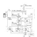
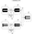
图17为本发明的第三实施例所涉及的图像处理装置,为表示将本发明应用在视频电影摄影机(video movie camera)中的例子的方块图。图17的图像处理装置包括变焦镜头301、变焦控制部302、可见光/光谱摄影部303、生成由被摄物的光谱信息构成的作为第三图像的光谱图像的光谱图像生成部304、可见光图像生成部305、材质图像生成部306、纹理特征转换部307、学习结束区域分割部308、显示器等作为显示部的学习结束区域显示部309、材质区域分割图像记录部310、纹理特征学习部311、高解像度化参数记录部312、学习按钮313、记录按钮314及图像记录部315。由变焦镜头301、变焦控制部302、可见光/光谱摄影部303、光谱图像生成部304及可见光图像生成部305构成取得部,该取得部构成为能够对于被摄物的目标区域取得解像度不同的第一及第二图像、和表示被摄物特性的作为第三图像的光谱图像。由纹理特征转换部307及纹理特征学习部311构成规则生成部,该规则生成部从取得部取得的第一及第二图像中生成使该第一及第二图像相互对应的解像度转换规则。由材质图像生成部306及学习结束区域分割部308构成区域分割图像生成部,该区域分割图像生成部从光谱图像中生成根据被摄物特性进行了区域分割的区域分割图像。FIG. 17 is an image processing device according to a third embodiment of the present invention, and is a block diagram showing an example of applying the present invention to a video movie camera. The image processing device in FIG. 17 includes a
摄影者在动画记录过程之前,执行图像学习过程。首先,决定被摄物的目标区域,将摄影机朝着所对应的地方,按下学习按钮313。在收到该信号之后,变焦控制部302让变焦镜头301动作,可见光/光谱摄影部303取得目标区域的低解像度图像和高解像度图像。通过光谱图像生成部304及可见光图像生成部305将所取得的图像分为光谱图像、和解像度不同的作为第一及第二图像的可见光图像。纹理特征转换部307将可见光图像转换为纹理特征,材质图像生成部306从光谱图像中生成材质图像。这里的材质图像是指根据材质这样的被摄物特性而被量子化识别的图像。然后,学习结束区域分割部308进行材质图像的区域分割,生成材质区域分割图像。将所生成的材质区域分割图像显示在学习结束区域显示部309中。The photographer performs an image learning process prior to the animation recording process. First, determine the target area of the subject, point the camera towards the corresponding place, and press the
图18为学习结束区域显示部的显示例。如图18所示,将用材质对被摄物图像进行了分割的材质区域分割图像显示在画面中央。并且,在画面左上方显示有表示学习结束区域的凡例的窗口WD1,在画面右下方显示有表示未学习区域的凡例的窗口WD2。从窗口WD1得知M1(皮肤部)、M2(头发部)、M3(杯子)及M4(皮鞋)都已学习结束。并且,白色区域为未学习区域。Fig. 18 is a display example of a learning end area display unit. As shown in FIG. 18 , a texture region divided image obtained by dividing the subject image by texture is displayed in the center of the screen. In addition, a window WD1 showing examples of learning completed areas is displayed on the upper left of the screen, and a window WD2 indicating examples of unlearned areas is displayed on the lower right of the screen. Learn from window WD1 that M1 (skin part), M2 (hair part), M3 (cup) and M4 (leather shoes) have all been studied. And, the white area is the unlearned area.
看到了这样的显示的摄影者对学习按钮313进行操作,例如,在为未学习区域的被摄物的服装上设定目标区域TA3,执行学习。即,学习结束区域显示部309具有辅助摄影者确认未学习区域,设定其它目标区域的作用。来自学习开始按钮313的信号还被传送到纹理特征学习部311和高解像度化参数记录部312中,如上述实施例所述地那样生成纹理特征之间的高解像度化参数,且将其记录下来。图19为学习之后的学习结束区域显示部309的显示例。即,学习M5(服装部),未学习区域仅为背景部分。The photographer who sees such a display operates the
并且,摄影者从学习结束区域显示部309的显示中确认已学习的材质分布在图像内的哪一区域,如果,错误的区域被作为同一材质加标时,可以再次设定目标区域,进行重新学习。例如,当将人物脸部的皮肤部分设定为目标区域时,如图18所示,手脚的皮肤区域被识别为同一性质。此时,当摄影者判断出脸部的皮肤和手脚的皮肤的纹理不同时,只要调整识别阈值等,使脸部和手脚被识别为不同的区域即可。In addition, the photographer confirms in which area of the image the learned material is distributed from the display of the learning end
在学习过程之后,摄影者为了执行录象过程,按下记录按钮314。使来自可见光图像生成部305的动画记录在图像记录部315中。此时,最好进行适当的图像压缩。After the learning process, the photographer presses the
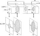
图20为表示可见光/光谱摄影部303的结构例的图。在图20的结构中,使用3CCD方式的通常视频电影中的彩色图像摄影用的光学类、和将摄影元件改良之后的6个频带(band)的可进行光谱图像摄影的元件。在3CCD方式中,通过二向色棱镜321将波长带分为红色、绿色、蓝色,将CCD元件分配给各彩色频带。在这点上是相同的,在图20的结构中不同之处在于:在各CCD元件内排列有不同的两种透过带CCD元件。即,对红色波长区域CCD322排列用波长区域1及波长区域2表示的CCD元件,对绿色波长区域CCD323排列用波长区域3及波长区域4表示的CCD元件,对蓝色波长区域CCD324排列用波长区域5及波长区域6表示的CCD元件。能够通过来自这些CCD322、323、324的输出的插补信号处理,用与元件像素数相同的图像尺寸生成6个频带的像素浓度的光谱图像IMG1、和由3个频带的像素浓度RGB构成的可见光图像IMG2。FIG. 20 is a diagram showing a configuration example of the visible light/
图21为表示光谱图像中各频带的波长感度的坐标图。6个频带分别在大约380nm~780nm的可见区域中,具有图21所示的狭窄波长区域。因此,与3个频带相比,能够准确地取得R(λ)那样的光谱信息。从而,能够对不依存与照明的被摄物更准确地求出固有的光谱反射率。另外,即使对在3个频带的彩色图像中被观测为同一绿色的被摄物,也能够细致地识别出是植物,还是绿色的纸那样的材质的不同。而且,为了实现材质的识别,并不一定要将波长区域位置限定为可见区域,对近红外区域设定频带也非常有效。并且,能够例如用数式【1】那样的公式简单地实现从6个频带图像来生成可见光图像的功能。Fig. 21 is a graph showing the wavelength sensitivity of each frequency band in a spectral image. Each of the six frequency bands has a narrow wavelength region as shown in FIG. 21 in the visible region of approximately 380 nm to 780 nm. Therefore, spectral information such as R(λ) can be acquired more accurately than the three frequency bands. Therefore, it is possible to more accurately obtain the intrinsic spectral reflectance of a subject that does not depend on illumination. In addition, even for a subject observed as the same green color in the color images of the three frequency bands, it is possible to finely distinguish whether it is a plant or a difference in material such as green paper. Furthermore, in order to realize material identification, it is not necessary to limit the position of the wavelength region to the visible region, and it is also very effective to set the frequency band for the near-infrared region. In addition, the function of generating a visible light image from six frequency band images can be easily realized, for example, by using an equation such as equation [1].
R=band(1)+band(2)R=band(1)+band(2)
G=band(3)+band(4)G=band(3)+band(4)
B=band(5)+band(6)B=band(5)+band(6)
(第四实施例)(fourth embodiment)
图22为本发明的第四实施例所涉及的图像处理装置,为表示摄影者不进行操作,自动学习被摄物的目标区域各部来进行摄影的摄影机结构的方块图。在图22中,对与图17一样的结构要素标注同一符号,在此,对其详细说明加以省略。与图17的不同之处在于:包括光轴可变焦机构401、光轴可变焦控制部402、摄影机工作程序设定部403、摄影机工作显示部404、摄影机工作程序存储部405、照明推定部406及录象许可部407。由光轴可变焦机构401、光轴可变焦控制部402、可见光/光谱摄影部303、光谱图像生成部304及可见光图像生成部305构成取得部。22 is a block diagram showing the configuration of a camera that automatically learns each part of a target area of a subject without manipulation by a photographer in an image processing device according to a fourth embodiment of the present invention. In FIG. 22, the same components as those in FIG. 17 are denoted by the same reference numerals, and detailed description thereof will be omitted here. The difference from FIG. 17 is that it includes an optical
图23为表示光轴可变焦机构的一个例子的概念图。在图23的结构中,使用了作为光学斑点校正用的技术的移轴镜头机构(例如,参照特开平11—344669号等)。从物体一侧,包括:具有正折射本领且相对于像面固定的第一镜头群411;具有负折射本领且具有在光轴上移动来改变倍率的作用的第二镜头群412;固定在像面的具有正折射本领的第三镜头群413;固定在像面的具有负折射本领的第四镜头群414;使因第二镜头群412的移动及物体的移动而变动的像面与标准面保持一定距离而在光轴上移动的具有正折射本领的第五镜头群415;以及由电磁石等构成移轴镜头机构416。光轴的变化是通过用移轴镜头机构416让第三镜头群413在与光轴垂直的方向上移动进行的,变焦功能是通过第二镜头群412及第五镜头群415的移动作用进行的。通过此机构能够将为摄影的视角中的一定部位的目标区域向光轴中心移动,同时能够进行光学变焦。这样一来,即使不移动摄影机本身,也能够对全部的画面内的目标区域自动地执行光学变焦。FIG. 23 is a conceptual diagram showing an example of an optical axis zoom mechanism. In the configuration of FIG. 23, a shift lens mechanism which is a technique for correcting optical speckle is used (for example, refer to JP-A-11-344669, etc.). From the object side, it includes: a
在摄影机工作显示部404设置有触摸屏等操作装置,以便能够进行指定目标区域等的操作。The camera
摄影者一边观察摄影机工作显示部404的显示,一边决定摄影机的录象视角。在本实施例中,由于在学习过程中,摄影机利用镜头机构,自动地进行目标的学习,因此必须在学习期间,事先固定好摄影机的位置。从这方面出发,最好在记录过程中也将摄影机视角和方向固定下来。The photographer determines the video recording angle of view of the camera while viewing the display of the camera
首先,在学习过程中,用图像上的坐标指定摄影范围和被摄物中的多个不同材质的目标区域。这里所说的指定不同材质的目标区域是指通过指定映在画面上的被摄物的图像区域来指定进行学习的被摄物的材质的意思。被指定的内容在摄影机工作程序设定部403中被程序化,作为将变焦和由光轴变化引起的平移动作组合在一起的图像学习过程和录象过程的控制程序存储在摄影机工作程序存储部405中。First, in the learning process, the coordinates on the image are used to specify the shooting range and target areas of multiple different materials in the subject. The designation of a target region of a different texture means designating the texture of the subject to be learned by designating the image region of the subject reflected on the screen. The specified content is programmed in the camera operation
在图像学习过程中,光轴可变焦控制部402按照存储在摄影机工作程序存储部405中的程序来自动地控制光轴可变焦机构401。并且,一边对被摄物的任意位置调整光轴,进行光学变焦,一边对多个目标区域进行高解像度图像的取得和材质的学习。During image learning, the optical axis
在录象过程中,按照存储在摄影机工作程序存储部405中的程序,自动地进行规定时间的动画摄影。此时,摄影机的视角和方向基本上都固定在支架上。During the recording process, according to the program stored in the camera operation
照明推定部406通过对整个图像进行的图像处理检测出被摄物的照明环境的变化,判断再次进行学习的必要性。这里的学习包括解像度转换规则的生成。并且,当被判断为需要进行再次学习时,摄影机通过例如摄影机工作显示部404,将此信息通知给摄影者。The
并且,录象许可部407具有在学习还没有结束的情况下,就想进行录象和摄影时,或者在因照明条件发生变化而需要再次进行学习,但却没有进行时,不允许录象和摄影,不让录象按钮和快门工作的机构。即,本实施例所涉及的摄影机具有在需要生成解像度转换规则时禁止摄影的机构。从而,能够未然防止高解像度化的失败。And video
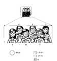
作为本实施例所涉及的摄影机的典型用途,能够想到图24(a)那样的对在舞台上的很多人进行合唱来进行录象的情况。此时,至今为止,是通过摄影者自身所具有的摄影技巧对各成员的脸部进行特写的。但是,此时会产生摄影者所喜欢的人物和团体的中心人物被特写的比率较高,引起其它成员不满的可能性。并且,如果不是熟练的摄影师的话,则不能较好地对全景和个人的特写进行摄影,而且必须对摄影具有相当高的集中力。而在使用本实施例所涉及的摄影机时,具有这样的优点:摄影者不必考虑摄影技巧,只要将全景拍摄下来即可,能够通过摄影之后的编辑自由自在地进行图像的高解像度化,还能够很容易地获得全部成员的特写。As a typical application of the video camera according to this embodiment, a case where a large number of people on a stage are chorused and videotaped is conceivable as shown in FIG. 24( a ). At this time, up to now, the faces of each member have been taken close-up by the photographer's own photography skills. However, at this time, the person whom the photographer likes and the central person of the group may be featured at a high rate, which may cause dissatisfaction among other members. In addition, if you are not a skilled photographer, you cannot take pictures of panoramas and personal close-ups well, and you must have a relatively high concentration on photography. And when using the video camera involved in this embodiment, there is such an advantage: the photographer does not need to consider the photography skills, as long as the panorama is taken, the high-resolution image can be freely carried out through the editing after the photography, and the Get close-ups of all members easily.
在图24(a)中,为了对作为被摄物的舞台上的合唱团进行摄影,而将摄影机CA和摄影机支架BS设置在例如观览席中。用图25的流程图对此时的学习过程加以说明。In FIG. 24( a ), in order to photograph a choir on a stage as a subject, a camera CA and a camera stand BS are installed, for example, in a viewing booth. The learning process at this time will be described using the flow chart of FIG. 25 .
首先,摄影者一边从整个合唱团的映像中指定对特定位置进行光学变焦,观察摄影机工作显示部404的显示,一边通过手动指定不同材质的目标区域(S801)。图24(b)为指定与此时的显示的材质不同材质的目标区域的一个例子。在图24(b)中,分别将个人的脸部区域(1)、黑发(2)、茶发(3)、数据(4)及乐谱表面的纸(5)指定为不同材质的目标区域。另外,这些区域是为了学习不同材质而指定的,不需要有关它们位置的信息。First, the photographer designates an optical zoom to a specific position from the image of the entire choir, and observes the display of the camera
然后,摄影机生成材质图像(S802),从画面内将所有的被摄物特性(材质)与被指定的不同材质的目标区域相同的区域自动地检测出来(S803)。并且,用光轴可变焦机构对不同材质的目标区域进行光学变焦(S804),以后再对该不同材质的目标区域自动地进行学习(S503~S507)。这里的处理与第二实施例一样,对其详细情况加以省略。在对所有的不同材质的目标区域进行了学习之后(在S805中,为“No”的情况),结束学习过程。Then, the camera generates a texture image (S802), and automatically detects all areas in the screen where the characteristics (material) of the subject are the same as the specified target area of a different texture (S803). In addition, the optical axis zoom mechanism is used to optically zoom the target area of different materials (S804), and then the target area of different materials is automatically learned (S503-S507). The processing here is the same as in the second embodiment, and its details are omitted. After all target areas of different materials are learned (in the case of "No" in S805), the learning process ends.
图26为表示学习过程和录象过程的时间关系的时序图。图26(a)表示进行动画录象的情况。在要开始合唱之前,结束目标学习(期间t1),对合唱进行动画录象(期间t2)。在录象时不需要特别的摄影技巧,只要对全景进行摄影即可。并且,例如,当舞台上的照明发生变化时,由于通过光谱信息得到的学习内容变得不恰当,因此有时必须再次进行学习(期间t3)。并且,也可以在每次规定时间一经过时,就进行学习。此时,摄影机通过照明推定部406检测出条件的变化,向摄影者发出必须再次进行学习的指示。这时,最好一边进行录象,一边进行目标学习,但是也可以将为了目标学习而拍摄的图像就那样代用为录象。Fig. 26 is a sequence diagram showing the temporal relationship between the learning process and the video recording process. Fig. 26(a) shows the case of video recording. Before the start of the chorus, target learning is completed (period t1), and video recording of the chorus is performed (period t2). No special photography skills are required during video recording, as long as the panorama is photographed. Also, for example, when the lighting on the stage changes, the learning content obtained from the spectral information becomes inappropriate, so learning may have to be performed again (period t3). In addition, learning may be performed every time a predetermined time elapses. At this time, the camera detects a change in conditions through the
并且,图26(b)表示拍摄合唱团的集合照片的情况。此时,利用自拍机构,在计时器工作期间,在集合的所有成员处于静止的状态下,对作为目标检测出的人物的脸部一个接一个进行光学变焦,使它们高解像度化,参数化(期间t5)。然后,拍摄所有成员的集合照片。这样一来,能够通过以后的编辑,从一张静止图像中对个人的脸部进行高解像度化。并且,在照明发生了变化时,在进行了再次学习之后,再进行静止图像的摄影。此时,只要在还没有进行学习期间,通过控制录象许可部407使其为不能摄影的状态即可。In addition, FIG. 26(b) shows a situation where a group photograph of a choir is taken. At this time, using the self-timer mechanism, during the operation of the timer, when all the members of the set are in a static state, the faces of the people detected as targets are optically zoomed one by one to make them high-resolution and parameterized ( period t5). Then, take a group photo of all members. In this way, a person's face can be high-resolution from a still image through subsequent editing. In addition, when the illumination changes, the still image is captured after performing re-learning. At this time, it is only necessary to control the video
另外,在该例子中,由于个人的脸部被认为是具有同样皮肤的材质,因此不能通过个别的手法进行高解像度化。如果,想通过个别的手法对各人的脸部进行高解像度化时,必须要想出使每个被摄物特性不同的手法,例如,各人使用具有不同特性的化妆品等之类的手法。In addition, in this example, since the individual's face is considered to have the same skin texture, it is not possible to increase the resolution by an individual method. If it is desired to increase the resolution of each person's face by an individual method, it is necessary to think of a method to make the characteristics of each subject different, for example, each person uses cosmetics with different characteristics.
(第五实施例)(fifth embodiment)
图27为本发明的第五实施例所涉及的图像处理装置,为表示摄影者不进行操作,自动学习被摄物的目标区域各部来进行摄影的摄影机结构的方块图。在图27中,对与图17及图22一样的结构要素标注同一符号。27 is a block diagram showing the configuration of a camera that automatically learns each part of a target area of a subject and shoots an image processing device according to a fifth embodiment of the present invention without manipulation by the photographer. In FIG. 27 , the same reference numerals are attached to the same components as those in FIGS. 17 and 22 .
与第四实施例的不同之处在于:没有图像学习过程和录象过程的区别,当摄影者通过与通常的电影摄影机一样的操作对着被摄物开始录象时,根据需要,用光轴可变焦机构并行地执行学习。因此,在第四实施例中,必须在学习过程期间将摄影机事先固定在支架上,但是在本实施例中,能够通过手持的摄影机自由自在地进行学习和录象。而且,在第三实施例中,摄影者有意地进行了特别的学习过程,但是在本实施例中,摄影者不需要有意地进行特别的学习过程,只要集中于录象即可。The difference with the fourth embodiment is: there is no difference between the image learning process and the video recording process. When the photographer starts video recording at the subject through the same operation as the usual movie camera, according to needs, use the optical axis The variable focus mechanism performs learning in parallel. Therefore, in the fourth embodiment, it is necessary to fix the video camera on the bracket in advance during the learning process, but in the present embodiment, learning and video recording can be freely performed by the hand-held video camera. Also, in the third embodiment, the photographer has intentionally performed a special learning process, but in this embodiment, the photographer does not need to intentionally perform a special learning process, as long as he concentrates on video recording.
在图27中,并列设置有记录部501和学习部502,由半透明发射镜503对光进行分割。透过了镜头504的光经由可见光/光谱摄影部403被输入到记录部501中,通过与第三实施例一样的工作,材质图像被记录在材质区域分割图像记录部310中,可见光图像被记录在图像记录部315中。镜头504具有变焦功能,在学习部502的输入侧设置有光轴可变焦机构401和光轴可变焦控制部402,以便在录象过程中能够另外进行学习用的变焦。由镜头504、半透明反射镜503、光轴可变焦机构401、光轴可变焦控制部402、可见光/光谱摄影部403、光谱图像生成部304及可见光图像生成部305构成取得部。In FIG. 27 , a
学习材质控制部505根据预先被程序化的学习计划(存储在工作程序设定部403中),来控制光轴可变焦控制部402及纹理特征学习部311。即,当从材质图像生成部306的输出中判断出开始了特定材质的记录时,将信号传送给光轴可变焦控制部402,让光轴可变焦机构401工作,同时,将信号传送给纹理特征学习部311,生成高解像度化参数。所生成的高解像度化参数被记录在高解像度化参数记录部312中。The learning
图28为表示本实施例中的图像录象过程的流程图。与第四实施例的图25的不同之处在于:使图像的录象与学习过程并行进行(S901)。其它步骤的处理与第四实施例一样,在步骤S801中,摄影者一边观察摄影机工作显示部404,一边用图像上的坐标选择摄影机的录象范围和其内部的多个目标区域。来设定摄影机工作程序。Fig. 28 is a flow chart showing the image recording process in this embodiment. The difference from FIG. 25 of the fourth embodiment is that the image recording and learning process are performed in parallel (S901). The processing of other steps is the same as that of the fourth embodiment. In step S801, the photographer selects the video recording range of the camera and a plurality of target areas within it by using the coordinates on the image while looking at the camera
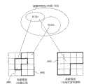
图29为表示本实施例中的低解像度图像及高解像度图像、与被摄物特性(材质)空间的关系的概念图。在图29中,为了谋求方便,使图像为用4×4像素拍摄的图像。在本实施例中,首先,取得低解像度的动画记录图像,其次,在被摄物特性空间中,将图像分割为区域AR1(对应于材质A)和区域AR2(对应于材质B)。这里,在假设已具有“学习材质A”这样的程序时,接下来,向区域AR1的位置中心部进行光轴可变焦,能够获得在同一位置为高解像度,却为狭窄视角的图像。并且,在位置彼此相同的低解像度图像的区域AR1和高解像度图像的区域AR3之间进行纹理特征的对应学习。这样一来,与上述各实施例一样,不是仅在同一材质的区域之间执行两张图像之间的学习,而且必须在同一被摄物的同一位置上执行。从而,能够实现高精度的高解像度化。FIG. 29 is a conceptual diagram showing the relationship between the low-resolution image, the high-resolution image, and the object characteristic (material) space in this embodiment. In FIG. 29 , for convenience, the image is taken with 4×4 pixels. In this embodiment, firstly, a low-resolution moving image is obtained, and secondly, in the subject characteristic space, the image is divided into a region AR1 (corresponding to texture A) and a region AR2 (corresponding to texture B). Here, assuming that the program "Learning Material A" already exists, then zooming the optical axis to the center of the area AR1 can obtain an image with a high resolution but a narrow viewing angle at the same position. Further, correspondence learning of texture features is performed between the region AR1 of the low-resolution image and the region AR3 of the high-resolution image that are located at the same position. In this way, as in the above-mentioned embodiments, the learning between two images is not only performed between regions of the same material, but also must be performed at the same position of the same subject. Therefore, it is possible to achieve high resolution with high precision.
(第六实施例)(sixth embodiment)
图30为本发明的第六实施例所涉及的图像处理装置,与第五实施例一样,为表示摄影者不进行操作,自动学习被摄物的目标区域各部来进行摄影的摄影机结构的方块图。在图30中,对与图17及图27一样的结构要素标注同一符号。Fig. 30 is a block diagram showing the configuration of a camera that automatically learns each part of the target area of the subject and takes pictures without the photographer operating the image processing device according to the sixth embodiment of the present invention, as in the fifth embodiment . In FIG. 30 , the same reference numerals are assigned to the same components as those in FIGS. 17 and 27 .
与第五实施例的不同之处在于:不使用光学变焦机构和光轴可变焦机构等,使用低解像度摄影元件603和高解像度摄影元件604来同时用相同视角拍摄被摄物。由于高解像度摄影元件一般用于静止图像的较多,不能对应于动画的帧速率的较多,因此在本实施例中,在动画录象的途中,用规定的时间来进行使用了高解像度摄影元件的学习。并且,使高解像度摄影元件为不必取得光谱信息,仅取得可见光图像即可的元件。The difference from the fifth embodiment is that the low-resolution imaging element 603 and the high-resolution imaging element 604 are used to capture a subject at the same time at the same angle of view without using an optical zoom mechanism, an optical axis zoom mechanism, and the like. Since high-resolution photographing elements are generally used for still images, and many cannot correspond to the frame rate of animation, in this embodiment, during the video recording of animation, high-resolution photography is used for a specified period of time. component learning. In addition, the high-resolution imaging element does not need to acquire spectral information, but only needs to acquire visible light images.
在图30中,并列设置有记录部601和学习部602,由半透明发射镜503对光进行分割。透过了镜头504的光经由低解像度摄影元件603作为动画被输入到记录部601中,通过与第五实施例一样的工作,材质图像被记录在材质区域分割图像记录部310中,可见光图像被记录在图像记录部315中。In FIG. 30 , a recording unit 601 and a learning unit 602 are arranged side by side, and light is divided by a
学习材质控制部505根据预先被程序化的学习计划,来控制高解像度摄影元件604及纹理特征学习部311。即,在从材质图像生成部306的输出中判断出开始了特定材质的记录时,让高解像度摄影元件604工作,用与动画同一的视角拍摄静止图像,同时,将信号传送给学习部602的纹理特征学习部311,生成高解像度化参数。将所生成的高解像度化参数记录在高解像度化参数记录部312中。The learning
图31为表示本实施例中的低解像度图像及高解像度图像、与被摄物特性(材质)空间的关系的概念图。在图31中,为了谋求方便,使低解像度图像为用4×4像素拍摄的图像,使高解像度图像为用8×8像素拍摄的图像。在本实施例中,首先,通过动画摄影取得广视角的低解像度图像,其次,在被摄物特性空间中,将图像分割为区域AR1(对应于材质A)和区域AR2(对应于材质B)。到此为止的过程与图29一样。这里,当假设已具有“学习材质A”这样的程序时,通过高解像度摄影元件604取得与低解像度图像处于同一位置,与高解像度同一视角的静止图像。并且,在位置彼此相同的低解像度图像的区域AR1和高解像度图像的区域AR4之间进行纹理特征的对应学习。因此,与上述各实施例一样,由于不是仅在同一材质的区域之间执行两张图像之间的学习,而且必须在同一被摄物的同一位置上执行,因此能够实现高精度的高解像度化。FIG. 31 is a conceptual diagram showing the relationship between the low-resolution image, the high-resolution image, and the object characteristic (material) space in this embodiment. In FIG. 31 , for convenience, the low-resolution image is an image captured with 4×4 pixels, and the high-resolution image is an image captured with 8×8 pixels. In this embodiment, firstly, a low-resolution image with a wide viewing angle is obtained through animation photography, and secondly, in the object characteristic space, the image is divided into a region AR1 (corresponding to material A) and a region AR2 (corresponding to material B) . The process up to this point is the same as that in Fig. 29 . Here, assuming that the program "Learning Material A" already exists, a still image at the same position as the low-resolution image and at the same angle of view as the high-resolution image is acquired by the high-resolution imaging device 604 . Furthermore, correspondence learning of texture features is performed between the region AR1 of the low-resolution image and the region AR4 of the high-resolution image whose positions are the same as each other. Therefore, as in the above-described embodiments, since the learning between two images is not performed only between regions of the same material, but also must be performed at the same position of the same subject, it is possible to achieve high-precision high-resolution .
图32为表示在本实施例中进行高解像度图像的拍摄的时间例图。在此,假设高解像度图像(静止图像)的解像度为低解像度图像(动画)的2×2倍。在动画序列中,在期间tA中,记录有材质A的物体OBA。现在,假设学习该材质A,首先,在动画帧a的时间中,用帧图像Ma的两倍的解像度取得高解像度的静止图像Sa。在接下来的时间b中,在物体OBA被光学变焦,被放大拍摄的状态下,再次拍摄高解像度静止图像Sb。在图像Ma与图像Sa之间、图像Mb与图像Sb之间分别进行纹理特征的对应学习,进行参数化。FIG. 32 is a diagram showing an example of the timing of capturing a high-resolution image in this embodiment. Here, it is assumed that the resolution of the high-resolution image (still image) is 2×2 times that of the low-resolution image (moving image). In the animation sequence, during a period tA, an object OBA of material A is recorded. Now, assuming that the material A is learned, first, a high-resolution still image Sa is acquired at twice the resolution of the frame image Ma during the animation frame a. At the next time b, the high-resolution still image Sb is captured again in a state where the object OBA is optically zoomed and zoomed in. Correspondence learning and parameterization of texture features are performed between the image Ma and the image Sa, and between the image Mb and the image Sb.
其次,虽然在时间z中出现了相同的物体OBA,但是由于对相同材质A的学习已结束,因此不需要高解像度摄影。在期间tB中,开始照出具有其它材质B的物体OBB。在时间c中,为了进行有关材质B的学习,再次拍摄高解像度静止图像Sc。能够从光谱图像中认出某被摄物特性处于未学习的状态。Second, although the same object OBA appears at time z, high-resolution photography is not required because the learning of the same material A is over. During the period tB, the object OBB with another material B starts to be illuminated. At time c, in order to learn about the material B, the high-resolution still image Sc is captured again. It is possible to recognize from the spectral image that the characteristics of a certain subject are in an unlearned state.
本实施例具有这样的长处:能够按照被摄物的录象过程,对一个接着一个出现的新材质进行学习,实现参数化。This embodiment has the advantage that new materials appearing one after another can be learned according to the video recording process of the subject to achieve parameterization.
另外,在本实施例中,用了具有不同解像度的两种摄影元件,但是例如,通过将单一高解像度的摄影传感器用在动画中来降低解像度的方法也能够实现本实施例。In addition, in this embodiment, two types of imaging elements having different resolutions are used, but this embodiment can also be realized by, for example, reducing the resolution by using a single high-resolution imaging sensor for animation.
在本实施例中,具有这样的特征:由于没有用光学变焦,因此在低解像度图像和高解像度图像中,画面的视角及位置坐标总是保持一致。如果灵活地利用该特征的话,即使是被判断为同一材质的区域,也能够通过图像内位置的不同,还有拍摄时间的不同来分别实现不同的高解像度化。以上述合唱团为例,用图33对此加以说明。In this embodiment, there is such a feature: since no optical zoom is used, the viewing angle and position coordinates of the picture are always consistent in the low-resolution image and the high-resolution image. By making full use of this feature, even in areas judged to be of the same material, different high-resolutions can be achieved depending on the position in the image and the difference in shooting time. Take the above-mentioned choir as an example, and illustrate this with Fig. 33 .
这时,当为时间t1时在图框FL1中,当为时间t2时在图框FL2中,对合唱团进行动画录象。在前排3位中,在图框FL1中A和B被变焦,在图框FL2中B和C被变焦。低解像度图像和高解像度图像总保持对应关系。At this time, in the frame FL1 at the time t1, and in the frame FL2 at the time t2, the animation of the choir is recorded. In the first three positions, A and B are zoomed in frame FL1, and B and C are zoomed in frame FL2. Low-resolution images and high-resolution images always maintain a corresponding relationship.
这里,即使判断出A和B为同一材质,但由于A图像的高解像度化参数PR1和B图像的高解像度化参数PR2在图像上的位置不同,因此能够区别开来。并且,即使是同一个人B的图像,也能够将时间t1的高解像度化参数PR2和时间t2的高解像度化参数PR3区别开来。因此,通过将位置(x、y)和时间t用作索引来存储高解像度化参数的话,能够分别用不同的解像度转换规则来使合唱团中每个人的脸部高解像度化,能够进一步提高精度。Here, even if A and B are determined to be of the same material, they can be distinguished because the high-resolution parameter PR1 of the A image and the high-resolution parameter PR2 of the B image have different positions on the image. Furthermore, even in the images of the same person B, the high-resolution parameter PR2 at time t1 can be distinguished from the high-resolution parameter PR3 at time t2. Therefore, if the high-resolution parameter is stored using the position (x, y) and time t as an index, the face of each person in the choir can be high-resolution with different resolution conversion rules, and the accuracy can be further improved. .
图34为本实施例所涉及的录象过程的流程图。步骤S801~S803与图25一样。首先,摄影者通过手动指定目标区域(S801)。这里,在本实施例中,由于不仅是材质,而且图像内的空间位置也反映出高解像度化,因此将所指定的目标区域称为不同位置的目标区域。然后,摄影机生成材质图像(S802),从画面内自动地检测出所有被指定的不同位置的目标区域与被摄物特性(材质)相同的区域。Fig. 34 is a flowchart of the video recording process involved in this embodiment. Steps S801 to S803 are the same as those in FIG. 25 . First, the photographer manually designates a target area (S801). Here, in this embodiment, since not only the material but also the spatial position in the image reflects higher resolution, the designated target area is referred to as a different-position target area. Then, the camera generates a texture image ( S802 ), and automatically detects from within the screen all regions having the same characteristics (materials) as the object characteristics (material) of the designated target regions at different positions.
此时,例如,假设将A和B的脸部指定为不同位置的目标区域,可能会检测出为相同材质(皮肤)的C、D这样的多个区域。在这种情况下,产生了这样的问题:对于被检测出的各个区域,使用什么样的学习结果即高解像度化参数较好。例如,在所指定的目标区域中,优先采用对该目标区域所学习的高解像度化参数。在步骤S803检测出的区域中,即可以采用所指定的目标区域的高解像度化参数的任意一个,也可以对多个高解像度化参数进行插补之后再用。At this time, for example, if the faces of A and B are designated as target areas at different positions, multiple areas such as C and D having the same material (skin) may be detected. In such a case, a problem arises as to which learning result, that is, high-resolution parameter is better to use for each detected region. For example, in the specified target area, the high-resolution parameter learned for the target area is preferentially used. In the area detected in step S803, either one of the high-resolution parameters of the designated target area may be used, or a plurality of high-resolution parameters may be interpolated before use.
并且,与图29一样,在进行学习的同时,进行录象(S901)。当在学习中,检测出未学习区域时,或者,动画录象经过了规定时间时,取得高解像度的静止图像(S1001、S1002)。然后,从高解像度静止图像和低解像度动画图像中学习高解像度化参数。不过,将该高解像度化参数作为画面空间(x、y)和时间t的函数存储起来(S1003)。And, as in Fig. 29, video recording is performed simultaneously with learning (S901). When an unlearned area is detected during learning, or when a predetermined time has elapsed from video recording, a high-resolution still image is obtained (S1001, S1002). Then, upscaling parameters are learned from high-resolution still images and low-resolution animated images. However, the high-resolution parameter is stored as a function of the screen space (x, y) and time t (S1003).
图35为示意地表示在本实施例中所获得的图像文件格式的图。与图15相比,不同之处在于:将由分析码本AC(Mi、x、y、t)及再生码本SC(Mi、x、y、t)构成的高解像度化参数数据3501表示为位置(x、y)和时间t的函数。使用了图35的格式的本实施例中的高解像度化过程与图16几乎一样,在步骤S705中,只要使用空间位置(x、y)和时间t一致(match)的高解像度化参数即可。Fig. 35 is a diagram schematically showing the image file format obtained in this embodiment. Compared with FIG. 15 , the difference is that the high-resolution parameter data 3501 composed of the analysis codebook AC(Mi, x, y, t) and the reproduction codebook SC(Mi, x, y, t) is represented as a position (x, y) and time t function. The high-resolution process in this embodiment using the format of FIG. 35 is almost the same as that in FIG. 16. In step S705, only the high-resolution parameters that match the spatial position (x, y) and time t are used. .
图36为表示本实施例中的高解像度化的例子的示意图。与第四实施例不同,由于虽然每个人的脸部被认为是同一材质(皮肤部),但位置不同,因此能够用不同的高解像度化参数实现高解像度化。即,能够对A到F每个人实现高解像度化。例如,能够从用低解像度拍摄的处于模糊状态的动画中,分别对个人的脸部进行高解像度化。当然,若是能够以头发部1和头发部2、乐谱的纸部等不同材质进行高解像度化的话,则除了特别情况,可以不必分别进行高解像度化。FIG. 36 is a schematic diagram showing an example of high resolution in this embodiment. Unlike the fourth embodiment, although each person's face is considered to be of the same material (skin part), but its position is different, high-resolution can be realized with different high-resolution parameters. That is, high-resolution can be realized for each person from A to F. For example, it is possible to high-resolution each individual's face from a blurred video filmed at low resolution. Of course, if the
(第七实施例)(seventh embodiment)
图37为本发明的第七实施例所涉及的图像处理装置,为表示将本发明应用于视频电影摄影机中的例子的方块图。在本实施例中,将从镜面反射成分和扩散反射成分获得的被摄物的表面反射状态用作被摄物特性,根据表面反射状态对图像进行区域分割,通过对每个区域进行学习来实现高解像度化。与上述第三实施例中的图17的结构的不同之处在于:设置有将表示被摄物表面中的镜面反射成分和扩散反射成分的比例的镜面/扩散比例图像711与可见光图像713同时生成的镜面反射/扩散反射分离摄影部701。并且,设置有通过使镜面/扩散比例图像711二值化,来生成被区域分割为镜面反射区域和扩散反射区域的表面反射分割图像712的学习结束区域分割部702、和将该表面反射分割图像712记录下来的表面反射分割图像记录部703。通过将表面反射分割图像712显示在学习结束区域显示部309中,来对摄影者谋求学习的方便。并且,在高解像度化过程中将表面反射分割图像712用作区域识别信息。FIG. 37 is a block diagram showing an example of an image processing device according to a seventh embodiment of the present invention, in which the present invention is applied to a video cine camera. In this embodiment, the surface reflection state of the object obtained from the specular reflection component and the diffuse reflection component is used as the object characteristic, and the image is divided into regions according to the surface reflection state, and it is realized by learning each region High resolution. The difference from the structure shown in FIG. 17 in the above-mentioned third embodiment is that a specular surface/
由变焦镜头301、变焦控制部302以及镜面反射/扩散反射分离摄影部701构成取得部,该取得部构成为能够对被摄物的目标区域取得解像度不同的第一及第二图像、和表示被摄物特性的作为第三图像的镜面/扩散比例图像。由纹理特征转换部307及纹理特征学习部311构成规则生成部,该规则生成部从取得部所取得的第一及第二图像中生成使该第一及第二图像相互对应的解像度转换规则。由学习结束区域分割部702构成区域分割图像生成部,该区域分割图像生成部从镜面/扩散比例图像中生成作为根据被摄物特性区域分割的区域分割图像的表面反射分割图像。The acquisition unit is constituted by the
在上述第六实施例中,被摄物特性是指被摄物表面的材质等物质固有的性质。但是,即使是相同材质的被摄物,当从某照明下的方向进行观察时,也存在有光在表面的反射状态因位置不同而不同的情况。即,由成为高解像度化所需的表面的凹凸等所决定的纹理特征应该是因被摄物表面的反射状态的不同而完全不同的。例如,当对表面凹凸较多的水果等进行拍摄时,即使表面的材质相同,但由于在光线最强处和阴暗部分中表面凹凸所决定的纹理不同,因此最好将它们作为不同的区域进行学习。表面反射分割图像712为按照照明和观察条件所决定的反射特性即被摄物表面的反射状态的不同而被区域分割了的图像。In the above-mentioned sixth embodiment, the characteristics of the subject refer to the inherent properties of the material such as the material of the surface of the subject. However, even if the subject is of the same material, when viewed from a direction under a certain illumination, the reflection state of light on the surface may vary depending on the position. That is, the texture characteristics determined by the unevenness of the surface required for high resolution should be completely different depending on the reflective state of the object surface. For example, when shooting fruit with a lot of bumps on the surface, even if the surface material is the same, since the texture determined by the bumps and bumps is different in the brightest part and the dark part, it is better to record them as different areas. study. The surface reflection
摄影者在动画录象过程之前,执行图像学习过程。首先,决定被摄物的目标区域,使摄影机朝着所要摄的地方,按下学习按钮313。在收到该信号之后,变焦控制部302让变焦镜头301工作,镜面反射/扩散反射分离摄影部701取得目标区域的低解像度图像和高解像度图像(可见光图像713)。并且,镜面反射/扩散反射分离摄影部701将镜面反射成分和扩散反射成分分开,生成镜面/扩散比例图像711。学习结束区域分割部702使镜面/扩散比例图像711二值化,生成表面反射分割图像712。所生成的表面反射分割图像712被显示在学习结束区域显示部309中。The photographer performs an image learning process before the animation video recording process. First, the target area of the subject is determined, the camera is pointed at the place to be photographed, and the
图38为学习结束区域显示部309的显示例。在图38中,使被摄物为在表面具有光泽的圆筒。在图38的例子中,将表面反射分割图像712显示在画面中央,该表面反射分割图像712是通过将被摄物图像分割为“光泽部(镜面反射区域)”和“无光泽部(扩散反射区域)”而成。并且,在画面左上方显示有表示学习结束区域的凡例的窗口WD1。从窗口WD1得知只有Diffuse(扩散反射区域)已学习结束。另一方面,对圆筒的光泽部还没有进行学习。FIG. 38 is a display example of the learning end
看到了这样的显示的摄影者对学习按钮313进行操作,在作为未学习区域的被摄物的区域设定目标区域TA1,执行学习。即,学习结束区域显示部309具有辅助摄影者确认未学习区域,设定其它目标区域的作用。来自学习按钮313的信号还被传送到纹理特征学习部311和高解像度化参数记录部312中,生成纹理特征之间的高解像度化参数且被记录下来。The photographer who sees such a display operates the
并且,摄影者从学习结束区域显示部309的显示中确认已学习的区域分布在图像内的哪一区域,如果错误的区域被作为同一材质加标时,可以再次设定目标区域,重新学习。In addition, the photographer can confirm in which area in the image the learned area is distributed from the display of the learning completed
在学习过程之后,摄影者为了执行录象过程,而按下记录按钮314。从而,将可见光图像713的动画记录在图像记录部315中。此时,最好进行适当的图像压缩。After the learning process, the photographer presses the
图39为表示镜面反射/扩散反射分离摄影部701的结构例的图。在该结构中,来自被摄物的透过了变焦镜头的光被半透明反射镜721分解,分别透过具有不同偏振光轴的偏振光板722、723,到达单片板摄影元件724、725。将能够拍摄辉度非常亮的镜面反射的广动态范围元件(widedynamic range element)用作单片板摄影元件724、725。推定部726用来自各摄影元件724、725的图像信号,将镜面反射成分和扩散反射成分分开,生成镜面反射图像728和扩散反射图像729。有关该详细手法,例如,在“扩散反射/镜面反射的分离用的两图像同时观测系统的试验”(第九回图像传感座谈讲演论文集I—1,PP537—542)等中具有详细记载。另外,能够通过本手法分离的被摄物仅限于非金属的塑料等与两色性反射模型一致的材质的被摄物。并且,反射图像加工部727从镜面反射图像728和扩散反射图像729中生成表示各像素位置的镜面反射成分和扩散反射成分的比例的镜面/扩散比例图像711、和分离之前的可见光图像713(分离的镜面反射图像728和扩散反射图像729的和)。FIG. 39 is a diagram showing a configuration example of the specular reflection/diffuse reflection
图40~图42为表示本实施例中的处理的流程图,图40表示学习过程,图41表示动画记录过程,图42表示高解像度化过程。如图40所示,在学习过程中,首先,拍摄被摄物731,生成表面反射分割图像712。在图中,“S”表示镜面反射区域,“D”表示扩散反射区域。摄影者从该表面反射分割图像712得知变焦的目标区域,用变焦镜头将被摄物731的表面拍摄下来,进行高解像度和低解像度的一对图像的学习。学习结果是能够将扩散反射区域高解像度化参数732、镜面反射区域高解像度化参数733作为每个区域的高解像度化参数取得。40 to 42 are flowcharts showing the processing in this embodiment. FIG. 40 shows the learning process, FIG. 41 shows the video recording process, and FIG. 42 shows the high-resolution process. As shown in FIG. 40 , in the learning process, first, a subject 731 is photographed, and a surface reflection
其次,如图41所示,在动画记录过程中,拍摄被摄物741,将低解像度动画742记录下来。此时,低解像度的表面反射分割动画743也被同时记录下来。另外,不能说此时的被摄物741一定与学习过程中的被摄物731相同,并且,也不能说照明条件和摄影条件一定相同。在图41中,与图40不同,以将被摄物741放平的状态,将其画出来就意味着这个意思。Next, as shown in FIG. 41 , during the animation recording process, the subject 741 is photographed, and a low-resolution animation 742 is recorded. At this time, the low-resolution surface reflection segmentation animation 743 is also recorded simultaneously. In addition, it cannot be said that the subject 741 at this time is necessarily the same as the subject 731 during learning, and it cannot be said that the lighting conditions and imaging conditions are necessarily the same. In FIG. 41 , unlike FIG. 40 , it means that the subject 741 is drawn in a flat state.
其次,如图42所示,在高解像度化过程中,使低解像度动画742高解像度化,生成高解像度动画752。此时,区域识别部751利用表面反射分割动画743来识别区域。并且,在扩散反射区域中使用扩散反射区域高解像度化参数732,在镜面反射区域中使用镜面反射区域高解像度化参数733,进行高解像度化。由于高解像度化的详细情况与上述实施例一样,因此对其说明加以省略。Next, as shown in FIG. 42 , in the high-resolution process, the low-resolution video 742 is high-resolutioned to generate a high-resolution video 752 . At this time, the
如上所述,根据本实施例,由于被摄物具有因镜面反射和扩散反射这样的表面反射状态的不同而不同的纹理特征,因此能够通过识别该表面反射状态,来分别进行最佳的高解像度化。故而,与仅用现有的辉度的学习型高解像度化手法、和光谱图像等利用材质的被摄物图像的分离相比,能够实现更优的高解像度化。As described above, according to this embodiment, since the subject has different texture characteristics depending on the state of surface reflection such as specular reflection and diffuse reflection, optimal high-resolution change. Therefore, compared with the conventional learning-type high-resolution method using only the luminance, and the separation of the subject image using a texture such as a spectral image, it is possible to realize a more superior high-resolution.
另外,在本实施例中,以将半透明反射镜和偏振光板的结构用作镜面反射/扩散反射分离摄影部701的结构作为了例子,也可以代替它,不用半透明反射镜,让偏振光板旋转,用不同的两种以上的偏振光轴进行拍摄,来将镜面反射成分和扩散反射成分分开,并且,还可以利用让照明偏振光的方法。有关不用偏振光板来将镜面反射成分和扩散反射成分分开的手法,众所周知,具有使用反射光的颜色特性的方法、使用让光源变动的光度立体照片(photometric stereo)和图像的线性化的方法等各种方法。在“根据物体的外观来分离扩散/镜面反射成分—用通过了偏振光过滤器的多重观测和随机独立性(stochastic independence)”、图像的认识·理解(MIRU)2002、I—469~476中对上述内容具有详细记载。也可以将这些既存的方法用作镜面反射/扩散反射分离摄影部701的结构。In addition, in the present embodiment, the structure of using the semitransparent mirror and the polarizing plate as the structure of the specular reflection/diffusion reflection
(第八实施例)(eighth embodiment)
图43为本发明的第八实施例所涉及的图像处理装置,为表示将本发明应用在视频电影摄影机中的例子的方块图。与第七实施例中的图37的结构的不同之处在于:对镜面反射图像728和扩散反射图像729分别进行学习/记录来代替可见光图像713。在图37的结构中,对可见光图像713取得了解像度不同的第一及第二图像,在图43的结构中,对镜面反射图像728和扩散反射图像729分别取得解像度不同的第一及第二图像。设置有纹理特征转换部307a、纹理特征学习部311a、高解像度化参数记录部312a及图像记录部315a作为镜面反射图像用,设置有纹理特征转换部307b、纹理特征学习部311b、高解像度化参数记录部312及图像记录部315b作为扩散反射图像用。Fig. 43 is an image processing device according to an eighth embodiment of the present invention, and is a block diagram showing an example in which the present invention is applied to a video cine camera. The difference from the structure of FIG. 37 in the seventh embodiment is that the
能够通过从辉度中将镜面反射成分分离出来,来更准确地求出由被摄物表面的凹凸所决定的细微纹理信息,并且,能够通过将扩散反射成分分离出来,来更准确地求出被摄物表面的印刷等反射率(反照率)信息。因此,能够对镜面反射图像和扩散反射图像分别进行高解像度化,通过将两者合成起来,实现比现有技术性能更高的高解像度化。By separating the specular reflection component from the luminance, the fine texture information determined by the unevenness of the object surface can be obtained more accurately, and by separating the diffuse reflection component, it can be obtained more accurately Reflectance (albedo) information such as printing on the surface of the subject. Therefore, it is possible to separately increase the resolution of the specular reflection image and the diffuse reflection image, and by combining the two, it is possible to achieve higher resolution than conventional technology.
并且,由于镜面反射图像和扩散反射图像被分开记录下来,因此不需要记录表面反射分割图像712。即,表面反射分割图像712被显示在学习结束区域显示部309中,具有向摄影者指示应该学习被摄物的哪一部分的作用。Also, since the specular reflection image and the diffuse reflection image are recorded separately, there is no need to record the surface reflection divided
摄影者在动画记录过程之前,执行图像学习过程。首先,决定被摄物的目标区域,将摄影机对着所要摄影的地方,按下学习按钮313。在收到该信号之后,变焦控制部302让变焦镜头301动作,镜面反射/扩散反射分离摄影部3703对镜面反射图像728和扩散反射图像729分别取得目标区域的低解像度图像和高解像度图像。并且,镜面反射/扩散反射分离摄影部701生成镜面/扩散比例图像711,学习结束区域分割部702使镜面/扩散比例图像711二值化,生成表面反射分割图像712。所生成的表面反射分割图像712被显示在学习结束区域显示部309中。The photographer performs an image learning process prior to the animation recording process. First, determine the target area of the subject, point the camera at the place to be photographed, and press the
看到了显示在学习结束区域显示部309中的表面反射分割图像712的摄影者对学习按钮313进行操作,对作为未学习区域的被摄物的区域设定目标区域,进行学习。来自学习开始按钮313的信号还被传送到纹理特征学习部311a、311b和高解像度化参数记录部312a、312b,生成纹理特征之间的高解像度化参数,且被记录下来。The photographer who sees the surface reflection divided
图44~图46为表示本实施例中的处理的流程图,图44表示学习过程,图45表示动画记录过程,图46表示高解像度化过程。如图44所示,在学习过程中,对被摄物801取得镜面反射图像728和扩散反射图像729,将镜面反射成分高解像度化参数802和扩散反射成分高解像度化参数803存储起来。44 to 46 are flowcharts showing the processing in this embodiment. FIG. 44 shows the learning process, FIG. 45 shows the video recording process, and FIG. 46 shows the high-resolution process. As shown in FIG. 44 , during the learning process, a
在学习过程之后,摄影者为了执行录象过程,按下记录按钮314。如图45所示,对被摄物811进行摄影,将可见光图像的动画成分分离开,将镜面反射图像812和扩散反射图像813记录下来。这些图像为没有变焦,用低解像度拍摄记录的动画。此时,最好进行恰当的图像压缩。After the learning process, the photographer presses the
其次,如图46所示,在高解像度化过程中,首先,用镜面反射成分高解像度化参数802对被记录下来的镜面反射图像812进行高解像度化,生成高解像度镜面反射图像822。同时,用扩散反射成分高解像度化参数803对扩散反射图像813进行高解像度化,生成高解像度扩散反射图像823。高解像度化的详细情况与上述实施例一样,在此对其说明加以省略。最后,通过加法部824将被高解像度化的两个成分的图像822、823加在一起,生成高解像度图像825。Next, as shown in FIG. 46 , in the high-resolution process, first, the recorded
最后,对第七及第八实施例所涉及的发明的执行检测可能性加以说明。此发明的特征在于:即使是同一材质的被摄物,也能够对因照明和观察条件不同而造成反射状态不同的每个区域,进行不同类型的高解像度化。因此,如果能够检测出是以产生反射状态不同的区域的方式拍摄相同材质的被摄物,那时的高解像度化的情况根据区域的不同而不同的话,则会成为实施发明的明确证据。Finally, the execution detection possibility of the inventions according to the seventh and eighth embodiments will be described. The feature of this invention is that even if the subject is of the same material, different types of high-resolution can be performed for each area whose reflection state is different due to different lighting and observation conditions. Therefore, if it can be detected that a subject of the same material is photographed so as to produce areas with different reflective states, and the state of high resolution at that time differs depending on the area, it will be clear evidence of the implementation of the invention.
(工业上的利用可能性)(industrial availability)
在本发明中,由于能够用较少的图像处理量实现反映了被摄物特性的精度较高的解像度转换,因此有效于例如在比较重视视觉信息量的各种应用领域中,生成材质感较佳的数码高解像度活动图像的情况。例如,还有效于携带电话那样的低解像度显示类的图像显示。In the present invention, since high-precision resolution conversion that reflects the characteristics of the subject can be realized with a small amount of image processing, it is effective, for example, in various application fields that pay more attention to the amount of visual information to generate images with a better sense of texture. The best digital high-resolution moving picture situation. For example, it is also effective for image display of low-resolution displays such as mobile phones.
Claims (17)
Applications Claiming Priority (2)
| Application Number | Priority Date | Filing Date | Title |
|---|---|---|---|
| JP2004346985 | 2004-11-30 | ||
| JP2004346985 | 2004-11-30 |
Related Parent Applications (1)
| Application Number | Title | Priority Date | Filing Date |
|---|---|---|---|
| CNB2005800409544ADivisionCN100521743C (en) | 2004-11-30 | 2005-11-18 | Image processing method, image processing device |
Publications (1)
| Publication Number | Publication Date |
|---|---|
| CN101431611Atrue CN101431611A (en) | 2009-05-13 |
Family
ID=36564939
Family Applications (2)
| Application Number | Title | Priority Date | Filing Date |
|---|---|---|---|
| CNA2008101781224APendingCN101431611A (en) | 2004-11-30 | 2005-11-18 | Image processing method, image processing apparatus, image processing program, and image file format |
| CNB2005800409544AActiveCN100521743C (en) | 2004-11-30 | 2005-11-18 | Image processing method, image processing device |
Family Applications After (1)
| Application Number | Title | Priority Date | Filing Date |
|---|---|---|---|
| CNB2005800409544AActiveCN100521743C (en) | 2004-11-30 | 2005-11-18 | Image processing method, image processing device |
Country Status (4)
| Country | Link |
|---|---|
| US (2) | US7924315B2 (en) |
| JP (1) | JP4701187B2 (en) |
| CN (2) | CN101431611A (en) |
| WO (1) | WO2006059504A1 (en) |
Cited By (1)
| Publication number | Priority date | Publication date | Assignee | Title |
|---|---|---|---|---|
| TWI857624B (en)* | 2023-01-10 | 2024-10-01 | 瑞昱半導體股份有限公司 | Image processing method and associated image processing circuit |
Families Citing this family (28)
| Publication number | Priority date | Publication date | Assignee | Title |
|---|---|---|---|---|
| CN101053249B (en)* | 2005-09-09 | 2011-02-16 | 松下电器产业株式会社 | Image processing method, image storage method, image processing device and file format |
| JP5684488B2 (en) | 2009-04-20 | 2015-03-11 | 富士フイルム株式会社 | Image processing apparatus, image processing method, and program |
| US20110075144A1 (en)* | 2009-09-25 | 2011-03-31 | Bossa Nova Technologies, Llc | Visual appearance measurement method and system for randomly arranged birefringent fibers |
| US8223322B2 (en)* | 2009-09-25 | 2012-07-17 | Bossa Nova Technologies, Llc | Visual appearance measurement method and system for randomly and regularly arranged birefringent fibers |
| JP5340895B2 (en)* | 2009-11-24 | 2013-11-13 | 株式会社ソニー・コンピュータエンタテインメント | Image data creation support apparatus and image data creation support method |
| US8498460B2 (en)* | 2010-02-22 | 2013-07-30 | Canfield Scientific, Incorporated | Reflectance imaging and analysis for evaluating tissue pigmentation |
| FR2975804B1 (en)* | 2011-05-27 | 2022-06-17 | Lvmh Rech | METHOD FOR CHARACTERIZING THE TINT OF THE SKIN OR DYES |
| WO2013109290A1 (en) | 2012-01-20 | 2013-07-25 | Hewlett-Packard Development Company, L.P. | Feature resolution sensitivity for counterfeit determinations |
| EP2693396A1 (en)* | 2012-07-30 | 2014-02-05 | Nokia Corporation | Method, apparatus and computer program product for processing of multimedia content |
| US9989463B2 (en) | 2013-07-02 | 2018-06-05 | Canon Kabushiki Kaisha | Material classification |
| JPWO2015049899A1 (en)* | 2013-10-01 | 2017-03-09 | オリンパス株式会社 | Image display device and image display method |
| US9978113B2 (en) | 2014-03-26 | 2018-05-22 | Hewlett-Packard Development Company, L.P. | Feature resolutions sensitivity for counterfeit determinations |
| US10542877B2 (en) | 2014-08-29 | 2020-01-28 | Endochoice, Inc. | Systems and methods for varying stiffness of an endoscopic insertion tube |
| US10832375B2 (en)* | 2015-01-16 | 2020-11-10 | Disney Enterprises, Inc. | Image decomposition and path-space motion estimation |
| JPWO2016185763A1 (en)* | 2015-05-15 | 2018-03-01 | ソニー株式会社 | Light source control device, light source control method, and imaging system |
| CN106851399B (en) | 2015-12-03 | 2021-01-22 | 阿里巴巴(中国)有限公司 | Video resolution improving method and device |
| US9958267B2 (en)* | 2015-12-21 | 2018-05-01 | Industrial Technology Research Institute | Apparatus and method for dual mode depth measurement |
| JP2018029279A (en) | 2016-08-18 | 2018-02-22 | ソニー株式会社 | Imaging device and imaging method |
| CN111656779B (en)* | 2018-01-24 | 2022-10-18 | 赛博光学公司 | Structured light projection for mirrored surfaces |
| US11452455B2 (en)* | 2018-05-02 | 2022-09-27 | Canfield Scientific, Incorporated | Skin reflectance and oiliness measurement |
| JP7122625B2 (en)* | 2018-07-02 | 2022-08-22 | パナソニックIpマネジメント株式会社 | LEARNING DATA COLLECTION DEVICE, LEARNING DATA COLLECTION SYSTEM, AND LEARNING DATA COLLECTION METHOD |
| KR102164524B1 (en)* | 2018-08-29 | 2020-10-12 | 강한미 | Image quality correction method and apparatus using the same |
| JP7312026B2 (en)* | 2019-06-12 | 2023-07-20 | キヤノン株式会社 | Image processing device, image processing method and program |
| JP7303896B2 (en)* | 2019-11-08 | 2023-07-05 | オリンパス株式会社 | Information processing system, endoscope system, trained model, information storage medium, and information processing method |
| US12164556B2 (en)* | 2021-06-01 | 2024-12-10 | Google Llc | Smart suggestions for image zoom regions |
| CN113743525B (en)* | 2021-09-14 | 2024-02-13 | 杭州电子科技大学 | Fabric material identification system and method based on luminosity three-dimensional |
| US12217433B2 (en)* | 2022-09-08 | 2025-02-04 | Cista System Corp. | Adaptive auto white balancing |
| US20240242483A1 (en)* | 2023-01-17 | 2024-07-18 | Adobe Inc. | Material selection from images |
Family Cites Families (23)
| Publication number | Priority date | Publication date | Assignee | Title |
|---|---|---|---|---|
| JP3006015B2 (en) | 1990-02-16 | 2000-02-07 | 株式会社村田製作所 | Phase modulator |
| JP3438233B2 (en)* | 1992-05-22 | 2003-08-18 | ソニー株式会社 | Image conversion apparatus and method |
| JP3557626B2 (en)* | 1993-08-27 | 2004-08-25 | ソニー株式会社 | Image restoration apparatus and method |
| JP3240339B2 (en) | 1993-11-16 | 2001-12-17 | コニカ株式会社 | Image capturing device and image processing device |
| JPH08251477A (en)* | 1995-03-10 | 1996-09-27 | Canon Inc | Image forming device |
| FR2762132B1 (en) | 1997-04-10 | 1999-06-18 | Commissariat Energie Atomique | TRANSPORTATION PACKAGE FOR DANGEROUS PACKAGES, SUCH AS HIGH-ACTIVITY NUCLEAR PACKAGES |
| JP3695119B2 (en)* | 1998-03-05 | 2005-09-14 | 株式会社日立製作所 | Image synthesizing apparatus and recording medium storing program for realizing image synthesizing method |
| JP4242944B2 (en) | 1998-06-01 | 2009-03-25 | パナソニック株式会社 | Zoom lens and video camera using the same |
| US6647139B1 (en)* | 1999-02-18 | 2003-11-11 | Matsushita Electric Industrial Co., Ltd. | Method of object recognition, apparatus of the same and recording medium therefor |
| US6681056B1 (en) | 1999-03-30 | 2004-01-20 | International Business Machines Corporation | Method and system for digital image acquisition and continuous zoom display from multiple resolutional views using a heterogeneous image pyramid representation |
| JP4077120B2 (en)* | 1999-07-01 | 2008-04-16 | 富士フイルム株式会社 | Solid-state imaging device and signal processing method |
| CN1520580A (en)* | 2000-07-06 | 2004-08-11 | ŦԼ�и��ױ��Ǵ�ѧ�йܻ� | Method and apparatus for enhancing data resolution |
| JP3659914B2 (en)* | 2000-10-31 | 2005-06-15 | 松下電器産業株式会社 | Object recognition apparatus, object recognition method, program, and recording medium |
| EP1202214A3 (en)* | 2000-10-31 | 2005-02-23 | Matsushita Electric Industrial Co., Ltd. | Method and apparatus for object recognition |
| JP2002170112A (en)* | 2000-12-04 | 2002-06-14 | Minolta Co Ltd | Computer readable recording medium recording resolution conversion program, and resolution conversion apparatus and method |
| US7085436B2 (en)* | 2001-08-28 | 2006-08-01 | Visioprime | Image enhancement and data loss recovery using wavelet transforms |
| JP4039858B2 (en)* | 2002-01-09 | 2008-01-30 | 株式会社モノリス | Image matching method and apparatus, and image encoding method and apparatus |
| JP2004051831A (en) | 2002-07-22 | 2004-02-19 | Asahi Kasei Chemicals Corp | Polyethylene resin composition and shrink film |
| JP2004240622A (en)* | 2003-02-05 | 2004-08-26 | Konica Minolta Holdings Inc | Image processing method, image processor and image processing program |
| US20040151376A1 (en)* | 2003-02-05 | 2004-08-05 | Konica Minolta Holdings, Inc. | Image processing method, image processing apparatus and image processing program |
| JP4069136B2 (en)* | 2004-01-09 | 2008-04-02 | 松下電器産業株式会社 | Image processing method, image processing apparatus, server client system, server apparatus, client apparatus, and image processing system |
| JP4744918B2 (en)* | 2005-04-19 | 2011-08-10 | 富士フイルム株式会社 | Face detection method, apparatus, and program |
| CN101053249B (en)* | 2005-09-09 | 2011-02-16 | 松下电器产业株式会社 | Image processing method, image storage method, image processing device and file format |
- 2005
- 2005-11-18CNCNA2008101781224Apatent/CN101431611A/enactivePending
- 2005-11-18CNCNB2005800409544Apatent/CN100521743C/enactiveActive
- 2005-11-18WOPCT/JP2005/021257patent/WO2006059504A1/ennot_activeCeased
- 2005-11-18JPJP2006547755Apatent/JP4701187B2/enactiveActive
- 2007
- 2007-05-30USUS11/807,716patent/US7924315B2/enactiveActive
- 2011
- 2011-02-15USUS13/027,397patent/US8780213B2/enactiveActive
Cited By (1)
| Publication number | Priority date | Publication date | Assignee | Title |
|---|---|---|---|---|
| TWI857624B (en)* | 2023-01-10 | 2024-10-01 | 瑞昱半導體股份有限公司 | Image processing method and associated image processing circuit |
Also Published As
| Publication number | Publication date |
|---|---|
| US20070229658A1 (en) | 2007-10-04 |
| US7924315B2 (en) | 2011-04-12 |
| CN101069417A (en) | 2007-11-07 |
| JP4701187B2 (en) | 2011-06-15 |
| CN100521743C (en) | 2009-07-29 |
| WO2006059504A1 (en) | 2006-06-08 |
| JPWO2006059504A1 (en) | 2008-06-05 |
| US20110134285A1 (en) | 2011-06-09 |
| US8780213B2 (en) | 2014-07-15 |
Similar Documents
| Publication | Publication Date | Title |
|---|---|---|
| US7924315B2 (en) | Image processing method, image processing apparatus, image processing program, and image file format | |
| KR101711036B1 (en) | Stereoscopic (3D) panorama creation on handheld device | |
| JP4077869B2 (en) | Light source estimation device, light source estimation system, light source estimation method, image resolution increasing device, and image resolution increasing method | |
| CN101685536B (en) | image processing method | |
| US8289377B1 (en) | Video mode hidden autofocus | |
| Matsuyama et al. | 3D video and its applications | |
| TWI531852B (en) | Device of capturing images and method of digital focusing | |
| CN110766706A (en) | Image fusion method and device, terminal equipment and storage medium | |
| CN104902182B (en) | A kind of method and apparatus for realizing continuous auto-focusing | |
| JP2007293912A (en) | Image processing method and image processing apparatus | |
| US20190208124A1 (en) | Methods and apparatus for overcapture storytelling | |
| Turban et al. | Extrafoveal video extension for an immersive viewing experience | |
| EP4546767A1 (en) | Video processing method and apparatus, and device and medium | |
| Trottnow et al. | The potential of light fields in media productions | |
| JP2007088814A (en) | Imaging apparatus, image recording apparatus, and imaging control program | |
| JP2020009099A (en) | Image processing device, image processing method, and program | |
| Teodosio et al. | Salient stills | |
| JPH0329472A (en) | Video synthesizer | |
| O'Malley | A simple, effective system for automated capture of high dynamic range images | |
| Manne et al. | Asymmetric wide tele camera fusion for high fidelity digital zoom | |
| CN112528057A (en) | Dressing recommendation method, recommendation device, storage medium and terminal | |
| Samra et al. | High-Speed HDR Video Reconstruction from Hybrid Intensity Frames and Events | |
| Zhang et al. | Synthetic aperture imaging using multi-view super-resolution | |
| KR100460081B1 (en) | A moving picture virtual reality image construction system and a method thereof | |
| Li et al. | Panoramic video stitching based on multi-band image blending |
Legal Events
| Date | Code | Title | Description |
|---|---|---|---|
| C06 | Publication | ||
| PB01 | Publication | ||
| C10 | Entry into substantive examination | ||
| SE01 | Entry into force of request for substantive examination | ||
| C02 | Deemed withdrawal of patent application after publication (patent law 2001) | ||
| WD01 | Invention patent application deemed withdrawn after publication | Open date:20090513 |