CN101430845A - Display device and information processing device having the same - Google Patents
Display device and information processing device having the sameDownload PDFInfo
- Publication number
- CN101430845A CN101430845ACNA2008101741250ACN200810174125ACN101430845ACN 101430845 ACN101430845 ACN 101430845ACN A2008101741250 ACNA2008101741250 ACN A2008101741250ACN 200810174125 ACN200810174125 ACN 200810174125ACN 101430845 ACN101430845 ACN 101430845A
- Authority
- CN
- China
- Prior art keywords
- display device
- plate
- display panel
- display
- side stand
- Prior art date
- Legal status (The legal status is an assumption and is not a legal conclusion. Google has not performed a legal analysis and makes no representation as to the accuracy of the status listed.)
- Granted
Links
Images


Classifications
- G—PHYSICS
- G02—OPTICS
- G02F—OPTICAL DEVICES OR ARRANGEMENTS FOR THE CONTROL OF LIGHT BY MODIFICATION OF THE OPTICAL PROPERTIES OF THE MEDIA OF THE ELEMENTS INVOLVED THEREIN; NON-LINEAR OPTICS; FREQUENCY-CHANGING OF LIGHT; OPTICAL LOGIC ELEMENTS; OPTICAL ANALOGUE/DIGITAL CONVERTERS
- G02F1/00—Devices or arrangements for the control of the intensity, colour, phase, polarisation or direction of light arriving from an independent light source, e.g. switching, gating or modulating; Non-linear optics
- G02F1/01—Devices or arrangements for the control of the intensity, colour, phase, polarisation or direction of light arriving from an independent light source, e.g. switching, gating or modulating; Non-linear optics for the control of the intensity, phase, polarisation or colour
- G02F1/13—Devices or arrangements for the control of the intensity, colour, phase, polarisation or direction of light arriving from an independent light source, e.g. switching, gating or modulating; Non-linear optics for the control of the intensity, phase, polarisation or colour based on liquid crystals, e.g. single liquid crystal display cells
- G02F1/133—Constructional arrangements; Operation of liquid crystal cells; Circuit arrangements
- G02F1/1333—Constructional arrangements; Manufacturing methods
- G02F1/133308—Support structures for LCD panels, e.g. frames or bezels
- G—PHYSICS
- G02—OPTICS
- G02F—OPTICAL DEVICES OR ARRANGEMENTS FOR THE CONTROL OF LIGHT BY MODIFICATION OF THE OPTICAL PROPERTIES OF THE MEDIA OF THE ELEMENTS INVOLVED THEREIN; NON-LINEAR OPTICS; FREQUENCY-CHANGING OF LIGHT; OPTICAL LOGIC ELEMENTS; OPTICAL ANALOGUE/DIGITAL CONVERTERS
- G02F1/00—Devices or arrangements for the control of the intensity, colour, phase, polarisation or direction of light arriving from an independent light source, e.g. switching, gating or modulating; Non-linear optics
- G02F1/01—Devices or arrangements for the control of the intensity, colour, phase, polarisation or direction of light arriving from an independent light source, e.g. switching, gating or modulating; Non-linear optics for the control of the intensity, phase, polarisation or colour
- G02F1/13—Devices or arrangements for the control of the intensity, colour, phase, polarisation or direction of light arriving from an independent light source, e.g. switching, gating or modulating; Non-linear optics for the control of the intensity, phase, polarisation or colour based on liquid crystals, e.g. single liquid crystal display cells
- G02F1/133—Constructional arrangements; Operation of liquid crystal cells; Circuit arrangements
- G02F1/1333—Constructional arrangements; Manufacturing methods
- G02F1/133308—Support structures for LCD panels, e.g. frames or bezels
- G02F1/133317—Intermediate frames, e.g. between backlight housing and front frame
- G—PHYSICS
- G02—OPTICS
- G02F—OPTICAL DEVICES OR ARRANGEMENTS FOR THE CONTROL OF LIGHT BY MODIFICATION OF THE OPTICAL PROPERTIES OF THE MEDIA OF THE ELEMENTS INVOLVED THEREIN; NON-LINEAR OPTICS; FREQUENCY-CHANGING OF LIGHT; OPTICAL LOGIC ELEMENTS; OPTICAL ANALOGUE/DIGITAL CONVERTERS
- G02F2201/00—Constructional arrangements not provided for in groups G02F1/00 - G02F7/00
- G02F2201/46—Fixing elements
Landscapes
- Physics & Mathematics (AREA)
- Nonlinear Science (AREA)
- Mathematical Physics (AREA)
- Chemical & Material Sciences (AREA)
- Crystallography & Structural Chemistry (AREA)
- General Physics & Mathematics (AREA)
- Optics & Photonics (AREA)
- Devices For Indicating Variable Information By Combining Individual Elements (AREA)
- Liquid Crystal (AREA)
Abstract
Translated fromChinese
Description
Translated fromChinese技术领域technical field
本发明涉及一种显示装置以及一种具有该显示装置的信息处理装置。更具体地讲,本发明涉及一种具有新颖的框架结构的平板显示装置以及一种具有该显示装置的信息处理装置。The present invention relates to a display device and an information processing device having the display device. More particularly, the present invention relates to a flat panel display device having a novel frame structure and an information processing device having the display device.
背景技术Background technique
例如,平板显示(FPD)装置包括液晶显示(LCD)装置、等离子体显示面板(PDP)装置、电致发光显示(ELD)装置、真空荧光显示(VFD)装置、发光二极管(LED)装置、场发射显示(FED)装置等。For example, flat panel display (FPD) devices include liquid crystal display (LCD) devices, plasma display panel (PDP) devices, electroluminescent display (ELD) devices, vacuum fluorescent display (VFD) devices, light emitting diode (LED) devices, field Emission display (FED) devices, etc.
平板显示装置具有很多优点,如尺寸纤细、重量轻和功耗低。薄膜晶体管(TFT)LCD装置显示高品质的图像,并已经被研发来提供基本等价于阴极射线管(CRT)装置的图像显示品质。LCD装置被广泛使用,并且PDP装置也被应用于各个领域中。Flat panel display devices have many advantages such as slim size, light weight, and low power consumption. Thin film transistor (TFT) LCD devices display high-quality images and have been developed to provide image display quality substantially equivalent to cathode ray tube (CRT) devices. LCD devices are widely used, and PDP devices are also applied in various fields.
根据光源的类型,FPD装置分为如有源型发光显示装置和无源型光接收显示装置的种类。在光接收显示装置中,利用如模制框架的构件将显示面板和光源部件装配成一个模块,其中,所述模制框架将显示面板连接到光源部件或机壳。According to the type of light source, FPD devices are classified into types such as active type light emitting display devices and passive type light receiving display devices. In the light-receiving display device, the display panel and the light source part are assembled into one module using a member such as a mold frame that connects the display panel to the light source part or a cabinet.
例如,LCD模块(如笔记本计算机的监视器)包括设置在液晶面板的后面上的背光,该背光包括诸如容纳模制框架或金属后盖的框架。然后,利用另一框架(如顶部机壳)将液晶面板和背光部件装配成LCD模块。For example, an LCD module, such as a monitor for a notebook computer, includes a backlight disposed on the rear of the liquid crystal panel, the backlight including a frame such as a housing molded frame or a metal back cover. Then, the liquid crystal panel and the backlight part are assembled into an LCD module using another frame such as a top cabinet.
当信息处理装置(如笔记本计算机或壁挂电视接收机组(wall-hangingtelevision receiver set))包括LCD模块时,信息处理装置可包括LCD面板、支架(brackets)和盖(cover)。盖是覆盖LCD面板的壳体。LCD面板被固定到盖,并被框架(如支架)覆盖和保护。When an information processing device such as a notebook computer or a wall-hanging television receiver set includes an LCD module, the information processing device may include an LCD panel, brackets, and a cover. The cover is a case that covers the LCD panel. The LCD panel is fixed to the cover, and is covered and protected by a frame such as a bracket.
在上述的装配结构中,利用如后盖和顶部机壳的框架来装配LCD模块,而利用另一框架(如支架)来装配信息处理装置。因此,在信息处理装置中使用的元件的数量增多。另外,信息处理装置的体积和重量会增大,装配效率会降低。In the above-mentioned assembling structure, the LCD module is assembled using a frame such as a rear cover and a top cabinet, and the information processing device is assembled using another frame such as a bracket. Therefore, the number of elements used in the information processing device increases. In addition, the size and weight of the information processing device will increase, and assembly efficiency will decrease.
发明内容Contents of the invention
本发明提供一种减少了在模块中使用的元件数量从而减小模块体积并减轻模块重量的显示装置。The present invention provides a display device that reduces the number of components used in a module to reduce the volume and weight of the module.
此外,本发明提供一种具有所述显示装置的信息处理装置。Furthermore, the present invention provides an information processing device having the display device.
根据本发明的一方面,一种显示装置包括显示模块、支撑框架和固定框架。显示模块包括背光单元和显示面板单元,背光单元发射光,显示面板单元设置在背光单元上,以基于所述光来显示图像。支撑框架支撑显示模块的侧面,并包括用于连接到与显示模块分开的信息输入装置的结合部分。固定框架面向显示模块的后面,固定框架连接到支撑框架,从而固定框架将显示模块固定到支撑框架。According to an aspect of the present invention, a display device includes a display module, a supporting frame and a fixing frame. The display module includes a backlight unit emitting light and a display panel unit disposed on the backlight unit to display images based on the light. The support frame supports sides of the display module, and includes a coupling portion for connection to an information input device separate from the display module. The fixing frame faces the rear of the display module, and the fixing frame is connected to the supporting frame so that the fixing frame fixes the display module to the supporting frame.
支撑框架包括第一侧支架和第二侧支架。第一侧支架包括支撑背光单元的第一侧面的第一侧板。第一侧支架还可以包括从第一侧板延伸以面向后面的第一底板。第二侧支架包括支撑背光单元的与第一侧面相对的第二侧面的第二侧板。第二侧支架还可以包括从第二侧板延伸以面向后面的第二底板。The supporting frame includes a first side bracket and a second side bracket. The first side frame includes a first side plate supporting a first side of the backlight unit. The first side bracket may further include a first bottom plate extending from the first side plate to face rearward. The second side frame includes a second side plate supporting a second side of the backlight unit opposite to the first side. The second side bracket may further include a second bottom plate extending from the second side plate to face rearward.
支撑框架还可以包括第三侧支架。第三侧支架包括:第三侧板,支撑背光单元的将第一侧面连接到第二侧面的第三侧面;第三底板,从第三侧板延伸,以面向后面。The support frame may also include a third side bracket. The third side bracket includes: a third side plate supporting a third side of the backlight unit connecting the first side to the second side; and a third bottom plate extending from the third side plate to face rearward.
固定框架延伸到背光单元的第四侧面。第四侧面将第一侧面连接到第二侧面。The fixing frame extends to the fourth side of the backlight unit. The fourth side connects the first side to the second side.
结合部分可以从第一侧支架的端部沿第一侧支架的纵向方向延伸。第一侧支架的端部连接到固定框架。所述显示装置还可以包括组合构件。组合构件将结合部分连接到与显示模块分开的信息输入装置,使得显示装置能够绕信息输入装置旋转。所述显示装置还可以包括第一连接构件。第一连接构件将结合部分通过第一结合孔和第二结合孔连接到组合构件,第一结合孔形成在结合部分上,第二结合孔形成在组合构件上并与第一结合孔对应。The coupling portion may extend from an end portion of the first side bracket in a longitudinal direction of the first side bracket. Ends of the first side brackets are connected to the fixed frame. The display device may further include a combination member. The combination member connects the coupling portion to the information input device separate from the display module so that the display device can rotate around the information input device. The display device may further include a first connection member. The first connecting member connects the combining part to the combining member through a first combining hole formed on the combining part and a second combining hole formed on the combining member corresponding to the first combining hole.
背光单元包括容纳框架、导光板和光源。容纳框架由第一侧支架、第二侧支架和固定框架支撑。导光板容纳在容纳框架中。光源设置在容纳框架的第一侧壁和导光板的侧面之间。第一侧壁设置在第一侧板和第二侧板之间。The backlight unit includes a receiving frame, a light guide plate and a light source. The receiving frame is supported by the first side bracket, the second side bracket and the fixed frame. The light guide plate is accommodated in the accommodation frame. The light source is disposed between the first side wall of the receiving frame and the side of the light guide plate. The first side wall is disposed between the first side plate and the second side plate.
固定框架支撑第一侧壁和与第一侧壁相邻的底部,从而固定框架保护光源。固定框架连接到第一底板和第二底板。所述显示装置还可以包括第二连接构件,第二连接构件通过第一底板或第二底板连接到容纳框架的后面。The fixing frame supports the first side wall and the bottom adjacent to the first side wall, so that the fixing frame protects the light source. The fixed frame is connected to the first base plate and the second base plate. The display device may further include a second connection member connected to the rear of the receiving frame through the first bottom plate or the second bottom plate.
可选择地,可以包括第一突起部分的第一相连部分形成在第一底板和第二底板的面向容纳框架的底部的上面上。可以包括第一凹陷部分的第二相连部分形成在底部上。第一突起部分可以插入到第一凹陷部分中。可以包括第三突起部分的第三相连部分也形成在第一底板和第二底板的下面上。可以包括第四凹陷部分的第四相连部分形成在固定框架上。第三突起部分可以插入到第四凹陷部分中。Alternatively, a first connection portion, which may include a first protrusion portion, is formed on upper surfaces of the first and second bottom plates facing bottoms of the receiving frame. A second connection portion, which may include the first concave portion, is formed on the bottom. The first protrusion part may be inserted into the first recess part. A third connection portion, which may include a third protrusion portion, is also formed on the undersides of the first and second bottom plates. A fourth connection portion, which may include a fourth concave portion, is formed on the fixing frame. The third protrusion part may be inserted into the fourth recess part.
显示面板单元包括显示面板和驱动板。显示面板设置在导光板上。通过第一侧板和第二侧板来分别支撑显示面板的第一侧面和第二侧面。驱动板电连接到形成在显示面板的边缘上的连接焊盘,所述边缘与容纳框架的面对第一壁的第二壁对应。驱动板设置在与第二侧壁相邻的底部上。The display panel unit includes a display panel and a driving board. The display panel is arranged on the light guide plate. The first side and the second side of the display panel are respectively supported by the first side board and the second side board. The driving board is electrically connected to connection pads formed on an edge of the display panel corresponding to a second wall of the receiving frame facing the first wall. The drive plate is disposed on the bottom adjacent to the second side wall.
所述显示装置还可以包括保护构件。保护构件设置在第一侧板和第二侧板的内面上。保护构件分别引导显示面板的第一侧面和第二侧面。保护构件设置在第一侧板和面向第一侧板的第三侧壁之间,并设置在第二侧板和面向第二侧板的第四侧壁之间。保护构件支撑显示面板的第一侧面和第二侧面。保护构件可以包括用于振动缓冲的衬垫。The display device may further include a protection member. The protective member is provided on inner faces of the first side panel and the second side panel. The protection members respectively guide the first side and the second side of the display panel. The protection member is disposed between the first side plate and the third side wall facing the first side plate, and between the second side plate and the fourth side wall facing the second side plate. The protection member supports the first side and the second side of the display panel. The protection member may include pads for vibration damping.
所述显示装置还可以包括固定构件,固定构件将显示面板固定到第一侧支架和第二侧支架。固定构件可以包括粘结带。粘结带粘结到显示面板的外围区域,并且沿第一侧板、第二侧板、容纳框架的第一侧壁和与第一侧壁相对的第二侧壁弯曲。显示面板单元可以包括连接到显示面板的与容纳框架的第二侧壁对应的边缘的驱动板。驱动板可以设置在与第二侧壁相邻的底部上,粘结带可以覆盖驱动板,以保护驱动板。The display device may further include a fixing member fixing the display panel to the first side bracket and the second side bracket. The fixing member may include an adhesive tape. The adhesive tape is bonded to the peripheral area of the display panel, and is bent along the first side panel, the second side panel, the first side wall of the receiving frame, and the second side wall opposite to the first side wall. The display panel unit may include a driving board connected to an edge of the display panel corresponding to the second side wall of the receiving frame. The driving board may be disposed on the bottom adjacent to the second side wall, and the adhesive tape may cover the driving board to protect the driving board.
根据本发明另一方面,一种信息处置装置包括背光单元、显示面板单元、第一侧支架、第二侧支架、固定框架、后壳体、前壳体、信息输入装置和铰链连接构件。According to another aspect of the present invention, an information handling device includes a backlight unit, a display panel unit, a first side bracket, a second side bracket, a fixing frame, a rear case, a front case, an information input device, and a hinge connection member.
背光单元包括容纳框架、导光板和光源。容纳框架可以包括多个侧壁和底部。导光板容纳在容纳框架中。光源可以设置为面向导光板的侧面。显示面板单元设置在背光单元上。第一侧支架和第二侧支架支撑侧壁、显示面板的侧面和底部。其中,第一侧支架和第二侧支架包括从第一侧支架和第二侧支架的端部延伸的第一连接部分和第二连接部分。固定框架连接到第一侧支架和第二侧支架并包括面向底部的部分。后壳体容纳背光单元。其中,后壳体包括连接到第一结合部分的第三结合部分和连接到第二结合部分的第四结合部分。前壳体结合到后壳体,并具有开口以暴露显示面板单元的显示区域。信息输入装置接收信息并将信息传输到显示面板单元。铰链连接构件将第一结合部分和第二结合部分连接到信息输入装置。The backlight unit includes a receiving frame, a light guide plate and a light source. The receiving frame may include a plurality of side walls and a bottom. The light guide plate is accommodated in the accommodation frame. The light source can be arranged to face the side of the light guide plate. The display panel unit is disposed on the backlight unit. The first side bracket and the second side bracket support the side walls, sides and bottom of the display panel. Wherein, the first side bracket and the second side bracket include a first connection portion and a second connection portion extending from ends of the first side bracket and the second side bracket. The fixed frame is connected to the first side frame and the second side frame and includes a bottom-facing portion. The rear case accommodates a backlight unit. Wherein, the rear case includes a third combining part connected to the first combining part and a fourth combining part connected to the second combining part. The front case is coupled to the rear case, and has an opening to expose a display area of the display panel unit. The information input device receives information and transmits the information to the display panel unit. A hinge connection member connects the first coupling portion and the second coupling portion to the information input device.
显示面板单元包括下基板、上基板、液晶层和驱动板。下基板包括透明基板、数据信号线、第一栅极驱动部件和第二栅极驱动部件。限定了显示区域、第一外围区域、第二外围区域、第三外围区域和第四外围区域。第一栅极驱动部件形成在第三外围区域上并驱动第一组栅极线。第二栅极驱动部件形成在第四外围区域上并驱动第二组栅极线。上基板面向下基板。液晶层设置在下基板和上基板之间。驱动板通过第二外围区域电连接到数据信号线、第一栅极驱动部件和第二栅极驱动部件。The display panel unit includes a lower substrate, an upper substrate, a liquid crystal layer, and a driving board. The lower substrate includes a transparent substrate, data signal lines, first and second gate driving parts. A display area, a first peripheral area, a second peripheral area, a third peripheral area, and a fourth peripheral area are defined. The first gate driving part is formed on the third peripheral region and drives the first group of gate lines. The second gate driving part is formed on the fourth peripheral region and drives the second group of gate lines. The upper substrate faces the lower substrate. The liquid crystal layer is disposed between the lower substrate and the upper substrate. The driving board is electrically connected to the data signal line, the first gate driving part and the second gate driving part through the second peripheral region.
从显示区域的中心到第三外围区域的边缘的第一距离可以与从显示区域的中心到第四外围区域的边缘的第二距离基本相同。A first distance from the center of the display area to an edge of the third peripheral area may be substantially the same as a second distance from the center of the display area to an edge of the fourth peripheral area.
所述信息处理装置还可以包括粘结构件。粘结构件粘结到上基板的与第一外围区域、第二外围区域、第三外围区域和第四外围区域对应的外围区域。粘结构件沿第一侧支架、第二侧支架、第一侧壁和第二侧壁弯曲。所述信息处理设备还可以包括电线。电线可以设置在后壳体和第一侧支架之间。电线将从外部接收的信号传输到显示面板单元。引导凹陷可以形成在后壳体上,以引导信号传输电线。The information processing device may further include an adhesive member. The bonding member is bonded to peripheral regions of the upper substrate corresponding to the first peripheral region, the second peripheral region, the third peripheral region, and the fourth peripheral region. The bonding member is curved along the first side frame, the second side frame, the first side wall and the second side wall. The information processing device may further include electric wires. Wires may be disposed between the rear housing and the first side bracket. The wires transmit signals received from the outside to the display panel unit. Guide recesses may be formed on the rear case to guide signal transmission wires.
根据所述显示装置和所述具有该显示装置的信息处理装置,通过使用具有多功能的框架(诸如形成显示装置的轮廓并机械连接到外部装置的框架),可以降低用在显示装置中的元件的数量、显示装置的体积和重量。According to the display device and the information processing device having the display device, by using a frame having multiple functions, such as a frame that forms the outline of the display device and is mechanically connected to an external device, components used in the display device can be reduced The number, volume and weight of the display device.
附图说明Description of drawings
参照附图,根据下面详细的示例实施例,本发明上面的和其它的特征和优点将变得更明显,在附图中:The above and other features and advantages of the present invention will become more apparent from the following detailed example embodiments with reference to the accompanying drawings, in which:
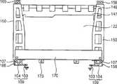
图1是示出根据本发明实施例的显示装置的前面的平面图;1 is a plan view showing the front of a display device according to an embodiment of the present invention;
图2是示出图1中的显示装置的后面的平面图;FIG. 2 is a plan view showing the rear of the display device in FIG. 1;
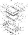
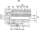
图3是示出图1中的显示装置的分解透视图;FIG. 3 is an exploded perspective view showing the display device in FIG. 1;
图4是示出沿图3中的线II-II′截取的显示装置的剖视图;4 is a cross-sectional view showing the display device taken along line II-II' in FIG. 3;
图5是示出沿图3中的线I-I′截取的显示装置的剖视图;5 is a cross-sectional view showing the display device taken along line II' in FIG. 3;
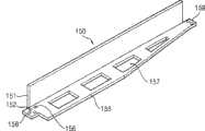
图6是示出图3中的第一侧支架的透视图;FIG. 6 is a perspective view showing the first side bracket in FIG. 3;
图7是示出图3中的固定框架的透视图;FIG. 7 is a perspective view showing the fixed frame in FIG. 3;
图8是示出图1中的连接到第二侧支架的固定框架的透视图;8 is a perspective view showing a fixed frame connected to a second side bracket in FIG. 1;
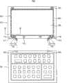
图9是示出具有图1中的显示装置的信息处理装置的平面图;9 is a plan view showing an information processing device having the display device in FIG. 1;
图10是示出沿图9中的线III-III′截取的信息处理装置的剖视图;10 is a sectional view showing the information processing device taken along line III-III' in FIG. 9;
图11是示出根据本发明另一实施例的显示装置的剖视图。FIG. 11 is a cross-sectional view illustrating a display device according to another embodiment of the present invention.
具体实施方式Detailed ways
在下文中,将参照附图更充分地描述本发明,在附图中示出了本发明的实施例。然而,本发明可以以多种不同的形式来实施,不应该被理解为局限于在此提出的示例实施例。相反,提供这些示例实施例使本公开将是彻底的和完全的,并将本发明的范围充分地传达给本领域的技术人员。在附图中,为了清晰起见,会夸大层和区域的尺寸和相对尺寸。Hereinafter, the invention will be described more fully with reference to the accompanying drawings, in which embodiments of the invention are shown. This invention may, however, be embodied in many different forms and should not be construed as limited to the example embodiments set forth herein. Rather, these example embodiments are provided so that this disclosure will be thorough and complete, and will fully convey the scope of the invention to those skilled in the art. In the drawings, the size and relative sizes of layers and regions may be exaggerated for clarity.
应该理解,当元件或层被称作“在”另一元件或另一层“上”、“连接到”另一元件或另一层或者“结合到”另一元件或另一层时,该元件或层可以在另一元件或另一层上、连接到另一元件或另一层或者结合到另一元件或另一层,并存在中间元件或中间层。相反,当元件被称作“直接在”另一元件或另一层“上”、“直接连接到”另一元件或另一层或者“直接结合到”另一元件或另一层时,不存在中间元件或中间层。相同的标号始终表示相同的元件。如这里所使用的,术语“和/或”包括一个或多个相关所列的项目的任意组合和所有组合。It will be understood that when an element or layer is referred to as being "on," "connected to," or "bonded to" another element or layer, that An element or layer can be on, connected to, or bonded to another element or layer, with intervening elements or layers present. In contrast, when an element is referred to as being "directly on," "directly connected to," or "directly coupled to" another element or layer, it does not mean that There are intermediate elements or layers. Like reference numerals refer to like elements throughout. As used herein, the term "and/or" includes any and all combinations of one or more of the associated listed items.
应该理解的是,尽管在这里可使用术语第一、第二等来描述不同的元件、组件、区域、层和/或部分,但是这些元件、组件、区域、层和/或部分并不应受这些术语的限制。这些术语仅是用来将一个元件、组件、区域、层或部分与另一个元件、组件、区域、层或部分区分开来。因此,在不脱离本发明的教导的情况下,下面讨论的第一元件、组件、区域、层或部分可被命名为第二元件、组件、区域、层或部分。It should be understood that although the terms first, second, etc. may be used herein to describe various elements, components, regions, layers and/or sections, these elements, components, regions, layers and/or sections should not be constrained by limitations of these terms. These terms are only used to distinguish one element, component, region, layer or section from another element, component, region, layer or section. Thus, a first element, component, region, layer or section discussed below could be termed a second element, component, region, layer or section without departing from the teachings of the present invention.
为了方便描述,在这里可使用如“在...之下”、“在...下方”、“下面的”、“在...上方”、“上面的”等的空间相对术语来描述如图中所示的一个元件或特征与其它元件或特征的关系。应该理解的是,空间相对术语意在包含除了在附图中描述的方位之外的装置在使用或操作中的不同方位。例如,如果在附图中装置被翻转,则描述为“在”其它元件或特征“之下”或“下方”的元件随后将被定位为“在”其它元件或特征“上方”。因此,示例性术语“在...下方”可包括“在...上方”和“在...下方”两种方位。所述装置可被另外定位(例如旋转90度或者在其它方位),并相应地解释这里使用的空间相对描述符。For the convenience of description, spatial relative terms such as "under", "below", "below", "above", "above" etc. may be used here to describe The relationship of one element or feature to other elements or features as shown in the figures. It will be understood that the spatially relative terms are intended to encompass different orientations of the device in use or operation in addition to the orientation depicted in the figures. For example, if the device in the figures is turned over, elements described as "below" or "beneath" other elements or features would then be oriented "above" the other elements or features. Thus, the exemplary term "below" can encompass both an orientation of "above" and "beneath". The device may be otherwise positioned (eg, rotated 90 degrees or at other orientations) and the spatially relative descriptors used herein interpreted accordingly.
这里使用的术语仅为了描述特定实施例的目的,而不意图限制本发明。如这里所使用的,除非上下文另外明确指出,否则单数形式也意图包括复数形式。还将理解的是,当在本说明书中使用术语“包含”和/或“包括”时,说明存在所述特征、整体、步骤、操作、元件和/或组件,但不排除存在或附加一个或多个其它特征、整体、步骤、操作、元件、组件和/或其组合。The terminology used herein is for the purpose of describing particular embodiments only and is not intended to be limiting of the invention. As used herein, singular forms are intended to include plural forms unless the context clearly dictates otherwise. It will also be understood that when the terms "comprising" and/or "comprising" are used in this specification, it means that the features, integers, steps, operations, elements and/or components exist, but does not exclude the existence or addition of one or more Various other features, integers, steps, operations, elements, components and/or combinations thereof.
在此参照作为本发明的理想实施例(和中间结构)的示意性示出的剖视图来描述本发明的示例实施例。这样,预计会出现例如由制造技术和/或公差引起的示出的形状变化。因此,本发明的示例实施例不应该被解释为限制于在此示出的区域的具体形状,而应该包括例如由制造导致的形状变形。例如,示出为矩形的注入区域在其边缘通常具有倒圆或曲线的特征和/或注入浓度的梯度,而不是从注入区域到非注入区域的二元变化。同样地,通过注入形成的掩埋区域可导致在掩埋区域和通过其发生注入的表面之间的区域中出现一定程度的注入。因此,在图中示出的区域实际上是示意性的,它们的形状并不意图示出装置的区域的实际形状,也不意图限制本发明的范围。Example embodiments of the invention are described herein with reference to cross-section illustrations that are schematic illustrations of idealized embodiments (and intermediate structures) of the invention. As such, variations in the shapes shown that result, for example, from manufacturing techniques and/or tolerances, are to be expected. Thus, example embodiments of the present invention should not be construed as limited to the particular shapes of regions illustrated herein but are to include deviations in shapes that result, for example, from manufacturing. For example, an implanted region illustrated as a rectangle will, typically, have rounded or curved features and/or a gradient of implant concentration at its edges rather than a binary change from implanted to non-implanted region. Likewise, a buried region formed by implantation may result in a certain degree of implantation in the region between the buried region and the surface through which the implantation takes place. Thus, the regions illustrated in the figures are schematic in nature and their shapes are not intended to illustrate the actual shape of a region of a device and are not intended to limit the scope of the invention.
除非另有定义,否则这里使用的所有术语(包括技术术语和科学术语)具有与本发明所属领域的普通技术人员所通常理解的意思相同的意思。将进一步理解,除非这里明确定义,否则术语例如在通用的字典中定义的术语应该被解释为具有与相关领域的上下文中它们的意思相一致的意思,而不是理想地或者过于正式地解释它们的意思。Unless otherwise defined, all terms (including technical and scientific terms) used herein have the same meaning as commonly understood by one of ordinary skill in the art to which this invention belongs. It will be further understood that unless expressly defined herein, terms such as those defined in commonly used dictionaries should be construed to have meanings consistent with their meanings in the context of the relevant art, rather than interpreting them ideally or overly formally. mean.
图1是示出根据本发明实施例的显示装置的前面的平面图。图2是示出了图1中的显示装置的后面的平面图。图3是示出了图1中的显示装置的分解透视图。FIG. 1 is a plan view showing the front of a display device according to an embodiment of the present invention. FIG. 2 is a plan view showing the rear of the display device in FIG. 1 . FIG. 3 is an exploded perspective view showing the display device in FIG. 1 .
参照图1至图3,显示装置100包括显示模块101、支撑框架和固定框架170。Referring to FIGS. 1 to 3 , the
显示模块101可包括背光单元102和显示面板单元105。背光单元102发射光。显示面板单元105利用发射的光来显示图像。图1中示出了显示面板单元105的前面。图2中示出了背光单元102的后面。下面描述背光单元102和显示面板单元105。The
支撑框架支撑显示模块101的多个侧面。支撑框架可包括第一侧支架150和第二侧支架160。The support frame supports sides of the
第一侧支架150可面向第二侧支架160。第一侧支架150和第二侧支架160可分别支撑背光单元102的彼此相对的侧面以及显示面板单元105的彼此相对的侧面。第一侧支架150和第二侧支架160中的每个可分别为利用金属形成的机壳。可选择地,第一侧支架150和第二侧支架160可为利用塑料通过注塑方法形成的模制框架。The
结合部分形成在支撑框架上。结合部分可用于将显示模块101机械地连接到与显示模块101分开的信息输入装置。例如,结合部分可用于将显示模块101与笔记本计算机的包括键盘的主体铰接。The coupling portion is formed on the support frame. The coupling portion may be used to mechanically connect the
结合部分可沿纵向方向形成在第一侧支架150和第二侧支架160的端部上。第一结合孔可形成在结合部分上。A coupling portion may be formed on end portions of the
固定框架170可为包含金属的机壳。可选择地,固定框架170可为利用塑料通过注塑方法形成的模制框架。The fixing
固定框架170可被固定到背光单元102的后面和支撑框架。在该实施例中,固定框架170被分别固定到第一侧支架150和第二侧支架160。因此,通过固定框架170可提高第一侧支架150和第二侧支架160之间的距离的均匀性。The fixing
固定框架170与第一侧支架150和第二侧支架160一起容纳显示模块101。显示模块101被固定框架170、第一侧支架150和第二侧支架160支撑,并被固定到固定框架170、第一侧支架150和第二侧支架160。The fixing
下面详细地描述第一侧支架150、第二侧支架160和固定框架170。The
图4是示出了沿图3中的线II-II′截取的显示装置的剖视图。FIG. 4 is a cross-sectional view illustrating the display device taken along line II-II' in FIG. 3 .
参照图3和图4,背光单元102可包括容纳框架110、导光板121和光源127。Referring to FIGS. 3 and 4 , the
容纳框架110可利用塑料材料形成。容纳框架110可具有方形形状。例如,容纳框架110可包括第一侧壁111、第二侧壁113、第三侧壁115、第四侧壁117和底部119。The receiving
第一侧壁111面向第二侧壁113。第三侧壁115面向第四侧壁117。第三侧壁115和第四侧壁117沿基本垂直于第一侧壁111或第二侧壁113的纵向方向的方向设置。底部119从第一侧壁111、第二侧壁113、第三侧壁115和第四侧壁117延伸。开口形成在底部119的中部。可选择地,第一侧壁111、第二侧壁113、第三侧壁115和第四侧壁117中的至少一个可被省略。The
导光板121容纳在容纳框架110中。导光板121包括多个侧面、发光面和反光面。侧面分别面向第一侧壁111、第二侧壁113、第三侧壁115和第四侧壁117。发光面与反光面相对。反光面面向底部119。发光面和反光面通过侧面相互连接。The
导光板121可利用漫射光的材料形成,其中,所述漫射光的材料具有如透光性、耐热、耐化学性和机械强度等各种特性。可用作该漫射光的材料的漫射光的材料的示例包括聚乙烯、聚甲基丙烯酸甲酯、聚酰胺、聚酰亚胺、聚丙烯、聚氨酯等。The
背光单元102还可包括反射片122和光学片125。The
反射片122设置在容纳框架110的底部119和导光板121的反光面之间,以覆盖底部119的开口。反射片122将从反光面泄露的光向导光板121反射。The
光学片125设置在导光板121的发光面上。光学片125改善从发光面发射的光的光学特性。例如,光学片125可以包括设置在发光面上的漫射片和设置在漫射片上的多个会聚片。漫射片漫射从发光面发射的光,以改善光的亮度均匀性。会聚片可以为棱镜片。会聚片可以设置在漫射片上。例如,会聚片的会聚方向可以基本彼此垂直。The
光源127设置在第一侧壁111和导光板121的面向第一侧壁111的侧面之间。可选择地,光源127可以面向导光板121的其它的侧面。光源127可以为冷阴极荧光灯(CCFL)。可选择地,光源127可以为发光二极管(LED)。The
背光单元102还可以包括灯反射器126。灯反射器126围绕光源127,并将从光源127发射的光向导光板121的侧面反射。The
可以使入射到导光板121中的光从侧面、发光面和反光面反复反射,从而从发光面发射光。诸如点图案的光学图案可以形成在反光面上,使得所述光学图案可以反射并漫射光。因此,从光源127发射的光被转换为面光,并从发光面发射所述面光。The light incident into the
显示面板单元105设置在光学片125上。显示面板单元105基于通过光学片125控制了光学特性的光来显示图像。显示面板单元105可以包括显示面板140、驱动板147和柔性连接膜149。The
显示面板140可以包括下基板141、上基板145和液晶层(未示出)。The
例如,下基板141可以包括下透明基板、数据信号线(未示出)、第一栅极驱动部件和第二栅极驱动部件。For example, the
如图1中所示,下透明基板上的显示区域10与显示屏幕对应。下透明基板上的第一外围区域11与第一侧壁111对应。下透明基板上的第二外围区域13与第二侧壁113对应。下透明基板上的第三外围区域15与第三侧壁115对应。下透明基板上的第四外围区域17与第四侧壁117对应。第一外围区域11、第二外围区域13、第三外围区域15和第四外围区域17围绕显示区域。As shown in FIG. 1, the display area 10 on the lower transparent substrate corresponds to the display screen. The first peripheral region 11 on the lower transparent substrate corresponds to the
多个像素、数据线和栅极线形成在显示区域中。像素包括开关装置和电连接到开关装置的漏电极的像素电极。A plurality of pixels, data lines and gate lines are formed in the display area. A pixel includes a switching device and a pixel electrode electrically connected to a drain electrode of the switching device.
栅极线电连接到开关装置的栅电极。数据线与栅极线交叉,并电连接到开关装置的源电极。The gate line is electrically connected to the gate electrode of the switching device. The data lines cross the gate lines and are electrically connected to source electrodes of the switching devices.
通过源电极将施加到数据线的数据信号施加到像素电极。通过栅极线将控制信号施加到栅电极,从而控制信号可以控制将数据信号向像素电极的施加。The data signal applied to the data line is applied to the pixel electrode through the source electrode. The control signal is applied to the gate electrode through the gate line, so that the control signal can control the application of the data signal to the pixel electrode.
数据信号线形成在第二外围区域上,以电连接到数据线。Data signal lines are formed on the second peripheral region to be electrically connected to the data lines.
第一栅极驱动部件形成在第三外围区域上。第一栅极驱动部件驱动第一组栅极线,例如,奇数栅极线。第二栅极驱动部件形成在第四外围区域上。第二栅极驱动部件驱动第二组栅极线,例如,偶数栅极线。The first gate driving part is formed on the third peripheral region. The first gate driving part drives a first group of gate lines, for example, odd-numbered gate lines. The second gate driving part is formed on the fourth peripheral region. The second gate driving part drives a second group of gate lines, for example, even-numbered gate lines.
上基板145面向下基板141。上基板145可以包括上透明基板、滤色器和共电极。滤色器设置在上透明基板上,使得滤色器分别与像素对应。滤色器可以包括红色滤色器、绿色滤色器和蓝色滤色器。共电极可以形成在覆盖滤色器的整个平坦化层的上方。The
液晶层设置在下基板141和上基板145之间。The liquid crystal layer is disposed between the
显示面板140还可以包括下偏振板和上偏振板。下偏振板设置在下基板141的下面上。上偏振板设置在上基板145的上面上。The
驱动板147可以通过第二外围区域电连接到数据信号线、第一栅极驱动部件和第二栅极驱动部件。The driving
从显示区域10的中心到第三外围区域15的端部的第一距离可以与从显示区域10的中心到第四外围区域17的端部的第二距离基本相同。The first distance from the center of the display area 10 to the end of the third peripheral area 15 may be substantially the same as the second distance from the center of the display area 10 to the end of the fourth peripheral area 17 .
柔性连接膜149将驱动板147与数据信号线、第一栅极驱动部件和第二栅极驱动部件电连接。The
通过柔性连接膜149,驱动板147可以将诸如数据信号的面板驱动信号输出到数据信号线,并且也可以将栅极信号输出到第一栅极驱动部件和第二栅极驱动部件。驱动板147可以控制像素电极和共电极之间的电场强度,从而像素电极和共电极之间的液晶的布置可以变化以改变液晶层的透光性。Through the
通过下偏振板使从光学片125发射的光偏振。偏振光入射到液晶层中。通过液晶层的透光性来确定透射液晶层的光的量。通过上偏振板使已经穿过液晶层的光偏振,从而通过已经穿过上偏振板的光来显示图像。Light emitted from the
可以通过容纳框架110的第一侧壁111来支撑显示面板140的第四侧面,例如,下基板141的第一侧面,可以通过第二侧壁113的上端部来支撑显示面板140,如图4中所示。可选择地,可以通过第一侧壁111的上端部来支撑显示面板140,并可以通过容纳框架110的第二侧壁113来支撑下基板141的第三侧面。The fourth side of the
图5是示出沿图3中的线I-I′截取的显示装置的剖视图。图6是示出图3中第一侧支架150的透视图。FIG. 5 is a cross-sectional view illustrating the display device taken along line II' in FIG. 3 . FIG. 6 is a perspective view illustrating the
参照图3、图5和图6,可以通过第三侧壁115和第四侧壁117的上部来支撑显示面板140。Referring to FIGS. 3 , 5 and 6 , the
第一侧支架150可以支撑第三侧壁115、显示面板140的第一侧面和连接到第三侧壁115的底部119。第一侧支架150可以包括第一侧板151和第一底板155。The
第一侧板151面向第三侧壁115,并且具有的高度大于第三侧壁115的高度。因此,第一侧板151可以支撑第三侧壁115和显示面板140的第一侧面。第一底板155从第一侧板151延伸,以面向底部119。沿与第一侧支架150的纵向方向垂直的平面截取的第一侧支架150的剖视图可以具有L形状。The
开口157形成为穿过第一底板155,以降低第一侧支架150的重量。第一连接孔156形成在第一底板155的沿纵向方向的端部上,从而第一连接孔156被用于将第一侧支架150连接到固定框架170。An
第一结合部分可以指形成在第一底板155上的结合部分。例如,第一结合部分158和159可以分别从第一底板155的端部沿纵向方向延伸,如图1和图6中所示。第一结合孔152分别形成在第一结合部分158和159上。The first bonding part may refer to a bonding part formed on the
第二侧支架160可以具有关于第一侧支架150基本对称的形状。第二侧支架160可以支撑第四侧壁117、显示面板140的第二侧面和连接到第四侧壁117的底部119。第二侧支架160可以包括第二侧板161和第二底板165。The
第二侧板161面向第四侧壁117,并可以支撑第四侧壁117和显示面板140的第二侧面。第二底板165从第二侧板161延伸,以面向底部119。The
第二结合部分可以指形成在第二底板165上的结合部分。例如,第二结合部分168和169可以分别从第二底板165的端部沿纵向方向延伸,如图1中所示。第一结合孔162分别形成在第二结合部分168和169上。The second bonding part may refer to a bonding part formed on the
可选择地,支撑框架还可以包括第三侧支架。第三侧支架可以设置在第二侧壁113上。第三侧支架可以包括第三侧板和第三底板。第三侧板可以支撑第二侧壁113和显示面板140的第三侧面。第三底板可以支撑连接到第二侧壁113的底部119。Optionally, the support frame may further include a third side bracket. A third side bracket may be disposed on the
显示装置100还可以包括保护构件180。The
第一个保护构件180设置在第一侧板151和第三侧壁115之间,第二个保护构件180设置在第二侧板161和第四侧壁117之间。保护构件180分别向上延伸到第一侧板151和第二侧板161的上端部,使得保护构件180可以引导显示面板140的第一侧面和第二侧面。保护构件180可以包括衬垫、所述衬垫可以使用用于振动缓冲的橡胶形成。The
使用玻璃形成的显示面板140的第一侧面和第二侧面可以与使用金属形成的第一侧板151和第二侧板161分开,使得显示面板140的第一侧面和第二侧面接触相对于玻璃具有良好接触特性的保护构件180。因此,保护显示面板140不受由外部冲击导致的损坏,并可以防止显示面板140和保护构件180分开。The first and second sides of the
图7是示出图3中的固定框架的透视图。图8是示出连接到第二侧支架160的固定框架的透视图。FIG. 7 is a perspective view illustrating a fixing frame in FIG. 3 . FIG. 8 is a perspective view illustrating a fixing frame connected to the
参照图3、图4、图5和图7,固定框架170连接到第一侧支架150和第二侧支架160,以面向与第一侧壁111相邻的底部119。固定框架170保护光源127不受外部冲击。固定框架170可以延伸以面向第一侧壁111。可选择地,固定框架170可以仅设置在底部119上。Referring to FIGS. 3 , 4 , 5 and 7 , the fixing
参照图2和图8,固定框架170的沿纵向方向的端部设置在第一侧支架150的第一底板155和第二侧支架160的第二底板165上。第二连接孔171形成在固定框架170的端部上,从而使用螺钉来装配第一底板155和第二底板165的第一连接孔156与第二连接孔171。连接部分173从固定框架170沿宽度方向的边缘突出,螺钉连接孔175形成在连接部分173上。连接部分173用于将显示装置100与容纳显示装置100的壳体连接。Referring to FIGS. 2 and 8 , ends of the fixing
如图5和图8中所示,可以为连接螺钉的第一连接构件177通过固定框架170的第二连接孔171和第一底板155的第一连接孔156插入到容纳框架110的底部119中。另一连接螺钉通过固定框架170的第二连接孔171和第二底板165的第一连接孔156插入到容纳框架110的底部119中。因此,孔或凹陷可以形成在底部119上以用于螺钉连接。As shown in FIGS. 5 and 8 , the first connecting
通过连接固定框架170、第一底板155和第二底板165,第一侧支架150和第二侧支架160之间的距离的均匀性提高,从而固定框架170、第一侧支架150和第二侧支架160可以一起形成容器。By connecting the fixed
参照图8,显示装置100还可以包括组合构件109。组合构件109中的每个可以连接到第一结合部分158和第二结合部分168中的每个。Referring to FIG. 8 , the
组合构件109可以为铰链连接构件。组合构件109可以包括组合部分104和铰链部分103。第二结合孔107形成在组合部分104上,并与第二结合部分168的第一结合孔162对应。组合部分104设置在第二结合部分168上,从而第二结合孔107布置在第一结合孔162上。铰链部分103连接到组合部分104,使得铰链部分103可以绕组合部分104旋转。The
显示装置100可以包括第二连接构件178。通过第一结合孔152和162以及第二结合孔107,第二连接构件178(例如,螺钉)将第一结合部分158与第一个组合构件109连接,并将第二结合部分168与第二个组合构件109连接。当壳体容纳显示装置100时,螺钉可以插入到壳体的后面中。The
组合构件109的铰链部分103可以连接到信息输入装置。因此,显示装置100可以绕信息输入装置旋转。例如,显示装置100可以为笔记本计算机的监视器,信息输入装置可以为笔记本计算机的包括键盘的主体。The
再次参照图3、图4和图5,显示装置100还可以包括固定构件。固定构件190将显示面板140固定到第一侧支架150和第二侧支架160。固定构件可以包括粘结带190。Referring again to FIGS. 3 , 4 and 5 , the
粘结带190可以分别设置在显示面板140的四个边缘上,如图3中所示。每个粘结带190可以粘结到上基板145的边缘,例如,与第一外围区域11、第二外围区域13、第三外围区域15和第四外围区域17对应的区域。
每个粘结带190沿第一侧支架150的第一侧板151、第二侧支架160的第二侧板161以及容纳框架110的第一侧壁111和第二侧壁113弯曲,从而粘结带190分别粘结到第一侧支架150的第一底板155、第二侧支架160的第二底板165和容纳框架110的底部119。因此,显示面板单元105通过粘结带190牢固地固定到容纳框架110、第一侧支架150和第二侧支架160。Each
设置在第二侧壁113上的粘结带190可以覆盖驱动板147以保护驱动板147,驱动板147设置在与第二侧壁113相邻的底部上。例如,仅粘结带190的与第一外围区域11、第二外围区域13、第三外围区域15、第四外围区域17、第一底板155、第二底板165和底部119对应的一部分可以为粘性的,并且粘结带190的剩余部分可以为非粘性的。The
在另一实施例中,传统显示装置中的底部机壳和后盖可以形成基本容纳并保护显示面板单元和背光单元的容器。根据与本实施例一致的显示装置100,固定框架170和包括第一侧支架150和第二侧支架160的支撑框架装配到基本容纳并保护显示面板单元105和背光单元102的容器中。In another embodiment, the bottom chassis and the rear cover in the conventional display device may form a container that substantially accommodates and protects the display panel unit and the backlight unit. According to the
在另一实施例中,顶部机壳将显示面板固定到底部机壳。根据与本实施例一致的显示装置100,诸如粘结带190的固定构件190将显示面板140固定到支撑框架和固定框架170。In another embodiment, the top chassis secures the display panel to the bottom chassis. According to the
因此,根据与本实施例一致的显示装置100,可以省略底部机壳、后盖和顶部机壳,从而降低显示装置100的厚度和重量。Therefore, according to the
在另一实施例中,通过与传统的显示装置分开的支架构件,显示装置可以连接并固定到壳体构件。根据与本实施例一致的显示装置100,显示装置100通过显示装置100的第一侧支架150和第二侧支架160连接并固定到壳体。In another embodiment, the display device may be connected and fixed to the case member through a bracket member separate from the conventional display device. According to the
第一侧支架150和第二侧支架160分别包括机械连接到信息输入装置的第一结合部分158和第二结合部分168。组合构件109将显示装置100的第一结合部分158和第二结合部分168连接到信息输入装置。因此,在显示装置100连接到信息输入装置的同时,显示装置100可以绕信息输入装置旋转。The
图9是示出具有图1中的显示装置的信息处理装置的平面图。图10是示出沿图9中的线III-III′截取的信息处理装置的剖视图。FIG. 9 is a plan view showing an information processing device having the display device in FIG. 1 . FIG. 10 is a cross-sectional view showing the information processing device taken along line III-III' in FIG. 9 .
参照图9和图10,信息处理装置700包括显示装置701、后壳体810和前壳体850。Referring to FIGS. 9 and 10 , the
显示装置701可以与图1至图8中示出的显示装置100基本相同,因此,显示装置701可以包括背光单元、显示面板单元705、第一侧支架750、第二侧支架760和固定框架770。The
背光单元可以包括容纳框架710、导光板721和光源。The backlight unit may include a receiving
容纳框架710可以包括彼此面对的第一侧壁和第二侧壁、将第一侧壁连接到第二侧壁并且也彼此面对的第三侧壁和第四侧壁以及从第一侧壁、第二侧壁、第三侧壁和第四侧壁延伸的底部719。The receiving
导光板721容纳在容纳框架710中。The
光源设置在第一侧壁和导光板721的侧面之间。The light source is disposed between the first side wall and the side of the
显示面板单元705设置在背光单元上,并基于从背光单元发射的光来显示图像。显示面板单元705可以包括下基板741、上基板745和液晶层。The
下基板741上的显示区域与显示屏幕对应。下基板741上的第一外围区域与第一侧壁对应。下基板741上的第二外围区域与第二侧壁对应。下基板741上的第三外围区域与第三侧壁对应。下基板741上的第四外围区域与第四侧壁对应。第一外围区域、第二外围区域、第三外围区域和第四外围区域围绕显示区域。A display area on the
前壳体850容纳显示装置701以暴露显示屏幕。前壳体850包括分别与第一外围区域、第二外围区域、第三外围区域和第四外围区域对应的上边框、下边框、左边框和右边框。The
在与本实施例一致的信息处理装置700中,显示区域的中心和第三外围区域的边缘之间的第一距离与显示区域的中心和第四外围区域的边缘之间的第二距离基本相同。因此,显示面板740的中心可以与显示区域的中心基本相同。当左边框的宽度与右边框的宽度基本相同时,在显示面板740的侧面和从前壳体850的左边框和右边框延伸的侧面之间不会形成缝隙。In the
第一侧支架750支撑第三侧壁、与第三侧壁相邻的底部719和显示面板740的第一侧面。第一结合部分可以从第一侧支架750的端部沿纵向方向延伸。The first side frame 750 supports the third side wall, the bottom 719 adjacent to the third side wall, and the first side of the
第二侧支架760支撑第四侧壁、与第四侧壁相邻的底部719和显示面板740的第二侧面。第二结合部分可以从第二侧支架760的端部沿纵向方向延伸。The second side frame 760 supports the fourth side wall, the bottom 719 adjacent to the fourth side wall, and the second side of the
固定框架770设置在与第一侧壁相邻的底部719上。固定框架770连接到第一侧支架750、第二侧支架760和底部719,从而固定框架770将容纳框架710固定到第一侧支架750和第二侧支架760。A fixing
后壳体810面向前壳体850,以容纳背光单元。后壳体810包括第三结合部分和第四结合部分。第三结合部分连接到第一结合部分,第四结合部分连接到第二结合部分。The
前壳体850连接到后壳体810以暴露显示屏幕。The
信息处理装置700还可以包括信息输入装置801和铰链连接构件709。信息输入装置801和铰链连接构件709可以与图1至图8中示出的信息输入装置和铰链连接构件109基本相同。The
例如,背光单元和显示面板单元705可以装配成笔记本计算机的监视器,信息输入装置801可以为笔记本计算机的包括键盘的主体。For example, the backlight unit and the
信息输入装置801接收可以显示在显示面板单元705的显示屏幕上的信息。信息输入装置801可以包括第五结合部分803和第六结合部分805。The
铰链连接构件709将第一结合部分连接到第五结合部分803,并将第二结合部分连接到第六结合部分805。因此,在显示装置701可以连接到信息输入装置801的同时,显示装置701可以绕信息输入装置801旋转。The
信息处理装置700还可以包括粘结构件790。粘结构件790粘结到显示装置701的与第一外围区域、第二外围区域、第三外围区域以及第四外围区域对应的区域。粘结构件790沿第一侧支架750、第二侧支架760以及容纳框架710的第一侧壁和第二侧壁弯曲,从而粘结构件790粘结到容纳框架710的底部719。The
信息处理装置700还可以包括信号传输电线830。信号传输电线830可以设置在后壳体810和第一侧支架750的第一底板755之间。可选择地,信号传输电线830可以设置在后壳体810和第二侧支架760的第二底板之间。The
信号传输电线830可以为信号接收天线。信号传输电线830可以将从外部接收的信号传输到信息输入装置801或显示面板单元705。引导信号传输电线830的引导凹陷815可以形成在后壳体810上。The signal transmission wire 830 may be a signal receiving antenna. The signal transmission wire 830 may transmit a signal received from the outside to the
图11是示出根据另一实施例的显示装置的剖视图。FIG. 11 is a cross-sectional view showing a display device according to another embodiment.
参照图11,除了支撑框架和固定框架370之间的连接之外,显示装置300与图1至图8中示出的显示装置100基本相同。Referring to FIG. 11 , the display device 300 is substantially the same as the
在本实施例中,可以为连接突起354的第一相连部分354形成在第一底板和第二底板的面向容纳框架310的底部319的上面上。连接到第一相连部分354的可以为连接凹槽的第二相连部分形成在底部319上。In this embodiment, a first connection portion 354 , which may be a connection protrusion 354 , is formed on upper surfaces of the first and second bottom plates facing the bottom 319 of the receiving frame 310 . A second connection portion, which may be a connection groove, connected to the first connection portion 354 is formed on the bottom 319 .
可以为连接突起356的第三相连部分356还形成在第一底板和第二底板的下面上,可以为连接凹陷的连接到第三相连部分356的第四相连部分形成在固定框架370上。A third connection portion 356 , which may be a connection protrusion 356 , is also formed on the undersides of the first and second bottom plates, and a fourth connection portion, which may be a connection recess, connected to the third connection portion 356 is formed on the fixing frame 370 .
根据与本实施例一致的显示装置300,用于连接的螺钉的数量可以减少,从而可以减少显示装置300中使用的元件的数量,并可以简化装配工艺。According to the display device 300 consistent with the present embodiment, the number of screws used for connection can be reduced, so that the number of components used in the display device 300 can be reduced and the assembly process can be simplified.
除了本实施例的信息处理装置包括根据本实施例的显示装置300之外,根据本实施例的信息处理装置与图9和图10中示出的信息处理装置700基本相同。The information processing device according to the present embodiment is basically the same as the
另一实施例的显示装置通过与传统的显示装置分开的支架构件连接并固定到壳体构件。根据图1至图10中的信息处理装置,显示装置通过显示装置的第一侧支架和第二侧支架连接并固定到前壳体和后壳体。A display device of another embodiment is connected and fixed to a case member through a stand member separate from a conventional display device. According to the information processing device in FIGS. 1 to 10 , the display device is connected and fixed to the front case and the rear case through the first side bracket and the second side bracket of the display device.
第一侧支架和第二侧支架分别包括机械连接到信息输入装置的第一结合部分和第二结合部分。组合构件将显示装置的第一结合部分和第二结合部分连接到信息输入装置。因此,在结合部分连接到信息输入装置的情况下,显示装置可以绕信息输入装置旋转。The first side bracket and the second side bracket include first and second coupling portions mechanically connected to the information input device, respectively. The combination member connects the first coupling part and the second coupling part of the display device to the information input device. Therefore, the display device can be rotated around the information input device with the coupling portion connected to the information input device.
因此,根据与本实施例一致的显示装置和信息处理装置,不需要传统的底部机壳和传统的后盖,且不需要额外的侧支架构件。此外,可以省略传统的顶部机壳。Therefore, according to the display device and the information processing device consistent with the present embodiment, a conventional bottom cabinet and a conventional rear cover are not required, and an additional side frame member is not required. Furthermore, the traditional top case can be omitted.
因此,根据本实施例的显示装置和信息处理装置可以用于简化显示装置(诸如笔记本计算机或壁挂电视接收机组)和信息处理装置的框架结构。Therefore, the display device and the information processing device according to the present embodiment can be used to simplify the frame structure of the display device (such as a notebook computer or a wall-mounted television receiver set) and the information processing device.
前述示出了本发明,且不被解释为对本发明的限制。虽然已经描述了本发明的示例实施例,但是本领域技术人员应该容易理解,在不实质脱离本发明的新颖性的教导和优点的情况下,可以对示例实施例进行许多修改。因此,所有这些修改意在包括在本发明的限定在权利要求中的范围内。应该理解的是,前述是示出本发明,且不被解释为局限于公开的实施例,并且对于公开的实施例以及其它实施例的修改意在被包括在权利要求的范围内。本发明由权利要求及其等同物限定。The foregoing illustrates the invention and is not to be construed as limiting the invention. Although an example embodiment of this invention has been described, those skilled in the art will readily appreciate that many modifications are possible in the example embodiment without materially departing from the novel teachings and advantages of this invention. Accordingly, all such modifications are intended to be included within the scope of this invention as defined in the claims. It is to be understood that the foregoing is illustrative of the invention and is not to be construed as limited to the disclosed embodiments and that modifications to the disclosed embodiments as well as other embodiments are intended to be included within the scope of the claims. The invention is defined by the claims and their equivalents.
Claims (27)
Applications Claiming Priority (3)
| Application Number | Priority Date | Filing Date | Title |
|---|---|---|---|
| KR10-2007-0113457 | 2007-11-08 | ||
| KR1020070113457AKR101386927B1 (en) | 2007-11-08 | 2007-11-08 | Display device and information processing device having the same |
| KR1020070113457 | 2007-11-08 |
Publications (2)
| Publication Number | Publication Date |
|---|---|
| CN101430845Atrue CN101430845A (en) | 2009-05-13 |
| CN101430845B CN101430845B (en) | 2012-10-24 |
Family
ID=40193486
Family Applications (1)
| Application Number | Title | Priority Date | Filing Date |
|---|---|---|---|
| CN2008101741250AExpired - Fee RelatedCN101430845B (en) | 2007-11-08 | 2008-11-07 | Display device and information processing device having the same |
Country Status (4)
| Country | Link |
|---|---|
| US (1) | US8040455B2 (en) |
| EP (1) | EP2058693B1 (en) |
| KR (1) | KR101386927B1 (en) |
| CN (1) | CN101430845B (en) |
Cited By (11)
| Publication number | Priority date | Publication date | Assignee | Title |
|---|---|---|---|---|
| CN102237063A (en)* | 2010-04-27 | 2011-11-09 | 乐金显示有限公司 | Display apparatus |
| CN102652277A (en)* | 2010-10-28 | 2012-08-29 | Lg电子株式会社 | display screen |
| CN103561549A (en)* | 2012-04-04 | 2014-02-05 | 仁宝电脑工业股份有限公司 | Display device and manufacturing method thereof |
| CN103955083A (en)* | 2014-01-17 | 2014-07-30 | 友达光电股份有限公司 | Display module support and display module using same |
| CN107357063A (en)* | 2016-05-09 | 2017-11-17 | 三星显示有限公司 | Display device and the tiled display equipment for including the display device |
| CN107396552A (en)* | 2016-05-03 | 2017-11-24 | B·布莱恩·阿维图姆股份公司 | Device for integrating a screen or display in a housing |
| CN107708369A (en)* | 2010-11-11 | 2018-02-16 | 苹果公司 | Around the insert-molded of the glass component of portable electric appts |
| CN109404865A (en)* | 2018-11-16 | 2019-03-01 | 西安交通大学 | Modular multi-function quartz lamp carry frame |
| WO2021000445A1 (en)* | 2019-07-02 | 2021-01-07 | 武汉华星光电半导体显示技术有限公司 | Display device |
| US11187848B2 (en)* | 2018-05-31 | 2021-11-30 | Panasonic Intellectual Property Management Co., Ltd. | Image display device |
| CN116794882A (en)* | 2023-06-30 | 2023-09-22 | 高创(苏州)电子有限公司 | Backlight modules, LCD modules and electronic equipment |
Families Citing this family (31)
| Publication number | Priority date | Publication date | Assignee | Title |
|---|---|---|---|---|
| KR101386927B1 (en)* | 2007-11-08 | 2014-04-18 | 삼성디스플레이 주식회사 | Display device and information processing device having the same |
| TWI383201B (en)* | 2008-02-26 | 2013-01-21 | Chimei Innolux Corp | Display device and method of fixing circuit board of backlight module |
| KR101023128B1 (en)* | 2008-12-08 | 2011-03-18 | 삼성모바일디스플레이주식회사 | Flat Panel Display |
| TWI395015B (en)* | 2009-08-04 | 2013-05-01 | Au Optronics Corp | Display device |
| KR101591740B1 (en) | 2009-08-21 | 2016-02-05 | 삼성디스플레이 주식회사 | Display device |
| CN102013214B (en)* | 2009-09-08 | 2014-12-03 | 群康科技(深圳)有限公司 | Flat panel display and assembling method thereof |
| CN102376203A (en)* | 2010-08-12 | 2012-03-14 | 鸿富锦精密工业(深圳)有限公司 | Display device |
| DE202011108786U1 (en)* | 2010-09-09 | 2012-03-26 | Lg Electronics Inc. | display device |
| US8599330B2 (en) | 2010-10-28 | 2013-12-03 | Lg Electronics Inc. | Display apparatus |
| US8416361B2 (en) | 2011-01-12 | 2013-04-09 | Lg Electronics Inc. | Display apparatus |
| SG189560A1 (en)* | 2011-10-11 | 2013-05-31 | 3M Innovative Properties Co | A display device |
| US8545089B2 (en)* | 2011-11-18 | 2013-10-01 | Shenzhen China Star Optoelectronics Technology Co., Ltd. | Back frame, mold for back frame and bracing piece, method for manufacturing back frame, and backlight system |
| US20130128553A1 (en)* | 2011-11-18 | 2013-05-23 | Shenzhen China Star Optoelectronics Technology Co. ,LTD. | Back Frame, Backlight System, and Flat Liquid Crystal Display Device |
| US20130128349A1 (en)* | 2011-11-18 | 2013-05-23 | Shenzhen Chinka Star Optoelectronics Technology Co., LTD | Flat Panel Display Device, Stereoscopic Display Device, and Plasma Display Device |
| US8801264B2 (en)* | 2011-11-18 | 2014-08-12 | Shenzhen China Star Optoelectronics Technology Co., Ltd. | Back frame and backlight system of flat panel display device |
| US8469582B2 (en)* | 2011-11-18 | 2013-06-25 | Shenzhen China Star Optoelectronics Technology Co., Ltd. | Back frame and backlight system |
| US20130128177A1 (en)* | 2011-11-18 | 2013-05-23 | Shenzen China Star Optoelectronics Technology Co, Ltd. | Frame Type Backplane, Backlight Module, and LCD Device |
| US20130128418A1 (en)* | 2011-11-18 | 2013-05-23 | Yicheng Kuo | Connecting Piece, Backplane, and LCD Device |
| CN103135672B (en)* | 2011-11-28 | 2016-08-10 | 凌华科技股份有限公司 | Electronic system backplane wall-mounted structure |
| US8752993B2 (en)* | 2012-06-01 | 2014-06-17 | Shenzhen China Star Optoelectronics Technology Co., Ltd. | Backlight module with optic film assembly mounted through snap fitting |
| US9007759B2 (en)* | 2012-10-26 | 2015-04-14 | Sinher Technology Inc. | Display module holding frame and method of manufacturing same |
| KR20140094879A (en)* | 2013-01-23 | 2014-07-31 | 삼성디스플레이 주식회사 | Backlight assembly and display device |
| KR20150051470A (en)* | 2013-11-04 | 2015-05-13 | 삼성디스플레이 주식회사 | Back light assembly and display apparatus having the same |
| KR102189010B1 (en)* | 2014-06-17 | 2020-12-10 | 엘지디스플레이 주식회사 | Curved liquid crystal display device |
| KR20160110748A (en) | 2015-03-11 | 2016-09-22 | 삼성디스플레이 주식회사 | Display apparatus |
| CN205880454U (en)* | 2016-08-04 | 2017-01-11 | 扬升照明股份有限公司 | Backlight module and display device |
| KR102430953B1 (en) | 2017-12-21 | 2022-08-09 | 삼성디스플레이 주식회사 | Panel bottom member and display device including the same |
| KR102595188B1 (en) | 2018-01-23 | 2023-10-27 | 삼성디스플레이 주식회사 | Display device |
| US11019412B2 (en) | 2018-05-04 | 2021-05-25 | Red E Innovations, Llc | System for monitoring an injection mold or stamping die |
| KR102623425B1 (en)* | 2018-07-10 | 2024-01-11 | 삼성디스플레이 주식회사 | Display apparatus |
| CN114566102B (en)* | 2020-11-27 | 2025-03-21 | 京东方科技集团股份有限公司 | Display device |
Family Cites Families (10)
| Publication number | Priority date | Publication date | Assignee | Title |
|---|---|---|---|---|
| JP4183763B2 (en) | 1998-07-09 | 2008-11-19 | 三菱電機株式会社 | Flat display device |
| KR100304256B1 (en) | 1998-08-26 | 2002-07-18 | 윤종용 | Display Module of LCD and Assembly Method |
| US6477039B2 (en)* | 1999-02-24 | 2002-11-05 | Canon Kabushiki Kaisha | Image display device |
| KR100696135B1 (en) | 1999-12-31 | 2007-03-20 | 엘지.필립스 엘시디 주식회사 | Liquid crystal display and computer using the same to prevent disconnection of cable |
| JP4330764B2 (en)* | 2000-06-09 | 2009-09-16 | シャープ株式会社 | Liquid crystal display |
| TWI357523B (en)* | 2003-03-10 | 2012-02-01 | Samsung Electronics Co Ltd | Backlight assembly, liquid crystal display apparat |
| TW594181B (en)* | 2003-09-12 | 2004-06-21 | Quanta Display Inc | Side chassis back light assembly and assembly method thereof |
| JP4400161B2 (en)* | 2003-09-26 | 2010-01-20 | セイコーエプソン株式会社 | Liquid crystal display |
| ZA200409297B (en)* | 2003-11-20 | 2005-09-28 | Universal Entertainment Corp | Display unit and gaming machine |
| KR101386927B1 (en)* | 2007-11-08 | 2014-04-18 | 삼성디스플레이 주식회사 | Display device and information processing device having the same |
- 2007
- 2007-11-08KRKR1020070113457Apatent/KR101386927B1/ennot_activeExpired - Fee Related
- 2008
- 2008-11-05USUS12/265,222patent/US8040455B2/ennot_activeExpired - Fee Related
- 2008-11-06EPEP08019402Apatent/EP2058693B1/ennot_activeNot-in-force
- 2008-11-07CNCN2008101741250Apatent/CN101430845B/ennot_activeExpired - Fee Related
Cited By (19)
| Publication number | Priority date | Publication date | Assignee | Title |
|---|---|---|---|---|
| TWI481924B (en)* | 2010-04-27 | 2015-04-21 | Lg Display Co Ltd | Display apparatus |
| US10191315B2 (en) | 2010-04-27 | 2019-01-29 | Lg Display Co., Ltd. | Display apparatus |
| CN102237063A (en)* | 2010-04-27 | 2011-11-09 | 乐金显示有限公司 | Display apparatus |
| US9420215B2 (en) | 2010-04-27 | 2016-08-16 | Lg Display Co., Ltd. | Display apparatus |
| CN103645578B (en)* | 2010-10-28 | 2017-06-30 | Lg电子株式会社 | Display device |
| CN103645578A (en)* | 2010-10-28 | 2014-03-19 | Lg电子株式会社 | Display apparatus |
| CN102652277B (en)* | 2010-10-28 | 2015-04-08 | Lg电子株式会社 | display screen |
| CN102652277A (en)* | 2010-10-28 | 2012-08-29 | Lg电子株式会社 | display screen |
| CN107708369A (en)* | 2010-11-11 | 2018-02-16 | 苹果公司 | Around the insert-molded of the glass component of portable electric appts |
| CN107708369B (en)* | 2010-11-11 | 2021-02-09 | 苹果公司 | Insert molding around glass members of portable electronic devices |
| CN103561549A (en)* | 2012-04-04 | 2014-02-05 | 仁宝电脑工业股份有限公司 | Display device and manufacturing method thereof |
| CN103955083A (en)* | 2014-01-17 | 2014-07-30 | 友达光电股份有限公司 | Display module support and display module using same |
| CN107396552A (en)* | 2016-05-03 | 2017-11-24 | B·布莱恩·阿维图姆股份公司 | Device for integrating a screen or display in a housing |
| CN107357063A (en)* | 2016-05-09 | 2017-11-17 | 三星显示有限公司 | Display device and the tiled display equipment for including the display device |
| US11187848B2 (en)* | 2018-05-31 | 2021-11-30 | Panasonic Intellectual Property Management Co., Ltd. | Image display device |
| CN109404865A (en)* | 2018-11-16 | 2019-03-01 | 西安交通大学 | Modular multi-function quartz lamp carry frame |
| CN109404865B (en)* | 2018-11-16 | 2021-11-19 | 西安交通大学 | Modular multifunctional quartz lamp hanging rack |
| WO2021000445A1 (en)* | 2019-07-02 | 2021-01-07 | 武汉华星光电半导体显示技术有限公司 | Display device |
| CN116794882A (en)* | 2023-06-30 | 2023-09-22 | 高创(苏州)电子有限公司 | Backlight modules, LCD modules and electronic equipment |
Also Published As
| Publication number | Publication date |
|---|---|
| KR101386927B1 (en) | 2014-04-18 |
| KR20090047569A (en) | 2009-05-13 |
| EP2058693A1 (en) | 2009-05-13 |
| US20090122476A1 (en) | 2009-05-14 |
| US8040455B2 (en) | 2011-10-18 |
| EP2058693B1 (en) | 2012-03-21 |
| CN101430845B (en) | 2012-10-24 |
Similar Documents
| Publication | Publication Date | Title |
|---|---|---|
| CN101430845A (en) | Display device and information processing device having the same | |
| US10288918B2 (en) | Display | |
| US9851492B2 (en) | Display device | |
| US7744265B2 (en) | Backlight assembly without a bottom chassis | |
| TWI402572B (en) | Backlight unit, method for assembling the same and liquid crystal display device using the backlight unit | |
| CN103852920B (en) | LIQUID DISPLAY APPARATUS and manufacturing method thereof | |
| CN103033966B (en) | Liquid crystal indicator module | |
| CN106886099B (en) | display device | |
| CN102022673A (en) | Backlight unit and liquid crystal display device having the same | |
| US8508687B2 (en) | Display device | |
| CN107357063A (en) | Display device and the tiled display equipment for including the display device | |
| KR102033481B1 (en) | Liquid crystal display device | |
| JP5099536B2 (en) | Display device | |
| KR101950831B1 (en) | Liquid crystal display device module | |
| US20100073915A1 (en) | Lamp case, and backlight device and flat display device using it | |
| CN101583900B (en) | Display device | |
| KR101719817B1 (en) | Liquid crystal display device | |
| CN100529907C (en) | Liquid crystal display module | |
| EP3301356B1 (en) | Quantum dot unit, quantum dot sheet having the same, and display device having the quantum dot unit or the quantum dot sheet | |
| KR102132767B1 (en) | Liquid crystal display device | |
| KR102023933B1 (en) | Liquid Crystal Display Device | |
| KR101690324B1 (en) | Liquid crystal display device | |
| KR20190079741A (en) | Display appratus including backlight unit and method for manufacturing backlight unit | |
| KR101333267B1 (en) | Liquid crystal display device | |
| KR101797594B1 (en) | Display device |
Legal Events
| Date | Code | Title | Description |
|---|---|---|---|
| C06 | Publication | ||
| PB01 | Publication | ||
| C10 | Entry into substantive examination | ||
| SE01 | Entry into force of request for substantive examination | ||
| C14 | Grant of patent or utility model | ||
| GR01 | Patent grant | ||
| ASS | Succession or assignment of patent right | Owner name:SAMSUNG DISPLAY CO., LTD. Free format text:FORMER OWNER: SAMSUNG ELECTRONICS CO., LTD. Effective date:20121220 | |
| C41 | Transfer of patent application or patent right or utility model | ||
| TR01 | Transfer of patent right | Effective date of registration:20121220 Address after:South Korea Gyeonggi Do Yongin Patentee after:Samsung Display Co.,Ltd. Address before:Gyeonggi Do Lingtong Suwon Qu Mei Tan Dong 416 Patentee before:Samsung Electronics Co.,Ltd. | |
| CF01 | Termination of patent right due to non-payment of annual fee | ||
| CF01 | Termination of patent right due to non-payment of annual fee | Granted publication date:20121024 Termination date:20201107 |