CN101427006A - Method for extracting liquid hydrocarbon from underground oil reservoir - Google Patents
Method for extracting liquid hydrocarbon from underground oil reservoirDownload PDFInfo
- Publication number
- CN101427006A CN101427006ACN200780014674.5ACN200780014674ACN101427006ACN 101427006 ACN101427006 ACN 101427006ACN 200780014674 ACN200780014674 ACN 200780014674ACN 101427006 ACN101427006 ACN 101427006A
- Authority
- CN
- China
- Prior art keywords
- well
- horizontal
- horizontal well
- injection
- heel
- Prior art date
- Legal status (The legal status is an assumption and is not a legal conclusion. Google has not performed a legal analysis and makes no representation as to the accuracy of the status listed.)
- Granted
Links
Images


Classifications
- E—FIXED CONSTRUCTIONS
- E21—EARTH OR ROCK DRILLING; MINING
- E21B—EARTH OR ROCK DRILLING; OBTAINING OIL, GAS, WATER, SOLUBLE OR MELTABLE MATERIALS OR A SLURRY OF MINERALS FROM WELLS
- E21B43/00—Methods or apparatus for obtaining oil, gas, water, soluble or meltable materials or a slurry of minerals from wells
- E21B43/16—Enhanced recovery methods for obtaining hydrocarbons
- E21B43/166—Injecting a gaseous medium; Injecting a gaseous medium and a liquid medium
- E21B43/168—Injecting a gaseous medium
- E—FIXED CONSTRUCTIONS
- E21—EARTH OR ROCK DRILLING; MINING
- E21B—EARTH OR ROCK DRILLING; OBTAINING OIL, GAS, WATER, SOLUBLE OR MELTABLE MATERIALS OR A SLURRY OF MINERALS FROM WELLS
- E21B43/00—Methods or apparatus for obtaining oil, gas, water, soluble or meltable materials or a slurry of minerals from wells
- E21B43/16—Enhanced recovery methods for obtaining hydrocarbons
- E21B43/24—Enhanced recovery methods for obtaining hydrocarbons using heat, e.g. steam injection
- E21B43/243—Combustion in situ
Landscapes
- Life Sciences & Earth Sciences (AREA)
- Engineering & Computer Science (AREA)
- Geology (AREA)
- Mining & Mineral Resources (AREA)
- Physics & Mathematics (AREA)
- Environmental & Geological Engineering (AREA)
- Fluid Mechanics (AREA)
- General Life Sciences & Earth Sciences (AREA)
- Geochemistry & Mineralogy (AREA)
- Production Of Liquid Hydrocarbon Mixture For Refining Petroleum (AREA)
- Respiratory Apparatuses And Protective Means (AREA)
Abstract
Description
Translated fromChinese技术领域technical field
本发明涉及一种从地下油层中开采石油的安全高效的方法,该方法采用了水平生产井从端部到跟部火烧油层(toe-to-heel in situ combustion)方法,美国专利5,626,191和6,412,557中便公开了此类方法。具体来说,本发明涉及一种火烧油层方法,该方法中将一种稀释剂(即烃凝析液)注入用于火烧油层方法中的直-水平井组的端部。The present invention relates to a safe and efficient method of extracting petroleum from underground oil formations, the method adopts the toe-to-heel in situ combustion method of a horizontal production well, as described in U.S. Patent Nos. 5,626,191 and 6,412,557 Such methods are disclosed. In particular, the present invention relates to an incineration reservoir method in which a diluent (ie, a hydrocarbon condensate) is injected into the end of a vertical-horizontal well set used in the incineration reservoir method.
背景技术Background technique
美国专利5626191号和6412557号整体并入本文,这两篇专利公开了利用注入井102和生产井103至106从地下油层100中生产石油的火烧油层方法,注入井102位于油层100相对较高位置,生产井103至106完全位于油层100的相对较低的位置。生产井具有水平井管107,水平井管107大致垂直于一条直线,并且正对着从注入井102蔓延出的燃烧前缘横向延伸,井管107位于前进的燃烧前缘的路径上。空气或者其它如富氧空气等氧化气体通过注入井102注入,注入井102可以是直井、水平井或这些井的结合体。。U.S. Patent No. 5,626,191 and No. 6,412,557 are incorporated herein in their entirety. These two patents disclose a method of burning an oil layer to produce oil from an
美国专利5,626,191的方法称为“THAITM”,“THAITM”是“从端部到跟部空气注入(toe-to-heel air injection)”的英文首字母缩写。美国专利6,412,557的方法称为“CapriTM”,“CapriTM”是Archon Technologies Ltd.公司持有的商标,这个公司是加拿大艾博塔省卡尔加里塔的卡加利能源公司(Petrobank Energyand Resources Ltd.,Calgary,Alberta,Canada)的子公司。The method of US Patent 5,626,191 is called "THAI™ ", which is an English acronym for "toe-to-heel air injection". The method of U.S. Patent 6,412,557 is called "CapriTM ", and "CapriTM " is a trademark held by Archon Technologies Ltd., which is Petrobank Energy and Resources Ltd. of Calgary Tower, Alberta, Canada. , Calgary, Alberta, Canada) subsidiary.
在水平生产井中用端部到跟部的火烧油层方法从地下油层采收石油时,需要用一种以上的方法来提高生产率。When recovering oil from subterranean formations using the tip-to-heel fire method in horizontal production wells, more than one method is required to increase productivity.
发明内容Contents of the invention
本发明的一个较宽的实施例包括在水平生产井的端部到跟部的火烧油层方法中,将烃凝析液组成的稀释剂由位于端部的管道注入,该方法与目前使用的THAI和CAPPI方法相比,生产率更高,并且能在各方面节约生产成本。A wider embodiment of the present invention includes injecting a diluent composed of hydrocarbon condensate through a pipe located at the end in the method of burning the oil layer from the head to the heel of the horizontal production well, which is different from the currently used THAI Compared with the CAPPI method, the productivity is higher, and the production cost can be saved in various aspects.
烃凝析液一般是低密度、高API比重指数的烃,通常从天然气中产生。油层中的温度和压力决定了能否由蒸汽凝出液态的烃凝析液。Hydrocarbon condensates are generally low density, high API gravity hydrocarbons, usually produced from natural gas. The temperature and pressure in the oil reservoir determine whether the liquid hydrocarbon condensate can be condensed from the steam.
由于一些凝析液对压力敏感,所以自油层中生产出凝析液可能比较复杂。尤其如果在生产中油层压力变化,使油层温度降至露点以下,凝析液就可能从气体变为液体。如果气体产物多于液体产物,则可以通过注入液体保持油层压力和相应的温度。带有凝析液的气体产物称为湿气。凝析液的API比重指数通常为50度到120度。The production of condensates from oil formations can be complicated because some condensates are pressure sensitive. Especially if the reservoir pressure changes during production, so that the temperature of the reservoir drops below the dew point, the condensate may change from gas to liquid. If there are more gas products than liquid products, the reservoir pressure and corresponding temperature can be maintained by injecting liquid. The gaseous product with condensate is called moisture. The API specific gravity index of the condensate is usually 50 degrees to 120 degrees.
在THAITM或CAPRITM原地提取碳氢化合物的方法中,向管道注入高API(API比重指数超过40度)的烃凝析液,带来的益处是不再需要蒸汽产生器或水处理设备,而这些设备通常在原地提取碳氢化合物的方法中是必备的。这不仅避免了必须将产生的一部分碳氢化合物转为加热蒸汽带来的消耗,还节省了因此不得不配备的蒸汽产生设备和污染控制设备,极大地节约了成本。由于液体形态的稀释剂易于购买,并且在包含THAI和CAPRI方法的现有技术中,液体形态的稀释剂与地面上提取来的碳氢化合物混合,用以更好地将碳氢化合物抽送至存储设备或炼油厂,所以加工操作成本也不会增加。In THAITM or CAPRITM in-situ extraction of hydrocarbons, injecting hydrocarbon condensate with high API (API specific gravity index over 40 degrees) into the pipeline has the advantage that steam generators or water treatment equipment are no longer required , and these devices are often required in in situ methods of extracting hydrocarbons. This not only avoids the consumption caused by having to convert a part of the produced hydrocarbons into heating steam, but also saves the steam generation equipment and pollution control equipment that have to be equipped, which greatly saves the cost. Since diluents in liquid form are readily available and in prior art methods including THAI and CAPRI, liquid diluents are mixed with hydrocarbons extracted from the ground for better pumping of hydrocarbons to storage equipment or refinery, so processing operation costs will not increase.
这种稀释剂溶解于水平井筒的液态石油中,降低液态石油的粘度,减小了水平井中的压降。稀释剂还减小了石油的密度,使石油受到气体提升时更易升至地面。This diluent dissolves in the liquid oil in the horizontal wellbore, reduces the viscosity of the liquid oil, and reduces the pressure drop in the horizontal well. The diluent also reduces the density of the oil, making it easier for the oil to rise to the surface when lifted by the gas.
在端部至跟部火烧油层碳氢化合物采收方法中,通过水平生产井端部的管道以烃凝析液的形式加入稀释剂(最好是液体)可与任何注入蒸汽、水或者氧化气体的方法相结合完成,这些方法在2004年6月7日提交的美国专利临时申请60/577,779号和2005年6月6日提交的PCT申请PCT/CA2005/000883号中公开,它们在此处各自作为参考文献以整体形式并入。In the tip-to-heel combusted hydrocarbon recovery method, a diluent (preferably a liquid) is added in the form of a hydrocarbon condensate through tubing at the tip of the horizontal production well that can be mixed with any injected steam, water, or oxidizing gas. methods disclosed in U.S. Provisional Application No. 60/577,779, filed June 7, 2004, and PCT Application No. PCT/CA2005/000883, filed June 6, 2005, each of which is herein as References are incorporated in their entirety.
相应的,在本发明方法的一个较宽实施例中,本发明包括从地下油层中提取液态碳氢化合物的方法,包括如下步骤:Correspondingly, in a wider embodiment of the method of the present invention, the present invention includes a method for extracting liquid hydrocarbons from an underground oil reservoir, comprising the steps of:
(a)提供至少一个用以将氧化气体注入该地下油层的注入井;(a) providing at least one injection well for injecting oxidizing gas into the subterranean formation;
(b)提供至少一个具有大致水平的水平井管的生产井和与该生产井连接的大致垂直的直生产井,其中大致水平井管向注入井延伸,水平井管具有跟部和端部,跟部位于其与直生产井连接处附近,端部位于水平井管的另一端,其中端部比跟部更接近注入井;(b) providing at least one production well having a substantially horizontal well tubular and a generally vertical straight production well connected to the production well, wherein the generally horizontal well tubular extends toward the injection well, the horizontal well tubular having a heel and an end, The heel is located near its connection with the straight production well, and the end is located at the other end of the horizontal well pipe, wherein the end is closer to the injection well than the heel;
(c)通过注入井注入氧化气体进行火烧油层,产生的燃烧气体逐步前进形成与水平井管大致垂直的前缘,流体以从水平井管端部到跟部的方向流入水平井管;(c) Inject oxidizing gas through the injection well to burn the oil layer, and the combustion gas produced gradually advances to form a leading edge roughly perpendicular to the horizontal well pipe, and the fluid flows into the horizontal well pipe from the end to the heel of the horizontal well pipe;
(d)在生产井内提供管道,用来将烃凝析液注入生产井的水平井管部分;(d) providing piping within the production well for injecting hydrocarbon condensate into the horizontal well tubular portion of the production well;
(e)将烃凝析液注入管道,使之通过管道传输到水平井管部分的端部附近;及(e) injecting hydrocarbon condensate into the pipeline for transport therethrough to near the end of the horizontal well tubular section; and
(f)在生产井的水平井管中采收来自生产井的碳氢化合物。(f) recovering hydrocarbons from the production well in the horizontal well tubular of the production well.
在本发明的一个更宽的实施例中,本发明包括从地下油层中提取液态氢化物的方法,包括如下步骤:In a broader embodiment of the present invention, the present invention includes a method for extracting liquid hydrides from subterranean oil formations, comprising the steps of:
(a)提供至少一个用以将氧化气体注入地下油层的上部的注入井;(a) providing at least one injection well for injecting oxidizing gas into the upper portion of the subterranean formation;
(b)提供至少一个用以将烃凝析液注入地下油层的更低部分的注入井;(b) providing at least one injection well for injecting hydrocarbon condensate into a lower portion of the subterranean formation;
(c)提供至少一个具有大致水平的水平井管的生产井和与该生产井连接的大致垂直的直生产井,其中大致水平井管向注入井延伸,水平井管具有跟部和端部,跟部位于其与直生产井连接处附近,端部位于水平井管的另一端,其中端部比跟部更接近注入井;(c) providing at least one production well having a substantially horizontal well tubular and a generally vertical straight production well connected to the production well, wherein the generally horizontal well tubular extends toward the injection well, the horizontal well tubular having a heel and an end, The heel is located near its connection with the straight production well, and the end is located at the other end of the horizontal well pipe, wherein the end is closer to the injection well than the heel;
(d)通过注入井注入氧化气体进行火烧油层,产生的燃烧气体逐步前进形成与水平井管大致垂直的前缘,流体以从水平井管端部到跟部的方向流入水平井管;(d) Inject oxidizing gas through the injection well to burn the oil layer, and the combustion gas produced gradually advances to form a leading edge roughly perpendicular to the horizontal well pipe, and the fluid flows into the horizontal well pipe from the end to the heel of the horizontal well pipe;
(e)将烃凝析液稀释剂注入注入井;及(e) injecting hydrocarbon condensate diluent into the injection well; and
(f)在生产井的水平井管中采收来自生产井的碳氢化合物。(f) recovering hydrocarbons from the production well in the horizontal well tubular of the production well.
在本发明的一个更进一步的实施例中,本发明包括以上所述的通过注入井向地层注入烃稀释剂和通过水平井管中的管道注入介质的步骤的结合。相应地,本发明的本实施例包括一从地下油层中提取液态碳氢化合物的方法,包括如下步骤:In a further embodiment of the present invention, the present invention includes a combination of the above described steps of injecting hydrocarbon diluent into the formation through the injection well and injecting the medium through the conduit in the horizontal well casing. Correspondingly, the present embodiment of the present invention includes a method for extracting liquid hydrocarbons from an underground oil reservoir, comprising the steps of:
(a)提供至少一个用以将氧化气体注入地下油层的上部的注入井;(a) providing at least one injection well for injecting oxidizing gas into the upper portion of the subterranean formation;
(b)提供至少一个用以将烃稀释剂注入地下油层的更低部分的注入井;(b) providing at least one injection well for injecting hydrocarbon diluent into the lower portion of the subterranean formation;
(c)提供至少一个具有大致水平的水平井管的生产井和与该生产井连接的大致垂直的直生产井,其中大致水平井管向注入井延伸,水平井管具有跟部和端部,跟部位于其与直生产井连接处附近,端部位于水平井管的另一端,其中端部比跟部更接近注入井;(c) providing at least one production well having a substantially horizontal well tubular and a generally vertical straight production well connected to the production well, wherein the generally horizontal well tubular extends toward the injection well, the horizontal well tubular having a heel and an end, The heel is located near its connection with the straight production well, and the end is located at the other end of the horizontal well pipe, wherein the end is closer to the injection well than the heel;
(d)在生产井内提供管道,用以将烃凝析液稀释剂注入生产井的水平井管部分;(d) providing piping within the production well for injecting hydrocarbon condensate diluent into the horizontal well tubular portion of the production well;
(e)通过注入井注入氧化气体进行火烧油层,产生燃烧气体逐步前进形成与水平井管大致垂直的前缘,流体沿着从水平井管端部到跟部的方向流入水平井管;(e) Inject oxidizing gas through the injection well to burn the oil layer, and the combustion gas produced gradually advances to form a leading edge roughly perpendicular to the horizontal well pipe, and the fluid flows into the horizontal well pipe along the direction from the end of the horizontal well pipe to the heel;
(f)将烃凝析液稀释剂注入注入井和管道;及(f) injection of hydrocarbon condensate diluent into injection wells and pipelines; and
(g)在生产井的水平井管中采收来自生产井的碳氢化合物。(g) recovering hydrocarbons from the production well in the horizontal well tubular of the production well.
此烃凝析液最好选自由以下凝析液组成的组,包括乙烷、丁烷、戊烷、庚烷、己烷、辛烷、更高分子量的烃或者它们的混合物,也可能是其它碳氢化合物稀释剂,如石脑油或者汽油等易挥发的碳氢化合物。The hydrocarbon condensate is preferably selected from the group consisting of ethane, butane, pentane, heptane, hexane, octane, higher molecular weight hydrocarbons or mixtures thereof, and possibly other Hydrocarbon diluents, such as volatile hydrocarbons such as naphtha or gasoline.
附图说明Description of drawings
图1是THAITM火烧油层方法的示意图,其中标号说明如下:Fig. 1 is a schematic diagram of the THAITM fire oil layer method, wherein the labels are explained as follows:
A代表重油或者沥青油层的顶层,B代表此类油层的底层。C代表直井,其上的D表示如空气等氧化气体大致的注入点。A represents the top layer of a heavy oil or bitumen reservoir, and B represents the bottom layer of such a reservoir. C represents a vertical well, and D on it represents the approximate injection point of an oxidizing gas such as air.
E代表蒸汽或非氧化气体注入油层的大致位置。此为本发明的一部分。E represents the approximate location where steam or non-oxidizing gas is injected into the reservoir. This is part of the invention.
F代表带有射孔的水平井套。流体进入井套中,随后通过另一个管道由天然气提升直接输送至表面,该另一个管道位于水平井(图中未示)的跟部。F represents a horizontal casing with perforations. The fluid enters the well casing and is then transported directly to the surface by the natural gas lift through another pipeline located at the heel of the horizontal well (not shown).
G代表置于水平井管中的管道。管道的开口可位于井套一端的附近(如图所示)或者其它地方。该管道可以是挠性油管,便于在井套中重置。此为本发明的一部分。G represents the pipe placed in the horizontal well pipe. The opening for the tubing can be located near one end of the well casing (as shown) or elsewhere. The tubing may be coiled tubing for easy repositioning in the well casing. This is part of the invention.
E和G是本发明的一部分,蒸汽或者非氧化气体可在E和/或G点注入。E可为分层井的一部分,或者为分层井中用于注入氧化气体的部分。这些注入井可为直井、斜井、水平井或者其它类型,每个注入井可供几个水平井使用。E and G are part of the invention, steam or non-oxidizing gas can be injected at E and/or G. E may be a part of the stratified well, or a part of the stratified well for injecting oxidizing gas. These injection wells can be vertical wells, deviated wells, horizontal wells or other types, and each injection well can serve several horizontal wells.
如美国专利5626191和6412557所述,可以使用平行的水平井管阵列,将蒸汽、水或者非氧化气体注入水平井的端部附近的各水平井管之间的任何位置。As described in US Pat. Nos. 5,626,191 and 6,412,557, a parallel array of horizontal wells can be used to inject steam, water, or a non-oxidizing gas anywhere between the horizontal wells near the end of the horizontal well.
图2为模拟油层的示意图,但未按比例绘制。只显示一个“井组单元”。各水平井管之间的完整距离为50米,为了节省时间,在STARSTM计算机软件中只定义半个油层。井组单元的整体尺寸为:Figure 2 is a schematic representation of a simulated reservoir, but not drawn to scale. Only one "well group unit" is shown. The complete distance between each horizontal well pipe is 50 meters, in order to save time, only half of the reservoir is defined in the STARSTM computer software. The overall dimensions of the well group unit are:
长(线段AE)250米,宽(线段AF)25米,高(线段FG)高20米。The length (line segment AE) is 250 meters, the width (line segment AF) is 25 meters, and the height (line segment FG) is 20 meters.
各井的位置如下:The locations of the wells are as follows:
氧化气体注入井J置于B处,B位于第一井格块中,离顶点A 50米(即线段AB);水平井K端部位于第一井格块的线段AF之间,并且沿着油层的长度自注入井J偏移15米(如线段BC所示)。水平井K跟部位于D,距油层的顶角(图中的点E)50米。水平井K的水平区段(线段CD)长135米,置于第三井格块中的油层基(线段AE所示)上方2.5米处。Oxidation gas injection well J is placed at B, and B is located in the first well grid block, 50 meters away from vertex A (i.e. line segment AB); the end of horizontal well K is located between the line segment AF of the first well grid block, and along The length of the reservoir is offset by 15 meters from injection well J (shown by line segment BC). The heel of horizontal well K is located at D, 50 meters away from the top corner of the reservoir (point E in the figure). The horizontal section (line segment CD) of horizontal well K is 135 meters long and is placed 2.5 meters above the reservoir base (shown by line segment AE) in the third well block.
注入井J在两处带有射孔。H处的射孔为氧化气体注入点,I处的射孔为蒸汽或非氧化气体注入点。水平井管(线段CD所示)的50%为射孔,水平井管还带有位于端部附近的管道开口(图2未示出,参见图1)。Injection well J has perforations in two places. The perforation at H is the injection point of oxidizing gas, and the perforation at I is the injection point of steam or non-oxidizing gas. 50% of the horizontal well pipe (shown by line segment CD) is perforated, and the horizontal well pipe also has a pipe opening near the end (not shown in Figure 2, see Figure 1).
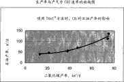
图3为根据实施例7绘制的石油生产速率对产气中CO2速率的曲线图。3 is a graph of oil production rate versusCO2 rate in gas produced according to Example 7.
具体实施方式Detailed ways
THAITM方法的操作已在美国专利5626191和6412557描述,现简述如下。将氧化气体(通常是空气、氧气或者富氧空气)注入油层的上部。预先铺设的焦炭消耗了其中的氧气,这样只有无氧气体接触焦炭区域前的石油。焦炭燃料氧化产生高温,燃烧气体的温度一般达到600℃,甚至高达1000℃。在流动性石油带(mobile oil zone,MOZ)中,这些高温气体和蒸汽加热石油使其超过400℃,造成部分石油的裂解和某些组分汽化,大大地减低了石油粘度。如沥青等最重的石油组分被留在岩石上。之后,当燃烧前缘到达此区域时,这些残留的组分将构成焦炭燃料。在流动性石油带(MOZ)中,由于重力和钻井低压沉降的作用下,气体和石油向下流入水平井。焦炭带和流动性石油带(MOZ)沿着侧面由直井的端部移向跟部。燃烧前缘后面的区域为已燃烧区。在流动性石油带(MOZ)之前的是冷油。The operation of the THAI™ method has been described in US Patent Nos. 5,626,191 and 6,412,557 and is briefly described below. An oxidizing gas (usually air, oxygen or oxygen-enriched air) is injected into the upper part of the reservoir. The pre-laid coke consumes the oxygen in it so that only oxygen-free gas contacts the oil before the coke area. Oxidation of coke fuel produces high temperature, and the temperature of combustion gas generally reaches 600°C, even as high as 1000°C. In the mobile oil zone (MOZ), these high-temperature gases and steam heat the oil to over 400°C, causing partial cracking of the oil and vaporization of certain components, greatly reducing the viscosity of the oil. The heaviest petroleum components, such as bitumen, are left on the rock. Later, when the combustion front reaches this area, these remaining components will constitute coke fuel. In the Mobility Oil Zone (MOZ), gas and oil flow down horizontal wells due to gravity and low-pressure subsidence of the well. The coke zone and mobile oil zone (MOZ) move from the end of the vertical well to the heel along the side. The area behind the combustion front is the burned zone. Before the mobile oil zone (MOZ) is cold oil.
由于燃烧前缘的推进,油层的已燃烧区中流体(油和水)被排空并充满了氧化气体,令位于已燃烧区对面的直井区域具有接收氧气的危险,这将燃烧井中的石油,产生极高的井筒温度,可能损坏管套尤其是砂筛。砂筛能允许流体进入井筒却阻挡砂子的进入。如果砂筛失效,松散的油层砂子将进入井筒。为了清洁和修补水泥塞就必须封堵井,但由于井筒中石油和氧气的浓度可能达到爆炸程度,此项操作困难而又危险。Due to the advancement of the combustion front, the fluid (oil and water) in the burned zone of the reservoir is emptied and filled with oxidizing gases, so that the vertical well area located opposite the burned zone is at risk of receiving oxygen, which will burn the oil in the well, Extremely high wellbore temperatures are generated, which may damage the casing, especially the sand screen. Sand screens allow fluids to enter the wellbore but block sand. If the sand screen fails, loose reservoir sand will enter the wellbore. The well must be plugged in order to clean and repair the cement plug, a difficult and dangerous operation due to potentially explosive concentrations of oil and oxygen in the wellbore.
为了量化流体注入水平井筒的效果,可以进行若干计算机数值模拟处理。蒸汽以下面两种方式按不同速率注入水平井中:1、通过置于水平井中的管道;2、通过一个从位于水平井端部附近的油层基周围延伸的分层井。这两种方法均减少了氧气进入井筒的趋势,并且带来惊奇且意外的效果:石油采收率变大而井筒中的碳堆积却减少了。因此,可以使用更高的氧化气体注入速率,并同时保持操作安全。In order to quantify the effect of fluid injection into a horizontal wellbore, several computer numerical simulations can be performed. Steam is injected into the horizontal well at different rates in two ways: 1. through tubing placed in the horizontal well; 2. through a layered well extending from around the reservoir base near the end of the horizontal well. Both of these methods reduce the tendency of oxygen to enter the wellbore and have the surprising and unexpected effect of greater oil recovery and less carbon buildup in the wellbore. Therefore, higher oxidizing gas injection rates can be used while maintaining operational safety.
关于THAITM方法的安全性,业已发现向油层加入蒸汽的以上两种方法均具有减少氧化气体进入水平井筒的优点。这样可以采用更高氧化气体注入速率,同时得到更高石油采收率。Regarding the safety of the THAITM method, it has been found that the above two methods of adding steam to the reservoir have the advantage of reducing the entry of oxidizing gas into the horizontal wellbore. This allows higher oxidizing gas injection rates to be employed while resulting in higher oil recovery.
用THAITM方法进行大量的计算机模拟,可以评估注入蒸汽或非氧化气体使水平井筒压力减少的效果。软件STARSTM火烧油层模拟器(STARSTM In SituCombustion Simulator)由加拿大艾博塔省卡尔加里塔计算机模拟集团(Computer Modelling Group,Calgary,Alberta,Canada.)公司提供。Extensive computer simulations using the THAITM method can evaluate the effect of injecting steam or non-oxidizing gas on reducing the pressure in the horizontal wellbore. The software STARSTM In Situ Combustion Simulator (STARSTM In Situ Combustion Simulator) is provided by Computer Modeling Group, Calgary, Alberta, Canada.
表4.模型参数表Table 4. Model parameter table
模拟器:STARS TM 2003.13,Simulator: STARSTM 2003.13,
计算机模拟集团公司(Computer Modelling Group Limited)Computer Modeling Group Limited
模型尺寸:Model size:
每个长250m,100个井格块Each length is 250m, 100 well blocks
宽25m,20个井格块25m wide, 20 well grid blocks
高20m,20个井格块20m high, 20 well grid blocks
单个井格块尺寸:2.5m x 2.5m x 1.0m(长宽高).Single well block size: 2.5m x 2.5m x 1.0m (length, width and height).
水平生产井:Horizontal production well:
一个水平部分为135m的分离井从井格块26,1,3延伸至80,1,3A split well with a horizontal section of 135m extends from blocks 26, 1, 3 to 80, 1, 3
该端部自直空气注入器偏移15mThe end is offset 15m from the straight air injector
直注入井:Direct injection well:
氧化气体(空气)注入点:20,1,1∶4(从上向下数第4个井格块)Oxidation gas (air) injection points: 20, 1, 1:4 (the 4th grid block from top to bottom)
氧化气体注入速率:65,000m3/天,或85,000m3/天或100,000m3/天Oxidation gas injection rate: 65,000m3 /day, or 85,000m3 /day or 100,000m3 /day
蒸汽注入点:20,1,19∶20(从下向上数第2个井格块)Steam injection point: 20, 1, 19:20 (the second well block from bottom to top)
岩石/流体参数Rock/Fluid Parameters
组分:水、沥青、升级石油,甲烷、CO2、CO/N2、氧气、焦炭Components: Water, Bitumen, Upgraded Petroleum, Methane, CO2 , CO/N2, Oxygen, Coke
杂质:均质砂子Impurities: homogeneous sand
渗透性:6.7D(h),3.4D(v)Permeability: 6.7D(h), 3.4D(v)
孔隙度:33%Porosity: 33%
饱和度:沥青80%、水20%、气体摩尔分数0.114Saturation:
沥青粘性:10℃.340000cPAsphalt viscosity: 10℃.340000cP
沥青平均分子量:550AMUAverage molecular weight of asphalt: 550AMU
升级石油粘性:10℃.664cPUpgrade oil viscosity: 10℃.664cP
升级石油平均分子量:330AMUUpgraded oil average molecular weight: 330AMU
物理状态:Physical state:
油层温度:20℃.Reservoir temperature: 20°C.
原生油藏压力:2600kPa.Primary reservoir pressure: 2600kPa.
井底压力:4000kPa.Bottom hole pressure: 4000kPa.
反应式:Reaction formula:
1.1.0沥青---->0.42升级石油+1.3375 CH4+20焦炭1.1.0 Asphalt ----> 0.42 Upgrade Oil +1.3375 CH4 +20 Coke
2.1.0沥青+16 O2^0.05----->12.5水+5.0 CH4+9.5 CO2+0.5 CO/N2+15焦炭2.1.0 asphalt+16 O2 ^0.05----->12.5 water+5.0 CH4 +9.5 CO2 +0.5 CO/N2 +15 coke
3.1.0焦炭+1.225 O2----->0.5水+0.95 CO2+0.05 CO/N23.1.0 coke+1.225 O2 ----->0.5 water+0.95 CO2 +0.05 CO/N2
实施例:Example:
实施例1:Example 1:
表1a表示以65000M3/天的空气注入速率(标准温度和压力)将空气注入直注入器(图1中E点所示)的模拟结果。本发明不涉及在井J中I点的油层基注入蒸汽为零的情景。当空气速率为65000M3/天时,没有氧气进入水平井筒,在零蒸汽注入量时也是如此,此时最高井筒温度不超过425℃。Table 1a presents the simulation results of injecting air into the straight injector (shown at point E in Figure 1) at an air injection rate of 65000M3 /day (standard temperature and pressure). The present invention does not relate to the scenario of zero injected steam at the base of the reservoir at point I in well J. When the air rate is 65000M3 /day, no oxygen enters the horizontal wellbore, and it is the same when the steam injection rate is zero, and the maximum wellbore temperature does not exceed 425°C at this time.
但是出乎意料的是,从以下数据可以看出,蒸汽以5M3/天和10M3/天(水当量)的较少量在油层低点(图1中E点)注入时,提高了石油采收率。若注入介质为蒸汽,以下数据提供的是此蒸汽水当量的体积,否则很难确定所供蒸汽的体积,因为蒸汽与其所处油层的压力有关。当然,当水注入该油层并在进入油层过程中最后变为蒸汽时,产生的蒸汽量只是以下提供的水当量,通常是供水的体积的1000倍数量级左右(由压力决定)。But unexpectedly, it can be seen from the following data that when steam is injected at the low point of the reservoir (point E in Fig. 1) with a small amount of 5M3 /day and 10M3 /day (water equivalent), the recovery factor. If the injection medium is steam, the following data provide the water equivalent volume of this steam, otherwise it is difficult to determine the volume of steam supplied, because the steam is related to the pressure of the oil layer where it is located. Of course, when water is injected into the oil layer and finally turns into steam during the process of entering the oil layer, the amount of steam produced is only the water equivalent provided below, which is usually about 1000 times the volume of the water supply (determined by the pressure).
表1a:空气速率65000m3/天——在油层基注入蒸汽Table 1a: Air Velocity 65000m3 /day - Steam Injection at Reservoir Base
蒸汽注入 井的最 井筒中 井筒中 沥青 平均石油steam injected into the wellbore in the wellbore in the wellbore bitumen average oil
速率 高温度 最大焦炭量 最大氧气量 采收率 生产量Rate High Temperature Maximum Coke Capacity Maximum Oxygen Recovery Rate Production Capacity
m3/天m3 /day
(水当量) ℃. % % %OOIP m3/天(water equivalent) ℃. % % % OOIP m3 /day
*0 410 90 0 35.1 28.3* 0 410 90 0 35.1 28.3
5 407 79 0 38.0 29.05 407 79 0 0 38.0 29.0
10 380 76 0 43.1 29.810 380 76 0 43.1 29.8
*非本发明的部分* Not part of the invention
实施例2Example 2
表1b表示通过临近端部的内管道G向水平井注入蒸汽的结果,油层的上部空气的注入速率为65000M3/天(标准温度和标准压力)。井筒最高温度的降低与注入的蒸汽量成比例。石油采收率相对于零蒸汽时的数值有所增加,沉积于井筒中焦炭的最大体积百分比随着注入蒸汽量的增加而减小。它带来了很好的效果,即在相同压力下,与水平井端部未注入蒸汽的井相比,井筒中的压降会减小,流体更易流动。Table 1b shows the results of injecting steam into the horizontal well through the inner pipe G near the end, and the injection rate of air in the upper part of the oil layer is 65000M3 /day (standard temperature and standard pressure). The reduction in maximum wellbore temperature is proportional to the amount of steam injected. The oil recovery increases relative to the value at zero steam, and the maximum volume percentage of coke deposited in the wellbore decreases with increasing steam injection. It has the nice effect that at the same pressure, the pressure drop in the wellbore is reduced and the fluids are more mobile compared to a well with no steam injected at the tip of a horizontal well.
表1b. 空气速率65000m3/天 向井管注入蒸汽Table 1b. Air velocity 65000m3 /day Injecting steam into the well pipe
蒸汽注入 井的最 井筒中最大 井筒中最大 沥青 平均石油steam injection well max max in wellbore max in wellbore bitumen average oil
速率 高温度 焦炭量 氧气量 采收率 生产量Rate High Temperature Coke Amount Oxygen Amount Recovery Efficiency Production
m3/天m3 /day
(水当量) ℃. % % %OOIP m3/天(water equivalent) ℃. % % % OOIP m3 /day
*0 410 90 0 35.1 28.6* 0 410 90 0 35.1 28.6
5 366 80 0 43.4 30.05 366 80 0 43.4 30.0
10 360 45 0 43.4 29.810 360 45 0 43.4 29.8
*非本发明的部分* Not part of the invention
实施例3Example 3
在本实施例中,空气注入速率增加到85000m3/天(标准温度和标准压力),导致如表2a所示的氧气突破。在零蒸汽注入的例子中,井筒中的氧浓度为8.8%。井筒的最高温度达到1074℃。97%的沉积焦炭降低了井筒渗透率。在采油的同时,通过直注入井C(见图1)在油层基注入12m3/天(水当量)的蒸汽,大大优化了零氧气突破、焦炭量和采收率指标。In this example, the air injection rate was increased to 85000m3 /day (standard temperature and pressure), resulting in oxygen breakthrough as shown in Table 2a. In the case of zero steam injection, the oxygen concentration in the wellbore was 8.8%. The maximum temperature of the wellbore reached 1074°C. 97% deposited coke reduces wellbore permeability. Simultaneously with oil production, 12m3 /day (water equivalent) of steam is injected into the base of the oil layer through the direct injection well C (see Fig. 1), which greatly optimizes the indicators of zero oxygen breakthrough, coke volume and recovery factor.
表2a:空气速率85000m3/天 向油层基注入蒸汽Table 2a: Air Velocity 85000m3 /day Steam Injection into Reservoir Base
蒸汽注入 井的最 井筒中最大 井筒中最大 沥青 平均石油steam injection well max max in wellbore max in wellbore bitumen average oil
速率 高温度 焦炭量 氧气量 采收率 生产量Rate High Temperature Coke Volume Oxygen Recovery Rate Production
m3/天m3 /day
(水当量) ℃. % % %OOIP m3/天(water equivalent) ℃. % % % OOIP m3 /day
*0 1074 97 8.8* 0 1074 97 8.8
5 518 80 05 518 80 0
12 414 43 0 36.1 33.412 414 43 0 36.1 33.4
*非本发明的部分* Not part of the invention
实施例4Example 4
表2b显示当空气速率为85000m3/天时,通过内管道G(见图1)注入蒸汽的燃烧性能。为了防止氧气突破和超过井筒耐受的最高温度,还需要注入10m3/天(水当量)的蒸汽。Table 2b shows the combustion performance of steam injected through the inner duct G (see Fig. 1) when the air rate is 85000 m3 /day. In order to prevent oxygen breakthrough and exceed the maximum temperature the wellbore can withstand, it is also necessary to inject 10m3 /day (water equivalent) of steam.
表2b:空气速率85000m3/天向井筒注入蒸汽Table 2b: Injection of steam into the wellbore at an air rate of 85000m3 /day
蒸汽注入 井的最 井筒中最大 井筒中最大 沥青 平均石油Steam Injection Well Maximum in Wellbore Maximum in Wellbore Bitumen Average Oil
速率 高温度 焦炭量 氧气量 采收率 生产量Rate High Temperature Coke Amount Oxygen Amount Recovery Efficiency Production
m3/天m3 /day
(水当量) ℃. % % %OOIP m3/天(water equivalent) ℃. % % % OOIP m3 /day
*0 1074 100 8.8* 0 1074 100 8.8
5 500 96 1.85 500 96 1.8
10 407 45 0 37.3 33.210 407 45 0 37.3 33.2
*非本发明的部分* Not part of the invention
实施例5Example 5
为了进一步测试在各高空气注入速率下的不同效果,在气体注入量为100000m3/天的情况下进行几个试验。表3a中的结果表明,必须在油层基处(即图1中直井C中的B-E)同时以20m3/天(水当量)的速率注入蒸汽,以阻止氧气突破进入水平井管中;而在空气注入速率为85000m3/天时,达到同样的效果,蒸汽注入速率仅需要10m3/天(水当量)。In order to further test the different effects at various high air injection rates, several experiments were performed with a gas injection rate of 100,000 m3 /day. The results in Table 3a show that it is necessary to simultaneously inject steam at the rate of 20 m3 /day (water equivalent) at the base of the reservoir (i.e. BE in vertical well C in Fig. 1) to prevent oxygen from breaking through into the horizontal well tubing; When the air injection rate is 85000m3 /day, to achieve the same effect, the steam injection rate only needs 10m3 /day (water equivalent).
表3a:空气速率100000m3/天 向油层基注入蒸汽Table 3a: Air Velocity 100000m3 /day Steam Injection into Reservoir Base
蒸汽注入 井的最 井筒中 井筒中 沥青 平均石油steam injected into the well's maximum wellbore in the wellbore bitumen average oil
速率 高温度 最大焦炭量 最大氧气量 采收率 生产量Rate High Temperature Maximum Coke Capacity Maximum Oxygen Recovery Rate Production Capacity
m3/天m3 /day
(水当量) ℃. % % %OOIP m3/天(water equivalent) ℃. % % % OOIP m3 /day
*0 1398 100 10.4* 0 1398 100 10.4
5 1151 100 7.25 1151 100 7.2
10 1071 100 6.010 1071 100 6.0
20 425 78 0 34.5 35.620 425 78 0 34.5 35.6
*非本发明的部分* Not part of the invention
实施例6Example 6
表3b显示在向油层以100000m3/天注入空气的同时向井管G(见图1)注入蒸汽的结果。为了防止氧气进入水平井管,同时需要向油层基注入蒸汽,需要的蒸汽速率为20m3/天(水当量)。Table 3b shows the results of injecting steam into well G (see Fig. 1 ) while injecting air into the reservoir at 100000 m3 /day. In order to prevent oxygen from entering the horizontal well pipe and inject steam into the reservoir base at the same time, the required steam rate is 20m3 /day (water equivalent).
表3a: 空气速率 100000m3/天 向油层基注入蒸汽Table 3a: Air Velocity 100000m3 /day Steam Injection into Reservoir Base
蒸汽注入 井的最 井筒中最大 井筒中最大 沥青 平均石油steam injection well max max in wellbore max in wellbore bitumen average oil
速率 高温度 焦炭量 氧气量 采收率 生产量Rate High Temperature Coke Amount Oxygen Amount Recovery Efficiency Production
m3/天m3 /day
(水当量) ℃. % % %OOIP m3/天(water equivalent) ℃. % % % OOIP m3 /day
*0 1398 100 10.4* 0 1398 100 10.4
5 1151 100 7.25 1151 100 7.2
10 1071 100 6.010 1071 100 6.0
20 425 78 0 34.5 35.620 425 78 0 34.5 35.6
*非本发明的部分* Not part of the invention
实施例7Example 7
下面表4显示在生产石油的THAITM方法中,向单个直注入井与水平生产井的组合中注入氧气和非氧化气体组合物(即氮气和二氧化碳)的不同情形,比较数据由STARSTM火烧油层模拟器(STARSTM In Situ Combustion Simulator)软件获得,该软件是由加拿大艾博塔省卡尔加里塔计算机模拟集团(ComputerModelling Group)提供。除了模拟油层为100米宽和500米长之外,其它数据与以上六个实施例相同。每次测试蒸汽均以10m3/天的速率通过生产井水平部分的管道注入。Table 4 below shows the different situations of injecting oxygen and non-oxidizing gas composition (i.e. nitrogen and carbon dioxide) into a combination of a single straight injection well and a horizontal production well in the THAITM method of producing oil. Simulator (STARSTM In Situ Combustion Simulator) software was obtained from Calgary Tower, Alberta, Canada (ComputerModelling Group). Except that the simulated oil reservoir is 100 meters wide and 500 meters long, other data are the same as the above six embodiments. Each test steam was injected at a rate of 10m3 /day through the pipeline in the horizontal part of the production well.

对比上述表4中行1和行2中可以看出,假设惰性气体为CO2,当行2中氧气和惰性气体减少50%,石油采收率还是与行1差不多。这意味着行2中气体压缩成本减少一半,而石油生产得更快。Comparing row 1 and row 2 in Table 4 above, it can be seen that assuming the inert gas is CO2 , when the oxygen and inert gas in row 2 are reduced by 50%, the oil recovery rate is still similar to row 1. This means gas compression costs are cut in half in row 2, and oil is produced faster.
从表4可以进一步看出,行1中注入注入井的氧气为17.85摩尔百分数,氮为67.15摩尔百分数,估计石油采收率为41m3/天。与之类似,行4的类似注入注入井的氧气为17.85摩尔百分数,二氧化碳为67.15摩尔百分数,石油生产率则是行1的3.3倍(136m3/天)。It can further be seen from Table 4 that the injection well in row 1 has 17.85 mole percent oxygen, 67.15 mole percent nitrogen, and an estimated oil recovery of 41 m3 /day. Similarly, the similar injection wells of row 4 had 17.85 mole percent oxygen and 67.15 mole percent carbon dioxide, and the oil production rate was 3.3 times that of row 1 (136 m3 /day).
表4进一步显示,如行6所示,注入相等量的氧气和CO2,若总注入体积为85000m3/天,石油采收率则增加至2.7倍。Table 4 further shows that, as shown in row 6, injecting equal amounts of oxygen and CO2 increases the oil recovery by a factor of 2.7 for a total injected volume of 85000 m3 /day.
表4中的行7表示了在空气中加入CO2作为注入气体所带来的效果。与行1相比,石油采收增加至1.7倍但无需增加压缩成本。这样的好处是不需要设置氧气分离设备。Row 7 in Table 4 shows the effect of addingCO2 to air as the injection gas. Compared to row 1, oil recovery was increased by a factor of 1.7 without increasing compression costs. The advantage of this is that no oxygen separation equipment is required.
图3所示为基于实施例7的石油生产速率与产气中CO2速率的曲线图,在火烧油层过程中,石油生产速率与产气中CO2速率之间密切相关。CO2的产率依赖于两个CO2源:注入的CO2和油层中焦炭燃烧产生的CO2。所以CO2会处于进入火烧油层和火烧油层中的两种情况下,它们彼此影响很大,甚至在具有不动油的油层中也是如此(本发明中即是如此)。Fig. 3 is a graph showing the oil production rate and the CO2 rate in gas production based on Example 7. In the process of burning oil reservoirs, the oil production rate is closely related to the CO2 rate in gas production. The yield of CO2 depends on two sources of CO2 : injected CO2 and CO2 from coke combustion in the oil reservoir. So theCO2 will be in two cases going into the inflamed oil reservoir and in the inflamed oil reservoir, and they will greatly affect each other, even in the oil reservoir with non-moving oil (which is the case in this invention).
总结Summarize
当蒸汽注入量固定时,平均每天石油采收率随空气注入速率而增加。因于清扫流体的体积是增加的,所以这样的结果出人意料。令人惊讶的是,总的石油采收量却随着注入空气速率的增加而减少。此现象发生在空气注入阶段内(即燃烧前缘到达水平井跟部的时间)。另外,将二氧化碳注入直井和/或水平生产井可以提高生产速率。When the steam injection rate is fixed, the average daily oil recovery rate increases with the air injection rate. This result is unexpected because the volume of sweeping fluid is increased. Surprisingly, total oil recovery decreased with increasing air injection rate. This phenomenon occurs during the air injection phase (ie, the time when the combustion front reaches the heel of the horizontal well). Additionally, injecting carbon dioxide into vertical and/or horizontal production wells can increase production rates.
虽然前面公开了本发明的内容,并描述了优选的实施例,但应当了解,本发明不仅限于这些特定实施例。对本领域的技术人员而言,本发明还可以有许多变化和修改。所述的权利要求对本发明进行了限定。While the foregoing discloses the invention and describes preferred embodiments, it should be understood that the invention is not limited to these specific embodiments. For those skilled in the art, the present invention can also have many variations and modifications. The following claims define the invention.
Claims (20)
Translated fromChineseApplications Claiming Priority (3)
| Application Number | Priority Date | Filing Date | Title |
|---|---|---|---|
| US77775206P | 2006-02-27 | 2006-02-27 | |
| US60/777,752 | 2006-02-27 | ||
| PCT/CA2007/000312WO2007095764A1 (en) | 2006-02-27 | 2007-02-27 | Diluent-enhanced in-situ combustion hydrocarbon recovery process |
Publications (2)
| Publication Number | Publication Date |
|---|---|
| CN101427006Atrue CN101427006A (en) | 2009-05-06 |
| CN101427006B CN101427006B (en) | 2014-07-16 |
Family
ID=38436907
Family Applications (1)
| Application Number | Title | Priority Date | Filing Date |
|---|---|---|---|
| CN200780014674.5AExpired - Fee RelatedCN101427006B (en) | 2006-02-27 | 2007-02-27 | Method for extracting liquid hydrocarbons from underground oil formations |
Country Status (12)
| Country | Link |
|---|---|
| US (2) | US7984759B2 (en) |
| CN (1) | CN101427006B (en) |
| CA (1) | CA2643739C (en) |
| CO (1) | CO6440560A2 (en) |
| EC (1) | ECSP088780A (en) |
| EG (1) | EG25806A (en) |
| GB (3) | GB2478237B (en) |
| MX (1) | MX2008010951A (en) |
| NO (1) | NO20084084L (en) |
| RU (1) | RU2406819C2 (en) |
| TR (1) | TR200809049T1 (en) |
| WO (1) | WO2007095764A1 (en) |
Cited By (1)
| Publication number | Priority date | Publication date | Assignee | Title |
|---|---|---|---|---|
| CN102933792A (en)* | 2010-03-30 | 2013-02-13 | 亚康科技股份有限公司 | Improved in situ combustion recovery method using a single horizontal well to produce oil and combustion gas to the surface |
Families Citing this family (12)
| Publication number | Priority date | Publication date | Assignee | Title |
|---|---|---|---|---|
| US8167036B2 (en)* | 2006-01-03 | 2012-05-01 | Precision Combustion, Inc. | Method for in-situ combustion of in-place oils |
| US7984759B2 (en)* | 2006-02-27 | 2011-07-26 | Archon Technologies Ltd. | Diluent-enhanced in-situ combustion hydrocarbon recovery process |
| US7740062B2 (en) | 2008-01-30 | 2010-06-22 | Alberta Research Council Inc. | System and method for the recovery of hydrocarbons by in-situ combustion |
| US7841404B2 (en)* | 2008-02-13 | 2010-11-30 | Archon Technologies Ltd. | Modified process for hydrocarbon recovery using in situ combustion |
| US8210259B2 (en) | 2008-04-29 | 2012-07-03 | American Air Liquide, Inc. | Zero emission liquid fuel production by oxygen injection |
| CA2693640C (en) | 2010-02-17 | 2013-10-01 | Exxonmobil Upstream Research Company | Solvent separation in a solvent-dominated recovery process |
| CA2696638C (en) | 2010-03-16 | 2012-08-07 | Exxonmobil Upstream Research Company | Use of a solvent-external emulsion for in situ oil recovery |
| CA2705643C (en) | 2010-05-26 | 2016-11-01 | Imperial Oil Resources Limited | Optimization of solvent-dominated recovery |
| CA2771703A1 (en)* | 2012-03-16 | 2013-09-16 | Sunshine Oilsands Ltd. | Fully controlled combustion assisted gravity drainage process |
| CA2780670C (en) | 2012-06-22 | 2017-10-31 | Imperial Oil Resources Limited | Improving recovery from a subsurface hydrocarbon reservoir |
| RU2515662C1 (en)* | 2013-05-20 | 2014-05-20 | Открытое акционерное общество "Татнефть" им. В.Д. Шашина | Oil deposit development method |
| RU2570865C1 (en)* | 2014-08-21 | 2015-12-10 | Евгений Николаевич Александров | System for improvement of airlift efficiency at pumping formation fluid from subsurface resources |
Family Cites Families (28)
| Publication number | Priority date | Publication date | Assignee | Title |
|---|---|---|---|---|
| US3502372A (en)* | 1968-10-23 | 1970-03-24 | Shell Oil Co | Process of recovering oil and dawsonite from oil shale |
| US3565174A (en)* | 1969-10-27 | 1971-02-23 | Phillips Petroleum Co | Method of in situ combustion with intermittent injection of volatile liquid |
| US4005752A (en)* | 1974-07-26 | 1977-02-01 | Occidental Petroleum Corporation | Method of igniting in situ oil shale retort with fuel rich flue gas |
| GB1480675A (en)* | 1974-12-02 | 1977-07-20 | Texaco Development Corp | Vertical conditionally miscible oil recovery process |
| US4069868A (en)* | 1975-07-14 | 1978-01-24 | In Situ Technology, Inc. | Methods of fluidized production of coal in situ |
| US4429744A (en)* | 1981-05-08 | 1984-02-07 | Mobil Oil Corporation | Oil recovery method |
| US4425967A (en)* | 1981-10-07 | 1984-01-17 | Standard Oil Company (Indiana) | Ignition procedure and process for in situ retorting of oil shale |
| US4410042A (en)* | 1981-11-02 | 1983-10-18 | Mobil Oil Corporation | In-situ combustion method for recovery of heavy oil utilizing oxygen and carbon dioxide as initial oxidant |
| US4436153A (en)* | 1981-12-31 | 1984-03-13 | Standard Oil Company | In-situ combustion method for controlled thermal linking of wells |
| US4415031A (en)* | 1982-03-12 | 1983-11-15 | Mobil Oil Corporation | Use of recycled combustion gas during termination of an in-situ combustion oil recovery method |
| US4886118A (en)* | 1983-03-21 | 1989-12-12 | Shell Oil Company | Conductively heating a subterranean oil shale to create permeability and subsequently produce oil |
| US4570715A (en)* | 1984-04-06 | 1986-02-18 | Shell Oil Company | Formation-tailored method and apparatus for uniformly heating long subterranean intervals at high temperature |
| US4566537A (en)* | 1984-09-20 | 1986-01-28 | Atlantic Richfield Co. | Heavy oil recovery |
| US4598770A (en)* | 1984-10-25 | 1986-07-08 | Mobil Oil Corporation | Thermal recovery method for viscous oil |
| US5054551A (en)* | 1990-08-03 | 1991-10-08 | Chevron Research And Technology Company | In-situ heated annulus refining process |
| US5217076A (en)* | 1990-12-04 | 1993-06-08 | Masek John A | Method and apparatus for improved recovery of oil from porous, subsurface deposits (targevcir oricess) |
| CA2058255C (en)* | 1991-12-20 | 1997-02-11 | Roland P. Leaute | Recovery and upgrading of hydrocarbons utilizing in situ combustion and horizontal wells |
| RU2087690C1 (en)* | 1995-01-11 | 1997-08-20 | Татарский Государственный Научно-Исследовательский И Проектный Институт Нефтяной Промышленности | Method for development of high-viscous oil by in-bed burning |
| US5626191A (en)* | 1995-06-23 | 1997-05-06 | Petroleum Recovery Institute | Oilfield in-situ combustion process |
| US5868202A (en)* | 1997-09-22 | 1999-02-09 | Tarim Associates For Scientific Mineral And Oil Exploration Ag | Hydrologic cells for recovery of hydrocarbons or thermal energy from coal, oil-shale, tar-sands and oil-bearing formations |
| WO1999030002A1 (en)* | 1997-12-11 | 1999-06-17 | Petroleum Recovery Institute | Oilfield in situ hydrocarbon upgrading process |
| US6412556B1 (en)* | 2000-08-03 | 2002-07-02 | Cdx Gas, Inc. | Cavity positioning tool and method |
| CA2462359C (en)* | 2004-03-24 | 2011-05-17 | Imperial Oil Resources Limited | Process for in situ recovery of bitumen and heavy oil |
| AR050826A1 (en)* | 2004-06-07 | 2006-11-29 | Archon Technologies Ltd | IN SITU COMBUSTION PROCESS IMPROVED IN OIL SITUATION |
| US7493952B2 (en) | 2004-06-07 | 2009-02-24 | Archon Technologies Ltd. | Oilfield enhanced in situ combustion process |
| CA2492306A1 (en)* | 2005-01-13 | 2006-07-13 | Encana | In situ combustion following primary recovery processes utilizing horizontal well pairs in oil sands and heavy oil reservoirs |
| US7581587B2 (en)* | 2006-01-03 | 2009-09-01 | Precision Combustion, Inc. | Method for in-situ combustion of in-place oils |
| US7984759B2 (en)* | 2006-02-27 | 2011-07-26 | Archon Technologies Ltd. | Diluent-enhanced in-situ combustion hydrocarbon recovery process |
- 2007
- 2007-02-27USUS12/280,832patent/US7984759B2/ennot_activeExpired - Fee Related
- 2007-02-27CNCN200780014674.5Apatent/CN101427006B/ennot_activeExpired - Fee Related
- 2007-02-27RURU2008138383/03Apatent/RU2406819C2/ennot_activeIP Right Cessation
- 2007-02-27CACA2643739Apatent/CA2643739C/ennot_activeExpired - Fee Related
- 2007-02-27TRTR2008/09049Tpatent/TR200809049T1/enunknown
- 2007-02-27MXMX2008010951Apatent/MX2008010951A/enactiveIP Right Grant
- 2007-02-27GBGB1109740Apatent/GB2478237B/ennot_activeExpired - Fee Related
- 2007-02-27GBGB0817709Apatent/GB2450820B/ennot_activeExpired - Fee Related
- 2007-02-27GBGB1109736Apatent/GB2478236B/ennot_activeExpired - Fee Related
- 2007-02-27WOPCT/CA2007/000312patent/WO2007095764A1/enactiveApplication Filing
- 2008
- 2008-08-27EGEG2008081448Apatent/EG25806A/enactive
- 2008-09-25NONO20084084Apatent/NO20084084L/ennot_activeApplication Discontinuation
- 2008-09-26COCO08102772Apatent/CO6440560A2/ennot_activeApplication Discontinuation
- 2008-09-29ECEC2008008780Apatent/ECSP088780A/enunknown
- 2011
- 2011-06-28USUS13/171,086patent/US8118096B2/ennot_activeExpired - Fee Related
Cited By (1)
| Publication number | Priority date | Publication date | Assignee | Title |
|---|---|---|---|---|
| CN102933792A (en)* | 2010-03-30 | 2013-02-13 | 亚康科技股份有限公司 | Improved in situ combustion recovery method using a single horizontal well to produce oil and combustion gas to the surface |
Also Published As
| Publication number | Publication date |
|---|---|
| CA2643739C (en) | 2011-10-04 |
| TR200809049T1 (en) | 2009-03-23 |
| ECSP088780A (en) | 2008-11-27 |
| CO6440560A2 (en) | 2012-05-15 |
| GB2450820A (en) | 2009-01-07 |
| NO20084084L (en) | 2008-11-27 |
| EG25806A (en) | 2012-08-14 |
| GB2478236A (en) | 2011-08-31 |
| GB2478236B (en) | 2011-11-02 |
| RU2406819C2 (en) | 2010-12-20 |
| RU2008138383A (en) | 2010-04-10 |
| GB2478237A (en) | 2011-08-31 |
| US20090308606A1 (en) | 2009-12-17 |
| GB2478237B (en) | 2011-11-02 |
| US7984759B2 (en) | 2011-07-26 |
| MX2008010951A (en) | 2009-01-23 |
| US8118096B2 (en) | 2012-02-21 |
| GB0817709D0 (en) | 2008-11-05 |
| WO2007095764A1 (en) | 2007-08-30 |
| GB201109736D0 (en) | 2011-07-27 |
| CN101427006B (en) | 2014-07-16 |
| US20110253371A1 (en) | 2011-10-20 |
| CA2643739A1 (en) | 2007-08-30 |
| GB201109740D0 (en) | 2011-07-27 |
| GB2450820B (en) | 2011-08-17 |
Similar Documents
| Publication | Publication Date | Title |
|---|---|---|
| CN101427006B (en) | Method for extracting liquid hydrocarbons from underground oil formations | |
| CN1993534B (en) | Improved In-Situ Combustion Technology in Oilfield | |
| CA2579854C (en) | Oilfield enhanced in situ combustion process | |
| CA2650130C (en) | System and method for the recovery of hydrocarbons by in-situ combustion | |
| US20130106117A1 (en) | Low Emission Heating of A Hydrocarbon Formation | |
| US20130098607A1 (en) | Steam Flooding with Oxygen Injection, and Cyclic Steam Stimulation with Oxygen Injection | |
| CN102037211A (en) | Field management for substantially constant composition gas generation | |
| Moore et al. | Potential for in situ combustion in depleted conventional oil reservoirs | |
| CN116411905B (en) | A method for exploiting water-invaded condensate gas reservoir | |
| Fassihi et al. | Safety considerations for air injection into light oil reservoirs | |
| HK1132779A (en) | Diluent-enhanced in-situ combustion hydrocarbon recovery process | |
| Fraim et al. | Pleito Creek: A Commercial Demonstration of a High-Pressure, In-Situ Combustion Process Using Enriched Air for Near Miscible Displacement of Heavy Oil to Horizontal Production Wells | |
| HK1132778A (en) | Oilfield enhanced in situ combustion process | |
| HK1109438B (en) | Oilfield enhanced in situ combustion process | |
| HK1158287A (en) | Oilfield enhanced in situ combustion process |
Legal Events
| Date | Code | Title | Description |
|---|---|---|---|
| C06 | Publication | ||
| PB01 | Publication | ||
| C10 | Entry into substantive examination | ||
| SE01 | Entry into force of request for substantive examination | ||
| REG | Reference to a national code | Ref country code:HK Ref legal event code:DE Ref document number:1132779 Country of ref document:HK | |
| C14 | Grant of patent or utility model | ||
| GR01 | Patent grant | ||
| CF01 | Termination of patent right due to non-payment of annual fee | Granted publication date:20140716 Termination date:20150227 | |
| EXPY | Termination of patent right or utility model | ||
| REG | Reference to a national code | Ref country code:HK Ref legal event code:WD Ref document number:1132779 Country of ref document:HK |